EP4450607A2 - Spitzenvorrichtung, spitzenbehältersatz, spitzenelektrodenvorrichtung und spitzenelektrodensatz - Google Patents
Spitzenvorrichtung, spitzenbehältersatz, spitzenelektrodenvorrichtung und spitzenelektrodensatz Download PDFInfo
- Publication number
- EP4450607A2 EP4450607A2 EP24197295.9A EP24197295A EP4450607A2 EP 4450607 A2 EP4450607 A2 EP 4450607A2 EP 24197295 A EP24197295 A EP 24197295A EP 4450607 A2 EP4450607 A2 EP 4450607A2
- Authority
- EP
- European Patent Office
- Prior art keywords
- tip
- electrode
- connector
- rear end
- base
- Prior art date
- Legal status (The legal status is an assumption and is not a legal conclusion. Google has not performed a legal analysis and makes no representation as to the accuracy of the status listed.)
- Pending
Links
Images





Classifications
-
- C—CHEMISTRY; METALLURGY
- C12—BIOCHEMISTRY; BEER; SPIRITS; WINE; VINEGAR; MICROBIOLOGY; ENZYMOLOGY; MUTATION OR GENETIC ENGINEERING
- C12M—APPARATUS FOR ENZYMOLOGY OR MICROBIOLOGY; APPARATUS FOR CULTURING MICROORGANISMS FOR PRODUCING BIOMASS, FOR GROWING CELLS OR FOR OBTAINING FERMENTATION OR METABOLIC PRODUCTS, i.e. BIOREACTORS OR FERMENTERS
- C12M33/00—Means for introduction, transport, positioning, extraction, harvesting, peeling or sampling of biological material in or from the apparatus
- C12M33/04—Means for introduction, transport, positioning, extraction, harvesting, peeling or sampling of biological material in or from the apparatus by injection or suction, e.g. using pipettes, syringes, needles
-
- B—PERFORMING OPERATIONS; TRANSPORTING
- B01—PHYSICAL OR CHEMICAL PROCESSES OR APPARATUS IN GENERAL
- B01L—CHEMICAL OR PHYSICAL LABORATORY APPARATUS FOR GENERAL USE
- B01L3/00—Containers or dishes for laboratory use, e.g. laboratory glassware; Droppers
- B01L3/02—Burettes; Pipettes
- B01L3/0241—Drop counters; Drop formers
- B01L3/0244—Drop counters; Drop formers using pins
- B01L3/0255—Drop counters; Drop formers using pins characterised by the form or material of the pin tip
-
- B—PERFORMING OPERATIONS; TRANSPORTING
- B01—PHYSICAL OR CHEMICAL PROCESSES OR APPARATUS IN GENERAL
- B01L—CHEMICAL OR PHYSICAL LABORATORY APPARATUS FOR GENERAL USE
- B01L3/00—Containers or dishes for laboratory use, e.g. laboratory glassware; Droppers
- B01L3/50—Containers for the purpose of retaining a material to be analysed, e.g. test tubes
- B01L3/508—Rigid containers without fluid transport within
- B01L3/5082—Test tubes per se
- B01L3/50825—Closing or opening means, corks, bungs
-
- B—PERFORMING OPERATIONS; TRANSPORTING
- B01—PHYSICAL OR CHEMICAL PROCESSES OR APPARATUS IN GENERAL
- B01L—CHEMICAL OR PHYSICAL LABORATORY APPARATUS FOR GENERAL USE
- B01L3/00—Containers or dishes for laboratory use, e.g. laboratory glassware; Droppers
- B01L3/56—Labware specially adapted for transferring fluids
- B01L3/563—Joints or fittings; Separable fluid transfer means to transfer fluids between at least two containers, e.g. connectors
- B01L3/5635—Joints or fittings; Separable fluid transfer means to transfer fluids between at least two containers, e.g. connectors connecting two containers face to face, e.g. comprising a filter
-
- B—PERFORMING OPERATIONS; TRANSPORTING
- B01—PHYSICAL OR CHEMICAL PROCESSES OR APPARATUS IN GENERAL
- B01L—CHEMICAL OR PHYSICAL LABORATORY APPARATUS FOR GENERAL USE
- B01L9/00—Supporting devices; Holding devices
- B01L9/06—Test-tube stands; Test-tube holders
- B01L9/065—Test-tube stands; Test-tube holders specially adapted for capillary tubes
-
- B—PERFORMING OPERATIONS; TRANSPORTING
- B01—PHYSICAL OR CHEMICAL PROCESSES OR APPARATUS IN GENERAL
- B01L—CHEMICAL OR PHYSICAL LABORATORY APPARATUS FOR GENERAL USE
- B01L2300/00—Additional constructional details
- B01L2300/04—Closures and closing means
- B01L2300/046—Function or devices integrated in the closure
-
- B—PERFORMING OPERATIONS; TRANSPORTING
- B01—PHYSICAL OR CHEMICAL PROCESSES OR APPARATUS IN GENERAL
- B01L—CHEMICAL OR PHYSICAL LABORATORY APPARATUS FOR GENERAL USE
- B01L2300/00—Additional constructional details
- B01L2300/06—Auxiliary integrated devices, integrated components
- B01L2300/0609—Holders integrated in container to position an object
-
- B—PERFORMING OPERATIONS; TRANSPORTING
- B01—PHYSICAL OR CHEMICAL PROCESSES OR APPARATUS IN GENERAL
- B01L—CHEMICAL OR PHYSICAL LABORATORY APPARATUS FOR GENERAL USE
- B01L3/00—Containers or dishes for laboratory use, e.g. laboratory glassware; Droppers
- B01L3/02—Burettes; Pipettes
- B01L3/0275—Interchangeable or disposable dispensing tips
-
- B—PERFORMING OPERATIONS; TRANSPORTING
- B01—PHYSICAL OR CHEMICAL PROCESSES OR APPARATUS IN GENERAL
- B01L—CHEMICAL OR PHYSICAL LABORATORY APPARATUS FOR GENERAL USE
- B01L3/00—Containers or dishes for laboratory use, e.g. laboratory glassware; Droppers
- B01L3/50—Containers for the purpose of retaining a material to be analysed, e.g. test tubes
- B01L3/502—Containers for the purpose of retaining a material to be analysed, e.g. test tubes with fluid transport, e.g. in multi-compartment structures
- B01L3/5021—Test tubes specially adapted for centrifugation purposes
Definitions
- the present disclosure relates to a tip device, a tip container set, a tip electrode apparatus, and a tip electrode set.
- Tubular tips such as those described in patent literature (PTL) 1 to 4, are known.
- Such tips may be used as follows for purposes such as measurement, injection, or collection of cells or other such samples.
- liquid is introduced from the rear end of the tip.
- the tip is held in a container that houses the tip.
- the container is then centrifuged so that the head of the tip is filled with liquid without a gap, i.e., without air bubbles.
- the tip is then removed from the container, and a microscope is used to confirm that the head of the tip is filled with liquid without a gap. If the head is not filled with liquid without a gap, the tip is centrifuged again.
- a wire electrode is introduced from the rear end of the tip, and the rear end of the tip is held in an electrode holder. This enables the tip of the electrode to be immersed in the liquid inside the head of the tip.
- the head of the tip is then immersed in the sample, and an electric field is applied between the sample and the electrode to achieve the various purposes described above.
- the present disclosure aims to provide a tip device that enables a tip to be easily inserted into and removed from a container, a tip device that enables a tip to be easily inserted into and removed from an electrode holder, a tip container set that enables a tip to be easily inserted into and removed from a container, a tip electrode apparatus that enables a tip to be easily inserted into and removed from an electrode holder, and a tip electrode set that enables a tip to be easily inserted into and removed from an electrode holder.
- a tip device includes a tubular tip; and a base that is continuous with a rear end of the tip and includes a first connector, wherein the first connector detachably connects to a second connector provided in a container to house the tip. According to this configuration, the tip can easily be inserted into and removed from the container via the base.
- a tip device includes a tubular tip; and a base that is continuous with a rear end of the tip and includes a first connector, wherein the first connector detachably connects to a second connector provided in an electrode holder, and a linear electrode to be introduced into the rear end of the tip protrudes from the electrode holder. According to this configuration, the tip can easily be inserted into and removed from the electrode holder via the base.
- the base may be located between the first connector and a head of the tip and include a grip that is wider in a radial direction of the tip. According to this configuration, the tip can easily be inserted into and removed from the container or the electrode holder by use of the grip.
- the base may include an access hole that communicates with the rear end of the tip. According to this configuration, a liquid or an electrode can easily be introduced into the rear end of the tip via the access hole.
- the access hole may include a guide face that gradually narrows in diameter towards the rear end of the tip. According to this configuration, a liquid or an electrode can more easily be introduced into the rear end of the tip by the guide face.
- the base may include a grounding portion configured to maintain a head of the tip separated from a flat surface on which the tip is placed. According to this configuration, contamination of the head of the tip can be easily controlled when the tip is placed down.
- the grounding portion may be located on an outer peripheral surface of the base. According to this configuration, contamination of the head of the tip can be easily controlled when the head of the tip is observed under a microscope.
- the connectors may connect by concavo-convex engagement with each other. According to this configuration, the tip can be held more reliably by the container or the electrode holder.
- the connectors may connect by screwing together. According to this configuration, the tip can be held even more reliably by the container or the electrode holder.
- the head may be formed as a nano-tip having a nanometer-order inner diameter. According to this configuration, measurement, injection, collection, or the like can easily be performed on a minute portion of a sample, such as an intracellular organ, using the tip device.
- a tip container set includes a tubular tip; a base that is continuous with a rear end of the tip and includes a first connector; and a container configured to house the tip and including a second connector that detachably connects to the first connector. According to this configuration, the tip can easily be inserted into and removed from the container via the base.
- the container may include a communication hole through which an exterior of the container communicates with the rear end of the tip.
- liquid can be introduced through the communication hole from the rear end of the tip while the tip is housed in the container, and the tip can be centrifuged as is, thereby streamlining the work of filling the head of the tip with liquid.
- the container may include a cap and a container body, the cap including the second connector, and the container body including an opening that detachably connects to the cap.
- the container can be configured by a simple structure.
- the base may be located between the first connector and a head of the tip and include a grip that is wider in a radial direction of the tip. According to this configuration, the tip can easily be inserted into and removed from the container by use of the grip.
- the base may include an access hole that communicates with the rear end of the tip. According to this configuration, a liquid or an electrode can easily be introduced into the rear end of the tip via the access hole.
- the access hole may include a guide face that gradually narrows in diameter towards the rear end of the tip. According to this configuration, a liquid or an electrode can more easily be introduced into the rear end of the tip by the guide face.
- the base may include a grounding portion configured to maintain a head of the tip separated from a flat surface on which the tip is placed. According to this configuration, contamination of the head of the tip can be easily controlled when the tip is placed down.
- the grounding portion may be located on an outer peripheral surface of the base. According to this configuration, contamination of the head of the tip can be easily controlled when the head of the tip is observed under a microscope.
- the connectors may connect by concavo-convex engagement with each other. According to this configuration, the tip can be held more reliably by the container.
- the connectors may connect by screwing together. According to this configuration, the tip can be held even more reliably by the container.
- the head of a tip device may be formed as a nano-tip having a nanometer-order inner diameter. According to this configuration, measurement, injection, collection, or the like can easily be performed on a minute portion of a sample, such as an intracellular organ, using the tip device.
- a tip electrode apparatus includes a tubular tip; a base that is continuous with a rear end of the tip and includes a first connector; an electrode holder including a second connector that detachably connects to the first connector; and a linear electrode that protrudes from the electrode holder and is introduced into the rear end of the tip. According to this configuration, the tip can easily be inserted into and removed from the electrode holder via the base.
- the base may be located between the first connector and a head of the tip and include a grip that is wider in a radial direction of the tip. According to this configuration, the tip can easily be inserted into and removed from the electrode holder by use of the grip.
- the base may include an access hole that communicates with the rear end of the tip. According to this configuration, a liquid or an electrode can easily be introduced into the rear end of the tip via the access hole.
- the access hole may include a guide face that gradually narrows in diameter towards the rear end of the tip. According to this configuration, a liquid or an electrode can more easily be introduced into the rear end of the tip by the guide face.
- the base may include a grounding portion configured to maintain a head of the tip separated from a flat surface on which the tip is placed. According to this configuration, contamination of the head of the tip can be easily controlled when the tip is placed down.
- the grounding portion may be located on an outer peripheral surface of the base. According to this configuration, contamination of the head of the tip can be easily controlled when the head of the tip is observed under a microscope.
- the connectors may connect by concavo-convex engagement with each other. According to this configuration, the tip can be held more reliably by the electrode holder.
- the connectors may connect by screwing together. According to this configuration, the tip can be held even more reliably by the electrode holder.
- the head of a tip device may be formed as a nano-tip having a nanometer-order inner diameter. According to this configuration, measurement, injection, collection, or the like can easily be performed on a minute portion of a sample, such as an intracellular organ, using the tip device.
- the electrode holder may include a first terminal continuous with a rear end of the electrode and a second terminal that detachably contacts the first terminal. According to this configuration, when the tip device held in the electrode holder is replaced, an electrode device that includes the electrode and the first terminal can also be replaced. Therefore, liquid that was attached to the electrode before replacement of the tip device can be prevented from mixing with the liquid in the tip device after the replacement.
- a tip electrode set includes: a tubular tip; a base that is continuous with a rear end of the tip and includes a first connector; and an electrode device including a linear electrode introduced into the rear end of the tip and a first terminal continuous with a rear end of the electrode, wherein the first connector detachably connects to a second connector provided in an electrode holder, and the first terminal detachably contacts a second terminal provided in the electrode holder.
- the tip can easily be inserted into and removed from the electrode holder via the base.
- the electrode device can also be replaced. Therefore, liquid that was attached to the electrode before replacement of the tip device can be prevented from mixing with the liquid in the tip device after the replacement.
- a tip device that enables a tip to be easily inserted into and removed from a container, a tip device that enables a tip to be easily inserted into and removed from an electrode holder, a tip container set that enables a tip to be easily inserted into and removed from a container, a tip electrode apparatus that enables a tip to be easily inserted into and removed from an electrode holder, and a tip electrode set that enables a tip to be easily inserted into and removed from an electrode holder can be provided.
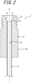
- the tip device 1 illustrated in FIGS. 1 to 4 forms a tip container set 3 by being combined with the container 2, illustrated in FIGS. 5 to 7 , that houses the tip device 1, and forms a tip electrode apparatus 5 by being combined with the electrode apparatus 4 illustrated in FIGS. 8 and 9 .
- the applications of the tip device 1 are not, however, limited to use in combination with the container 2 and the electrode apparatus 4.
- the tip device 1 includes a tubular tip 6 and a base 8 that is continuous with a rear end 6a of the tip 6 and that includes a base connector 7a as a first connector.
- the base connector 7a detachably connects to a container connector 7b as a second connector provided in the container 2 to house the tip 6.
- the base connector 7a detachably connects to a holder connector 7c as a second connector provided in an electrode holder 10.
- a linear electrode 9 to be introduced into the rear end 6a of the tip 6 protrudes from the electrode holder 10.
- the tip 6 is formed as a nano-tip with a head 6b having a nanometer-order inner diameter, but this configuration is not limiting.
- the head 6b of the tip 6 has an inner diameter of 100 nm, for example.
- the tip 6 is cylindrical, centered on an axial center O, with the head 6b gradually decreasing in diameter towards the end, but this configuration is not limiting.
- the tip 6 is, for example, formed of glass.
- the base 8 is made of synthetic resin, for example, and is adhered to the rear end 6a of the tip 6 by appropriate means, for example.
- means for adhering include adhesion, friction-based engagement, concavo-convex engagement, welding, and insert molding.
- the base 8 is a square cylinder centered on the axial center O, but this configuration is not limiting.
- the base 8 is provided so as to protrude farther towards the rear end than the rear end 6a of the tip 6, but this configuration is not limiting.
- the base 8 is located between the base connector 7a and the head 6b of the tip 6 and includes a grip 11 that is wider in the radial direction of the tip 6, but this configuration is not limiting.
- the base 8 includes an access hole 12 that communicates with the rear end 6a of the tip 6, but this configuration is not limiting.
- the access hole 12 includes a guide face 13 that gradually narrows in diameter towards the rear end 6a of the tip 6, but this configuration is not limiting.
- the guide face 13 is conical, but this configuration is not limiting.
- the front edge of the guide face 13 coincides with the back edge of an inner peripheral surface 6c of the tip 6, but this configuration is not limiting.
- the base 8 includes a grounding portion 14 configured to maintain the head 6b of the tip 6 separated from a flat surface S on which the tip 6 is placed, but this configuration is not limiting.
- the grounding portion 14 is located on the outer peripheral surface 8a of the base 8, but this configuration is not limiting.
- the base 8 is a rectangular column including the outer peripheral surface 8a, which has four flat faces that can each serve as the grounding portion 14, but this configuration is not limiting.
- the grounding portion 14 is not limited to being a flat surface but can also be curved, for example.
- the center of gravity of the base 8 can be appropriately set so that when the grounding portion 14 is placed in contact with the surface S, the head 6b of the tip 6 is kept separated from the surface S.
- the base connector 7a and the container connector 7b or holder connector 7c are configured to be connected by concavo-convex engagement, but this configuration is not limiting.
- these connectors may be configured to be connected by friction-based engagement.
- the base connector 7a and the container connector 7b or holder connector 7c are configured to be connected by screwing, but this configuration is not limiting.
- these connectors may be configured to be connected by concavo-convex engagement other than screwing.
- the container 2 includes a communication hole 15 through which the exterior of the container 2 communicates with the rear end 6a of the tip 6, but this configuration is not limiting.
- the communication hole 15 is concentric with the axial center O of the tip 6, but this configuration is not limiting.
- the container 2 includes a cap 16, which includes the container connector 7b, and a container body 17 including an opening 17a that detachably connects to the cap 16, but this configuration is not limiting.
- the container 2 is, for example, formed from synthetic resin.
- the cap 16 includes a cylindrical tube wall 16a centered on the axial center O and an annular flange 16b extending radially outward from the upper end of the tube wall 16a, but this configuration is not limiting.
- the lower end of the inner peripheral surface 16c of the tube wall 16a forms the container connector 7b.
- the remainder of the inner peripheral surface 16c of the tube wall 16a forms the communication hole 15.
- the tube wall 16a is cylindrical, but this configuration is not limiting, and the tube wall 16a may be a non-cylindrical tube.
- the flange 16b is circular, but this configuration is not limiting, and the flange 16b may be a non-circular ring.
- the up-down direction refers to the direction along the axial center O
- upward refers to the direction from the head 6b of the tip 6 to the rear end 6a of the tip 6 (i.e., upward in FIGS. 5 and 10 )
- downward refers to the opposite direction.
- the outer peripheral surface of the tube wall 16a detachably connects to the inner peripheral surface 17b of the opening 17a, but this configuration is not limiting.
- the outer peripheral surface of the tube wall 16a is configured to be connected by concavo-convex engagement to the inner peripheral surface 17b of the opening 17a, but this configuration is not limiting.
- these surfaces may be configured to be connected by friction-based engagement.
- the outer peripheral surface of the tube wall 16a is configured to be connected by screwing to the inner peripheral surface 17b of the opening 17a, but this configuration is not limiting.
- these surfaces may be configured to be connected by concavo-convex engagement other than screwing.
- the opening 17a of the container body 17 is cylindrical, but this configuration is not limiting, and the opening 17a may be a non-cylindrical tube.
- a torso 17c that surrounds the tip device 1 is connected to the opening 17a.
- the torso 17c has a bottomed cylindrical shape extending downward from the lower end of the opening 17a, but this configuration is not limiting.
- the shape of the torso 17c is not limited to a bottomed cylindrical shape.
- the torso 17c has a bottomed cylindrical shape, but this configuration is not limiting, and the torso 17c may have a bottomed tubular shape other than a bottomed cylindrical shape.
- the tip electrode apparatus 5 includes the tip device 1 and the electrode apparatus 4.
- the electrode apparatus 4 includes the electrode holder 10, which includes the holder connector 7c, and the linear electrode 9 that protrudes from the electrode holder 10 and is introduced into the rear end 6a of the tip 6.
- the electrode 9 is, for example, formed from a metal such as silver.
- the electrode holder 10 is, for example, formed from synthetic resin.
- the electrode holder 10 includes a downward opening recess 10a concentric with the axial center O of the tip 6, but this configuration is not limiting.
- the electrode 9 protrudes downward from an upper end face 10b of the recess 10a concentrically with the axial center O, but this configuration is not limiting.
- the holder connector 7c is configured by an inner peripheral surface 10c of the recess 10a, but this configuration is not limiting.
- the electrode 9 extends to the head-side portion of the tip 6 with the base connector 7a and the holder connector 7c in a connected state, but this configuration is not limiting.
- the tip 6 is filled with a liquid L, and the head 9a of the electrode 9 is immersed in the liquid L.
- the liquid L fills the head 6b of the tip 6 without any gaps, i.e., without any air bubbles.
- the amount of liquid L and the length of the electrode 9 can be changed as needed.
- the recess 10a is formed in the head 10d of the electrode holder 10, but this configuration is not limiting.
- the head 10d of the electrode holder 10 is cylindrical, but this configuration is not limiting, and the head 10d may be a non-cylindrical tube.
- the tip device 1 is used as follows for purposes such as measurement, injection, or collection of cells or other such samples, but this configuration is not limiting.
- the tip device 1 is distributed, sold, and stored while housed in the container 2, as illustrated in FIG. 5 .
- the liquid L is introduced from the rear end 6a of the tip 6 using a pipette, for example, while the tip device 1 remains in this state. That is, by insertion of the pipette into the rear end 6a of the tip 6 through the communication hole 15 and the access hole 12, the liquid L is introduced into the tip 6.
- the pipette can be guided into the rear end 6a of the tip 6 by the guide face 13 of the access hole 12.
- the tip container set 3 is centrifuged.
- the cap 16 of the container 2 is opened, and the tip device 1 is removed from the cap 16.
- the removed tip device 1 is placed on the surface S via the grounding portion 14, as illustrated in FIG. 4 , and the head 6b of the tip 6 is observed under a microscope. At this time, the head 6b of the tip 6 is kept separated from the surface S, so that contamination of the head 6b of the tip 6 can be easily controlled.
- the tip device 1 is again attached to the cap 16, the cap 16 is closed, and the tip container set 3 is placed back in the centrifuge.
- the tip device 1 can easily be inserted into and removed from the container 2 via the base connector 7a and the container connector 7b. Furthermore, the operation to insert and remove the tip device 1 into and from the container 2 can be performed easily by gripping the grip 11 with a finger, for example.
- the tip device 1 is attached to the electrode apparatus 4 as illustrated in FIG. 8 . That is, the electrode 9 is inserted into the rear end 6a of the tip 6 through the access hole 12, and the tip device 1 is attached to the electrode holder 10 via the base connector 7a and the holder connector 7c. At this time, the electrode 9 can be guided into the rear end 6a of the tip 6 by the guide face 13 of the access hole 12. The head 6b of the tip 6 is then immersed in a sample, and an electric field is applied between the sample and the electrode 9 to achieve the various purposes described above.
- the tip device 1 can easily be inserted into and removed from the electrode apparatus 4 via the base connector 7a and the holder connector 7c. Furthermore, the operation to insert and remove the tip device 1 into and from the electrode apparatus 4 can be performed easily by gripping the grip 11 with a finger, for example.
- the tip device 1 of the present embodiment not only can the operation of inserting and removing the tip 6 into and from the container 2 and electrode holder 10 be completed quickly, but also the occurrence of tip damage due to mishandling at the time of insertion and removal, and the resulting need for repeated operations, can be reduced. Accordingly, the efficiency of a series of operations for achieving the various objectives described above can be dramatically increased.
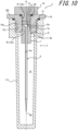
- the tip device 1 according to the embodiment described above can also be combined with the container 2 according to another embodiment illustrated in FIGS. 10 and 11 to configure the tip container set 3 according to another embodiment.
- FIGS. 10 and 11 elements corresponding to those in the embodiment described above are labeled with the same reference signs.
- An annular first sealing member 20 is further provided between the communication hole 15 and the blocking cap 19, but this configuration is not limiting.
- the first sealing member 20 is held by the blocking cap 19, but this configuration is not limiting.
- the first sealing member 20 may be held by the cap 16.
- An annular second sealing member 21 is further provided between the cap 16 and the opening 17a, but this configuration is not limiting.
- the second sealing member 21 may be held by either the cap 16 or the opening 17a.
- the tip container set 3 is distributed, sold, and stored, for example, while housing the tip device 1 and with the container 2 filled with a desired fluid, such as the liquid L.
- the tip container set 3 can, for example, also be used for the same purposes and in the same manner as in the embodiments described above by removing the blocking cap 19 from the cap 16.
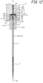
- the tip device 1 according to the embodiment described above can also be combined with the electrode apparatus 4 according to another embodiment illustrated in FIGS. 12 and 13 to configure the tip electrode apparatus 5 according to another embodiment.
- FIGS. 12 and 13 elements corresponding to those in the embodiment described above are labeled with the same reference signs.
- the electrode holder 10 includes an electrode terminal 22 as a first terminal continuous with the rear end of the electrode 9 and a holder terminal 23 as a second terminal that detachably contacts the first terminal.
- the electrode 9 is combined with the electrode terminal 22 to configure an electrode device 24.
- the tip device 1 is combined with the electrode device 24 to configure a tip electrode set 25.
- FIG. 12 illustrates the state in which connection between the base connector 7a and the holder connector 7c is completed, and the electrode terminal 22 and holder terminal 23 are in contact with each other.
- FIG. 13 illustrates a state during the transition from the connected state to the disconnected state between the base connector 7a and the holder connector 7c, in which the electrode terminal 22 and the holder terminal 23 are disconnected from each other.
- the electrode terminal 22 and the holder terminal 23 are, for example, each formed from a metal such as silver.
- the electrode device 24 may be distributed, sold, and stored together with or separately from the tip device 1 or the tip container set 3 (such as the one illustrated in FIG. 5 or FIG. 10 ).
- the electrode terminal 22 includes a contact portion 22a arranged on the rear end face of the base 8 and a shaft 22b that connects the contact portion 22a to the electrode 9, but this configuration is not limiting.
- the contact portion 22a of the electrode terminal 22 is disc-shaped and centered on the axial center O, but this configuration is not limiting.
- the shaft 22b of the electrode terminal 22 is a cylindrical column centered on the axial center O, but this configuration is not limiting.
- the rear end of the electrode 9 is connected to the head of the shaft 22b, but this configuration is not limiting.
- the holder terminal 23 includes a contact portion 23a arranged on the upper end face 10b of the recess 10a in the electrode holder 10 and a shaft 23b that is disposed within a recess communication hole 10e communicating with the recess 10a and is connected to the contact portion 23a, but this configuration is not limiting.
- the contact portion 23a of the holder terminal 23 is disc-shaped and centered on the axial center O, but this configuration is not limiting.
- the shaft 23b of the holder terminal 23 is a cylindrical column centered on the axial center O, but this configuration is not limiting.
- the recess communication hole 10e is formed by a cylindrical inner peripheral surface centered on the axial center O, but this configuration is not limiting.
- the electrode device 24 is, for example, disposed in the tip device 1 after the liquid L is introduced into the tip 6 of the tip device 1.
- the base connector 7a is connected to the holder connector 7c so that the contact portion 22a of the electrode terminal 22 and the contact portion 23a of the holder terminal 23 are sandwiched between the rear end face (upper end face) of the base 8 and the upper end face 10b of the recess 10a to be in contact with each other.
- This contact between the electrode terminal 22 and the holder terminal 23 enables the application of an electric field between the sample and the electrode 9.
- the base connector 7a being disconnected from the holder connector 7c, the contact portion 22a of the electrode terminal 22 and the contact portion 23a of the holder terminal 23 can be detached from each other. Therefore, when the tip device 1 held in the electrode holder 10 is replaced, the electrode device 24 can also be replaced. Accordingly, liquid L that was attached to the electrode 9 before replacement of the tip device 1 can be prevented from mixing with the liquid L in the tip device 1 after the replacement. This effect is particularly noticeable in a case in which the tip devices 1 before and after replacement hold different types of liquid L from each other.
- the above embodiment includes the following aspects:
- the tip device comprises a tubular tip; and a base that is continuous with a rear end of the tip and includes a first connector, wherein the first connector detachably connects to a second connector provided in a container to house the tip.
- the tip container set comprises a tubular tip; a base that is continuous with a rear end of the tip and includes a first connector; and a container configured to house the tip and including a second connector that detachably connects to the first connector.
- the container may include a communication hole through which an exterior of the container communicates with the rear end of the tip.
- the container may include a cap and a container body, the cap including the second connector, and the container body including an opening that detachably connects to the cap.
- the base may be located between the first connector and a head of the tip and includes a grip that is wider in a radial direction of the tip.
- the base may include an access hole that communicates with the rear end of the tip.
- the access hole may include a guide face that gradually narrows in diameter towards the rear end of the tip.
Landscapes
- Health & Medical Sciences (AREA)
- Chemical & Material Sciences (AREA)
- Clinical Laboratory Science (AREA)
- Chemical Kinetics & Catalysis (AREA)
- Life Sciences & Earth Sciences (AREA)
- Wood Science & Technology (AREA)
- Zoology (AREA)
- Bioinformatics & Cheminformatics (AREA)
- Organic Chemistry (AREA)
- General Health & Medical Sciences (AREA)
- Engineering & Computer Science (AREA)
- Microbiology (AREA)
- Molecular Biology (AREA)
- Sustainable Development (AREA)
- Biochemistry (AREA)
- General Engineering & Computer Science (AREA)
- Biotechnology (AREA)
- Genetics & Genomics (AREA)
- Biomedical Technology (AREA)
- Analytical Chemistry (AREA)
- Hematology (AREA)
- Apparatus Associated With Microorganisms And Enzymes (AREA)
- Sampling And Sample Adjustment (AREA)
- Packaging Of Annular Or Rod-Shaped Articles, Wearing Apparel, Cassettes, Or The Like (AREA)
Applications Claiming Priority (4)
| Application Number | Priority Date | Filing Date | Title |
|---|---|---|---|
| JP2019213560 | 2019-11-26 | ||
| JP2020070048A JP7367596B2 (ja) | 2019-11-26 | 2020-04-08 | チップデバイス、チップ容器セット、チップ電極装置及びチップ電極セット |
| EP20893903.3A EP4067471A4 (de) | 2019-11-26 | 2020-10-16 | Spitzenvorrichtung, spitzenbehältersatz, spitzenelektrodenvorrichtung und spitzenelektrodensatz |
| PCT/JP2020/039180 WO2021106422A1 (ja) | 2019-11-26 | 2020-10-16 | チップデバイス、チップ容器セット、チップ電極装置及びチップ電極セット |
Related Parent Applications (1)
| Application Number | Title | Priority Date | Filing Date |
|---|---|---|---|
| EP20893903.3A Division EP4067471A4 (de) | 2019-11-26 | 2020-10-16 | Spitzenvorrichtung, spitzenbehältersatz, spitzenelektrodenvorrichtung und spitzenelektrodensatz |
Publications (2)
| Publication Number | Publication Date |
|---|---|
| EP4450607A2 true EP4450607A2 (de) | 2024-10-23 |
| EP4450607A3 EP4450607A3 (de) | 2025-03-05 |
Family
ID=76129529
Family Applications (2)
| Application Number | Title | Priority Date | Filing Date |
|---|---|---|---|
| EP24197295.9A Pending EP4450607A3 (de) | 2019-11-26 | 2020-10-16 | Spitzenvorrichtung, spitzenbehältersatz, spitzenelektrodenvorrichtung und spitzenelektrodensatz |
| EP20893903.3A Withdrawn EP4067471A4 (de) | 2019-11-26 | 2020-10-16 | Spitzenvorrichtung, spitzenbehältersatz, spitzenelektrodenvorrichtung und spitzenelektrodensatz |
Family Applications After (1)
| Application Number | Title | Priority Date | Filing Date |
|---|---|---|---|
| EP20893903.3A Withdrawn EP4067471A4 (de) | 2019-11-26 | 2020-10-16 | Spitzenvorrichtung, spitzenbehältersatz, spitzenelektrodenvorrichtung und spitzenelektrodensatz |
Country Status (4)
| Country | Link |
|---|---|
| US (1) | US12059675B2 (de) |
| EP (2) | EP4450607A3 (de) |
| CN (1) | CN114746537A (de) |
| WO (1) | WO2021106422A1 (de) |
Citations (2)
| Publication number | Priority date | Publication date | Assignee | Title |
|---|---|---|---|---|
| JP2019213560A (ja) | 2004-12-08 | 2019-12-19 | ジェン−プローブ・インコーポレーテッド | 複数型のヒトパピローマウイルスに由来する核酸の検出 |
| JP2020070048A (ja) | 2018-10-30 | 2020-05-07 | 花王株式会社 | ポンプディスペンサー |
Family Cites Families (23)
| Publication number | Priority date | Publication date | Assignee | Title |
|---|---|---|---|---|
| JPH0352150Y2 (de) | 1986-05-07 | 1991-11-11 | ||
| US5431280A (en) | 1994-03-17 | 1995-07-11 | Humagen Fertility Diagnostics Inc. | Closure cap for holding pipets during shipping |
| US5977503A (en) * | 1997-11-03 | 1999-11-02 | Leach Thomas S. | Attachment device for electrical discharge machine |
| US7456012B2 (en) * | 1997-11-06 | 2008-11-25 | Cellectricon Ab | Method and apparatus for spatially confined electroporation |
| JPH11295282A (ja) | 1998-04-10 | 1999-10-29 | Rieko Naito | ピペット用チップ |
| DE19917375C2 (de) * | 1999-04-16 | 2001-09-27 | Hamilton Bonaduz Ag Bonaduz | Pipettiereinheit |
| JP3406860B2 (ja) * | 1999-04-21 | 2003-05-19 | 株式会社ソディック | 放電加工用パイプ電極ホルダ |
| JP2000342686A (ja) * | 1999-06-01 | 2000-12-12 | Terumo Corp | 医療用針および医療用具 |
| WO2003057819A1 (en) * | 2002-01-07 | 2003-07-17 | Uab Research Foundation | Electroporation cuvette-pipette tips, multi-well cuvette arrays, and electrode template apparatus adapted for automation and uses thereof |
| JP4767655B2 (ja) * | 2005-10-28 | 2011-09-07 | テルモ株式会社 | プロテクタ及び針セット |
| EP2863226A1 (de) | 2007-11-02 | 2015-04-22 | Humanix Co., Ltd. | Verfahren zum Einfangen von Flüssigkeit und zur Analyse von deren Bestandteilen sowie System zum Einfangen und zur Analyse von Flüssigkeit |
| US8274008B2 (en) * | 2008-10-15 | 2012-09-25 | Lam Research Corporation | EDM spindle assembly with fluid seal |
| US20110300621A1 (en) | 2009-12-10 | 2011-12-08 | Roche Molecular Systems, Inc. | Process head positioning |
| JPWO2012042904A1 (ja) * | 2010-09-30 | 2014-02-06 | パナソニック株式会社 | バイオセンサ収納体と、当該バイオセンサを用いる測定装置 |
| MX344792B (es) | 2011-09-25 | 2017-01-06 | Theranos Inc | Sistemas y métodos para múltiples análisis. |
| JP2015175837A (ja) * | 2014-03-18 | 2015-10-05 | ソニー株式会社 | ピペットチップ用板状部材、ピペットチップ、液体撹拌用キット及び液体撹拌装置 |
| EP3159395B1 (de) * | 2014-06-17 | 2018-05-30 | Yamaha Hatsudoki Kabushiki Kaisha | Zylinderspitzenmontagekopf und kopfvorrichtung sowie bewegungsvorrichtung damit |
| JP6090387B2 (ja) | 2014-12-15 | 2017-03-08 | 横河電機株式会社 | 細胞吸引システム及びこれを用いた細胞内物質の吸引作業を行う方法 |
| WO2017210334A1 (en) * | 2016-05-31 | 2017-12-07 | Massachusetts Institute Of Technology | Hydrodynamically controlled electric fields for high throughput transformation & high throughput parallel transformation platform |
| JP2018143999A (ja) | 2017-03-08 | 2018-09-20 | 株式会社アイカムス・ラボ | ピペットチップ、ピペットチップの成型金型及びピペットチップの成型方法 |
| JP6953888B2 (ja) | 2017-08-10 | 2021-10-27 | 横河電機株式会社 | 吸引システム、吸引方法及びプログラム |
| JP6444560B1 (ja) | 2018-08-30 | 2018-12-26 | 株式会社マイクロブラッドサイエンス | 血液採取器具 |
| CN221106122U (zh) * | 2023-07-19 | 2024-06-11 | 胡兴姬 | 一种生猪养殖用注射装置 |
-
2020
- 2020-10-16 US US17/755,759 patent/US12059675B2/en active Active
- 2020-10-16 EP EP24197295.9A patent/EP4450607A3/de active Pending
- 2020-10-16 WO PCT/JP2020/039180 patent/WO2021106422A1/ja not_active Ceased
- 2020-10-16 EP EP20893903.3A patent/EP4067471A4/de not_active Withdrawn
- 2020-10-16 CN CN202080082328.6A patent/CN114746537A/zh active Pending
Patent Citations (2)
| Publication number | Priority date | Publication date | Assignee | Title |
|---|---|---|---|---|
| JP2019213560A (ja) | 2004-12-08 | 2019-12-19 | ジェン−プローブ・インコーポレーテッド | 複数型のヒトパピローマウイルスに由来する核酸の検出 |
| JP2020070048A (ja) | 2018-10-30 | 2020-05-07 | 花王株式会社 | ポンプディスペンサー |
Also Published As
| Publication number | Publication date |
|---|---|
| EP4067471A4 (de) | 2024-06-26 |
| US20220387989A1 (en) | 2022-12-08 |
| EP4067471A1 (de) | 2022-10-05 |
| CN114746537A (zh) | 2022-07-12 |
| EP4450607A3 (de) | 2025-03-05 |
| US12059675B2 (en) | 2024-08-13 |
| WO2021106422A1 (ja) | 2021-06-03 |
Similar Documents
| Publication | Publication Date | Title |
|---|---|---|
| US11125709B2 (en) | Cartridge, kit comprising cartridge, electric measuring apparatus, and electric measuring method | |
| US4707337A (en) | Medical micro pipette tips for difficult to reach places and related methods | |
| US4690670A (en) | Centrifuge tube having reusable seal | |
| US3081029A (en) | Improved centrifuge tube | |
| CN105518446B (zh) | 电力迁移介质容器以及电力迁移装置 | |
| US20170350838A1 (en) | Electric measuring cartridge, biological sample electric measuring device, and biological sample electric measuring method | |
| US5310527A (en) | Tube for use in a pelleting centrifuge rotor | |
| EP1351767B1 (de) | Pipetten-spanndorn, vorrichtung und verfahren zur fixierung von pipettenspitzen am pippettenschaft | |
| KR20040077527A (ko) | 시약 용기를 자동 개방하기 위한 시스템 | |
| CN102325501B (zh) | 增强的用于收集、运输和提取粪便样品的试管 | |
| JPH0638945A (ja) | 採血器具のアダプター | |
| EP2612901A1 (de) | Mikrobenzählgerät, mikrobenzählvorrichtung damit und mirkobenzählverfahren damit | |
| US12059675B2 (en) | Tip device, tip container set, tip electrode apparatus, and tip electrode set | |
| JPWO2012066747A1 (ja) | 微生物数測定装置 | |
| JPH0126290B2 (de) | ||
| EP3845316A1 (de) | Applikationsnadelteil, applikationsnadelelementanordnung, applikationselement und applikationsvorrichtung | |
| JP2024119988A (ja) | 固相微量抽出デバイス、保管装置、および操作装置 | |
| CN114700122B (zh) | 用于电化学容器的封闭机构、电化学容器和实验室设备 | |
| CN110193388A (zh) | 一种多通道自动移液枪 | |
| JP7367596B2 (ja) | チップデバイス、チップ容器セット、チップ電極装置及びチップ電極セット | |
| US20200170626A1 (en) | Device for preparing a sample to be analyzed and method for preparing a sample to be analyzed | |
| WO2020115989A1 (ja) | コネクタ | |
| JP6816792B2 (ja) | 電気的測定用カートリッジ、並びに電気的測定装置及び電気的測定方法 | |
| US11311881B2 (en) | Fluid handling method, fluid handling device used in same, and fluid handling system | |
| HU203410B (en) | Container and apparatus for detecting microorganisms |
Legal Events
| Date | Code | Title | Description |
|---|---|---|---|
| PUAI | Public reference made under article 153(3) epc to a published international application that has entered the european phase |
Free format text: ORIGINAL CODE: 0009012 |
|
| STAA | Information on the status of an ep patent application or granted ep patent |
Free format text: STATUS: REQUEST FOR EXAMINATION WAS MADE |
|
| 17P | Request for examination filed |
Effective date: 20240829 |
|
| AC | Divisional application: reference to earlier application |
Ref document number: 4067471 Country of ref document: EP Kind code of ref document: P |
|
| AK | Designated contracting states |
Kind code of ref document: A2 Designated state(s): AL AT BE BG CH CY CZ DE DK EE ES FI FR GB GR HR HU IE IS IT LI LT LU LV MC MK MT NL NO PL PT RO RS SE SI SK SM TR |
|
| REG | Reference to a national code |
Ref country code: DE Ref legal event code: R079 Free format text: PREVIOUS MAIN CLASS: C12M0001420000 Ipc: C12M0001000000 |
|
| PUAL | Search report despatched |
Free format text: ORIGINAL CODE: 0009013 |
|
| AK | Designated contracting states |
Kind code of ref document: A3 Designated state(s): AL AT BE BG CH CY CZ DE DK EE ES FI FR GB GR HR HU IE IS IT LI LT LU LV MC MK MT NL NO PL PT RO RS SE SI SK SM TR |
|
| RIC1 | Information provided on ipc code assigned before grant |
Ipc: C12M 1/42 20060101ALI20250129BHEP Ipc: C12M 1/26 20060101ALI20250129BHEP Ipc: B01L 3/02 20060101ALI20250129BHEP Ipc: C12M 1/00 20060101AFI20250129BHEP |