EP4450398B1 - Anordnung für ein flugzeug, besagte anordnung mit einem mast und einem tank mit einem löschmittel - Google Patents
Anordnung für ein flugzeug, besagte anordnung mit einem mast und einem tank mit einem löschmittel Download PDFInfo
- Publication number
- EP4450398B1 EP4450398B1 EP24162461.8A EP24162461A EP4450398B1 EP 4450398 B1 EP4450398 B1 EP 4450398B1 EP 24162461 A EP24162461 A EP 24162461A EP 4450398 B1 EP4450398 B1 EP 4450398B1
- Authority
- EP
- European Patent Office
- Prior art keywords
- assembly
- support element
- support
- chassis
- fastening means
- Prior art date
- Legal status (The legal status is an assumption and is not a legal conclusion. Google has not performed a legal analysis and makes no representation as to the accuracy of the status listed.)
- Active
Links
Images

Classifications
-
- B—PERFORMING OPERATIONS; TRANSPORTING
- B64—AIRCRAFT; AVIATION; COSMONAUTICS
- B64D—EQUIPMENT FOR FITTING IN OR TO AIRCRAFT; FLIGHT SUITS; PARACHUTES; ARRANGEMENT OR MOUNTING OF POWER PLANTS OR PROPULSION TRANSMISSIONS IN AIRCRAFT
- B64D45/00—Aircraft indicators or protectors not otherwise provided for
-
- A—HUMAN NECESSITIES
- A62—LIFE-SAVING; FIRE-FIGHTING
- A62C—FIRE-FIGHTING
- A62C3/00—Fire prevention, containment or extinguishing specially adapted for particular objects or places
- A62C3/07—Fire prevention, containment or extinguishing specially adapted for particular objects or places in vehicles, e.g. in road vehicles
- A62C3/08—Fire prevention, containment or extinguishing specially adapted for particular objects or places in vehicles, e.g. in road vehicles in aircraft
-
- B—PERFORMING OPERATIONS; TRANSPORTING
- B64—AIRCRAFT; AVIATION; COSMONAUTICS
- B64D—EQUIPMENT FOR FITTING IN OR TO AIRCRAFT; FLIGHT SUITS; PARACHUTES; ARRANGEMENT OR MOUNTING OF POWER PLANTS OR PROPULSION TRANSMISSIONS IN AIRCRAFT
- B64D29/00—Power-plant nacelles, fairings or cowlings
- B64D29/02—Power-plant nacelles, fairings or cowlings associated with wings
-
- B—PERFORMING OPERATIONS; TRANSPORTING
- B64—AIRCRAFT; AVIATION; COSMONAUTICS
- B64D—EQUIPMENT FOR FITTING IN OR TO AIRCRAFT; FLIGHT SUITS; PARACHUTES; ARRANGEMENT OR MOUNTING OF POWER PLANTS OR PROPULSION TRANSMISSIONS IN AIRCRAFT
- B64D33/00—Arrangement in aircraft of power plant parts or auxiliaries not otherwise provided for
-
- F—MECHANICAL ENGINEERING; LIGHTING; HEATING; WEAPONS; BLASTING
- F02—COMBUSTION ENGINES; HOT-GAS OR COMBUSTION-PRODUCT ENGINE PLANTS
- F02C—GAS-TURBINE PLANTS; AIR INTAKES FOR JET-PROPULSION PLANTS; CONTROLLING FUEL SUPPLY IN AIR-BREATHING JET-PROPULSION PLANTS
- F02C7/00—Features, components parts, details or accessories, not provided for in, or of interest apart form groups F02C1/00 - F02C6/00; Air intakes for jet-propulsion plants
- F02C7/24—Heat or noise insulation
- F02C7/25—Fire protection or prevention
-
- A—HUMAN NECESSITIES
- A62—LIFE-SAVING; FIRE-FIGHTING
- A62C—FIRE-FIGHTING
- A62C35/00—Permanently-installed equipment
- A62C35/02—Permanently-installed equipment with containers for delivering the extinguishing substance
-
- B—PERFORMING OPERATIONS; TRANSPORTING
- B64—AIRCRAFT; AVIATION; COSMONAUTICS
- B64D—EQUIPMENT FOR FITTING IN OR TO AIRCRAFT; FLIGHT SUITS; PARACHUTES; ARRANGEMENT OR MOUNTING OF POWER PLANTS OR PROPULSION TRANSMISSIONS IN AIRCRAFT
- B64D45/00—Aircraft indicators or protectors not otherwise provided for
- B64D2045/009—Fire detection or protection; Erosion protection, e.g. from airborne particles
Definitions
- the present invention relates to an assembly for an aircraft, said assembly comprising a mast and a tank containing an extinguishing agent, as well as an aircraft comprising at least one such assembly.
- An aircraft typically comprises at least one nacelle inside which is arranged an engine, for example of the turbojet type.
- the nacelle and the engine are attached to the structure of the aircraft by means of a mast fixed under the wing of the aircraft.
- the aircraft is equipped with a fire-fighting system that consists of two tanks.
- FIG. 5 shows a state-of-the-art assembly 800 which comprises a mast 801 and two tanks 802 which are installed in the mast 801 and which each contain an extinguishing agent.
- Each tank 802 is here spherical and for each tank 802, the mast 801 has an opening 804 which passes through a side wall of the mast 801 and through which the tank 802 is introduced and fixed inside the mast 801.
- Each tank 802 is equipped with a discharge head 806 which includes a seal that closes the tank 802 and an explosive cartridge that destroys the seal when activated.
- the fire suppression system also includes a discharge pipe 808 that extends inside the mast 801 between the discharge head 806 and the engine. The destruction of the seal allows the release of the extinguishing agent which then flows or escapes in the discharge pipe 808 towards the engine.
- each first fixing means takes the form, at the proximal end, of a bolt comprising a first nut fixed to the frame and a first clamping screw which screws into the first nut through a first bore of the associated support element.
- each first clamping screw is accessible from inside the chassis between the support elements.
- each support element is achieved by providing a second fixing means which takes the form, at the distal end, of a bolt comprising a second nut fixed to the frame and a second clamping screw which screws into the second nut through a second bore in the support element.
- a second fixing means which takes the form, at the distal end, of a bolt comprising a second nut fixed to the frame and a second clamping screw which screws into the second nut through a second bore in the support element.
- the screw head of each second clamping screw is accessible from inside the frame between the support elements.
- the assembly comprises at the distal end of each support element, a first fixing means comprising a bolt with a first nut fixed to the frame and a first clamping screw which screws into the first nut through a first bore of the associated support element.
- the first fixing means is arranged below the second fixing means.
- each first support face is equipped with at least one step arranged so that in the installation position, a fixing means is located at the rear of a step relative to the downward direction of the first support face.
- the invention also proposes an aircraft comprising an assembly according to one of the preceding variants.
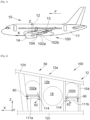
- FIG. 1 shows an aircraft 10 which comprises a fuselage 11 on each side of which is fixed a wing 13 which carries an engine 14 such as for example a dual-flow turbojet.
- the aircraft 10 also includes a mast 12 which ensures the attachment of the engine 14 under the wing 13.
- X the longitudinal direction of the mast which supports the engine and which is parallel to the longitudinal axis of the aircraft and oriented forwards
- Y the transverse direction which is horizontal when the aircraft is on the ground
- Z the vertical direction which is vertical when the aircraft is on the ground
- front and rear are to be considered in relation to a direction of advancement of the aircraft 10 during operation of the engine 14, this direction being represented schematically by the arrow F.
- the aircraft 10 comprises a fire-fighting system 100 which comprises at least one tank 102a-b filled with an extinguishing agent and, for each tank 102a-b, a discharge pipe 104 which extends between said tank 102a-b and the engine 14 supported by said mast 12.
- a fire-fighting system 100 which comprises at least one tank 102a-b filled with an extinguishing agent and, for each tank 102a-b, a discharge pipe 104 which extends between said tank 102a-b and the engine 14 supported by said mast 12.
- the tank 102a is equipped with a discharge head which is arranged to release the extinguishing agent to the discharge line 104 when needed.
- Figs. 2 to 4 show an assembly 50 according to the invention which comprises the mast 12 and at least one tank 102a-b. In the embodiment of the invention presented here, there are two tanks 102a-b, but the invention applies in the same way for a single tank 102a-b. In the remainder of the description, unless otherwise specified, reference is made to a single tank 102a.
- the mast 12 conventionally extends in the longitudinal direction X and comprises a structure consisting of a frame 12a and walls 12b fixed around the frame 12a.
- the mast 12 is generally symmetrical with respect to a vertical median plane XZ of the mast 12 which passes through the axis of the engine 14.
- the mast 12 takes the form of a box which comprises, among other things, a lower wall 12c, an upper wall 12d and two side walls 12b which are vertical and which extend on either side of the vertical median plane XZ of the mast 12.
- the frame 12a is here made up of several profiles 104 fixed to each other and on which the walls 12b-d are fixed.
- the two side walls 12b are thus fixed on either side of the frame 12a in planes which are generally vertical and parallel to the median plane.
- each profile 104 here takes the form of an arch which extends in a plane generally perpendicular to the longitudinal direction X and which comprises two posts 104a-b which are oriented vertically and arranged on either side of the median plane XZ.
- the posts 104a-b are thus spaced apart from each other to allow free passage between them for the tank 102a.
- the frame 12a is open to allow the tank 102a to pass between the elements which constitute said frame 12a.
- Each side wall 12b is pierced with an opening 18 (seen in the background on the Fig. 2 ) which allows access to the interior of the mast 12 and the chassis 12a from the exterior of the mast 12 and the opening 18 is sized to allow the passage of the tank 102a.
- the two openings 18 are arranged opposite each other with respect to the median plane XZ.
- the tank 102a is equipped with the fixing means 106 which are arranged on either side of the median plane XZ when the tank 102a is in place. As explained below, when the tank 102a is placed in the mast 12 through the opening 18, the fixing means 106 are accessible from each opening 18.
- the fixing means 106 are here tabs and they cooperate with fixing elements 108 to ensure the fixing of the tank 102a inside the mast 12 when the tank 102a is in place.
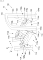
- the assembly 50 also comprises a support 111a-b which is mounted inside the frame 12a, here between two neighboring arches. Of course, when there are several tanks 102a-b, there is one support 111a-b per tank 102a-b.
- the support 111a-b comprises two support elements 110a-b, each extending here parallel to the longitudinal direction X.
- Each support element 110a-b here has a first bearing face 113 oriented upwards and each fixing means 106 bears on a first bearing face 113 by a second bearing face which it has and which is oriented downwards.
- each second bearing face bears against a first bearing face 113.
- the fixing elements 108 ensure the fixing of the fixing means 106 of the tank 102a to a support element 110a-b and each takes for example the form of a screw which screws into the support element 110a-b in a bore provided for this purpose by passing through the fixing means 106.
- the support 111a-b is offset along the longitudinal direction X relative to the openings 18, and as shown in Fig. 2 , there is a support 111a which is forward relative to the openings 18 and a support 111b which is rearward relative to the openings 18. It is thus possible to arrange a reservoir 102a in front of the openings 18 and one at the rear.
- Each support element 110a-b has a proximal end 112a which is on the side of the openings 18 and a distal end 112b which is on the side opposite said openings 18.
- the support 111a has its proximal ends 112a towards the rear and its distal ends 112b towards the front
- the support 111b has its proximal ends 112a towards the front and its distal ends 112b towards the rear.
- Each proximal end 112a is fixed to the frame 12a, here to one of the two posts 104a-b constituting a profile 104, by at least one first fixing means 114 which ensures removable fixing of the proximal end 110a to the frame 12a.
- first fastening means 114 per proximal end 112a to provide redundancy
- each here is a bolt comprising a first nut 114a fixed to the frame 12a and a first clamping screw 114b which screws into the first nut 114a through a first bore 114c of the support element 110a-b.
- the screw head of each first clamping screw 114b is accessible from inside the frame 12a between the support elements 110a-b so that the operator is not hindered by the side walls 12b.
- the heads of the first clamping screws 114b of one support element 110a-b are thus opposite the heads of the first clamping screws 114b of the other support element 110b-a.
- Each distal end 112b is mounted to rotate on the frame 12a around a horizontal axis of rotation 60 perpendicular to the longitudinal direction X.
- Each support element 110a-b is thus able to rotate alternately between a position of use ( Fig. 2 ) in which the first associated support face 113 is horizontal and in which the support element 110a-b is fixed by the first fixing means 114 and a positioning position ( Fig. 3 ) in which the first bearing face 113 is tilted downwards and in which the support element 110a-b is not fixed by the first fixing means 114.
- each first fixing means 114 is removed, to release the rotation of each support element 110a-b which, due to its weight, pivots downwards around the axis of rotation 60 as shown by the arrow 62 to arrive in the position of installation.
- the first bearing face 113 i.e. the top of the support element 110a-b
- Each support element 110a-b can then be raised into its position of use, i.e. with the first bearing face 113 in a horizontal position (in the opposite direction to the arrow 62), and each first fixing means 114 is put back in place to fix the position of the support element 110a-b.
- Removing a 102a-b tank is done in the same way.
- the assembly 50 comprises, for each support element 110a-b, a stop 120 against which the support element 110a-b bears in the installation position.
- a stop 120 against which the support element 110a-b bears in the installation position.
- it is the proximal end 112a of the support element 110a-b which bears against the stop 120, here by means of a tab in which the first bores 114c of the first fixing means 114 are made.
- the stop 120 takes the form of a fold of a fitting 122 secured to the frame 12a, here of a post 104a-b, where the fitting 122 also carries here the first nuts 114a of the first fixing means 114.
- each stop 120 is arranged so that in the installation position, the first support face 113 has an angle of 20° downwards with the horizontal.
- each support element 110a-b is achieved by placing at the distal end 112b of each support element 110a-b, a second fixing means 126 which takes the form of a bolt comprising a second nut 126a fixed to the frame 12a and a second clamping screw 126b which screws into the second nut 126a through a second bore of the support element 110a-b.
- the screw head of each second clamping screw 126b is also accessible from inside the frame 12a between the support elements 110a-b.
- the second clamping screw 126b In the use position, the second clamping screw 126b is tightened to help hold the support member 110a-b and in the installation position, the second clamping screw 126b is loosened but remains engaged with the second nut 126a to form a shaft about which the support member 110a-b pivots.
- the assembly 50 comprises at the distal end 112b of each support element 110a-b, a first fixing means 114, i.e. here, a bolt with a first nut 114a fixed to the frame 12a and a first clamping screw 114b which screws into the first nut 114a through a first bore 114c of the associated support element 110a-b.
- the first clamping screw 114b unscrews completely to be removed to allow rotation of the support member 110a-b.
- the first fixing means 114 is arranged below the second fixing means 126.
- each first bearing face 113 is equipped with at least one step 130.
- a fixing means 106 is located at the rear of a step 130 relative to the downward direction of the first bearing face 113 in the position of installation, to be blocked by the latter.
- each support element 110a-b comprises a lower beam 115a which comprises the first bores 114c and the second bore and an upper beam 115b fixed on the lower beam 115a by means of spacers and having the first bearing face 113.
Landscapes
- Engineering & Computer Science (AREA)
- Chemical & Material Sciences (AREA)
- Combustion & Propulsion (AREA)
- Aviation & Aerospace Engineering (AREA)
- Health & Medical Sciences (AREA)
- Public Health (AREA)
- Business, Economics & Management (AREA)
- Emergency Management (AREA)
- General Engineering & Computer Science (AREA)
- Mechanical Engineering (AREA)
- Connection Of Plates (AREA)
- Traffic Control Systems (AREA)
- Filling Or Discharging Of Gas Storage Vessels (AREA)
Claims (10)
- Anordnung (50) für ein Flugzeug (10), wobei die Anordnung (50) Folgendes umfasst:- einen Pylon (12), der sich entlang einer Längsrichtung (X) erstreckt und einen Rahmen (12a) und zwei Seitenwände (12b), die zu beiden Seiten des Rahmens (12a) angeordnet sind und jeweils über eine Öffnung (18) verfügen, umfasst,- mindestens einen Behälter (102a-b), der Befestigungsmittel (106) umfasst und dazu bestimmt ist, ein Löschmittel zu enthalten,- für jeden Behälter (102a-b) einen Träger (111a-b), der zwei Tragelemente (110a-b) umfasst, dadurch gekennzeichnet, dass jeder Träger (111a-b) in Bezug auf die Öffnungen (18) entlang der Längsrichtung (X) versetzt ist, wobei jedes Tragelement (110a-b) eine erste Anlagefläche (113) aufweist, die nach oben zeigt und auf der die Befestigungsmittel (106) anliegen, wobei jedes Tragelement (110a-b) ein proximales Ende (112a) auf der Seite der Öffnungen (18) und ein distales Ende (112b) auf der den Öffnungen (18) entgegengesetzten Seite aufweist, wobei jedes proximale Ende (112a) durch mindestens ein erstes Befestigungsmittel (114) an dem Rahmen (12a) befestigt ist, welches eine lösbare Befestigung des proximalen Endes (112a) gestattet, wobei jedes distale Ende (112b) um eine horizontale und zu der Längsrichtung (X) senkrechte Drehachse (60) drehbar an dem Rahmen (12a) angebracht ist und wobei jedes Tragelement (110a-b) zwischen einer Verwendungsposition, in der die assoziierte erste Anlagefläche (113) horizontal ist, und einer Einrichtungsposition, in der die erste Anlagefläche (113) nach unten geschwenkt ist, beweglich ist,- für jeden Behälter (102a-b) und für jedes Tragelement (110a-b) Befestigungselemente (108), die die Befestigung der Befestigungsmittel (106) des Behälters (102a-b) an dem Tragelement (110a-b) gewährleisten.
- Anordnung (50) nach Anspruch 1, dadurch gekennzeichnet, dass sie für jedes Tragelement (110a-b) einen Anschlag (120) umfasst, an dem das Tragelement (110a-b) in der Einrichtungsposition anliegt.
- Anordnung (50) nach einem der Ansprüche 1 oder 2, dadurch gekennzeichnet, dass jedes erste Befestigungsmittel (114) an dem proximalen Ende (112a) die Form eines Bolzens annimmt, der eine erste Mutter (114a), die an dem Rahmen (12a) befestigt ist, und eine erste Spannschraube (114b), die durch eine erste Bohrung (114c) des assoziierten Tragelements (110a-b) hindurch in die erste Mutter (114a) eingeschraubt wird, umfasst.
- Anordnung (50) nach Anspruch 3, dadurch gekennzeichnet, dass der Schraubenkopf jeder ersten Spannschraube (114b) von innerhalb des Rahmens (12a) zwischen den Tragelementen (110a-b) zugänglich ist.
- Anordnung (50) nach einem der Ansprüche 1 bis 4, dadurch gekennzeichnet, dass das Drehen jedes Tragelements (110a-b) durch das Einrichten eines zweiten Befestigungsmittels (126) verwirklicht wird, welches an dem distalen Ende (112b) die Form eines Bolzens annimmt, der eine zweite Mutter (126a), die an dem Rahmen (12a) befestigt ist, und eine zweite Spannschraube (126b), die durch eine zweite Bohrung des Tragelements (110a-b) hindurch in die zweite Mutter (126a) eingeschraubt wird, umfasst.
- Anordnung (50) nach Anspruch 5, dadurch gekennzeichnet, dass der Schraubenkopf jeder zweiten Spannschraube (126b) von innerhalb des Rahmens (12a) zwischen den Tragelementen (110a-b) zugänglich ist.
- Anordnung (50) nach einem der Ansprüche 5 oder 6, dadurch gekennzeichnet, dass sie an dem distalen Ende (112b) jedes Tragelements (110a-b) ein erstes Befestigungselement (114) umfasst, das einen Bolzen mit einer ersten Mutter (114a), die an dem Rahmen (12a) befestigt ist, und einer ersten Spannschraube (114b), die durch eine erste Bohrung (114c) des assoziierten Tragelements (110a-b) hindurch in die erste Mutter (114a) eingeschraubt wird, umfasst.
- Anordnung (50) nach Anspruch 7, dadurch gekennzeichnet, dass das erste Befestigungsmittel (114) an jedem distalen Ende (112b) unterhalb des zweiten Befestigungsmittels (126) angeordnet ist.
- Anordnung (50) nach einem der Ansprüche 1 bis 8, dadurch gekennzeichnet, dass jede erste Anlagefläche (113) mit mindestens einer Stufe (130) ausgerüstet ist, die so eingerichtet ist, dass sich ein Befestigungsmittel (106) in der Einrichtungsposition in Bezug auf die Abwärtsrichtung der ersten Anlagefläche (113) hinter einer Stufe (130) befindet.
- Flugzeug (10), das eine Anordnung (50) nach einem der vorhergehenden Ansprüche umfasst.
Applications Claiming Priority (1)
| Application Number | Priority Date | Filing Date | Title |
|---|---|---|---|
| FR2304025A FR3148009A1 (fr) | 2023-04-21 | 2023-04-21 | Ensemble pour un aéronef, ledit ensemble comportant un mat et un réservoir contenant un agent extincteur |
Publications (2)
| Publication Number | Publication Date |
|---|---|
| EP4450398A1 EP4450398A1 (de) | 2024-10-23 |
| EP4450398B1 true EP4450398B1 (de) | 2025-06-18 |
Family
ID=87555028
Family Applications (1)
| Application Number | Title | Priority Date | Filing Date |
|---|---|---|---|
| EP24162461.8A Active EP4450398B1 (de) | 2023-04-21 | 2024-03-08 | Anordnung für ein flugzeug, besagte anordnung mit einem mast und einem tank mit einem löschmittel |
Country Status (4)
| Country | Link |
|---|---|
| US (1) | US20240351704A1 (de) |
| EP (1) | EP4450398B1 (de) |
| CN (1) | CN118811102A (de) |
| FR (1) | FR3148009A1 (de) |
Families Citing this family (1)
| Publication number | Priority date | Publication date | Assignee | Title |
|---|---|---|---|---|
| FR3146461A1 (fr) * | 2023-03-09 | 2024-09-13 | Airbus Operations | Ensemble pour un aéronef, ledit ensemble comportant un mat et un réservoir contenant un fluide extincteur |
Family Cites Families (12)
| Publication number | Priority date | Publication date | Assignee | Title |
|---|---|---|---|---|
| FR2942969B1 (fr) * | 2009-03-10 | 2011-03-04 | Airbus France | Dispositif d'extinction d'incendies pour aeronef et procede de fixation |
| US11439854B2 (en) * | 2017-08-17 | 2022-09-13 | The Boeing Company | Common array mounting bottles engineered for reuse |
| CN111295230B (zh) * | 2017-11-03 | 2021-08-13 | 庞巴迪公司 | 飞机的灭火系统 |
| FR3094892B1 (fr) * | 2019-04-12 | 2022-07-01 | Airbus Operations Sas | Systeme anti-incendie pour un aeronef comportant un reservoir a double chambre |
| FR3099465B1 (fr) * | 2019-07-30 | 2022-12-02 | Airbus Operations Sas | Ensemble pour un aeronef, ledit ensemble comportant un mat et un reservoir contenant un fluide extincteur |
| FR3105177B1 (fr) * | 2019-12-18 | 2022-01-07 | Airbus Operations Sas | Ensemble pour un aeronef, ledit ensemble comportant un mat et un reservoir contenant un fluide extincteur |
| EP3945033B1 (de) * | 2020-07-27 | 2022-09-07 | Airbus Operations (S.A.S.) | Flugzeugantriebseinheit |
| EP3950507B1 (de) * | 2020-08-04 | 2023-11-08 | Airbus SAS | Montageverfahren für einen flugzeugmast und flugzeugmast erhalten durch dieses verfahren |
| FR3124793A1 (fr) * | 2021-07-02 | 2023-01-06 | Airbus Operations | Ensemble comportant une structure et un réservoir fixé à la structure et contenant un fluide extincteur |
| FR3139552A1 (fr) * | 2022-09-09 | 2024-03-15 | Airbus Operations (S.A.S.) | Mât d’aéronef équipé d’un système de guidage pour le montage ou démontage d’un réservoir et procédé de montage/démontage dudit réservoir |
| FR3146461A1 (fr) * | 2023-03-09 | 2024-09-13 | Airbus Operations | Ensemble pour un aéronef, ledit ensemble comportant un mat et un réservoir contenant un fluide extincteur |
| EP4480827A1 (de) * | 2023-06-14 | 2024-12-25 | Airbus Operations (S.A.S.) | Flugzeugantriebsanordnung mit strahltriebwerk, pylon und löschsystem |
-
2023
- 2023-04-21 FR FR2304025A patent/FR3148009A1/fr not_active Ceased
-
2024
- 2024-03-08 EP EP24162461.8A patent/EP4450398B1/de active Active
- 2024-04-05 US US18/627,739 patent/US20240351704A1/en active Pending
- 2024-04-18 CN CN202410465306.8A patent/CN118811102A/zh active Pending
Also Published As
| Publication number | Publication date |
|---|---|
| FR3148009A1 (fr) | 2024-10-25 |
| EP4450398A1 (de) | 2024-10-23 |
| CN118811102A (zh) | 2024-10-22 |
| US20240351704A1 (en) | 2024-10-24 |
Similar Documents
| Publication | Publication Date | Title |
|---|---|---|
| EP2500268B1 (de) | Aufhängesäule eines Flugzeugmotors | |
| CA2652317C (fr) | Dispositif d'accrochage d'un moteur d'aeronef | |
| EP2181037B1 (de) | Vorrichtung zur befestigung eines luftfahrzeugtriebwerks mit einer schubkraftsammelvorrichtung mit verminderten gesamtabmessungen | |
| EP2150462B1 (de) | Kopplungsmast eines flugzeugtriebwerks mit distanzstück zur befestigung der vordertriebwerksaufhängung | |
| EP2139768B1 (de) | Flugzeugmotorbefestigungspylon mit einer mit einer tonnenmutter versehenen hinteren motorbefestigung | |
| EP4450398B1 (de) | Anordnung für ein flugzeug, besagte anordnung mit einem mast und einem tank mit einem löschmittel | |
| FR2478572A1 (fr) | Installation de securite pour avions | |
| EP2139769A1 (de) | Befestigung für pylonkasten an flügeln, festklemmen einer seitenplatte des kastens | |
| WO2009147341A2 (fr) | Mat d'accrochage de moteur comprenant des moyens de fixation des longerons et des panneaux agences en dehors de l'espace interieur de caisson | |
| FR3099465A1 (fr) | Ensemble pour un aeronef, ledit ensemble comportant un mat et un reservoir contenant un fluide extincteur | |
| FR2931800A1 (fr) | Dispositif de reprise des efforts de poussee pour mat d'accrochage de moteur d'aeronef, comprenant des bielles laterales a butees de palonnier integrees | |
| FR3105177A1 (fr) | Ensemble pour un aeronef, ledit ensemble comportant un mat et un reservoir contenant un fluide extincteur | |
| CA2783706A1 (fr) | Mecanisme d'articulation frangible pour une cloison de plateforme, cloison, ensemble et procede associes | |
| FR2891526A1 (fr) | Mat d'accrochage de turboreacteur pour aeronef | |
| FR3012114A1 (fr) | Ensemble propulsif d'aeronef comportant une nacelle pourvue d'un mecanisme de verrouillage et de fermeture des capots | |
| FR3156756A1 (fr) | Ensemble propulsif pour aéronef comportant un moteur, un mât et des moyens d’accrochage du moteur au mât | |
| EP4428039B1 (de) | Anordnung für ein flugzeug, besagte anordnung mit einer matte und einem tank mit löschflüssigkeit | |
| FR3030442A1 (fr) | Pointe avant d'aeronef equipee d'un cadre de jonction entre la case de train d'atterrissage et la peau exterieure du fuselage | |
| EP4310005B1 (de) | Propellerantriebsanordnung für ein flugzeug | |
| FR3048226B1 (fr) | Aeronef a structure arriere modulaire | |
| FR3118757A1 (fr) | Structure secondaire avant d’un mat d’accrochage d’un aeronef | |
| FR3158310A1 (fr) | Ensemble pour le renfort du fuselage d’un aéronef lors du retrait d’un panneau amovible | |
| FR3043647A1 (fr) | Aeronef muni d'une soute amovible | |
| EP4497680B1 (de) | Flugzeug mit mindestens einem rohrförmigen speicherbehälter für ein löschfluid | |
| EP4442577B1 (de) | Reaktormast zur befestigung eines flugzeugmotors |
Legal Events
| Date | Code | Title | Description |
|---|---|---|---|
| PUAI | Public reference made under article 153(3) epc to a published international application that has entered the european phase |
Free format text: ORIGINAL CODE: 0009012 |
|
| STAA | Information on the status of an ep patent application or granted ep patent |
Free format text: STATUS: REQUEST FOR EXAMINATION WAS MADE |
|
| 17P | Request for examination filed |
Effective date: 20240311 |
|
| AK | Designated contracting states |
Kind code of ref document: A1 Designated state(s): AL AT BE BG CH CY CZ DE DK EE ES FI FR GB GR HR HU IE IS IT LI LT LU LV MC ME MK MT NL NO PL PT RO RS SE SI SK SM TR |
|
| GRAP | Despatch of communication of intention to grant a patent |
Free format text: ORIGINAL CODE: EPIDOSNIGR1 |
|
| STAA | Information on the status of an ep patent application or granted ep patent |
Free format text: STATUS: GRANT OF PATENT IS INTENDED |
|
| RIC1 | Information provided on ipc code assigned before grant |
Ipc: A62C 35/02 20060101ALN20250218BHEP Ipc: A62C 3/08 20060101ALN20250218BHEP Ipc: B64D 45/00 20060101ALN20250218BHEP Ipc: F02C 7/25 20060101ALI20250218BHEP Ipc: B64D 29/02 20060101AFI20250218BHEP |
|
| INTG | Intention to grant announced |
Effective date: 20250226 |
|
| GRAJ | Information related to disapproval of communication of intention to grant by the applicant or resumption of examination proceedings by the epo deleted |
Free format text: ORIGINAL CODE: EPIDOSDIGR1 |
|
| STAA | Information on the status of an ep patent application or granted ep patent |
Free format text: STATUS: REQUEST FOR EXAMINATION WAS MADE |
|
| GRAP | Despatch of communication of intention to grant a patent |
Free format text: ORIGINAL CODE: EPIDOSNIGR1 |
|
| STAA | Information on the status of an ep patent application or granted ep patent |
Free format text: STATUS: GRANT OF PATENT IS INTENDED |
|
| GRAS | Grant fee paid |
Free format text: ORIGINAL CODE: EPIDOSNIGR3 |
|
| INTC | Intention to grant announced (deleted) | ||
| GRAA | (expected) grant |
Free format text: ORIGINAL CODE: 0009210 |
|
| STAA | Information on the status of an ep patent application or granted ep patent |
Free format text: STATUS: THE PATENT HAS BEEN GRANTED |
|
| INTG | Intention to grant announced |
Effective date: 20250506 |
|
| RIC1 | Information provided on ipc code assigned before grant |
Ipc: A62C 35/02 20060101ALN20250429BHEP Ipc: A62C 3/08 20060101ALN20250429BHEP Ipc: B64D 45/00 20060101ALN20250429BHEP Ipc: F02C 7/25 20060101ALI20250429BHEP Ipc: B64D 29/02 20060101AFI20250429BHEP |
|
| AK | Designated contracting states |
Kind code of ref document: B1 Designated state(s): AL AT BE BG CH CY CZ DE DK EE ES FI FR GB GR HR HU IE IS IT LI LT LU LV MC ME MK MT NL NO PL PT RO RS SE SI SK SM TR |
|
| REG | Reference to a national code |
Ref country code: GB Ref legal event code: FG4D Free format text: NOT ENGLISH |
|
| REG | Reference to a national code |
Ref country code: CH Ref legal event code: EP |
|
| REG | Reference to a national code |
Ref country code: DE Ref legal event code: R096 Ref document number: 602024000206 Country of ref document: DE |
|
| REG | Reference to a national code |
Ref country code: CH Ref legal event code: EP |
|
| REG | Reference to a national code |
Ref country code: IE Ref legal event code: FG4D Free format text: LANGUAGE OF EP DOCUMENT: FRENCH |
|
| PG25 | Lapsed in a contracting state [announced via postgrant information from national office to epo] |
Ref country code: FI Free format text: LAPSE BECAUSE OF FAILURE TO SUBMIT A TRANSLATION OF THE DESCRIPTION OR TO PAY THE FEE WITHIN THE PRESCRIBED TIME-LIMIT Effective date: 20250618 |
|
| REG | Reference to a national code |
Ref country code: LT Ref legal event code: MG9D |
|
| PG25 | Lapsed in a contracting state [announced via postgrant information from national office to epo] |
Ref country code: GR Free format text: LAPSE BECAUSE OF FAILURE TO SUBMIT A TRANSLATION OF THE DESCRIPTION OR TO PAY THE FEE WITHIN THE PRESCRIBED TIME-LIMIT Effective date: 20250919 Ref country code: NO Free format text: LAPSE BECAUSE OF FAILURE TO SUBMIT A TRANSLATION OF THE DESCRIPTION OR TO PAY THE FEE WITHIN THE PRESCRIBED TIME-LIMIT Effective date: 20250918 |
|
| PG25 | Lapsed in a contracting state [announced via postgrant information from national office to epo] |
Ref country code: BG Free format text: LAPSE BECAUSE OF FAILURE TO SUBMIT A TRANSLATION OF THE DESCRIPTION OR TO PAY THE FEE WITHIN THE PRESCRIBED TIME-LIMIT Effective date: 20250618 |
|
| PG25 | Lapsed in a contracting state [announced via postgrant information from national office to epo] |
Ref country code: HR Free format text: LAPSE BECAUSE OF FAILURE TO SUBMIT A TRANSLATION OF THE DESCRIPTION OR TO PAY THE FEE WITHIN THE PRESCRIBED TIME-LIMIT Effective date: 20250618 |
|
| PG25 | Lapsed in a contracting state [announced via postgrant information from national office to epo] |
Ref country code: RS Free format text: LAPSE BECAUSE OF FAILURE TO SUBMIT A TRANSLATION OF THE DESCRIPTION OR TO PAY THE FEE WITHIN THE PRESCRIBED TIME-LIMIT Effective date: 20250918 |
|
| REG | Reference to a national code |
Ref country code: NL Ref legal event code: MP Effective date: 20250618 |
|
| PG25 | Lapsed in a contracting state [announced via postgrant information from national office to epo] |
Ref country code: LV Free format text: LAPSE BECAUSE OF FAILURE TO SUBMIT A TRANSLATION OF THE DESCRIPTION OR TO PAY THE FEE WITHIN THE PRESCRIBED TIME-LIMIT Effective date: 20250618 |
|
| PG25 | Lapsed in a contracting state [announced via postgrant information from national office to epo] |
Ref country code: NL Free format text: LAPSE BECAUSE OF FAILURE TO SUBMIT A TRANSLATION OF THE DESCRIPTION OR TO PAY THE FEE WITHIN THE PRESCRIBED TIME-LIMIT Effective date: 20250618 |
|
| PG25 | Lapsed in a contracting state [announced via postgrant information from national office to epo] |
Ref country code: PT Free format text: LAPSE BECAUSE OF FAILURE TO SUBMIT A TRANSLATION OF THE DESCRIPTION OR TO PAY THE FEE WITHIN THE PRESCRIBED TIME-LIMIT Effective date: 20251020 |
|
| REG | Reference to a national code |
Ref country code: AT Ref legal event code: MK05 Ref document number: 1803996 Country of ref document: AT Kind code of ref document: T Effective date: 20250618 |
|
| PG25 | Lapsed in a contracting state [announced via postgrant information from national office to epo] |
Ref country code: IS Free format text: LAPSE BECAUSE OF FAILURE TO SUBMIT A TRANSLATION OF THE DESCRIPTION OR TO PAY THE FEE WITHIN THE PRESCRIBED TIME-LIMIT Effective date: 20251018 |
|
| PG25 | Lapsed in a contracting state [announced via postgrant information from national office to epo] |
Ref country code: AT Free format text: LAPSE BECAUSE OF FAILURE TO SUBMIT A TRANSLATION OF THE DESCRIPTION OR TO PAY THE FEE WITHIN THE PRESCRIBED TIME-LIMIT Effective date: 20250618 Ref country code: SM Free format text: LAPSE BECAUSE OF FAILURE TO SUBMIT A TRANSLATION OF THE DESCRIPTION OR TO PAY THE FEE WITHIN THE PRESCRIBED TIME-LIMIT Effective date: 20250618 |
|
| PG25 | Lapsed in a contracting state [announced via postgrant information from national office to epo] |
Ref country code: CZ Free format text: LAPSE BECAUSE OF FAILURE TO SUBMIT A TRANSLATION OF THE DESCRIPTION OR TO PAY THE FEE WITHIN THE PRESCRIBED TIME-LIMIT Effective date: 20250618 |
|
| PG25 | Lapsed in a contracting state [announced via postgrant information from national office to epo] |
Ref country code: PL Free format text: LAPSE BECAUSE OF FAILURE TO SUBMIT A TRANSLATION OF THE DESCRIPTION OR TO PAY THE FEE WITHIN THE PRESCRIBED TIME-LIMIT Effective date: 20250618 |
|
| PG25 | Lapsed in a contracting state [announced via postgrant information from national office to epo] |
Ref country code: EE Free format text: LAPSE BECAUSE OF FAILURE TO SUBMIT A TRANSLATION OF THE DESCRIPTION OR TO PAY THE FEE WITHIN THE PRESCRIBED TIME-LIMIT Effective date: 20250618 |
|
| PG25 | Lapsed in a contracting state [announced via postgrant information from national office to epo] |
Ref country code: SK Free format text: LAPSE BECAUSE OF FAILURE TO SUBMIT A TRANSLATION OF THE DESCRIPTION OR TO PAY THE FEE WITHIN THE PRESCRIBED TIME-LIMIT Effective date: 20250618 |
|
| PG25 | Lapsed in a contracting state [announced via postgrant information from national office to epo] |
Ref country code: ES Free format text: LAPSE BECAUSE OF FAILURE TO SUBMIT A TRANSLATION OF THE DESCRIPTION OR TO PAY THE FEE WITHIN THE PRESCRIBED TIME-LIMIT Effective date: 20250618 |