EP4428039B1 - Anordnung für ein flugzeug, besagte anordnung mit einer matte und einem tank mit löschflüssigkeit - Google Patents
Anordnung für ein flugzeug, besagte anordnung mit einer matte und einem tank mit löschflüssigkeit Download PDFInfo
- Publication number
- EP4428039B1 EP4428039B1 EP24159746.7A EP24159746A EP4428039B1 EP 4428039 B1 EP4428039 B1 EP 4428039B1 EP 24159746 A EP24159746 A EP 24159746A EP 4428039 B1 EP4428039 B1 EP 4428039B1
- Authority
- EP
- European Patent Office
- Prior art keywords
- assembly
- carriage
- cradle
- reservoir
- frame
- Prior art date
- Legal status (The legal status is an assumption and is not a legal conclusion. Google has not performed a legal analysis and makes no representation as to the accuracy of the status listed.)
- Active
Links
Images


Classifications
-
- B—PERFORMING OPERATIONS; TRANSPORTING
- B64—AIRCRAFT; AVIATION; COSMONAUTICS
- B64D—EQUIPMENT FOR FITTING IN OR TO AIRCRAFT; FLIGHT SUITS; PARACHUTES; ARRANGEMENT OR MOUNTING OF POWER PLANTS OR PROPULSION TRANSMISSIONS IN AIRCRAFT
- B64D29/00—Power-plant nacelles, fairings or cowlings
- B64D29/02—Power-plant nacelles, fairings or cowlings associated with wings
-
- A—HUMAN NECESSITIES
- A62—LIFE-SAVING; FIRE-FIGHTING
- A62C—FIRE-FIGHTING
- A62C3/00—Fire prevention, containment or extinguishing specially adapted for particular objects or places
- A62C3/07—Fire prevention, containment or extinguishing specially adapted for particular objects or places in vehicles, e.g. in road vehicles
- A62C3/08—Fire prevention, containment or extinguishing specially adapted for particular objects or places in vehicles, e.g. in road vehicles in aircraft
-
- A—HUMAN NECESSITIES
- A62—LIFE-SAVING; FIRE-FIGHTING
- A62C—FIRE-FIGHTING
- A62C35/00—Permanently-installed equipment
- A62C35/02—Permanently-installed equipment with containers for delivering the extinguishing substance
-
- B—PERFORMING OPERATIONS; TRANSPORTING
- B64—AIRCRAFT; AVIATION; COSMONAUTICS
- B64D—EQUIPMENT FOR FITTING IN OR TO AIRCRAFT; FLIGHT SUITS; PARACHUTES; ARRANGEMENT OR MOUNTING OF POWER PLANTS OR PROPULSION TRANSMISSIONS IN AIRCRAFT
- B64D45/00—Aircraft indicators or protectors not otherwise provided for
-
- F—MECHANICAL ENGINEERING; LIGHTING; HEATING; WEAPONS; BLASTING
- F02—COMBUSTION ENGINES; HOT-GAS OR COMBUSTION-PRODUCT ENGINE PLANTS
- F02C—GAS-TURBINE PLANTS; AIR INTAKES FOR JET-PROPULSION PLANTS; CONTROLLING FUEL SUPPLY IN AIR-BREATHING JET-PROPULSION PLANTS
- F02C7/00—Features, components parts, details or accessories, not provided for in, or of interest apart form groups F02C1/00 - F02C6/00; Air intakes for jet-propulsion plants
- F02C7/20—Mounting or supporting of plant; Accommodating heat expansion or creep
-
- F—MECHANICAL ENGINEERING; LIGHTING; HEATING; WEAPONS; BLASTING
- F02—COMBUSTION ENGINES; HOT-GAS OR COMBUSTION-PRODUCT ENGINE PLANTS
- F02C—GAS-TURBINE PLANTS; AIR INTAKES FOR JET-PROPULSION PLANTS; CONTROLLING FUEL SUPPLY IN AIR-BREATHING JET-PROPULSION PLANTS
- F02C7/00—Features, components parts, details or accessories, not provided for in, or of interest apart form groups F02C1/00 - F02C6/00; Air intakes for jet-propulsion plants
- F02C7/24—Heat or noise insulation
- F02C7/25—Fire protection or prevention
-
- B—PERFORMING OPERATIONS; TRANSPORTING
- B64—AIRCRAFT; AVIATION; COSMONAUTICS
- B64D—EQUIPMENT FOR FITTING IN OR TO AIRCRAFT; FLIGHT SUITS; PARACHUTES; ARRANGEMENT OR MOUNTING OF POWER PLANTS OR PROPULSION TRANSMISSIONS IN AIRCRAFT
- B64D45/00—Aircraft indicators or protectors not otherwise provided for
- B64D2045/009—Fire detection or protection; Erosion protection, e.g. from airborne particles
-
- F—MECHANICAL ENGINEERING; LIGHTING; HEATING; WEAPONS; BLASTING
- F05—INDEXING SCHEMES RELATING TO ENGINES OR PUMPS IN VARIOUS SUBCLASSES OF CLASSES F01-F04
- F05D—INDEXING SCHEME FOR ASPECTS RELATING TO NON-POSITIVE-DISPLACEMENT MACHINES OR ENGINES, GAS-TURBINES OR JET-PROPULSION PLANTS
- F05D2260/00—Function
- F05D2260/30—Retaining components in desired mutual position
Definitions
- the present invention relates to an assembly for an aircraft, said assembly comprising a mast and a tank containing an extinguishing fluid, as well as an aircraft comprising at least one such assembly.
- An aircraft typically comprises at least one nacelle inside which is arranged an engine, for example of the turbojet type.
- the nacelle and the engine are attached to the structure of the aircraft by means of a mast fixed under the wing of the aircraft.
- the aircraft is equipped with a fire-fighting system that consists of two tanks.
- FIG. 8 shows a state-of-the-art assembly 800 which comprises a mast 801 and two tanks 802 which are installed in the mast 801 and which each contain an extinguishing fluid.
- Each tank 802 is spherical and for each tank 802, the mast 801 has a window 804 which passes through a side wall of the mast 801 and through which the tank 802 is introduced and fixed inside the mast 801.
- Each tank 802 is equipped with a discharge head 806 which includes a seal that closes the tank 802 and an explosive cartridge that destroys the seal when activated.
- the fire suppression system also includes a discharge pipe 808 that extends inside the mast 801 between the discharge head 806 and the engine. The destruction of the seal allows the release of the extinguishing fluid which then flows into the discharge pipe 808 towards the engine.
- An object of the present invention is to provide an assembly for an aircraft, where said assembly comprises a mast and at least one tank containing an extinguishing fluid, and for the or each tank a system which ensures simple and rapid installation of the tank in the mast.
- Such an assembly allows for quick and easy removal and installation of the tank inside the mast.
- the attachment system comprises a horizontal bar perpendicular to the direction of translation and secured to the chassis and a hook secured to the tank and taking the form of an L arranged to attach to the bar and open on the side opposite the position of use.
- the assembly comprises two rails secured to the chassis and the carriage is mounted to slide on said rails by means of a sliding connection.
- the carriage comprises two intermediate rails, each of which is mounted to slide on one of the rails by means of a sliding connection
- the cradle has two end rails, each of which is mounted to slide on one of the intermediate rails by means of a sliding connection.
- the locking system comprises, on either side of a median plane, a guide stud secured to the chassis and oriented towards the position of installation, a housing made in the cradle, where the housing fits onto the stud in the position of use, and a locking element which secures the cradle to the chassis in the position of use.
- each guide stud takes the form of an oblong-shaped element with the major axis oriented vertically and each housing takes the form of an oblong-shaped hole.
- the assembly comprises two tanks and for one of the tanks, the translation to move from the installation position to the use position is carried out in the opposite direction to the translation to move from the installation position to the use position of the other tank.
- the invention also proposes an aircraft comprising an assembly according to one of the preceding variants.
- X is the longitudinal direction of the turbojet engine which is parallel to the longitudinal axis of the aircraft and oriented forward
- Y is the transverse direction which is horizontal when the aircraft is on the ground
- Z is the vertical direction which is vertical when the aircraft is on the ground, these three directions X, Y and Z being orthogonal to each other.
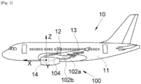
- FIG. 1 shows an aircraft 10 which comprises a fuselage 11 on each side of which is fixed a wing 13 which carries an engine 14 such as for example a dual-flow turbojet.
- the aircraft 10 also includes a mast 12 which ensures the attachment of the engine 14 under the wing 13.
- the aircraft 10 comprises a fire-fighting system 100 which comprises at least one tank 102a-b filled with an extinguishing fluid and, for each tank 102a-b, a discharge pipe 104 which extends between said tank 102a-b and the engine 14 supported by said mast 12.
- a fire-fighting system 100 which comprises at least one tank 102a-b filled with an extinguishing fluid and, for each tank 102a-b, a discharge pipe 104 which extends between said tank 102a-b and the engine 14 supported by said mast 12.
- a fire-fighting system 100 which comprises at least one tank 102a-b filled with an extinguishing fluid and, for each tank 102a-b, a discharge pipe 104 which extends between said tank 102a-b and the engine 14 supported by said mast 12.
- the reservoir 102a is equipped with a discharge head which is arranged to release the extinguishing fluid to the discharge line 104 when needed.
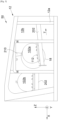
- THE Figs. 2 to 4 show a set 50 which includes the mast 12 and the tank 102a.
- the mast 12 conventionally extends in the longitudinal direction X and comprises a structure consisting of a frame 12a and walls fixed around the frame 12a.
- the frame 12a is made up, for example, of several profiles fixed to each other.
- the walls there are at least two side walls 12b which extend on either side of a vertical median plane XZ of the mast 12.
- the two side walls 12b are thus fixed on either side of the frame 12a in planes which are generally vertical and parallel to the median plane.
- Each side wall 12b is pierced by a window 18 (seen in the background on the Figs. 2 And 3 ) which allows access to the interior of the mast 12 and the chassis 12a from the exterior of the mast 12 and the window 18 is sized to allow the passage of the tank 102a.
- the two windows 18 are arranged opposite each other relative to the median plane XZ.
- the tank 102a is equipped with fixing means 112 which are arranged on either side of the median plane XZ when the tank 102a is in place. As explained below, when the tank 102a is placed in the mast 12 through the window 18, fixing means 112 are accessible from each window 18.
- the fixing means 112 are here tabs.
- the fixing means 112 cooperate with fixing elements to ensure the fixing of the tank 102a inside the mast 12 when the tank 102a is in place.
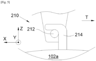
- the assembly 50 also comprises a hooking system 210 which is arranged to suspend the tank 102a inside the mast 12 opposite the windows 18.
- the suspension is releasable, that is to say that the tank 102a can be unhooked easily, or even automatically as described below.
- the hanging system 210 can be removable, that is to say dismountable and be removed after the installation of the tank 102a-b.
- the assembly 50 also includes a carriage 202 which is mounted inside the frame 12a and one embodiment of which is shown in Fig. 6 .
- a carriage 202 which is mounted inside the frame 12a and one embodiment of which is shown in Fig. 6 .
- a carriage 202 which is mounted inside the frame 12a and one embodiment of which is shown in Fig. 6 .
- the carriage 202 is mounted to move in translation parallel to a translation direction T relative to the chassis 12a.
- the assembly 50 comprises two rails 602 which are integral with the chassis 12a and along which the carriage 202 slides thanks to a sliding connection between the carriage 202 and the rails 602.
- the two rails 602 extend parallel to the translation direction T.
- the carriage 202 has a cradle 204 intended to receive the tank 102a and the carriage 202 is movable relative to the chassis 12a alternately between a positioning position ( Fig. 3 ) and a position of use ( Fig. 2 ).
- the carriage 202 In the position of installation, the carriage 202 is arranged so that the cradle 204 is opposite the windows 18 and under the tank 102a which is suspended from the attachment system 210 and in the position of use, the carriage 202 is arranged so that the cradle 204 is not opposite the windows 18.
- the carriage 202 moves in translation parallel to the translation direction T which is parallel to the median plane XZ and generally parallel to the longitudinal direction X.
- the translation direction T is slightly upwards towards the rear of the mast 12 relative to the longitudinal direction X.
- the carriage 202 therefore moves here towards the front of the mast 12 to reach the installation position or the rear of the mast 12 to reach the use position.
- the fixing means 112 are fixed to the cradle 204 using fixing elements such as screws which are screwed, through the legs, into the cradle 204 in bores 204a provided for this purpose.
- the assembly 50 also includes a locking system 700, one embodiment of which is shown in Fig. 7 and which alternately takes a locking position or a free position.
- a locking system 700 In the locking position, the locking system 700 blocks the carriage 202 in the use position and in the free position, the locking system 700 does not block the carriage 202 which is then free to move from the use position to the installation position and vice versa.
- THE Figs. 2 And 3 thus show a second tank 102b which is already placed in the use position and which is arranged towards the front of the mast 12.
- the transition from the use position to the installation position is thus reversed with respect to the first tank 102a.
- the translation directions of each tank 102a-b may be slightly different, but they remain generally parallel to the longitudinal direction X and therefore generally horizontal.
- the term generally is understood in the sense that the tank 102a-b moves alternately towards the front and rear of the mast 12.
- the assembly 50 comprises two tanks 102a-b
- the translation to move from the installation position to the use position is carried out in the opposite direction to the translation to move from the installation position to the use position of the other tank 102b-a.
- the cradle 204 has at least one first bearing face 206 facing upwards and each fixing means 112 has a second bearing face 208 facing downwards and when the reservoir 102a is in place on the cradle 204, each second bearing face 208 bears against a first bearing face 206.
- the cradle 204 has two first support faces 206 arranged on either side of the median plane XZ.
- the hanging system 210 comprises a bar 212 which is horizontal and perpendicular to the translation direction T, that is to say to the median plane XZ.
- the bar 212 is integral with the chassis 12a.
- the attachment system 210 may comprise a bar 212 per tank 102a-b depending on the position of the cradle 204 in the installation position.
- the hooking system 210 also comprises a hook 214 which is integral with the reservoir 102a and which here takes the form of an L which is arranged to hook onto the bar 212.
- the hook 214 is open on the side opposite the use position. Thus, when the reservoir 102a is moved from the installation position to the use position, it separates from the bar 212.
- the detachment of the tank 102a from the bar 212 is then automatic when the carriage 202 is moved to the position of use.
- the position of the bar 212 and the length of the hook 214 are provided so that, when the fixing means 112 are fixed to the cradle 204 by the fixing elements, the pressure exerted by the hook 214 on the bar 212 is sufficiently low to allow the movement of the carriage 202 and the movement of the hook 214 relative to the bar 212.
- the hanging system 210 may take another form.
- the hanging system may take the form of a bar similar to that described above and a clamp that grips the bar and is releasable by opening the clamp by a technician.
- each rail 602 is fixed at each of its ends to the frame 12a.
- a first end is fixed via a first fitting 604 of the chassis 12a and a second end is fixed via a second fitting 605 of the chassis 12a.
- the first end is integral with the associated fitting 604, i.e. on the chassis 12a, via an axis 606 and the second end is fixed to a lug 605a of the second fitting 605.
- the carriage 202 takes the form of a telescopic system which slides along the rails 602.
- the carriage 202 thus comprises two intermediate rails 608, where each is slidably mounted on one of the rails 602 by means of a sliding connection, and the cradle 204 also has two terminal rails 610 where each is slidably mounted on one of the intermediate rails 608 by means of a sliding connection.
- the locking system 700 comprises guiding and fixing elements on either side of the median plane XZ.
- Fig. 7 shows the guide and fixing elements which are on one side of the median plane XZ, and the guide and fixing elements which are on the other side are symmetrical.
- the locking system 700 thus comprises, on either side of the median plane XZ, a guide stud 702 secured to the frame 12a and oriented towards the position of installation and a housing 704 made in the cradle 204, here in a pallet 706 of said cradle 204.
- the guide stud 702 is integral with the second fitting 605.
- the housing 704 fits onto the stud 702 so as to fix the position of the cradle 204 relative to the chassis 12a.
- the housing 704 and the guide stud 702 are sized so that the fit between them is of the sliding or just sliding type.
- the locking system 700 thus comprises, on either side of the median plane XZ, a locking element 708 which secures the cradle 204 to the chassis 12a in the position of use.
- the locking element 708 takes the form of a screw which is screwed, through the housing 704, into a hole 710 made in the guide stud 702.
- each guide stud 702 takes the form of an oblong-shaped element with the major axis oriented vertically and each housing 704 takes the form of a corresponding oblong-shaped hole.
- the oblong shapes allow better alignment of the cradle 204 with respect to an optimal use position.
Landscapes
- Engineering & Computer Science (AREA)
- Chemical & Material Sciences (AREA)
- Combustion & Propulsion (AREA)
- Health & Medical Sciences (AREA)
- Public Health (AREA)
- Business, Economics & Management (AREA)
- Emergency Management (AREA)
- Aviation & Aerospace Engineering (AREA)
- Mechanical Engineering (AREA)
- General Engineering & Computer Science (AREA)
- Connection Of Plates (AREA)
Claims (8)
- Baugruppe (50) für ein Luftfahrzeug (10), wobei die Baugruppe (50) Folgendes aufweist:- einen Mast (12), der sich in einer Längsrichtung (X) erstreckt und einen Rahmen (12a) und zwei Seitenwände (12b) aufweist, die auf beiden Seiten des Rahmens (12a) angeordnet und jeweils von einem Fenster (18) durchbrochen sind,- mindestens einen Behälter (102a-b), der Befestigungsmittel (112) aufweist,- ein Aufhängungssystem (210), das dazu angeordnet ist, den oder jeden Behälter (102a-b) im Inneren des Masts (12) vor den Fenstern (18) aufzuhängen,dadurch gekennzeichnet, dass die Baugruppe Folgendes aufweist,für jeden Behälter (102a-b) einen Wagen (202), der eine Wiege (204) aufweist, die dazu bestimmt ist, den Behälter (102a-b) aufzunehmen, wobei der Wagen (202) im Inneren des Rahmens (12a) montiert ist, der in Bezug auf den Rahmen (12a) parallel zu einer Translationsrichtung (T), die zur Längsrichtung (X) im Allgemeinen parallel verläuft, zwischen einer Einsetzposition, in der der Wagen (202) so angeordnet ist, dass sich die Wiege (204) vor den Fenstern (18) und unter dem Behälter (102a-b) befindet, und einer Gebrauchsposition, in der der Wagen (202) so angeordnet ist, dass sich die Wiege (204) nicht vor den Fenstern (18) befindet, translatorisch hin- und herbewegbar ist,- für jeden Behälter (102a-b) Befestigungselemente, die die Befestigung der Befestigungsmittel (112) des Behälters (102a-b) an der Wiege (204) sicherstellen, und- für jeden Wagen (202) ein Verriegelungssystem (700), das abwechselnd eine Verriegelungsposition, in der das Verriegelungssystem (700) den Wagen (202) in der Gebrauchsposition blockiert, oder eine freie Position, in der das Verriegelungssystem (700) den Wagen (202) nicht blockiert, einnimmt.
- Baugruppe (50) nach Anspruch 1, dadurch gekennzeichnet, dass das Aufhängungssystem (210) Folgendes aufweist: eine horizontale Stange (212), die senkrecht zur Translationsrichtung (T) verläuft und fest mit dem Rahmen (12a) verbunden ist, und einen Haken (214), der fest mit dem Behälter (102a) verbunden ist, die Form eines L aufweist, dazu angeordnet ist, sich an der Stange (212) einzuhaken, und auf der der Gebrauchsposition gegenüberliegenden Seite offen ist.
- Baugruppe (50) nach einem der Ansprüche 1 oder 2, dadurch gekennzeichnet, dass sie zwei fest mit dem Rahmen (12a) verbundene Schienen (602) aufweist und dass der Wagen (202) über eine Gleitverbindung auf den Schienen (602) gleitend montiert ist.
- Baugruppe (50) nach Anspruch 3, dadurch gekennzeichnet, dass der Wagen (202) zwei Zwischenschienen (608) aufweist, wovon jede dank einer Gleitverbindung auf einer der Schienen (602) gleitend montiert ist, und dass die Wiege (204) zwei Endschienen (610) aufweist, wovon jede dank einer Gleitverbindung auf einer der Zwischenschienen (608) gleitend montiert ist.
- Baugruppe (50) nach einem der Ansprüche 1 bis 4, dadurch gekennzeichnet, dass das Verriegelungssystem (700) Folgendes aufweist: einen Führungsklotz (702) auf beiden Seiten einer Mittelebene (XZ), der fest mit dem Rahmen (12a) verbunden und in Richtung der Einsetzposition ausgerichtet ist, eine Aufnahme (704), die in der Wiege (204) ausgebildet ist, wobei die Aufnahme (704) in der Gebrauchsposition auf den Klotz (702) aufgesteckt ist, und ein Verriegelungselement (708), das in der Gebrauchsposition die Wiege (204) mit dem Rahmen (12a) verbindet.
- Baugruppe (50) nach Anspruch 5, dadurch gekennzeichnet, dass jeder Führungsklotz (702) die Form eines länglichen Elements aufweist, dessen Hauptachse vertikal ausgerichtet ist, und wobei jede Aufnahme (704) die Form eines länglichen Lochs aufweist.
- Baugruppe (50) nach einem der vorangehenden Ansprüche, dadurch gekennzeichnet, dass sie zwei Behälter (102a-b) aufweist und dass bei jedem der Behälter (102a-b) die Translation aus der Einsetzposition in die Gebrauchsposition in Gegenrichtung zur Translation aus der Einsetzposition in die Gebrauchsposition des anderen Behälters (102b-a) erfolgt.
- Luftfahrzeug (10) mit einer Baugruppe (50) nach einem der vorangehenden Ansprüche.
Applications Claiming Priority (1)
| Application Number | Priority Date | Filing Date | Title |
|---|---|---|---|
| FR2302163A FR3146461A1 (fr) | 2023-03-09 | 2023-03-09 | Ensemble pour un aéronef, ledit ensemble comportant un mat et un réservoir contenant un fluide extincteur |
Publications (2)
| Publication Number | Publication Date |
|---|---|
| EP4428039A1 EP4428039A1 (de) | 2024-09-11 |
| EP4428039B1 true EP4428039B1 (de) | 2025-04-16 |
Family
ID=86469031
Family Applications (1)
| Application Number | Title | Priority Date | Filing Date |
|---|---|---|---|
| EP24159746.7A Active EP4428039B1 (de) | 2023-03-09 | 2024-02-26 | Anordnung für ein flugzeug, besagte anordnung mit einer matte und einem tank mit löschflüssigkeit |
Country Status (4)
| Country | Link |
|---|---|
| US (1) | US12312096B2 (de) |
| EP (1) | EP4428039B1 (de) |
| CN (1) | CN118615618A (de) |
| FR (1) | FR3146461A1 (de) |
Families Citing this family (1)
| Publication number | Priority date | Publication date | Assignee | Title |
|---|---|---|---|---|
| FR3148009A1 (fr) * | 2023-04-21 | 2024-10-25 | Airbus Operations | Ensemble pour un aéronef, ledit ensemble comportant un mat et un réservoir contenant un agent extincteur |
Family Cites Families (10)
| Publication number | Priority date | Publication date | Assignee | Title |
|---|---|---|---|---|
| FR2942969B1 (fr) * | 2009-03-10 | 2011-03-04 | Airbus France | Dispositif d'extinction d'incendies pour aeronef et procede de fixation |
| US11439854B2 (en) * | 2017-08-17 | 2022-09-13 | The Boeing Company | Common array mounting bottles engineered for reuse |
| FR3094892B1 (fr) * | 2019-04-12 | 2022-07-01 | Airbus Operations Sas | Systeme anti-incendie pour un aeronef comportant un reservoir a double chambre |
| FR3099465B1 (fr) * | 2019-07-30 | 2022-12-02 | Airbus Operations Sas | Ensemble pour un aeronef, ledit ensemble comportant un mat et un reservoir contenant un fluide extincteur |
| FR3105177B1 (fr) * | 2019-12-18 | 2022-01-07 | Airbus Operations Sas | Ensemble pour un aeronef, ledit ensemble comportant un mat et un reservoir contenant un fluide extincteur |
| US20220250758A1 (en) * | 2021-02-05 | 2022-08-11 | General Electric Company | Remote mount of engine accessories |
| GB2604139A (en) * | 2021-02-25 | 2022-08-31 | Airbus Operations Ltd | Wingbox with removable fuel tank |
| FR3124793A1 (fr) * | 2021-07-02 | 2023-01-06 | Airbus Operations | Ensemble comportant une structure et un réservoir fixé à la structure et contenant un fluide extincteur |
| FR3148009A1 (fr) * | 2023-04-21 | 2024-10-25 | Airbus Operations | Ensemble pour un aéronef, ledit ensemble comportant un mat et un réservoir contenant un agent extincteur |
| EP4480827A1 (de) * | 2023-06-14 | 2024-12-25 | Airbus Operations (S.A.S.) | Flugzeugantriebsanordnung mit strahltriebwerk, pylon und löschsystem |
-
2023
- 2023-03-09 FR FR2302163A patent/FR3146461A1/fr not_active Ceased
-
2024
- 2024-02-26 EP EP24159746.7A patent/EP4428039B1/de active Active
- 2024-03-08 US US18/599,530 patent/US12312096B2/en active Active
- 2024-03-08 CN CN202410265989.2A patent/CN118615618A/zh active Pending
Also Published As
| Publication number | Publication date |
|---|---|
| FR3146461A1 (fr) | 2024-09-13 |
| EP4428039A1 (de) | 2024-09-11 |
| US20240300665A1 (en) | 2024-09-12 |
| US12312096B2 (en) | 2025-05-27 |
| CN118615618A (zh) | 2024-09-10 |
Similar Documents
| Publication | Publication Date | Title |
|---|---|---|
| EP2500268B1 (de) | Aufhängesäule eines Flugzeugmotors | |
| EP0674203B1 (de) | Vorrichtung zur Aufbewahrung eines holographischen Spiegels, besonders für Luftfahrzeuge | |
| EP4428039B1 (de) | Anordnung für ein flugzeug, besagte anordnung mit einer matte und einem tank mit löschflüssigkeit | |
| EP2139768B1 (de) | Flugzeugmotorbefestigungspylon mit einer mit einer tonnenmutter versehenen hinteren motorbefestigung | |
| FR3099465A1 (fr) | Ensemble pour un aeronef, ledit ensemble comportant un mat et un reservoir contenant un fluide extincteur | |
| FR2920138A1 (fr) | Dispositif d'accrochage de moteur d'aeronef comportant un dispositif de reprise des efforts de poussee a encombrement reduit | |
| FR2942969A1 (fr) | Dispositif d'extinction d'incendies pour aeronef et procede de fixation | |
| EP2160328A2 (de) | Sicherungsplatte und längliches griffelement für eine einteilige flugzeugantriebseinheit | |
| FR3105177A1 (fr) | Ensemble pour un aeronef, ledit ensemble comportant un mat et un reservoir contenant un fluide extincteur | |
| EP4296157B1 (de) | Flugzeug mit einem rumpf und einer durch einen rumpf lösbar befestigten platte mit befestigungsmitteln | |
| EP1538081A1 (de) | Aufhängung eines Triebwerks unter einer Flugzeugflügel | |
| FR3012114A1 (fr) | Ensemble propulsif d'aeronef comportant une nacelle pourvue d'un mecanisme de verrouillage et de fermeture des capots | |
| FR2905932A1 (fr) | Agencement pour attache de dispositif d'accrochage d'un moteur d'aeronef | |
| FR3057745A1 (fr) | Systeme coulissant et ensemble coulissant pour un tiroir, et ensemble de tiroir | |
| EP4450398B1 (de) | Anordnung für ein flugzeug, besagte anordnung mit einem mast und einem tank mit einem löschmittel | |
| FR3156756A1 (fr) | Ensemble propulsif pour aéronef comportant un moteur, un mât et des moyens d’accrochage du moteur au mât | |
| FR3121428A1 (fr) | Mât réacteur d’aéronef comportant un ensemble mobile de capots | |
| EP3303132B1 (de) | Mobiler klassenteiler für flugzeugkabine | |
| FR3129922A1 (fr) | Aéronef comportant un mât réacteur avec un ensemble mobile de capots et un système de verrouillage particulier | |
| FR3034741A1 (fr) | Dispositif de support d'un rail propre a guider un coulissement d'une porte laterale coulissante | |
| EP4389604B1 (de) | Flugzeug mit einem triebwerksmast mit einer beweglichen haube | |
| EP4428036A1 (de) | Flugzeugbordküchenmöbel mit einem wagenblockiersystem | |
| FR3139552A1 (fr) | Mât d’aéronef équipé d’un système de guidage pour le montage ou démontage d’un réservoir et procédé de montage/démontage dudit réservoir | |
| EP3809544B1 (de) | System zum verriegeln der bewegung einer halterung für elektrische komponenten in einem schaltschrank, insbesondere einem atex-zertifizierten schaltschrank, und schaltschrank, der mit einer solchen halterung ausgestattet ist | |
| FR3043647A1 (fr) | Aeronef muni d'une soute amovible |
Legal Events
| Date | Code | Title | Description |
|---|---|---|---|
| PUAI | Public reference made under article 153(3) epc to a published international application that has entered the european phase |
Free format text: ORIGINAL CODE: 0009012 |
|
| STAA | Information on the status of an ep patent application or granted ep patent |
Free format text: STATUS: REQUEST FOR EXAMINATION WAS MADE |
|
| 17P | Request for examination filed |
Effective date: 20240226 |
|
| AK | Designated contracting states |
Kind code of ref document: A1 Designated state(s): AL AT BE BG CH CY CZ DE DK EE ES FI FR GB GR HR HU IE IS IT LI LT LU LV MC ME MK MT NL NO PL PT RO RS SE SI SK SM TR |
|
| GRAP | Despatch of communication of intention to grant a patent |
Free format text: ORIGINAL CODE: EPIDOSNIGR1 |
|
| STAA | Information on the status of an ep patent application or granted ep patent |
Free format text: STATUS: GRANT OF PATENT IS INTENDED |
|
| RIC1 | Information provided on ipc code assigned before grant |
Ipc: F02C 7/20 20060101ALI20241014BHEP Ipc: A62C 35/02 20060101ALI20241014BHEP Ipc: F02C 7/25 20060101ALI20241014BHEP Ipc: B64D 45/00 20060101ALI20241014BHEP Ipc: A62C 35/08 20060101ALI20241014BHEP Ipc: A62C 3/08 20060101ALI20241014BHEP Ipc: B64D 29/02 20060101AFI20241014BHEP |
|
| INTG | Intention to grant announced |
Effective date: 20241028 |
|
| GRAS | Grant fee paid |
Free format text: ORIGINAL CODE: EPIDOSNIGR3 |
|
| GRAA | (expected) grant |
Free format text: ORIGINAL CODE: 0009210 |
|
| STAA | Information on the status of an ep patent application or granted ep patent |
Free format text: STATUS: THE PATENT HAS BEEN GRANTED |
|
| AK | Designated contracting states |
Kind code of ref document: B1 Designated state(s): AL AT BE BG CH CY CZ DE DK EE ES FI FR GB GR HR HU IE IS IT LI LT LU LV MC ME MK MT NL NO PL PT RO RS SE SI SK SM TR |
|
| REG | Reference to a national code |
Ref country code: GB Ref legal event code: FG4D Free format text: NOT ENGLISH |
|
| REG | Reference to a national code |
Ref country code: CH Ref legal event code: EP Ref country code: DE Ref legal event code: R096 Ref document number: 602024000063 Country of ref document: DE |
|
| REG | Reference to a national code |
Ref country code: IE Ref legal event code: FG4D Free format text: LANGUAGE OF EP DOCUMENT: FRENCH |
|
| REG | Reference to a national code |
Ref country code: NL Ref legal event code: MP Effective date: 20250416 |
|
| PG25 | Lapsed in a contracting state [announced via postgrant information from national office to epo] |
Ref country code: NL Free format text: LAPSE BECAUSE OF FAILURE TO SUBMIT A TRANSLATION OF THE DESCRIPTION OR TO PAY THE FEE WITHIN THE PRESCRIBED TIME-LIMIT Effective date: 20250416 |
|
| REG | Reference to a national code |
Ref country code: AT Ref legal event code: MK05 Ref document number: 1785484 Country of ref document: AT Kind code of ref document: T Effective date: 20250416 |
|
| PG25 | Lapsed in a contracting state [announced via postgrant information from national office to epo] |
Ref country code: FI Free format text: LAPSE BECAUSE OF FAILURE TO SUBMIT A TRANSLATION OF THE DESCRIPTION OR TO PAY THE FEE WITHIN THE PRESCRIBED TIME-LIMIT Effective date: 20250416 Ref country code: ES Free format text: LAPSE BECAUSE OF FAILURE TO SUBMIT A TRANSLATION OF THE DESCRIPTION OR TO PAY THE FEE WITHIN THE PRESCRIBED TIME-LIMIT Effective date: 20250416 Ref country code: PT Free format text: LAPSE BECAUSE OF FAILURE TO SUBMIT A TRANSLATION OF THE DESCRIPTION OR TO PAY THE FEE WITHIN THE PRESCRIBED TIME-LIMIT Effective date: 20250818 |
|
| REG | Reference to a national code |
Ref country code: LT Ref legal event code: MG9D |
|
| PG25 | Lapsed in a contracting state [announced via postgrant information from national office to epo] |
Ref country code: NO Free format text: LAPSE BECAUSE OF FAILURE TO SUBMIT A TRANSLATION OF THE DESCRIPTION OR TO PAY THE FEE WITHIN THE PRESCRIBED TIME-LIMIT Effective date: 20250716 Ref country code: GR Free format text: LAPSE BECAUSE OF FAILURE TO SUBMIT A TRANSLATION OF THE DESCRIPTION OR TO PAY THE FEE WITHIN THE PRESCRIBED TIME-LIMIT Effective date: 20250717 |
|
| PG25 | Lapsed in a contracting state [announced via postgrant information from national office to epo] |
Ref country code: PL Free format text: LAPSE BECAUSE OF FAILURE TO SUBMIT A TRANSLATION OF THE DESCRIPTION OR TO PAY THE FEE WITHIN THE PRESCRIBED TIME-LIMIT Effective date: 20250416 |
|
| PG25 | Lapsed in a contracting state [announced via postgrant information from national office to epo] |
Ref country code: BG Free format text: LAPSE BECAUSE OF FAILURE TO SUBMIT A TRANSLATION OF THE DESCRIPTION OR TO PAY THE FEE WITHIN THE PRESCRIBED TIME-LIMIT Effective date: 20250416 |
|
| PG25 | Lapsed in a contracting state [announced via postgrant information from national office to epo] |
Ref country code: HR Free format text: LAPSE BECAUSE OF FAILURE TO SUBMIT A TRANSLATION OF THE DESCRIPTION OR TO PAY THE FEE WITHIN THE PRESCRIBED TIME-LIMIT Effective date: 20250416 |
|
| PG25 | Lapsed in a contracting state [announced via postgrant information from national office to epo] |
Ref country code: AT Free format text: LAPSE BECAUSE OF FAILURE TO SUBMIT A TRANSLATION OF THE DESCRIPTION OR TO PAY THE FEE WITHIN THE PRESCRIBED TIME-LIMIT Effective date: 20250416 |
|
| PG25 | Lapsed in a contracting state [announced via postgrant information from national office to epo] |
Ref country code: RS Free format text: LAPSE BECAUSE OF FAILURE TO SUBMIT A TRANSLATION OF THE DESCRIPTION OR TO PAY THE FEE WITHIN THE PRESCRIBED TIME-LIMIT Effective date: 20250716 |
|
| PG25 | Lapsed in a contracting state [announced via postgrant information from national office to epo] |
Ref country code: IS Free format text: LAPSE BECAUSE OF FAILURE TO SUBMIT A TRANSLATION OF THE DESCRIPTION OR TO PAY THE FEE WITHIN THE PRESCRIBED TIME-LIMIT Effective date: 20250816 |
|
| PG25 | Lapsed in a contracting state [announced via postgrant information from national office to epo] |
Ref country code: LV Free format text: LAPSE BECAUSE OF FAILURE TO SUBMIT A TRANSLATION OF THE DESCRIPTION OR TO PAY THE FEE WITHIN THE PRESCRIBED TIME-LIMIT Effective date: 20250416 |
|
| PG25 | Lapsed in a contracting state [announced via postgrant information from national office to epo] |
Ref country code: SM Free format text: LAPSE BECAUSE OF FAILURE TO SUBMIT A TRANSLATION OF THE DESCRIPTION OR TO PAY THE FEE WITHIN THE PRESCRIBED TIME-LIMIT Effective date: 20250416 Ref country code: DK Free format text: LAPSE BECAUSE OF FAILURE TO SUBMIT A TRANSLATION OF THE DESCRIPTION OR TO PAY THE FEE WITHIN THE PRESCRIBED TIME-LIMIT Effective date: 20250416 |
|
| REG | Reference to a national code |
Ref country code: DE Ref legal event code: R097 Ref document number: 602024000063 Country of ref document: DE |
|
| PG25 | Lapsed in a contracting state [announced via postgrant information from national office to epo] |
Ref country code: CZ Free format text: LAPSE BECAUSE OF FAILURE TO SUBMIT A TRANSLATION OF THE DESCRIPTION OR TO PAY THE FEE WITHIN THE PRESCRIBED TIME-LIMIT Effective date: 20250416 |
|
| PG25 | Lapsed in a contracting state [announced via postgrant information from national office to epo] |
Ref country code: EE Free format text: LAPSE BECAUSE OF FAILURE TO SUBMIT A TRANSLATION OF THE DESCRIPTION OR TO PAY THE FEE WITHIN THE PRESCRIBED TIME-LIMIT Effective date: 20250416 |
|
| PG25 | Lapsed in a contracting state [announced via postgrant information from national office to epo] |
Ref country code: SK Free format text: LAPSE BECAUSE OF FAILURE TO SUBMIT A TRANSLATION OF THE DESCRIPTION OR TO PAY THE FEE WITHIN THE PRESCRIBED TIME-LIMIT Effective date: 20250416 |
|
| PG25 | Lapsed in a contracting state [announced via postgrant information from national office to epo] |
Ref country code: IT Free format text: LAPSE BECAUSE OF FAILURE TO SUBMIT A TRANSLATION OF THE DESCRIPTION OR TO PAY THE FEE WITHIN THE PRESCRIBED TIME-LIMIT Effective date: 20250416 |
|
| PLBE | No opposition filed within time limit |
Free format text: ORIGINAL CODE: 0009261 |
|
| STAA | Information on the status of an ep patent application or granted ep patent |
Free format text: STATUS: NO OPPOSITION FILED WITHIN TIME LIMIT |
|
| REG | Reference to a national code |
Ref country code: CH Ref legal event code: L10 Free format text: ST27 STATUS EVENT CODE: U-0-0-L10-L00 (AS PROVIDED BY THE NATIONAL OFFICE) Effective date: 20260225 |
|
| 26N | No opposition filed |
Effective date: 20260119 |