EP4310005B1 - Propellerantriebsanordnung für ein flugzeug - Google Patents
Propellerantriebsanordnung für ein flugzeug Download PDFInfo
- Publication number
- EP4310005B1 EP4310005B1 EP23186125.3A EP23186125A EP4310005B1 EP 4310005 B1 EP4310005 B1 EP 4310005B1 EP 23186125 A EP23186125 A EP 23186125A EP 4310005 B1 EP4310005 B1 EP 4310005B1
- Authority
- EP
- European Patent Office
- Prior art keywords
- propulsion unit
- chassis
- propulsion
- platform
- arches
- Prior art date
- Legal status (The legal status is an assumption and is not a legal conclusion. Google has not performed a legal analysis and makes no representation as to the accuracy of the status listed.)
- Active
Links
Images


Classifications
-
- B—PERFORMING OPERATIONS; TRANSPORTING
- B64—AIRCRAFT; AVIATION; COSMONAUTICS
- B64D—EQUIPMENT FOR FITTING IN OR TO AIRCRAFT; FLIGHT SUITS; PARACHUTES; ARRANGEMENT OR MOUNTING OF POWER PLANTS OR PROPULSION TRANSMISSIONS IN AIRCRAFT
- B64D27/00—Arrangement or mounting of power plants in aircraft; Aircraft characterised by the type or position of power plants
- B64D27/02—Aircraft characterised by the type or position of power plants
- B64D27/24—Aircraft characterised by the type or position of power plants using steam or spring force
-
- B—PERFORMING OPERATIONS; TRANSPORTING
- B64—AIRCRAFT; AVIATION; COSMONAUTICS
- B64C—AEROPLANES; HELICOPTERS
- B64C11/00—Propellers, e.g. of ducted type; Features common to propellers and rotors for rotorcraft
-
- B—PERFORMING OPERATIONS; TRANSPORTING
- B64—AIRCRAFT; AVIATION; COSMONAUTICS
- B64D—EQUIPMENT FOR FITTING IN OR TO AIRCRAFT; FLIGHT SUITS; PARACHUTES; ARRANGEMENT OR MOUNTING OF POWER PLANTS OR PROPULSION TRANSMISSIONS IN AIRCRAFT
- B64D27/00—Arrangement or mounting of power plants in aircraft; Aircraft characterised by the type or position of power plants
- B64D27/02—Aircraft characterised by the type or position of power plants
- B64D27/30—Aircraft characterised by electric power plants
- B64D27/34—All-electric aircraft
-
- B—PERFORMING OPERATIONS; TRANSPORTING
- B64—AIRCRAFT; AVIATION; COSMONAUTICS
- B64D—EQUIPMENT FOR FITTING IN OR TO AIRCRAFT; FLIGHT SUITS; PARACHUTES; ARRANGEMENT OR MOUNTING OF POWER PLANTS OR PROPULSION TRANSMISSIONS IN AIRCRAFT
- B64D27/00—Arrangement or mounting of power plants in aircraft; Aircraft characterised by the type or position of power plants
- B64D27/02—Aircraft characterised by the type or position of power plants
- B64D27/30—Aircraft characterised by electric power plants
- B64D27/35—Arrangements for on-board electric energy production, distribution, recovery or storage
- B64D27/355—Arrangements for on-board electric energy production, distribution, recovery or storage using fuel cells
-
- B—PERFORMING OPERATIONS; TRANSPORTING
- B64—AIRCRAFT; AVIATION; COSMONAUTICS
- B64D—EQUIPMENT FOR FITTING IN OR TO AIRCRAFT; FLIGHT SUITS; PARACHUTES; ARRANGEMENT OR MOUNTING OF POWER PLANTS OR PROPULSION TRANSMISSIONS IN AIRCRAFT
- B64D29/00—Power-plant nacelles, fairings or cowlings
- B64D29/02—Power-plant nacelles, fairings or cowlings associated with wings
-
- H—ELECTRICITY
- H01—ELECTRIC ELEMENTS
- H01M—PROCESSES OR MEANS, e.g. BATTERIES, FOR THE DIRECT CONVERSION OF CHEMICAL ENERGY INTO ELECTRICAL ENERGY
- H01M8/00—Fuel cells; Manufacture thereof
- H01M8/24—Grouping of fuel cells, e.g. stacking of fuel cells
- H01M8/2465—Details of groupings of fuel cells
-
- B—PERFORMING OPERATIONS; TRANSPORTING
- B64—AIRCRAFT; AVIATION; COSMONAUTICS
- B64D—EQUIPMENT FOR FITTING IN OR TO AIRCRAFT; FLIGHT SUITS; PARACHUTES; ARRANGEMENT OR MOUNTING OF POWER PLANTS OR PROPULSION TRANSMISSIONS IN AIRCRAFT
- B64D41/00—Power installations for auxiliary purposes
- B64D2041/005—Fuel cells
-
- B—PERFORMING OPERATIONS; TRANSPORTING
- B64—AIRCRAFT; AVIATION; COSMONAUTICS
- B64D—EQUIPMENT FOR FITTING IN OR TO AIRCRAFT; FLIGHT SUITS; PARACHUTES; ARRANGEMENT OR MOUNTING OF POWER PLANTS OR PROPULSION TRANSMISSIONS IN AIRCRAFT
- B64D27/00—Arrangement or mounting of power plants in aircraft; Aircraft characterised by the type or position of power plants
- B64D27/40—Arrangements for mounting power plants in aircraft
- B64D27/402—Arrangements for mounting power plants in aircraft comprising box like supporting frames, e.g. pylons or arrangements for embracing the power plant
-
- H—ELECTRICITY
- H01—ELECTRIC ELEMENTS
- H01M—PROCESSES OR MEANS, e.g. BATTERIES, FOR THE DIRECT CONVERSION OF CHEMICAL ENERGY INTO ELECTRICAL ENERGY
- H01M2250/00—Fuel cells for particular applications; Specific features of fuel cell system
- H01M2250/20—Fuel cells in motive systems, e.g. vehicle, ship, plane
-
- Y—GENERAL TAGGING OF NEW TECHNOLOGICAL DEVELOPMENTS; GENERAL TAGGING OF CROSS-SECTIONAL TECHNOLOGIES SPANNING OVER SEVERAL SECTIONS OF THE IPC; TECHNICAL SUBJECTS COVERED BY FORMER USPC CROSS-REFERENCE ART COLLECTIONS [XRACs] AND DIGESTS
- Y02—TECHNOLOGIES OR APPLICATIONS FOR MITIGATION OR ADAPTATION AGAINST CLIMATE CHANGE
- Y02T—CLIMATE CHANGE MITIGATION TECHNOLOGIES RELATED TO TRANSPORTATION
- Y02T90/00—Enabling technologies or technologies with a potential or indirect contribution to GHG emissions mitigation
- Y02T90/40—Application of hydrogen technology to transportation, e.g. using fuel cells
Definitions
- the present invention relates to a propeller propulsion unit for an aircraft, said propulsion unit comprising a chassis fixed to a structure of a wing of the aircraft and a propulsion system consisting of at least one tray carrying at least one piece of equipment where the chassis has an opening in the lower part and where the tray is fixed to the chassis through said opening.
- the invention also relates to an aircraft comprising at least one such propulsion unit.
- an aircraft typically comprises at least one propulsion unit comprising a propulsion system arranged in a nacelle.
- the propulsion system comprises a chassis, an engine attached to the chassis and a propeller driven in rotation by the engine.
- the chassis of the nacelle is attached under a mast which is itself attached under a structure of the aircraft's wing.
- the propulsion system and more specifically the engine, has many elements that are attached either to the mast or to the chassis and these elements are generally nested in a complex manner inside the chassis.
- disassembly of the elements can be complex because the elements to be checked may be fixed behind other elements which must be disassembled before accessing the elements to be checked.
- An object of the present invention is to provide a propulsion assembly which allows easy disassembly and reassembly of the elements constituting the propulsion system.
- the fixing means takes the form of a stirrup with two legs, each pierced with a bore and secured to the plate, a tab secured to the chassis and which has a spherical bore in which is housed a sphere itself crossed by a bore, and a bolt whose threaded rod passes through each bore.
- the fixing means takes the form of a connecting rod with three fixing points where each fixing point allows rotation around an axis parallel to a transverse direction of the propulsion assembly where the connecting rod is fixed by two fixing points to the plate and by one fixing point to the chassis.
- said propulsion unit comprises a nacelle made up of covers and the fixing means also ensure the fixing of the covers to the chassis.
- said propulsion assembly comprises additional fixing means which directly fix the covers to the plate.
- the invention also proposes an aircraft comprising at least one propulsion unit according to one of the preceding variants.
- X is the longitudinal direction which corresponds to the axis of the aircraft oriented positively forward in the direction of advancement of the aircraft
- Y is the transverse direction which is horizontal when the aircraft is on the ground
- Z is the vertical direction or vertical height when the aircraft is on the ground, these three directions X, Y and Z being orthogonal to each other.
- FIG. 1 shows an aircraft 100 which has a fuselage 102 on either side of which a wing 104 is fixed. Under each wing 104 is fixed at least one propulsion unit 151 which comprises a nacelle 149 made up of cowls 147 forming an aerodynamic exterior surface.
- Fig. 2 shows the propulsion assembly 151 without the nacelle 149 and which also comprises a propulsion system 150 which is in exploded view.
- the propulsion assembly 151 has a longitudinal direction parallel to the longitudinal direction X of the aircraft 100, a transverse direction parallel to the transverse direction Y of the aircraft 100 and a vertical direction parallel to the vertical direction Z of the aircraft 100.
- the propulsion system 150 comprises an electric motor 154a and a propeller 152 mounted on the shaft of the electric motor 154a and therefore driven in rotation by said electric motor 154a.
- the axis of rotation of the propeller 152 is generally parallel to the longitudinal direction X.
- the propulsion assembly 151 also comprises a chassis 156 extending parallel to the longitudinal direction X and comprising structural elements connected together to form a cage.
- the chassis 156 constitutes a mast fixed to a structure of the wing 104 by fixing points 157a-d arranged in the upper part of the chassis 156 and which are here four in number.
- There is a rear fixing point 157a which is arranged at the rear of the chassis 156 and compensates for the Z forces.
- There is a front fixing point 157b which is in front of the rear fixing point 157a and which compensates for the Y forces.
- the structural elements of the chassis 156 comprise a plurality of arches 158, here five, arranged one after the other along the longitudinal direction X and between two successive arches 158, beams 160a-b fixed by their ends to the two successive arches 158.
- Each arch 158 is open downwards.
- the two lower port ends of the two arches 158 are connected by a lower beam 160b and the two lower starboard ends of the two arches 158 are connected by another lower beam 160b.
- beams 160a which connect the arches 158 together, above the lower beams 160b, so as to form a confined and hollow space inside the frame 156.
- the lower beams 160b and the arches 158 delimit an opening 162 which is open downwards.
- the propulsion system 150 also comprises a fuel cell 154b, a tank 154c containing dihydrogen, and a cooling system 154d.
- the propulsion system 150 may comprise other elements such as, for example, air supply systems, ...
- the propulsion assembly 151 also comprises at least one plate 180 and on said or each plate is fixed at least one propulsion element 154a-d of the propulsion system 150 by any suitable means such as screw elements, welds, etc.
- FIG. 6 shows a second embodiment in which the tray 180 is fixed to the chassis 156 by two fixing means 182 at the front (one on the port side and one on the starboard side) and by two fixing means 682 at the rear (one on the port side and one on the starboard side).
- the fixing means 182 at the front may be rigid or flexible like those described in Figs. 4 and 5 and ensure a recovery of efforts in X, Y and Z.
- Each attachment means 682 at the rear takes the form of a connecting rod with three attachment points where each attachment point allows rotation around an axis parallel to the transverse direction of the propulsion unit 151, i.e. horizontal and perpendicular to the longitudinal direction.
- the connecting rod is attached by two attachment points to the plate 180 and by one attachment point to the chassis 156 here at the level of a beam 160a.
- Each attachment means 682 ensures a take-up of the forces in X and Z. Of course, a reverse assembly is possible with two attachment points to the chassis 156 and one attachment point to the plate 180.
- FIG. 7 shows a third embodiment in which the tray 180 is fixed to the chassis 156 by two pairs of fixing means 182, one pair at the front and one pair at the rear and for each pair, one fixing means 182 on the port side and one on the starboard side.
- the fixing is completed by two fixing means 782 (one on the port side and one on the starboard side) between the pair at the front and the pair at the rear.
- the fixing means 182 at the front and rear may be rigid or flexible like those described in Figs. 4 and 5 and ensure a recovery of efforts in X, Y and Z.
- Each intermediate fixing means 782 takes the form of a connecting rod with three fixing points where each fixing point allows rotation around an axis parallel to the transverse direction of the propulsion assembly 151, that is to say horizontal and perpendicular to the longitudinal direction.
- the connecting rod is fixed by two fixing points to the plate 180 and by one fixing point to the chassis 156 here at the level of a beam 160a.
- Each fixing means 782 ensures a recovery of the forces in X and Z. Of course, a reverse assembly is possible with two fixing points to the chassis 156 and one fixing point to the plate 180.
- FIG. 8 shows a fourth embodiment in which the tray 180 is fixed to the chassis 156 by two fixing means 182 at the front (one on the port side and one on the starboard side) and by a fixing means 882 at the rear.
- the fixing means 182 at the front may be rigid or flexible like those described in Figs. 4 and 5 and ensure a recovery of efforts in X, Y and Z.
- the fixing means 882 at the rear takes the form of a connecting rod with three fixing points where each fixing point allows rotation around an axis parallel to the longitudinal direction of the propulsion unit 151.
- the connecting rod is fixed by two fixing points to the plate 180 and by one fixing point to the chassis 156.
- the fixing means 882 ensures a take-up of the forces in Y and Z.
- a reverse assembly is possible with two fixing points to the chassis 156 and one fixing point to the plate 180.
- the platform 180 is fixed to the chassis 156 represented here by the arches 158 by fixing means 182 which here take the form of rivets or screw elements such as a screw/nut system and which simultaneously fix the platform 180 and the covers 147 of the nacelle 149 to the chassis 156.
- the tray 180 is thus housed inside the chassis 156 and the covers 147 are outside the chassis 156.
- the platform 180 and the covers 147 of the nacelle 149 are fixed to the chassis 156 represented here by the arches 158 by fixing means 182 which here take the form of rivets or screw elements such as a screw/nut system and which simultaneously fix the platform 180 and the covers 147 of the nacelle 149 to the chassis 156.
- the propulsion assembly 151 also comprises additional fixing means 1082 which directly fix the covers 147 to the platform 180 and which also here take the form of rivets or screw elements such as a screw/nut system.
- each 180 tray is made up of several sub-trays independent of each other for the Figs. 11 and 12 and connected to each other for the Fig. 13 .
- Each sub-tray is fixed to the chassis 156 by fixing means 182.
- the fixing means 182 shown are arranged in pairs with one fixing means 182 on the port side and one on the starboard side of each sub-tray, thus repeating the fixing means 482, 582 described in Figs. 4 and 5 , but each means of attachment may have a different location and have a different shape and take other forms such as those described in Figs. 6 to 10 .
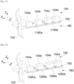
- the plate 180 consists of two sub-plates 1180a-b separated from each other and arranged one behind the other in the longitudinal direction. On each sub-plate 1180a-b is fixed at least one propulsion element 154a-d of the propulsion system 150.
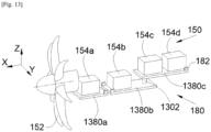
- the plate 180 consists of four sub-plates 1280a-d separated from each other and arranged one behind the other in the longitudinal direction. On each sub-plate 1280a-d is fixed at least one propulsion element 154a-d of the propulsion system 150.
Landscapes
- Engineering & Computer Science (AREA)
- Aviation & Aerospace Engineering (AREA)
- Life Sciences & Earth Sciences (AREA)
- Manufacturing & Machinery (AREA)
- Sustainable Development (AREA)
- Sustainable Energy (AREA)
- Chemical & Material Sciences (AREA)
- Chemical Kinetics & Catalysis (AREA)
- Electrochemistry (AREA)
- General Chemical & Material Sciences (AREA)
- Transmission Devices (AREA)
- Arrangement Or Mounting Of Propulsion Units For Vehicles (AREA)
Claims (11)
- Antriebsanordnung (151) für ein Flugzeug (100), umfassend:- einen hohlen Rahmen (156), der im unteren Teil eine Öffnung (162) aufweist,- ein Antriebssystem (150), das die folgenden Antriebselemente umfasst: einen Elektromotor (154a), auf dessen Motorwelle ein Propeller (152) montiert ist, eine Brennstoffzelle (154b), die den Elektromotor (154a) mit Strom versorgt, einen Tank (154c), der die Brennstoffzelle (154b) mit Wasserstoff versorgt, und ein Kühlsystem (154d), wobei die Antriebsanordnung dadurch gekennzeichnet ist, dass sie ferner mindestens eine Platte (180) umfasst, wobei die oder jede Platte (180) durch Befestigungsmittel (182) an dem Rahmen (156) befestigt ist und die Öffnung (162) verschließt und wobei auf der oder jeder Platte (180) mindestens ein Antriebselement (154a-d) des Antriebssystems (150) befestigt ist.
- Antriebsanordnung (151) nach Anspruch 1, dadurch gekennzeichnet, dass der Rahmen (156) eine Vielzahl von Bögen (158), die einer hinter dem anderen angeordnet sind, und zwischen zwei aufeinanderfolgenden Bögen (158) Träger (160a-b), die mit ihren Enden an den zwei aufeinanderfolgenden Bögen (158) befestigt sind, umfasst, wobei jeder Bogen (158) nach unten hin offen ist und wobei für zwei aufeinanderfolgende Bögen (158) die zwei backbordseitigen unteren Enden der zwei Bögen (158) durch einen unteren Träger (160b) verbunden sind und die zwei steuerbordseitigen unteren Enden der zwei Bögen (158) durch einen weiteren unteren Träger (160b) verbunden sind.
- Antriebsanordnung (151) nach einem der Ansprüche 1 oder 2, dadurch gekennzeichnet, dass das Befestigungsmittel (482) die Form eines Bügels (402) mit zwei Laschen, von denen jede von einer Bohrung durchbohrt ist und fest mit der Platte (180) verbunden ist, einer Zunge (404), die fest mit dem Rahmen (156) verbunden ist und eine kreisförmige Bohrung aufweist, in der eine Kugel aufgenommen ist, die ihrerseits von einer Bohrung durchquert wird, und eines Bolzens (406), dessen Gewindeschaft jede Bohrung durchquert, annimmt.
- Antriebsanordnung (151) nach einem der Ansprüche 1 oder 2, dadurch gekennzeichnet, dass das Befestigungsmittel (582) die Form einer ersten Zunge (502), die von einer Bohrung durchbohrt ist und fest mit der Platte (180) verbunden ist, einer zweiten Zunge (504), die von einer Bohrung durchbohrt ist und fest mit dem Rahmen (156) verbunden ist, eines Blocks (506), der aus einem flexiblen Material besteht, zweier Gewindeschafte, die fest mit dem Block (506) verbunden sind und auf beiden Seiten des Blocks (506) koaxial zueinander eingerichtet sind, und, für jeden Gewindeschaft, einer Mutter, die gegen die entsprechende Zunge (502, 504) gespannt wird, annimmt.
- Antriebsanordnung (151) nach einem der Ansprüche 1 oder 2, dadurch gekennzeichnet, dass das Befestigungsmittel (682, 782) die Form einer Stange mit drei Befestigungspunkten annimmt, wobei jeder Befestigungspunkt eine Drehung um eine zu einer Querrichtung der Antriebsanordnung (151) parallelen Achse gestattet, wobei die Stange mit zwei Befestigungspunkten an der Platte (180) und mit einem Befestigungspunkt an dem Rahmen (156) befestigt ist.
- Antriebsanordnung (151) nach einem der Ansprüche 1 oder 2, dadurch gekennzeichnet, dass das Befestigungsmittel (882) die Form einer Stange mit drei Befestigungspunkten annimmt, wobei jeder Befestigungspunkt eine Drehung um eine zu einer Längsrichtung der Antriebsanordnung (151) parallelen Achse gestattet, wobei die Stange mit zwei Befestigungspunkten an der Platte (180) und mit einem Befestigungspunkt an dem Rahmen (156) befestigt ist.
- Antriebsanordnung (151) nach einem der Ansprüche 1 bis 6, dadurch gekennzeichnet, dass die Antriebsanordnung (151) eine Gondel (149) umfasst, die aus Hauben (147) besteht, und dass die Befestigungsmittel (182) auch die Befestigung der Hauben (147) an dem Rahmen (156) gewährleisten.
- Antriebsanordnung (151) nach Anspruch 7, dadurch gekennzeichnet, dass die Antriebsanordnung (151) zusätzliche Befestigungsmittel (1082) umfasst, die die Hauben (147) direkt an der Platte (180) befestigen.
- Antriebsanordnung (151) nach einem der Ansprüche 1 bis 8, dadurch gekennzeichnet, dass die Platte (180) aus mehreren Teilplatten besteht, die entlang einer Längsrichtung der Antriebsanordnung (151) hintereinander angeordnet sind, und wobei jede Teilplatte mit Hilfe von Befestigungsmitteln (182) an dem Rahmen (156) befestigt ist.
- Antriebsanordnung (151) nach Anspruch 9, dadurch gekennzeichnet, dass der Elektromotor (154a) mit dem Propeller (152) von der vordersten Teilplatte getragen wird.
- Flugzeug (100), das mindestens eine Antriebsanordnung (151) nach einem der vorhergehenden Ansprüche umfasst.
Applications Claiming Priority (1)
| Application Number | Priority Date | Filing Date | Title |
|---|---|---|---|
| FR2207562A FR3138117A1 (fr) | 2022-07-22 | 2022-07-22 | Ensemble propulsif à hélice pour aéronef |
Publications (2)
| Publication Number | Publication Date |
|---|---|
| EP4310005A1 EP4310005A1 (de) | 2024-01-24 |
| EP4310005B1 true EP4310005B1 (de) | 2025-04-09 |
Family
ID=83439164
Family Applications (1)
| Application Number | Title | Priority Date | Filing Date |
|---|---|---|---|
| EP23186125.3A Active EP4310005B1 (de) | 2022-07-22 | 2023-07-18 | Propellerantriebsanordnung für ein flugzeug |
Country Status (4)
| Country | Link |
|---|---|
| US (1) | US12214890B2 (de) |
| EP (1) | EP4310005B1 (de) |
| CN (1) | CN117446184A (de) |
| FR (1) | FR3138117A1 (de) |
Families Citing this family (1)
| Publication number | Priority date | Publication date | Assignee | Title |
|---|---|---|---|---|
| WO2025184696A1 (en) * | 2024-03-06 | 2025-09-12 | AMSL Innovations Pty Ltd | Aircraft and electric power systems for aircraft |
Family Cites Families (12)
| Publication number | Priority date | Publication date | Assignee | Title |
|---|---|---|---|---|
| US6131848A (en) * | 1997-10-02 | 2000-10-17 | Crow; Steven Collins | Roadable airplane drive through an automotive transaxle |
| US7318565B2 (en) * | 2005-12-16 | 2008-01-15 | Itt Manufacturing Enterprises, Inc. | Electric motor assisted takeoff device for an air vehicle |
| US7845159B2 (en) * | 2006-08-31 | 2010-12-07 | General Electric Company | Heat pipe-based cooling apparatus and method for turbine engine |
| DE102014107316A1 (de) * | 2014-05-23 | 2015-11-26 | Airbus Operations Gmbh | Tanksystem zur kryogenen Lagerung von Wasserstoff und Flugzeug mit einem Tanksystem zur kryogenen Lagerung von Wasserstoff |
| CN108349592B (zh) * | 2015-09-04 | 2021-11-26 | 洛德公司 | 用于涡轮螺旋桨发动机/涡轮轴发动机的反扭矩后机架系统、装置和方法 |
| US10197128B2 (en) * | 2017-02-03 | 2019-02-05 | Hutchinson Aerospace & Industry Inc. | Hydraulic torque compensation device |
| FR3096348B1 (fr) * | 2019-05-21 | 2021-10-15 | Airbus Operations Sas | Systeme d’attache moteur avant pour un moteur d’aeronef comportant des systemes de bielles a deux bielles |
| FR3097202B1 (fr) * | 2019-06-14 | 2024-02-23 | Airbus | Systeme autonome de propulsion a helice pour un aeronef, ledit systeme autonome de propulsion a helice comportant une pile a combustible |
| WO2022157245A1 (en) * | 2021-01-22 | 2022-07-28 | Blue Spirit Aero Sas | Aircraft propulsion module and aircraft |
| FR3123050A1 (fr) * | 2021-05-20 | 2022-11-25 | Airbus Sas | Système de réservoir comportant un châssis, un réservoir de dihydrogène et des moyens de fixation du réservoir au châssis |
| EP4299445A1 (de) * | 2022-06-27 | 2024-01-03 | Airbus Operations (S.A.S.) | Elektrische antriebsanordnung mit mindestens zwei unabhängigen trägern, luftfahrzeug mit mindestens einer solchen elektrischen antriebsanordnung |
| FR3137367A1 (fr) * | 2022-07-04 | 2024-01-05 | Airbus Operations (S.A.S.) | Structure en treillis renforcée et aéronef comprenant au moins une telle structure |
-
2022
- 2022-07-22 FR FR2207562A patent/FR3138117A1/fr not_active Ceased
-
2023
- 2023-07-18 EP EP23186125.3A patent/EP4310005B1/de active Active
- 2023-07-20 US US18/355,779 patent/US12214890B2/en active Active
- 2023-07-21 CN CN202310908958.XA patent/CN117446184A/zh active Pending
Also Published As
| Publication number | Publication date |
|---|---|
| CN117446184A (zh) | 2024-01-26 |
| US20240025553A1 (en) | 2024-01-25 |
| FR3138117A1 (fr) | 2024-01-26 |
| EP4310005A1 (de) | 2024-01-24 |
| US12214890B2 (en) | 2025-02-04 |
Similar Documents
| Publication | Publication Date | Title |
|---|---|---|
| EP2723642B1 (de) | Aufhängestruktur einer turbomaschine | |
| EP1614625B1 (de) | Flugzeugdeck | |
| CA2576100C (fr) | Mat d'accrochage de turboreacteur pour aeronef | |
| EP2500268A1 (de) | Aufhängesäule eines Flugzeugmotors | |
| EP1535838A1 (de) | Aufhängung eines Triebwerks unter einer Flugzeugtragfläche | |
| FR3059298A1 (fr) | Ensemble pour aeronef comprenant un moteur de type " open rotor puller " et des moyens d'accrochage de celui-ci a la structure rigide d'un mat d'accrochage | |
| EP1614622B1 (de) | Flugzeugcockpitboden | |
| WO2008125631A1 (fr) | Dispositif d'accrochage de moteur d'aeronef et aeronef comportant au moins un tel dispositif | |
| CA2575982C (fr) | Ensemble moteur pour aeronef | |
| EP4310005B1 (de) | Propellerantriebsanordnung für ein flugzeug | |
| EP1535837A1 (de) | Vorrichtung für die Aufhängung eines Triebwerks an einem Flugzeugflügel | |
| CA2486496C (fr) | Dispositif d'accrochage d'un moteur sous une voilure d'aeronef | |
| WO2006021721A1 (fr) | Ensemble moteur pour aeronef | |
| EP4484297B1 (de) | Vordermotorbefestigungssystem für einen flugzeugmotor mit kompakter struktur | |
| EP3521173A1 (de) | Einheit für luftfahrzeug, die eine primärstruktur einer aufhängesäule umfasst, die an einem fahrwerkskasten mithilfe einer verschraubten verbindung befestigt ist | |
| FR3156756A1 (fr) | Ensemble propulsif pour aéronef comportant un moteur, un mât et des moyens d’accrochage du moteur au mât | |
| EP0619793B1 (de) | Flugzeug mit mindestens zwei triebwerken fü jede tragfläche | |
| FR3125798A1 (fr) | Ensemble propulsif pour aéronef comportant un turboréacteur, un mât et des moyens d’accrochage du turboréacteur au mât | |
| FR3147251A1 (fr) | Ensemble propulsif pour aéronef comportant un turboréacteur, un mât et des moyens d’accrochage du turboréacteur au mât | |
| EP4378833A1 (de) | Propellerantriebsanordnung für ein flugzeug | |
| EP4112477B1 (de) | Flugzeug-propellerbaugruppe, die eine vordere motorbefestigung umfasst, die einen querträger umfasst, der teilweise mit einer vorderen querverstärkung einer primärstruktur eines masts positioniert ist | |
| EP4488178B1 (de) | Montage eines befestigungsmastes mit einem flugzeugmotor | |
| FR3131734A1 (fr) | Ensemble propulsif pour aéronef comportant un turboréacteur, un mât et des moyens d’accrochage du turboréacteur au mât | |
| EP4442577B1 (de) | Reaktormast zur befestigung eines flugzeugmotors | |
| FR3152496A1 (fr) | Aéronef comportant au moins un système d’attache moteur présentant des attaches voilures positionnées approximativement dans un plan longitudinal médian |
Legal Events
| Date | Code | Title | Description |
|---|---|---|---|
| PUAI | Public reference made under article 153(3) epc to a published international application that has entered the european phase |
Free format text: ORIGINAL CODE: 0009012 |
|
| STAA | Information on the status of an ep patent application or granted ep patent |
Free format text: STATUS: THE APPLICATION HAS BEEN PUBLISHED |
|
| AK | Designated contracting states |
Kind code of ref document: A1 Designated state(s): AL AT BE BG CH CY CZ DE DK EE ES FI FR GB GR HR HU IE IS IT LI LT LU LV MC ME MK MT NL NO PL PT RO RS SE SI SK SM TR |
|
| STAA | Information on the status of an ep patent application or granted ep patent |
Free format text: STATUS: REQUEST FOR EXAMINATION WAS MADE |
|
| 17P | Request for examination filed |
Effective date: 20240723 |
|
| RBV | Designated contracting states (corrected) |
Designated state(s): AL AT BE BG CH CY CZ DE DK EE ES FI FR GB GR HR HU IE IS IT LI LT LU LV MC ME MK MT NL NO PL PT RO RS SE SI SK SM TR |
|
| REG | Reference to a national code |
Ref country code: DE Ref legal event code: R079 Free format text: PREVIOUS MAIN CLASS: B64D0027240000 Ipc: B64D0027400000 Ref document number: 602023002809 Country of ref document: DE |
|
| GRAP | Despatch of communication of intention to grant a patent |
Free format text: ORIGINAL CODE: EPIDOSNIGR1 |
|
| STAA | Information on the status of an ep patent application or granted ep patent |
Free format text: STATUS: GRANT OF PATENT IS INTENDED |
|
| RIC1 | Information provided on ipc code assigned before grant |
Ipc: B64D 27/34 20240101ALI20241009BHEP Ipc: B64D 27/355 20240101ALI20241009BHEP Ipc: B64D 27/40 20240101AFI20241009BHEP |
|
| INTG | Intention to grant announced |
Effective date: 20241106 |
|
| GRAS | Grant fee paid |
Free format text: ORIGINAL CODE: EPIDOSNIGR3 |
|
| GRAA | (expected) grant |
Free format text: ORIGINAL CODE: 0009210 |
|
| STAA | Information on the status of an ep patent application or granted ep patent |
Free format text: STATUS: THE PATENT HAS BEEN GRANTED |
|
| AK | Designated contracting states |
Kind code of ref document: B1 Designated state(s): AL AT BE BG CH CY CZ DE DK EE ES FI FR GB GR HR HU IE IS IT LI LT LU LV MC ME MK MT NL NO PL PT RO RS SE SI SK SM TR |
|
| REG | Reference to a national code |
Ref country code: GB Ref legal event code: FG4D Free format text: NOT ENGLISH |
|
| REG | Reference to a national code |
Ref country code: CH Ref legal event code: EP |
|
| REG | Reference to a national code |
Ref country code: DE Ref legal event code: R096 Ref document number: 602023002809 Country of ref document: DE |
|
| REG | Reference to a national code |
Ref country code: IE Ref legal event code: FG4D Free format text: LANGUAGE OF EP DOCUMENT: FRENCH |
|
| REG | Reference to a national code |
Ref country code: NL Ref legal event code: MP Effective date: 20250409 |
|
| PG25 | Lapsed in a contracting state [announced via postgrant information from national office to epo] |
Ref country code: NL Free format text: LAPSE BECAUSE OF FAILURE TO SUBMIT A TRANSLATION OF THE DESCRIPTION OR TO PAY THE FEE WITHIN THE PRESCRIBED TIME-LIMIT Effective date: 20250409 |
|
| REG | Reference to a national code |
Ref country code: AT Ref legal event code: MK05 Ref document number: 1783351 Country of ref document: AT Kind code of ref document: T Effective date: 20250409 |
|
| PG25 | Lapsed in a contracting state [announced via postgrant information from national office to epo] |
Ref country code: FI Free format text: LAPSE BECAUSE OF FAILURE TO SUBMIT A TRANSLATION OF THE DESCRIPTION OR TO PAY THE FEE WITHIN THE PRESCRIBED TIME-LIMIT Effective date: 20250409 Ref country code: PT Free format text: LAPSE BECAUSE OF FAILURE TO SUBMIT A TRANSLATION OF THE DESCRIPTION OR TO PAY THE FEE WITHIN THE PRESCRIBED TIME-LIMIT Effective date: 20250811 Ref country code: ES Free format text: LAPSE BECAUSE OF FAILURE TO SUBMIT A TRANSLATION OF THE DESCRIPTION OR TO PAY THE FEE WITHIN THE PRESCRIBED TIME-LIMIT Effective date: 20250409 |
|
| PGFP | Annual fee paid to national office [announced via postgrant information from national office to epo] |
Ref country code: DE Payment date: 20250722 Year of fee payment: 3 |
|
| REG | Reference to a national code |
Ref country code: LT Ref legal event code: MG9D |
|
| PG25 | Lapsed in a contracting state [announced via postgrant information from national office to epo] |
Ref country code: NO Free format text: LAPSE BECAUSE OF FAILURE TO SUBMIT A TRANSLATION OF THE DESCRIPTION OR TO PAY THE FEE WITHIN THE PRESCRIBED TIME-LIMIT Effective date: 20250709 Ref country code: GR Free format text: LAPSE BECAUSE OF FAILURE TO SUBMIT A TRANSLATION OF THE DESCRIPTION OR TO PAY THE FEE WITHIN THE PRESCRIBED TIME-LIMIT Effective date: 20250710 |
|
| PG25 | Lapsed in a contracting state [announced via postgrant information from national office to epo] |
Ref country code: PL Free format text: LAPSE BECAUSE OF FAILURE TO SUBMIT A TRANSLATION OF THE DESCRIPTION OR TO PAY THE FEE WITHIN THE PRESCRIBED TIME-LIMIT Effective date: 20250409 |
|
| PG25 | Lapsed in a contracting state [announced via postgrant information from national office to epo] |
Ref country code: BG Free format text: LAPSE BECAUSE OF FAILURE TO SUBMIT A TRANSLATION OF THE DESCRIPTION OR TO PAY THE FEE WITHIN THE PRESCRIBED TIME-LIMIT Effective date: 20250409 |
|
| PG25 | Lapsed in a contracting state [announced via postgrant information from national office to epo] |
Ref country code: HR Free format text: LAPSE BECAUSE OF FAILURE TO SUBMIT A TRANSLATION OF THE DESCRIPTION OR TO PAY THE FEE WITHIN THE PRESCRIBED TIME-LIMIT Effective date: 20250409 |
|
| PG25 | Lapsed in a contracting state [announced via postgrant information from national office to epo] |
Ref country code: AT Free format text: LAPSE BECAUSE OF FAILURE TO SUBMIT A TRANSLATION OF THE DESCRIPTION OR TO PAY THE FEE WITHIN THE PRESCRIBED TIME-LIMIT Effective date: 20250409 |
|
| PGFP | Annual fee paid to national office [announced via postgrant information from national office to epo] |
Ref country code: FR Payment date: 20250725 Year of fee payment: 3 |
|
| PG25 | Lapsed in a contracting state [announced via postgrant information from national office to epo] |
Ref country code: RS Free format text: LAPSE BECAUSE OF FAILURE TO SUBMIT A TRANSLATION OF THE DESCRIPTION OR TO PAY THE FEE WITHIN THE PRESCRIBED TIME-LIMIT Effective date: 20250709 |
|
| PG25 | Lapsed in a contracting state [announced via postgrant information from national office to epo] |
Ref country code: IS Free format text: LAPSE BECAUSE OF FAILURE TO SUBMIT A TRANSLATION OF THE DESCRIPTION OR TO PAY THE FEE WITHIN THE PRESCRIBED TIME-LIMIT Effective date: 20250809 |
|
| PG25 | Lapsed in a contracting state [announced via postgrant information from national office to epo] |
Ref country code: LV Free format text: LAPSE BECAUSE OF FAILURE TO SUBMIT A TRANSLATION OF THE DESCRIPTION OR TO PAY THE FEE WITHIN THE PRESCRIBED TIME-LIMIT Effective date: 20250409 |
|
| REG | Reference to a national code |
Ref country code: DE Ref legal event code: R097 Ref document number: 602023002809 Country of ref document: DE |
|
| PG25 | Lapsed in a contracting state [announced via postgrant information from national office to epo] |
Ref country code: SM Free format text: LAPSE BECAUSE OF FAILURE TO SUBMIT A TRANSLATION OF THE DESCRIPTION OR TO PAY THE FEE WITHIN THE PRESCRIBED TIME-LIMIT Effective date: 20250409 Ref country code: DK Free format text: LAPSE BECAUSE OF FAILURE TO SUBMIT A TRANSLATION OF THE DESCRIPTION OR TO PAY THE FEE WITHIN THE PRESCRIBED TIME-LIMIT Effective date: 20250409 |
|
| PG25 | Lapsed in a contracting state [announced via postgrant information from national office to epo] |
Ref country code: CZ Free format text: LAPSE BECAUSE OF FAILURE TO SUBMIT A TRANSLATION OF THE DESCRIPTION OR TO PAY THE FEE WITHIN THE PRESCRIBED TIME-LIMIT Effective date: 20250409 |
|
| PG25 | Lapsed in a contracting state [announced via postgrant information from national office to epo] |
Ref country code: EE Free format text: LAPSE BECAUSE OF FAILURE TO SUBMIT A TRANSLATION OF THE DESCRIPTION OR TO PAY THE FEE WITHIN THE PRESCRIBED TIME-LIMIT Effective date: 20250409 |
|
| PG25 | Lapsed in a contracting state [announced via postgrant information from national office to epo] |
Ref country code: SK Free format text: LAPSE BECAUSE OF FAILURE TO SUBMIT A TRANSLATION OF THE DESCRIPTION OR TO PAY THE FEE WITHIN THE PRESCRIBED TIME-LIMIT Effective date: 20250409 |
|
| PG25 | Lapsed in a contracting state [announced via postgrant information from national office to epo] |
Ref country code: IT Free format text: LAPSE BECAUSE OF FAILURE TO SUBMIT A TRANSLATION OF THE DESCRIPTION OR TO PAY THE FEE WITHIN THE PRESCRIBED TIME-LIMIT Effective date: 20250409 |
|
| PLBE | No opposition filed within time limit |
Free format text: ORIGINAL CODE: 0009261 |
|
| STAA | Information on the status of an ep patent application or granted ep patent |
Free format text: STATUS: NO OPPOSITION FILED WITHIN TIME LIMIT |
|
| REG | Reference to a national code |
Ref country code: CH Ref legal event code: L10 Free format text: ST27 STATUS EVENT CODE: U-0-0-L10-L00 (AS PROVIDED BY THE NATIONAL OFFICE) Effective date: 20260218 |
|
| PG25 | Lapsed in a contracting state [announced via postgrant information from national office to epo] |
Ref country code: RO Free format text: LAPSE BECAUSE OF FAILURE TO SUBMIT A TRANSLATION OF THE DESCRIPTION OR TO PAY THE FEE WITHIN THE PRESCRIBED TIME-LIMIT Effective date: 20250409 |
|
| PG25 | Lapsed in a contracting state [announced via postgrant information from national office to epo] |
Ref country code: LU Free format text: LAPSE BECAUSE OF NON-PAYMENT OF DUE FEES Effective date: 20250718 |
|
| 26N | No opposition filed |
Effective date: 20260112 |