EP4450397A1 - Anordnung zur befestigung von balken mit einer trägerplatte und zwei beschlagteilen an beiden seiten der trägerplatte - Google Patents
Anordnung zur befestigung von balken mit einer trägerplatte und zwei beschlagteilen an beiden seiten der trägerplatte Download PDFInfo
- Publication number
- EP4450397A1 EP4450397A1 EP24170929.4A EP24170929A EP4450397A1 EP 4450397 A1 EP4450397 A1 EP 4450397A1 EP 24170929 A EP24170929 A EP 24170929A EP 4450397 A1 EP4450397 A1 EP 4450397A1
- Authority
- EP
- European Patent Office
- Prior art keywords
- fitting
- face
- assembly
- support plate
- bore
- Prior art date
- Legal status (The legal status is an assumption and is not a legal conclusion. Google has not performed a legal analysis and makes no representation as to the accuracy of the status listed.)
- Granted
Links
Images


Classifications
-
- B—PERFORMING OPERATIONS; TRANSPORTING
- B64—AIRCRAFT; AVIATION; COSMONAUTICS
- B64D—EQUIPMENT FOR FITTING IN OR TO AIRCRAFT; FLIGHT SUITS; PARACHUTES; ARRANGEMENT OR MOUNTING OF POWER PLANTS OR PROPULSION TRANSMISSIONS IN AIRCRAFT
- B64D27/00—Arrangement or mounting of power plants in aircraft; Aircraft characterised by the type or position of power plants
- B64D27/40—Arrangements for mounting power plants in aircraft
- B64D27/402—Arrangements for mounting power plants in aircraft comprising box like supporting frames, e.g. pylons or arrangements for embracing the power plant
-
- F—MECHANICAL ENGINEERING; LIGHTING; HEATING; WEAPONS; BLASTING
- F16—ENGINEERING ELEMENTS AND UNITS; GENERAL MEASURES FOR PRODUCING AND MAINTAINING EFFECTIVE FUNCTIONING OF MACHINES OR INSTALLATIONS; THERMAL INSULATION IN GENERAL
- F16B—DEVICES FOR FASTENING OR SECURING CONSTRUCTIONAL ELEMENTS OR MACHINE PARTS TOGETHER, e.g. NAILS, BOLTS, CIRCLIPS, CLAMPS, CLIPS OR WEDGES; JOINTS OR JOINTING
- F16B7/00—Connections of rods or tubes, e.g. of non-circular section, mutually, including resilient connections
- F16B7/18—Connections of rods or tubes, e.g. of non-circular section, mutually, including resilient connections using screw-thread elements
- F16B7/185—Connections of rods or tubes, e.g. of non-circular section, mutually, including resilient connections using screw-thread elements with a node element
-
- B—PERFORMING OPERATIONS; TRANSPORTING
- B64—AIRCRAFT; AVIATION; COSMONAUTICS
- B64D—EQUIPMENT FOR FITTING IN OR TO AIRCRAFT; FLIGHT SUITS; PARACHUTES; ARRANGEMENT OR MOUNTING OF POWER PLANTS OR PROPULSION TRANSMISSIONS IN AIRCRAFT
- B64D27/00—Arrangement or mounting of power plants in aircraft; Aircraft characterised by the type or position of power plants
- B64D27/02—Aircraft characterised by the type or position of power plants
- B64D27/04—Aircraft characterised by the type or position of power plants of piston type
- B64D27/06—Aircraft characterised by the type or position of power plants of piston type within, or attached to, wings
-
- B—PERFORMING OPERATIONS; TRANSPORTING
- B64—AIRCRAFT; AVIATION; COSMONAUTICS
- B64D—EQUIPMENT FOR FITTING IN OR TO AIRCRAFT; FLIGHT SUITS; PARACHUTES; ARRANGEMENT OR MOUNTING OF POWER PLANTS OR PROPULSION TRANSMISSIONS IN AIRCRAFT
- B64D27/00—Arrangement or mounting of power plants in aircraft; Aircraft characterised by the type or position of power plants
- B64D27/40—Arrangements for mounting power plants in aircraft
-
- B—PERFORMING OPERATIONS; TRANSPORTING
- B64—AIRCRAFT; AVIATION; COSMONAUTICS
- B64D—EQUIPMENT FOR FITTING IN OR TO AIRCRAFT; FLIGHT SUITS; PARACHUTES; ARRANGEMENT OR MOUNTING OF POWER PLANTS OR PROPULSION TRANSMISSIONS IN AIRCRAFT
- B64D27/00—Arrangement or mounting of power plants in aircraft; Aircraft characterised by the type or position of power plants
- B64D27/02—Aircraft characterised by the type or position of power plants
- B64D27/10—Aircraft characterised by the type or position of power plants of gas-turbine type
- B64D27/12—Aircraft characterised by the type or position of power plants of gas-turbine type within, or attached to, wings
-
- F—MECHANICAL ENGINEERING; LIGHTING; HEATING; WEAPONS; BLASTING
- F16—ENGINEERING ELEMENTS AND UNITS; GENERAL MEASURES FOR PRODUCING AND MAINTAINING EFFECTIVE FUNCTIONING OF MACHINES OR INSTALLATIONS; THERMAL INSULATION IN GENERAL
- F16B—DEVICES FOR FASTENING OR SECURING CONSTRUCTIONAL ELEMENTS OR MACHINE PARTS TOGETHER, e.g. NAILS, BOLTS, CIRCLIPS, CLAMPS, CLIPS OR WEDGES; JOINTS OR JOINTING
- F16B9/00—Connections of rods or tubular parts to flat surfaces at an angle
- F16B9/05—Connections of rods or tubular parts to flat surfaces at an angle by way of an intermediate member
- F16B9/056—Connections of rods or tubular parts to flat surfaces at an angle by way of an intermediate member the intermediate member extending through the flat surface; the rod or tubular part extending through the flat surface
Definitions
- the present invention relates to an assembly for securing beams to a support plate, wherein the assembly comprises the support plate and two fittings secured on either side of the support plate, wherein each fitting comprises at least one sleeve for a beam.
- the present invention also relates to a chassis for a propulsion unit of an aircraft, as well as an aircraft comprising a propulsion unit having such a chassis.
- An aircraft conventionally comprises at least one propulsion unit comprising an engine secured to a chassis, more commonly called a mast, fixed to a structure of a wing of the aircraft.
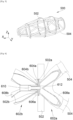
- a chassis takes for example the form of a cage, one embodiment of which is shown in Fig. 5
- the chassis 500 comprises a plurality of arches 502 or ribs, here five, arranged one after the other along a longitudinal direction of the aircraft and between two successive arches 502, beams 504 or spars fixed by their ends to the two successive arches 502.
- the beams 504 are fixed to each arch 502 by fittings fixed to the arch 502 and one embodiment of which is shown in Fig. 6 .
- Fig. 6 shows an arch 502 and two beams 504 fixed on either side of the arch 502 at the same fixing point by means of a first fitting 602a and a second fitting 602b.
- the arch 502 has a first surface 502a inscribed in a first plane and a second surface 502b inscribed in a second plane parallel to the first plane.
- the first fitting 602a has a first base 604a which is fixed to the arch 502 by a plurality of fixing means 606a such as bolts.
- the first base 604a bears against the first surface 502a of the arch 502.
- the first fitting 602a has two sleeves 608a secured to the first base 604a, where each receives by fitting one end of a beam 504.
- the second fitting 602b has a second base 604b which bears against the second surface 502b of the arch 502 which is opposite the first surface 502a.
- the second bracket 602b is fixed to the first bracket 602a by a screw 610 with a head and a threaded rod, where the threaded rod passes through the second bracket 602b and the arch 502, to screw into a tapped hole in the first bracket 602a and where the head comes to bear against a portion of the second bracket 602b so as to sandwich the arch 502 between the first bracket 602a and the second bracket 602b.
- the second bracket 602b has two sleeves 608b integral with the second base 604b, where each receives by fitting one end of a beam 504.
- the first fitting 602a also includes a centering stud 612 which fits into a bore of the second fitting 602b provided for this purpose.
- the design is such that the screw 610 must be perpendicular to the arch 502 and because of the bulk, the beams 504 all have an angle with the arch 502 and it is not possible to have a beam perpendicular to said arch 502.
- An object of the present invention is to provide an assembly for fixing beams, where the orientation of the beams has greater freedom.
- the clamping screw is in an oblique position relative to the support plane, which allows, among other things, the installation of beams perpendicular to the support plane.
- the bore is coaxial with one of the sleeves of the first fitting.
- the head of the clamping screw is housed in a barrel of the second fitting, one of the cylindrical surfaces of which carries a first thread, and the assembly comprises an additional beam, one end of which carries a second thread complementary to the first thread.
- the stud has an outer surface which fits into an inner surface of the housing, and the outer surface and the inner surface are parallel to the axis of the bore.
- the stud has an outer surface which fits into an inner surface of the housing, and the outer surface and the inner surface are perpendicular to the support plane.
- the invention also proposes a chassis for fixing a propulsion assembly to a wing of an aircraft, said chassis comprising a plurality of arches and a plurality of beams, where the beams are fixed to the arches using assemblies according to one of the preceding variants, where each arch constitutes a support plate and where each sleeve receives by fitting one end of a beam.
- the invention also proposes an aircraft comprising a chassis according to the preceding variant, a propulsion assembly and a wing where the propulsion assembly is fixed to the chassis and where the chassis is fixed to the wing.
- X is the longitudinal direction which corresponds to the axis of the aircraft oriented positively forward in the direction of advancement of the aircraft
- Y is the transverse direction which is horizontal when the aircraft is on the ground
- Z is the vertical direction or vertical height when the aircraft is on the ground, these three directions X, Y and Z being orthogonal to each other.
- FIG. 1 shows an aircraft 100 which has a fuselage 22 on either side of which a wing 24 is fixed. Under each wing 24 is fixed at least one propulsion unit 151 which comprises a nacelle 26 comprising cowls 28 forming an aerodynamic exterior surface.
- the propulsion unit 151 also includes an engine which is housed in the nacelle 26 and which here takes the form of a propeller engine, but which may be of another type.
- the aircraft 100 also includes a chassis (also called a mast) such as that shown in the Fig. 5 .
- the chassis 500 comprises structural elements connected together to form a cage and the chassis 500 here comprises a plurality of arches 502 arranged one after the other parallel to the longitudinal direction X and between two successive arches 502, and beams 504 fixed by their ends to the two successive arches 502.
- the chassis 500, the arches 502 and the beams 504 can take other forms.
- Such a chassis 500 constitutes a mast for attaching the propulsion assembly 151 under the wing 24 where the propulsion assembly 151 is fixed to the chassis 500 and where the chassis 500 is fixed to the wing 24.
- FIG. 2 shows the junction between a support plate 102 and beams 50 within the framework of an assembly 100 according to a first embodiment of the invention.
- Fig. 3 shows this assembly 100 according to the first embodiment of the invention and the Fig. 4 shows an assembly 400 according to a second embodiment of the invention.
- the assembly 100, 400 is more particularly described in the case of a chassis for fixing an aircraft engine, but it can be implemented in other fields when its beams must be fixed to a support plate, for example in a generally perpendicular manner.
- the support plate 102 can be an arch or another flat element.
- the assembly 100, 400 is therefore intended for fixing the beams 50 which here number four but depending on the size, and in particular the diameters of the beams 50, it is possible to have more or less, that is to say at least one.
- the assembly 100, 400 thus comprises the support plate 102 having a through opening 103 and where the support plate 102 has two faces parallel to each other and parallel to a support plane P, where the support plate 102 has a first face 102a and a second face 102b opposite the first face 102a.
- the assembly 100, 400 also comprises a first fitting 104a which comes against the first face 102a and a second fitting 104b which comes against the second face 102b.
- the first fitting 104a has a first base 106a which bears against the first face 102a to which it is fixed directly using fixing means 108 such as bolts which pass through the support plate 102 and the first base 106a.
- the first fitting 104a When the first fitting 104a is in place against the first face 102a, the first fitting 104a has on the side opposite the first face 102a, at least one first sleeve 110a, here two in number, and each first sleeve 110a receives by fitting one end of a beam 50.
- the or each first sleeve 110a is integral with the first base 106a.
- the fitting is preferably carried out by force and/or by welding.
- one of the beams 50 is perpendicular to the support plate 102, that is to say to the support plane P, but other orientations remain possible.
- the first fitting 104a also has a stud 312, 412 which extends through the opening 103 of the support plate 102 to end up on the other side of the support plate 102 relative to the first base 106a.
- the stud 312, 412 is also integral with the first base 106a.
- the stud 312, 412 has a bore 114 with an axis 114a.
- the bore 114 is here through but it could be blind.
- the bore 114 opens at least on the side opposite the first base 106a, that is to say on the side of the second fitting 104b.
- the second fitting 104b has a second base 106b which rests against the second face 102b.
- the second fitting 104b When the second fitting 104b is in place against the second face 102b, the second fitting 104b has on the side opposite the second face 102b, at least one second sleeve 110b, here also two in number, and each second sleeve 110b receives by fitting one end of a beam 50.
- the or each second sleeve 110b is integral with the second base 106b.
- the fitting is preferably carried out by force and/or by welding.
- one of the beams 50 is perpendicular to the support plate 102, that is to say to the support plane P, but other orientations remain possible.
- the second fitting 104b also has a housing 314, 414 which is therefore hollowed out inside the second fitting 104b and in which the stud 312, 412 of the first fitting 104a is housed.
- the housing 314, 414 has a clamping wall 316, 416 which is pierced with a hole 316a, 416a opposite, that is to say aligned with the bore 114 of the stud 312, 412.
- the clamping wall 316, 416 is then opposite the bore 114 of the stud 312, 412 and is preferably perpendicular to the axis 114a of the bore 114.
- the assembly 100 also comprises a clamping screw 118 which has a head and a threaded rod, where the threaded rod is screwed into the bore 114 which is tapped for this purpose, bringing the head into abutment against the clamping wall 316, 416, which is thus sandwiched between the head of the clamping screw 118 and the stud 312, 412.
- the threaded rod of the clamping screw 118 is thus introduced into the hole 316a, 416a to screw into the bore 114 of the stud 312, 412.
- the second fitting 104b is therefore not fixed directly to the support plate 102, but by clamping via the first fitting 104a.
- the axis 114a of the bore 114 has with the support plane P, an angle ⁇ between 10° and 80°, and preferably between 30° and 60°.
- the bore 114 is coaxial with one of the sleeves 110a of the first fitting 104a which facilitates the production of said bore 114.
- the head of the clamping screw 118 is housed in a barrel 120 of the second fitting 104b and which is here cylindrical. Even if it is not not the case in the second embodiment of the invention, such a barrel can also be put in place.
- the barrel 120 is here coaxial with the axis 114a of the bore 114.
- One of the cylindrical surfaces of the barrel 120 carries a first thread to allow the installation of an additional beam 52 by screwing.
- one end of the additional beam 52 carries a second thread complementary to the first thread to cooperate together.
- the outer surface of the barrel 120 is threaded and the interior of the additional beam 52 is tapped.
- the stud 312, 412 has an external surface 312a, 412a, preferably cylindrical, which fits into an internal surface 314a, 414a of the housing 314, 414 to ensure translational guidance of the two fittings 104a-b relative to each other.
- the stud 312 has an outer surface 312a and the housing 314 has an inner surface 314a which are parallel to the axis 114a of the bore 114 and which therefore have the same angle ⁇ with the support plane P.
- the outer surface 312a and the inner surface 314a each take the form of a cylindrical surface coaxial with the axis 114a of the bore 114.
- the stud 412 has an outer surface 412a and the housing 414 has an inner surface 414a which are perpendicular to the support plane P.
- the outer surface 412a and the inner surface 414a each take the form of a cylindrical surface perpendicular to the support plane P.
- the head of the clamping screw 118 is blocked in rotation by blocking means 124.
- blocking means 124 can also be put in place in the first embodiment of the invention.
- the locking means 124 comprise a hexagonal crown 124a which is threaded around the hexagonal head of the clamping screw 118, and which has an extension 124 which is drilled and receives a locking screw 124c which screws into a nut 124d blocked in the second fitting 104b.
- the chassis 500 thus comprises a plurality of arches 502 and a plurality of beams 504, where the beams 504 are fixed to the arches 502 using assemblies 100, 400 as described above, where each arch 502 constitutes a support plate 102 and where each sleeve 110a-b receives by fitting one end of a beam 504.
Landscapes
- Engineering & Computer Science (AREA)
- Aviation & Aerospace Engineering (AREA)
- General Engineering & Computer Science (AREA)
- Mechanical Engineering (AREA)
- Connection Of Plates (AREA)
- Clamps And Clips (AREA)
Applications Claiming Priority (1)
| Application Number | Priority Date | Filing Date | Title |
|---|---|---|---|
| FR2304043A FR3148063A1 (fr) | 2023-04-21 | 2023-04-21 | Ensemble pour la fixation de poutres comportant une plaque support et deux ferrures de part et d’autre de la plaque support |
Publications (2)
| Publication Number | Publication Date |
|---|---|
| EP4450397A1 true EP4450397A1 (de) | 2024-10-23 |
| EP4450397B1 EP4450397B1 (de) | 2026-04-08 |
Family
ID=87035868
Family Applications (1)
| Application Number | Title | Priority Date | Filing Date |
|---|---|---|---|
| EP24170929.4A Active EP4450397B1 (de) | 2023-04-21 | 2024-04-18 | Anordnung zur befestigung von balken mit einer trägerplatte und zwei beschlagteilen an beiden seiten der trägerplatte |
Country Status (4)
| Country | Link |
|---|---|
| US (1) | US12397919B2 (de) |
| EP (1) | EP4450397B1 (de) |
| CN (1) | CN118811096A (de) |
| FR (1) | FR3148063A1 (de) |
Citations (4)
| Publication number | Priority date | Publication date | Assignee | Title |
|---|---|---|---|---|
| FR2993535A1 (fr) * | 2012-07-20 | 2014-01-24 | Airbus Operations Sas | Ensemble propulsif comprenant un turboreacteur a double flux de tres grand diametre et son dispositif d'accrochage sous la voilure d'un aeronef |
| US20160280381A1 (en) * | 2013-11-18 | 2016-09-29 | Lord Corporation | Turboprop engine attachment systems and methods |
| US20190352905A1 (en) * | 2016-07-26 | 2019-11-21 | Jiangsu Ernest Technology Co. Ltd. | A connector for joining bars |
| US20230003243A1 (en) | 2021-07-02 | 2023-01-05 | Blokable, Llc | Resilient connector and methods of use of same |
Family Cites Families (3)
| Publication number | Priority date | Publication date | Assignee | Title |
|---|---|---|---|---|
| FR2657925B1 (fr) * | 1990-02-02 | 1992-04-17 | Snecma | Dispositif de fixation sur panneau de type sandwich. |
| US7097509B2 (en) * | 2004-04-22 | 2006-08-29 | Cooper Technologies Company | Filtered terminal block assembly |
| JP7487080B2 (ja) * | 2020-11-26 | 2024-05-20 | 株式会社プロスパイラ | 防振装置の製造方法、防振装置のストッパ及び防振装置 |
-
2023
- 2023-04-21 FR FR2304043A patent/FR3148063A1/fr not_active Ceased
-
2024
- 2024-04-17 US US18/637,748 patent/US12397919B2/en active Active
- 2024-04-18 EP EP24170929.4A patent/EP4450397B1/de active Active
- 2024-04-19 CN CN202410475661.3A patent/CN118811096A/zh active Pending
Patent Citations (4)
| Publication number | Priority date | Publication date | Assignee | Title |
|---|---|---|---|---|
| FR2993535A1 (fr) * | 2012-07-20 | 2014-01-24 | Airbus Operations Sas | Ensemble propulsif comprenant un turboreacteur a double flux de tres grand diametre et son dispositif d'accrochage sous la voilure d'un aeronef |
| US20160280381A1 (en) * | 2013-11-18 | 2016-09-29 | Lord Corporation | Turboprop engine attachment systems and methods |
| US20190352905A1 (en) * | 2016-07-26 | 2019-11-21 | Jiangsu Ernest Technology Co. Ltd. | A connector for joining bars |
| US20230003243A1 (en) | 2021-07-02 | 2023-01-05 | Blokable, Llc | Resilient connector and methods of use of same |
Also Published As
| Publication number | Publication date |
|---|---|
| FR3148063A1 (fr) | 2024-10-25 |
| US20240351696A1 (en) | 2024-10-24 |
| US12397919B2 (en) | 2025-08-26 |
| CN118811096A (zh) | 2024-10-22 |
| EP4450397B1 (de) | 2026-04-08 |
Similar Documents
| Publication | Publication Date | Title |
|---|---|---|
| EP2139768B1 (de) | Flugzeugmotorbefestigungspylon mit einer mit einer tonnenmutter versehenen hinteren motorbefestigung | |
| FR3068008B1 (fr) | Ensemble de motorisation pour un aeronef | |
| EP4296157B1 (de) | Flugzeug mit einem rumpf und einer durch einen rumpf lösbar befestigten platte mit befestigungsmitteln | |
| EP4484297B1 (de) | Vordermotorbefestigungssystem für einen flugzeugmotor mit kompakter struktur | |
| EP3984888B1 (de) | Einheit für ein luftfahrzeug, die einen pylon und einen flügel umfasst | |
| EP3623647A1 (de) | Verbindungsvorrichtung mit zweifacher scherung, die mit einer exzentrischen achse und exzentrischen muffen ausgestattet ist, mechanische einheit, die eine solche vorrichtung umfasst, und zusammenbauverfahren | |
| EP3623646A1 (de) | Verbindungsvorrichtung mit einfacher scherung, die mit einer exzentrischen achse und einer exzentrischen muffe ausgestattet ist, mechanische einheit, die eine solche vorrichtung umfasst, und zusammenbauverfahren | |
| WO2021104913A1 (fr) | Systeme d'attache moteur avant pour un moteur aéronef qui comporte une structure allégée | |
| EP3486174B1 (de) | Hintere motorbefestigung für einen luftfahrzeugmotor | |
| FR3132331A1 (fr) | Dispositif de liaison comprenant deux bagues excentrées à portée tronconique et/ou sphérique, aéronef ou plancher d’aéronef comprenant au moins deux parties reliées par au moins un tel dispositif de liaison | |
| FR3058986A1 (fr) | Attache arriere d'un moteur d'aeronef comportant des temoins de rupture | |
| FR3156756A1 (fr) | Ensemble propulsif pour aéronef comportant un moteur, un mât et des moyens d’accrochage du moteur au mât | |
| EP4450397B1 (de) | Anordnung zur befestigung von balken mit einer trägerplatte und zwei beschlagteilen an beiden seiten der trägerplatte | |
| EP3604137A1 (de) | Einheit für ein luftfahrzeug, die einen mast und eine vordere motorbefestigung umfasst | |
| EP4484298B1 (de) | Vordermotorbefestigungssystem für einen flugzeugmotor mit kompakter struktur | |
| EP3728039B1 (de) | Aufhängevorrichtung | |
| EP4484299A1 (de) | Vordermotorbefestigungssystem für einen flugzeugmotor mit kompakter struktur | |
| EP3792182A1 (de) | Flugzeugtriebwerksanordnung mit einer schubkraftaufnahmevorrichtung | |
| FR3131734A1 (fr) | Ensemble propulsif pour aéronef comportant un turboréacteur, un mât et des moyens d’accrochage du turboréacteur au mât | |
| FR3166936A1 (fr) | Ensemble pour la fixation de poutres comportant une plaque support et deux ferrures soudées entre elles et à la plaque support | |
| EP3715259B1 (de) | Anordung für ein luftfahrzeug mit einem mast, einer motorhalterung und einem fixiersystem zwischen dem mast und der motorhalterung | |
| EP4516678A1 (de) | Verbindung eines flügelholms und eines horizontal zueinander ausgerichteten reaktormastes | |
| EP4375194B1 (de) | Antriebssystem eines luftfahrzeugs, welches eine asymmetrische gondel aufweist | |
| EP4516668A1 (de) | Verbindung eines flügelholms und eines horizontal zueinander ausgerichteten reaktormastes | |
| EP4488178B1 (de) | Montage eines befestigungsmastes mit einem flugzeugmotor |
Legal Events
| Date | Code | Title | Description |
|---|---|---|---|
| PUAI | Public reference made under article 153(3) epc to a published international application that has entered the european phase |
Free format text: ORIGINAL CODE: 0009012 |
|
| STAA | Information on the status of an ep patent application or granted ep patent |
Free format text: STATUS: THE APPLICATION HAS BEEN PUBLISHED |
|
| AK | Designated contracting states |
Kind code of ref document: A1 Designated state(s): AL AT BE BG CH CY CZ DE DK EE ES FI FR GB GR HR HU IE IS IT LI LT LU LV MC ME MK MT NL NO PL PT RO RS SE SI SK SM TR |
|
| STAA | Information on the status of an ep patent application or granted ep patent |
Free format text: STATUS: REQUEST FOR EXAMINATION WAS MADE |
|
| 17P | Request for examination filed |
Effective date: 20250416 |
|
| GRAP | Despatch of communication of intention to grant a patent |
Free format text: ORIGINAL CODE: EPIDOSNIGR1 |
|
| STAA | Information on the status of an ep patent application or granted ep patent |
Free format text: STATUS: GRANT OF PATENT IS INTENDED |
|
| INTG | Intention to grant announced |
Effective date: 20251111 |
|
| RIC1 | Information provided on ipc code assigned before grant |
Ipc: B64D 27/40 20240101AFI20251031BHEP Ipc: F16B 7/18 20060101ALI20251031BHEP Ipc: F16B 9/00 20060101ALI20251031BHEP Ipc: B64D 27/12 20060101ALN20251031BHEP |
|
| GRAS | Grant fee paid |
Free format text: ORIGINAL CODE: EPIDOSNIGR3 |
|
| GRAA | (expected) grant |
Free format text: ORIGINAL CODE: 0009210 |
|
| STAA | Information on the status of an ep patent application or granted ep patent |
Free format text: STATUS: THE PATENT HAS BEEN GRANTED |
|
| AK | Designated contracting states |
Kind code of ref document: B1 Designated state(s): AL AT BE BG CH CY CZ DE DK EE ES FI FR GB GR HR HU IE IS IT LI LT LU LV MC ME MK MT NL NO PL PT RO RS SE SI SK SM TR |
|
| REG | Reference to a national code |
Ref country code: CH Ref legal event code: F10 Free format text: ST27 STATUS EVENT CODE: U-0-0-F10-F00 (AS PROVIDED BY THE NATIONAL OFFICE) Effective date: 20260408 Ref country code: GB Ref legal event code: FG4D Free format text: NOT ENGLISH |
|
| REG | Reference to a national code |
Ref country code: DE Ref legal event code: R096 Ref document number: 602024003737 Country of ref document: DE |