EP4484299A1 - Vordermotorbefestigungssystem für einen flugzeugmotor mit kompakter struktur - Google Patents
Vordermotorbefestigungssystem für einen flugzeugmotor mit kompakter struktur Download PDFInfo
- Publication number
- EP4484299A1 EP4484299A1 EP24184550.2A EP24184550A EP4484299A1 EP 4484299 A1 EP4484299 A1 EP 4484299A1 EP 24184550 A EP24184550 A EP 24184550A EP 4484299 A1 EP4484299 A1 EP 4484299A1
- Authority
- EP
- European Patent Office
- Prior art keywords
- axis
- engine
- attachment system
- shaft
- connecting rods
- Prior art date
- Legal status (The legal status is an assumption and is not a legal conclusion. Google has not performed a legal analysis and makes no representation as to the accuracy of the status listed.)
- Granted
Links
Images


Classifications
-
- B—PERFORMING OPERATIONS; TRANSPORTING
- B64—AIRCRAFT; AVIATION; COSMONAUTICS
- B64D—EQUIPMENT FOR FITTING IN OR TO AIRCRAFT; FLIGHT SUITS; PARACHUTES; ARRANGEMENT OR MOUNTING OF POWER PLANTS OR PROPULSION TRANSMISSIONS IN AIRCRAFT
- B64D27/00—Arrangement or mounting of power plants in aircraft; Aircraft characterised by the type or position of power plants
- B64D27/02—Aircraft characterised by the type or position of power plants
- B64D27/10—Aircraft characterised by the type or position of power plants of gas-turbine type
- B64D27/12—Aircraft characterised by the type or position of power plants of gas-turbine type within, or attached to, wings
-
- B—PERFORMING OPERATIONS; TRANSPORTING
- B64—AIRCRAFT; AVIATION; COSMONAUTICS
- B64D—EQUIPMENT FOR FITTING IN OR TO AIRCRAFT; FLIGHT SUITS; PARACHUTES; ARRANGEMENT OR MOUNTING OF POWER PLANTS OR PROPULSION TRANSMISSIONS IN AIRCRAFT
- B64D27/00—Arrangement or mounting of power plants in aircraft; Aircraft characterised by the type or position of power plants
- B64D27/40—Arrangements for mounting power plants in aircraft
-
- B—PERFORMING OPERATIONS; TRANSPORTING
- B64—AIRCRAFT; AVIATION; COSMONAUTICS
- B64D—EQUIPMENT FOR FITTING IN OR TO AIRCRAFT; FLIGHT SUITS; PARACHUTES; ARRANGEMENT OR MOUNTING OF POWER PLANTS OR PROPULSION TRANSMISSIONS IN AIRCRAFT
- B64D27/00—Arrangement or mounting of power plants in aircraft; Aircraft characterised by the type or position of power plants
- B64D27/02—Aircraft characterised by the type or position of power plants
- B64D27/16—Aircraft characterised by the type or position of power plants of jet type
- B64D27/18—Aircraft characterised by the type or position of power plants of jet type within, or attached to, wings
-
- B—PERFORMING OPERATIONS; TRANSPORTING
- B64—AIRCRAFT; AVIATION; COSMONAUTICS
- B64D—EQUIPMENT FOR FITTING IN OR TO AIRCRAFT; FLIGHT SUITS; PARACHUTES; ARRANGEMENT OR MOUNTING OF POWER PLANTS OR PROPULSION TRANSMISSIONS IN AIRCRAFT
- B64D27/00—Arrangement or mounting of power plants in aircraft; Aircraft characterised by the type or position of power plants
- B64D27/40—Arrangements for mounting power plants in aircraft
- B64D27/404—Suspension arrangements specially adapted for supporting vertical loads
-
- B—PERFORMING OPERATIONS; TRANSPORTING
- B64—AIRCRAFT; AVIATION; COSMONAUTICS
- B64D—EQUIPMENT FOR FITTING IN OR TO AIRCRAFT; FLIGHT SUITS; PARACHUTES; ARRANGEMENT OR MOUNTING OF POWER PLANTS OR PROPULSION TRANSMISSIONS IN AIRCRAFT
- B64D27/00—Arrangement or mounting of power plants in aircraft; Aircraft characterised by the type or position of power plants
- B64D27/40—Arrangements for mounting power plants in aircraft
- B64D27/406—Suspension arrangements specially adapted for supporting thrust loads, e.g. thrust links
Definitions
- the present invention relates to a front engine attachment system for an aircraft engine where the front engine attachment system is compact, as well as to an aircraft comprising at least one such front engine attachment.
- An aircraft typically has at least one engine, in particular a turbojet. Under each wing and for each engine, the aircraft has a reactor pylon which is fixed to the wing structure and which extends below the wing and the engine is suspended under the reactor pylon.
- the engine is housed in a nacelle and attached to the engine pylon by an engine attachment system comprising a front engine attachment and a rear engine attachment.
- An object of the present invention is to provide a front engine attachment system which integrates the engine pylon and the front engine attachment to reduce the height of the assembly.
- the first axis is arranged behind the vertical axis.
- the nose is made up of two fittings fixed to each other and the cylindrical stud is made up of two half-cylinders joined on the vertical median plane where each half-cylinder belongs to one of the fittings of the nose.
- FIG. 1 shows an aircraft 100 which has an engine 102, in particular a turbojet which is fixed under a reactor mast 104 itself fixed under a wing 106.
- the engine 102 generally has a shape of revolution around the longitudinal axis X.
- the aircraft 100 comprises an engine 102 under each wing 106 of the aircraft 100, but it is possible to provide several engines under each wing 106.
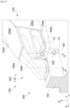
- FIG. 2 shows a front engine attachment system 150 which is fixed to the structure of the aircraft 100, here the structure of the wing 106, and extends under the wing 106 and supports the engine 102 and in particular the front part of the engine 102.
- Figs. 2 to 4 show different views of the 150 front engine mounting system.
- the front engine attachment system 150 comprises the engine pylon 104 fixed to the wing structure 106 and a front engine attachment 160 fixed between the engine pylon 104 and a front casing 103 secured to the engine 102.
- the front engine attachment system 150 comprises a vertical median plane XZ.
- the reactor mast 104 takes the form of a box which includes, among other things, at the level of a front part 163, a nose 110 which includes a male yoke 111.
- the male yoke 111 ( Fig. 4 ) is arranged between two connecting rods 162a-b which are arranged on either side of the male yoke 111 and which thus form a female yoke in which the male yoke 111 is mounted to rotate freely around a first axis 10 oriented transversely, that is to say perpendicular to the median plane XZ and therefore horizontally so as to produce a ball joint called the first ball joint, one of whose main axis of rotation is the first axis 10 and where the rotations along the other two axes are of reduced amplitudes.
- the nose 110 consists of two fittings 109a-b fixed to each other here at the level of the median plane XZ.
- the male yoke 111 is here made up of two walls 110a-b which are parallel to each other and vertical, that is to say parallel to the median plane XZ and therefore perpendicular to the transverse direction Y.
- the two walls 110a-b are joined at the median plane XZ to form the male yoke 111 and each wall 110a-b constituting the male yoke 111 belongs to one of the fittings 109a-b.
- FIG. 4 shows a section at the level of the male yoke 111 and the two female yokes 103a-b.
- the reactor mast 104 comprises an upper wall 104a, a lower wall 104b and two side walls 104c-d.
- the different walls 104a-d are integral with each other so as to form a box whose vertical section is generally trapezoidal.
- the nose 110 is fixed at the level of the front zone 163 of the reactor mast 104 by any known means such as for example by welding or bolts.
- the front zone 163 corresponds to the front ends of the walls 104a-d.
- FIG. 3 shows a section at an annular linear link where the translation axis is a vertical axis 20 and which is also called a “spigot link” 169.
- the nose 110 has a cylindrical stud 502 coaxial with the vertical axis 20 which is therefore oriented vertically and here in the vertical median plane XZ.
- the stud 502 is made up of two half-cylinders joined on the vertical median plane XZ to form the cylindrical stud 502 and each half-cylinder belongs to one of the fittings 109a-b of the nose 110.
- the cylindrical stud 502 extends downwards and is mounted to move through an annular linear connection around the vertical axis 20 relative to the front casing 103. There is therefore a ball joint connection around a main axis which is the vertical axis 20 between the cylindrical stud 502 and the front casing 103, and therefore between the nose 110 and the front casing 103. There is also a sliding connection whose direction is parallel to the vertical axis 20.
- the ball joint connection is achieved by fitting a nut 506 mounted around the cylindrical stud 502 on which the front casing 103 is hingedly mounted.
- the nut 506 is between the cylindrical stud 502 and the front casing 103 in which a hole 508 is made to allow the nut 506 to be fitted.
- the sliding connection is made between the cylindrical stud 502 and the nut 506 which is therefore mounted freely in translation along the cylindrical stud 502 parallel to the vertical axis 20.
- the male yoke 111 is arranged at the rear of the spigot connection 169 relative to the longitudinal direction X, that is to say that the first axis 10 of the first ball joint connection is at the rear of the vertical axis 20.
- the mast 104 directly incorporates the elements ensuring the fixing of the motor 102 to reduce the height necessary for this fixing.
- the X and Y forces are transmitted through the spigot connection 169.
- the front engine attachment system 150 also includes means which provide secondary force paths which compensate for a failure of the primary force path, these means constituting waiting fail-safe means.
- each connecting rod 162a-b is made up of two adjoining connecting rods.
- the cylindrical stud 502 is made up of two half-cylinders joined on the vertical median plane XZ and each half-cylinder belongs to one of the fittings 109a-b of the nose 110. Thus, in the event of failure of one of the half-cylinders, the other remains operational.
- the first shaft 165 is constituted by a first peripheral shaft 165a which is cylindrical and hollow and by a first internal shaft 165b which is fitted into the first peripheral shaft 165a.
- a first peripheral shaft 165a which is cylindrical and hollow
- a first internal shaft 165b which is fitted into the first peripheral shaft 165a.
- the second shaft 167 is comprised of a second peripheral shaft 167a which is cylindrical and hollow and a second inner shaft 167b which is fitted into the second peripheral shaft 167a.
- a second peripheral shaft 167a which is cylindrical and hollow
- a second inner shaft 167b which is fitted into the second peripheral shaft 167a.
Landscapes
- Engineering & Computer Science (AREA)
- Aviation & Aerospace Engineering (AREA)
- Pivots And Pivotal Connections (AREA)
Applications Claiming Priority (1)
| Application Number | Priority Date | Filing Date | Title |
|---|---|---|---|
| FR2306782A FR3150506A1 (fr) | 2023-06-28 | 2023-06-28 | Système d’attache moteur avant pour un moteur d’aéronef qui comporte une structure compacte |
Publications (2)
| Publication Number | Publication Date |
|---|---|
| EP4484299A1 true EP4484299A1 (de) | 2025-01-01 |
| EP4484299B1 EP4484299B1 (de) | 2026-04-08 |
Family
ID=88413319
Family Applications (1)
| Application Number | Title | Priority Date | Filing Date |
|---|---|---|---|
| EP24184550.2A Active EP4484299B1 (de) | 2023-06-28 | 2024-06-26 | Vordermotorbefestigungssystem für einen flugzeugmotor mit kompakter struktur |
Country Status (4)
| Country | Link |
|---|---|
| US (1) | US12522366B2 (de) |
| EP (1) | EP4484299B1 (de) |
| CN (1) | CN119218435A (de) |
| FR (1) | FR3150506A1 (de) |
Families Citing this family (1)
| Publication number | Priority date | Publication date | Assignee | Title |
|---|---|---|---|---|
| FR3150505A1 (fr) * | 2023-06-28 | 2025-01-03 | Airbus Operations | Système d’attache moteur avant pour un moteur d’aéronef qui comporte une structure compacte |
Citations (8)
| Publication number | Priority date | Publication date | Assignee | Title |
|---|---|---|---|---|
| GB2119857A (en) * | 1982-04-30 | 1983-11-23 | Rolls Royce | Ducted fan gas turbine engine |
| WO1993011041A1 (en) * | 1991-11-25 | 1993-06-10 | Rolls-Royce Plc | A mounting arrangement for a gas turbine engine |
| FR2905932A1 (fr) * | 2006-09-20 | 2008-03-21 | Airbus France Sa | Agencement pour attache de dispositif d'accrochage d'un moteur d'aeronef |
| US20100090056A1 (en) * | 2007-04-23 | 2010-04-15 | Airbus Operations | Pylon caisson attachment on a wing, gripping a lateral panel of the caisson |
| US20100147996A1 (en) * | 2008-12-16 | 2010-06-17 | Scott Hartshorn | Fail safe extended torque box strut-to-wing mount |
| FR3098793A1 (fr) * | 2019-07-17 | 2021-01-22 | Airbus Operations (S.A.S.) | Ensemble propulseur comprenant une attache moteur avant améliorée et aéronef comprenant au moins un tel ensemble propulseur |
| FR3103788A1 (fr) * | 2019-11-28 | 2021-06-04 | Airbus Operations | Ensemble pour un aeronef, ledit ensemble comportant un mat, une aile et un systeme de fixation entre le mat et l’aile |
| EP3945032A1 (de) * | 2020-07-31 | 2022-02-02 | Airbus Operations (S.A.S.) | Zusammenbau einer aufhängesäule und eines flügels eines luftfahrzeugs |
Family Cites Families (6)
| Publication number | Priority date | Publication date | Assignee | Title |
|---|---|---|---|---|
| FR2950118B1 (fr) * | 2009-09-14 | 2011-11-18 | Airbus Operations Sas | Palier glissant rotule et dispositif de liaison associe d'un mat d'accrochage de turbomoteur sous une voilure d'aeronef comportant un tel palier. |
| FR2965550B1 (fr) * | 2010-10-05 | 2012-11-02 | Airbus Operations Sas | Attache de type spigot pourvue d'au moins un moyen de mesure de l'effort genere par un moteur d'aeronef |
| US9248921B2 (en) * | 2013-07-11 | 2016-02-02 | Spirit Aerosystems, Inc. | Method for mounting a pylon to an aircraft |
| GB2586476A (en) * | 2019-08-20 | 2021-02-24 | Airbus Operations Ltd | Aircraft wing-pylon connection |
| FR3114801A1 (fr) * | 2020-10-02 | 2022-04-08 | Airbus Operations | Assemblage d’un mat avec une aile d’un aeronef |
| FR3133377B1 (fr) * | 2022-03-08 | 2024-03-22 | Airbus Operations Sas | Ensemble de motorisation pour un aéronef comprenant un support de charge |
-
2023
- 2023-06-28 FR FR2306782A patent/FR3150506A1/fr not_active Ceased
-
2024
- 2024-06-26 US US18/755,122 patent/US12522366B2/en active Active
- 2024-06-26 EP EP24184550.2A patent/EP4484299B1/de active Active
- 2024-06-27 CN CN202410845521.0A patent/CN119218435A/zh active Pending
Patent Citations (8)
| Publication number | Priority date | Publication date | Assignee | Title |
|---|---|---|---|---|
| GB2119857A (en) * | 1982-04-30 | 1983-11-23 | Rolls Royce | Ducted fan gas turbine engine |
| WO1993011041A1 (en) * | 1991-11-25 | 1993-06-10 | Rolls-Royce Plc | A mounting arrangement for a gas turbine engine |
| FR2905932A1 (fr) * | 2006-09-20 | 2008-03-21 | Airbus France Sa | Agencement pour attache de dispositif d'accrochage d'un moteur d'aeronef |
| US20100090056A1 (en) * | 2007-04-23 | 2010-04-15 | Airbus Operations | Pylon caisson attachment on a wing, gripping a lateral panel of the caisson |
| US20100147996A1 (en) * | 2008-12-16 | 2010-06-17 | Scott Hartshorn | Fail safe extended torque box strut-to-wing mount |
| FR3098793A1 (fr) * | 2019-07-17 | 2021-01-22 | Airbus Operations (S.A.S.) | Ensemble propulseur comprenant une attache moteur avant améliorée et aéronef comprenant au moins un tel ensemble propulseur |
| FR3103788A1 (fr) * | 2019-11-28 | 2021-06-04 | Airbus Operations | Ensemble pour un aeronef, ledit ensemble comportant un mat, une aile et un systeme de fixation entre le mat et l’aile |
| EP3945032A1 (de) * | 2020-07-31 | 2022-02-02 | Airbus Operations (S.A.S.) | Zusammenbau einer aufhängesäule und eines flügels eines luftfahrzeugs |
Also Published As
| Publication number | Publication date |
|---|---|
| EP4484299B1 (de) | 2026-04-08 |
| FR3150506A1 (fr) | 2025-01-03 |
| US20250002166A1 (en) | 2025-01-02 |
| CN119218435A (zh) | 2024-12-31 |
| US12522366B2 (en) | 2026-01-13 |
Similar Documents
| Publication | Publication Date | Title |
|---|---|---|
| EP3483069B1 (de) | Luftfahrezugtriebwerksbefestigungssystem | |
| FR3068008B1 (fr) | Ensemble de motorisation pour un aeronef | |
| EP4484297B1 (de) | Vordermotorbefestigungssystem für einen flugzeugmotor mit kompakter struktur | |
| EP4144647B1 (de) | Vorderes triebwerkbefestigungssystem für ein flugzeugtriebwerk, das eine kompakte struktur aufweist | |
| EP1773660B1 (de) | Flugzeugmotoreinheit | |
| EP2137072A1 (de) | Vorrichtung zur befestigung eines flugzeugtriebwerks und flugzeug mit mindestens einer derartigen vorrichtung | |
| WO2021104913A1 (fr) | Systeme d'attache moteur avant pour un moteur aéronef qui comporte une structure allégée | |
| EP3486174B1 (de) | Hintere motorbefestigung für einen luftfahrzeugmotor | |
| FR3073205A1 (fr) | Attache moteur d'un moteur d'aeronef | |
| EP4484299A1 (de) | Vordermotorbefestigungssystem für einen flugzeugmotor mit kompakter struktur | |
| FR3156756A1 (fr) | Ensemble propulsif pour aéronef comportant un moteur, un mât et des moyens d’accrochage du moteur au mât | |
| FR2873986A1 (fr) | Ensemble moteur pour aeronef | |
| FR3058986A1 (fr) | Attache arriere d'un moteur d'aeronef comportant des temoins de rupture | |
| EP4484298B1 (de) | Vordermotorbefestigungssystem für einen flugzeugmotor mit kompakter struktur | |
| EP4124575B1 (de) | Antriebsbaugruppe für flugzeuge mit einem turbojet, einem mast und mitteln zum befestigen des turbojet an dem mast | |
| FR3149869A1 (fr) | Dispositif pour coupler un système de propulsion à un mât reacteur d’un aeronef et aeronef correspondant | |
| EP1266826A1 (de) | Schubbefestigung eines Triebwerkes an einem Luftfahrzeug | |
| EP3728039B1 (de) | Aufhängevorrichtung | |
| EP4488178B1 (de) | Montage eines befestigungsmastes mit einem flugzeugmotor | |
| EP4491518A1 (de) | Flugzeugtriebwerkanordnung mit einer hauptstange zur motorbefestigung, sowie zwei parallel an einer querverstärkung vor einer primärstruktur eines masts | |
| FR3131734A1 (fr) | Ensemble propulsif pour aéronef comportant un turboréacteur, un mât et des moyens d’accrochage du turboréacteur au mât | |
| EP4442577B1 (de) | Reaktormast zur befestigung eines flugzeugmotors | |
| FR3095192A1 (fr) | Systeme d’attache moteur pour un moteur d’aeronef | |
| EP4450397A1 (de) | Anordnung zur befestigung von balken mit einer trägerplatte und zwei beschlagteilen an beiden seiten der trägerplatte | |
| FR3156118A1 (fr) | Mât réacteur pour le montage sur un aéronef d’un système de propulsion |
Legal Events
| Date | Code | Title | Description |
|---|---|---|---|
| PUAI | Public reference made under article 153(3) epc to a published international application that has entered the european phase |
Free format text: ORIGINAL CODE: 0009012 |
|
| STAA | Information on the status of an ep patent application or granted ep patent |
Free format text: STATUS: THE APPLICATION HAS BEEN PUBLISHED |
|
| AK | Designated contracting states |
Kind code of ref document: A1 Designated state(s): AL AT BE BG CH CY CZ DE DK EE ES FI FR GB GR HR HU IE IS IT LI LT LU LV MC ME MK MT NL NO PL PT RO RS SE SI SK SM TR |
|
| STAA | Information on the status of an ep patent application or granted ep patent |
Free format text: STATUS: REQUEST FOR EXAMINATION WAS MADE |
|
| 17P | Request for examination filed |
Effective date: 20250610 |
|
| GRAP | Despatch of communication of intention to grant a patent |
Free format text: ORIGINAL CODE: EPIDOSNIGR1 |
|
| STAA | Information on the status of an ep patent application or granted ep patent |
Free format text: STATUS: GRANT OF PATENT IS INTENDED |
|
| INTG | Intention to grant announced |
Effective date: 20251105 |
|
| GRAS | Grant fee paid |
Free format text: ORIGINAL CODE: EPIDOSNIGR3 |
|
| GRAA | (expected) grant |
Free format text: ORIGINAL CODE: 0009210 |
|
| STAA | Information on the status of an ep patent application or granted ep patent |
Free format text: STATUS: THE PATENT HAS BEEN GRANTED |
|
| AK | Designated contracting states |
Kind code of ref document: B1 Designated state(s): AL AT BE BG CH CY CZ DE DK EE ES FI FR GB GR HR HU IE IS IT LI LT LU LV MC ME MK MT NL NO PL PT RO RS SE SI SK SM TR |
|
| REG | Reference to a national code |
Ref country code: CH Ref legal event code: F10 Free format text: ST27 STATUS EVENT CODE: U-0-0-F10-F00 (AS PROVIDED BY THE NATIONAL OFFICE) Effective date: 20260408 Ref country code: GB Ref legal event code: FG4D Free format text: NOT ENGLISH |