EP4491518A1 - Flugzeugtriebwerkanordnung mit einer hauptstange zur motorbefestigung, sowie zwei parallel an einer querverstärkung vor einer primärstruktur eines masts - Google Patents
Flugzeugtriebwerkanordnung mit einer hauptstange zur motorbefestigung, sowie zwei parallel an einer querverstärkung vor einer primärstruktur eines masts Download PDFInfo
- Publication number
- EP4491518A1 EP4491518A1 EP24181952.3A EP24181952A EP4491518A1 EP 4491518 A1 EP4491518 A1 EP 4491518A1 EP 24181952 A EP24181952 A EP 24181952A EP 4491518 A1 EP4491518 A1 EP 4491518A1
- Authority
- EP
- European Patent Office
- Prior art keywords
- engine
- yoke
- safety
- connecting rod
- bore
- Prior art date
- Legal status (The legal status is an assumption and is not a legal conclusion. Google has not performed a legal analysis and makes no representation as to the accuracy of the status listed.)
- Granted
Links
Images


Classifications
-
- B—PERFORMING OPERATIONS; TRANSPORTING
- B64—AIRCRAFT; AVIATION; COSMONAUTICS
- B64D—EQUIPMENT FOR FITTING IN OR TO AIRCRAFT; FLIGHT SUITS; PARACHUTES; ARRANGEMENT OR MOUNTING OF POWER PLANTS OR PROPULSION TRANSMISSIONS IN AIRCRAFT
- B64D27/00—Arrangement or mounting of power plants in aircraft; Aircraft characterised by the type or position of power plants
- B64D27/02—Aircraft characterised by the type or position of power plants
- B64D27/16—Aircraft characterised by the type or position of power plants of jet type
- B64D27/18—Aircraft characterised by the type or position of power plants of jet type within, or attached to, wings
-
- B—PERFORMING OPERATIONS; TRANSPORTING
- B64—AIRCRAFT; AVIATION; COSMONAUTICS
- B64D—EQUIPMENT FOR FITTING IN OR TO AIRCRAFT; FLIGHT SUITS; PARACHUTES; ARRANGEMENT OR MOUNTING OF POWER PLANTS OR PROPULSION TRANSMISSIONS IN AIRCRAFT
- B64D27/00—Arrangement or mounting of power plants in aircraft; Aircraft characterised by the type or position of power plants
- B64D27/40—Arrangements for mounting power plants in aircraft
-
- B—PERFORMING OPERATIONS; TRANSPORTING
- B64—AIRCRAFT; AVIATION; COSMONAUTICS
- B64D—EQUIPMENT FOR FITTING IN OR TO AIRCRAFT; FLIGHT SUITS; PARACHUTES; ARRANGEMENT OR MOUNTING OF POWER PLANTS OR PROPULSION TRANSMISSIONS IN AIRCRAFT
- B64D27/00—Arrangement or mounting of power plants in aircraft; Aircraft characterised by the type or position of power plants
- B64D27/02—Aircraft characterised by the type or position of power plants
- B64D27/10—Aircraft characterised by the type or position of power plants of gas-turbine type
- B64D27/12—Aircraft characterised by the type or position of power plants of gas-turbine type within, or attached to, wings
-
- B—PERFORMING OPERATIONS; TRANSPORTING
- B64—AIRCRAFT; AVIATION; COSMONAUTICS
- B64D—EQUIPMENT FOR FITTING IN OR TO AIRCRAFT; FLIGHT SUITS; PARACHUTES; ARRANGEMENT OR MOUNTING OF POWER PLANTS OR PROPULSION TRANSMISSIONS IN AIRCRAFT
- B64D27/00—Arrangement or mounting of power plants in aircraft; Aircraft characterised by the type or position of power plants
- B64D27/40—Arrangements for mounting power plants in aircraft
- B64D27/402—Arrangements for mounting power plants in aircraft comprising box like supporting frames, e.g. pylons or arrangements for embracing the power plant
-
- B—PERFORMING OPERATIONS; TRANSPORTING
- B64—AIRCRAFT; AVIATION; COSMONAUTICS
- B64D—EQUIPMENT FOR FITTING IN OR TO AIRCRAFT; FLIGHT SUITS; PARACHUTES; ARRANGEMENT OR MOUNTING OF POWER PLANTS OR PROPULSION TRANSMISSIONS IN AIRCRAFT
- B64D27/00—Arrangement or mounting of power plants in aircraft; Aircraft characterised by the type or position of power plants
- B64D27/40—Arrangements for mounting power plants in aircraft
- B64D27/404—Suspension arrangements specially adapted for supporting vertical loads
Definitions
- the present application relates to an aircraft propulsion unit comprising a front engine attachment comprising a main connecting rod, as well as two safety connecting rods arranged in parallel with said main connecting rod, connected to a front transverse reinforcement of a primary structure of a mast and to an aircraft engine.
- the present invention also relates to an aircraft comprising at least one such propulsion unit.
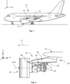
- an aircraft 10 comprises wings 12, and at least one propulsion unit 14 positioned under each of the wings 12.
- the propulsion unit 14 comprises a mast 16 fixed under the wing 12 and an engine 18 fixed under the mast 16. More precisely, the mast 16 comprises a primary structure 20 which is connected to the engine 18 by an engine attachment 22 and to the wing 12 by a wing attachment 24.
- X is called the longitudinal direction of the mast 16, this direction X being parallel to the axis of rotation A18 of the engine 18 and to a longitudinal axis of the aircraft 10.
- Y is called the transverse direction of the mast 16 which is horizontal when the aircraft 10 is on the ground and perpendicular to the axis of rotation A18 of the engine 18, and Z is the vertical direction or vertical height when the aircraft 10 is on the ground and perpendicular to the axis of rotation A18 of the engine 18, these three directions X, Y and Z being orthogonal to each other.
- the terms “front” and “rear” are to be considered in relation to a direction of advancement of the aircraft 10 during operation of the engine 18 (direction of flow of the gases, the front corresponding to the admission of the gases (air) into the engine and the rear corresponding to the exhaust of the gases (combustion gases)), this direction being represented schematically by the arrow A.
- the terms “port” and “starboard” are also to be considered in relation to the direction of advancement A of the aircraft 10 and in relation to the longitudinal direction X.
- the engine attachment 22 comprises a front engine attachment 26, a rear engine attachment 28 and a pair of thrust rods 30 ensuring the absorption of thrust forces.
- the primary structure 20 of the mast 16 comprises upper and lower spars 20.1, right and left side panels 20.2 and a plurality of transverse reinforcements 20.3 connecting the upper and lower spars 20.1 and the right and left side panels 20.2.
- a front transverse reinforcement 20.3 is positioned at the front of the primary structure 20 of the mast, and extends at least partly over the lower spar 20.1.
- This front transverse reinforcement 20.3 has a bearing surface for fixing the front engine attachment 26, positioned in a horizontal plane, under said front transverse reinforcement.
- the transverse beam 32 For each beam connecting axis 42, 48, the transverse beam 32 comprises a yoke having two wings 32.1, 32.2 between which the first or second connecting rod 38, 44 is positioned.
- the engine casing (not shown in the figure 3 ) comprises a yoke having two wings between which the first or second connecting rod 38, 44 is positioned.
- the transverse beam 32 comprises a yoke having a wing 36.1, which is positioned between two wings of a yoke (not visible in the figure 3 ) of the engine crankcase.
- Such a front engine attachment 26 has a so-called "fail safe” interface separated from the primary force paths.
- the connecting rods 38, 44 correspond to the primary force paths, and allow, in nominal configuration, to ensure the recovery of the forces
- the safety connecting axis 36 corresponds to a standby force path, called safety, and allows, in degraded configuration of one of the connecting rods 38, 44, or of one of the yokes 32.1, 32.2 of the transverse beam 32, or of one of the yokes of the engine casing, to ensure the recovery of the forces.
- the distribution of forces can be significantly modified between the nominal and degraded configurations of the front engine mount, which can make the dimensioning of the parts complex.
- the present invention relates to an aircraft propulsion unit comprising a primary structure of a mast, an engine, and a front engine attachment connecting the primary structure and the engine, the primary structure comprising upper and lower spars, right and left side panels and a front transverse reinforcement, the front transverse reinforcement comprising, for each right and left side panel, a first yoke projecting relative to said side panel, and having two first wings, each first wing having a first bore, the engine comprising at least one second yoke having two second wings, each second wing having a second bore.
- the propulsion unit according to the invention makes it possible to minimize the number of pending interfaces, by eliminating the pending yokes on the engine casing and on the front engine mount, and therefore to simplify the design of the engine casing and the front engine mount.
- This propulsion unit also makes it possible to maintain the distribution of forces between the nominal configuration and the degraded configuration of the front engine mount, which simplifies the dimensioning of the parts.
- the presence of the safety connecting rods makes it possible to ensure the continuity of the passage of forces in all conditions.
- the engine comprises a third yoke having two third wings, each third wing having a seventh bore, the second and third safety connecting rods being positioned between the third wings of the third yoke of the engine.
- the presence of the third engine yoke ensures continuity of the passage of forces in all conditions (nominal or degraded of the second engine yoke).
- the second and third safety connecting rods are separated from the third engine yoke by a first clearance.
- this first clearance makes it possible to cover manufacturing tolerances, as well as displacements due to the articulation of the junction between the front transverse reinforcement and the engine, in a degraded situation.
- This clearance also allows rotation of the third yoke of the engine relative to the second and third connecting rods.
- the first engine connecting pin is inserted into the sixth bores of the second and third safety connecting rods with a second clearance. This second clearance allows the second and third safety connecting rods to be kept ready.
- the second and third safety connecting rods are separated from the second engine yoke by a third clearance.
- this third clearance makes it possible to cover manufacturing tolerances, as well as displacements due to the articulation of the junction between the front transverse reinforcement and the engine, in a nominal situation.
- This clearance also allows rotation of the second engine yoke relative to the first connecting rod.
- the front engine attachment comprises, for each first wing of the first yoke of the front transverse reinforcement, a reinforcement ring arranged in the first bore.
- the first reinforcement connecting pin has an eighth bore
- the propulsion unit comprises a second safety reinforcement connecting pin inserted into the eighth bore of the first reinforcement connecting pin.
- the presence of a double reinforcement connection axis ensures the continuity of the passage of forces in all conditions (nominal or degraded of the first reinforcement connection axis).
- the first engine connecting shaft has a ninth bore
- the propulsion unit comprises a second safety engine connecting shaft inserted into the ninth bore of the first engine connecting shaft.
- the presence of a double engine connection axis ensures the continuity of the passage of forces in all conditions (nominal or degraded from the first engine connection axis).
- the present invention also relates to an aircraft comprising at least one propulsion unit according to the invention.
- a front engine attachment 60 of a propulsion unit connecting a primary structure 62 of an aircraft pylon and an engine 64 is shown. In these figures, only a portion of the engine casing 64 and the primary structure 62 are shown. At least one propulsion unit of an aircraft is equipped with such a front engine attachment 60.
- the primary structure 62 comprises an upper spar (not shown in the Figures 4 to 7 ) and a lower spar 62.1, a right side panel 66.1 and a left side panel 66.2, as well as a front transverse reinforcement 68.
- the right and left side panels 66.1, 66.2 extend in planes parallel to the XZ plane.
- the front transverse reinforcement 68 extends in a plane parallel to the YZ plane.
- the front transverse reinforcement 68 comprises, for each right and left side panel 66.1, 66.2, a female yoke 70 projecting relative to said right or left side panel 66.1, 66.2.
- the yoke 70 extends in a plane parallel to the YZ plane, and therefore transversely to the right and left side panels 66.1, 66.2.
- the yoke 70 has two wings 72, 74, each of which has a bore 76, 78 whose axis is parallel to the longitudinal direction X.
- the engine 64 comprises at least one female yoke 80, projecting towards the primary structure 62, and which has two wings 82, 84.
- the yoke 80 extends along a plane parallel to the Y-Z plane.
- Each wing 82, 84 has a bore 86, 88 whose axis is parallel to the longitudinal direction X.
- the front engine attachment 60 comprises a connecting rod 90, called main or central, which extends in a plane parallel to the YZ plane, and which has a first bore 92 at its first end 90.1 and a second bore 94 at its second end 90.2.
- the bores 92, 94 extend along an axis parallel to the longitudinal direction X.
- the first end 90.1 of the main connecting rod 90 is positioned between the wings 72, 74 of the yoke 70 of the front transverse reinforcement 68 and the second end 90.2 of the main connecting rod 90 is positioned between the wings 82, 84 of the yoke 80 of the engine 64.
- the yoke 70 of the front transverse reinforcement 68 and the yoke 80 of the engine 64 are therefore substantially aligned, such that the wings 72, 74 of the yoke 70 and the wings 82, 84 of the yoke 80 are arranged on either side of the main connecting rod 90.
- the front engine attachment 60 also comprises two connecting rods 96, 98, called safety or lateral.
- Each safety connecting rod 96, 98 extends in a plane parallel to the Y-Z plane, and has a first bore 100, 102 at its first end 96.1, 98.1 and a second bore 104, 106 at its second end 96.2, 98.2.
- the bores 100, 102, 104, 106 extend along an axis parallel to the longitudinal direction X.
- the yoke 70, and in particular the wings 72, 74, of the front transverse reinforcement 68 is positioned between the first end 96.1 of the safety connecting rod 96 and the first end 98.1 of the safety connecting rod 98.
- the yoke 80, and in particular the wings 82, 84, of the engine 64 is positioned between the second end 96.2 of the safety connecting rod 96 and the second end 98.2 of the safety connecting rod 98.
- the safety connecting rods 96, 98 are arranged on either side of the yoke 70 of the front transverse reinforcement 68 and the yoke 80 of the engine 64.
- the yoke 70 of the front transverse reinforcement 68 is positioned between the first ends 96.1, 98.1 of the safety connecting rods 96, 98
- the yoke 80 of the engine 64 is positioned between the second ends 96.2, 98.2 of the safety connecting rods 96, 98.
- the safety connecting rods 96, 98 and the main connecting rod 90 are therefore arranged in parallel with each other, the main connecting rod 90 being arranged between the safety connecting rods 96, 98.
- the main connecting rod 90 has longitudinal dimensions (in the longitudinal direction X), transverse dimensions (in the transverse direction Y) and vertical dimensions (in the vertical direction Z) greater than the longitudinal, transverse and vertical dimensions of the safety connecting rods 96, 98.
- the safety connecting rods 96, 98 are substantially identical.
- the front engine attachment 60 comprises a first reinforcement connecting pin 108, called the main pin, which has a bore 110 whose axis is parallel to the longitudinal direction X.
- the first reinforcement connecting pin 108 extends along an axis parallel to the longitudinal direction X.
- the first reinforcement connecting pin 108 is arranged in the bore 100 of the safety connecting rod 96, in the bore 76 of the wing 72 of the yoke 70 of the front transverse reinforcement 68, in the bore 92 of the main connecting rod 90, in the bore 78 of the wing 74 of the yoke 70, and in the bore 104 of the safety connecting rod 98.
- the bores 100, 76, 92, 78, 104 are coaxial.
- the first reinforcement connecting pin 108 makes it possible to connect the front engine attachment 60 to the front transverse reinforcement 68.
- the front engine attachment 60 comprises a second safety reinforcement connecting pin 112 arranged in the bore 110 of the first reinforcement connecting pin 108.
- the first reinforcement connecting pin 108 and the second safety reinforcement connecting pin 112 form a double reinforcement connecting pin between the front transverse reinforcement 68 and the front engine attachment 60.
- second safety reinforcement connection axis 112 ensures continuity of the passage of forces in all conditions, even in the event of a degraded situation of the first reinforcement connection axis 108.
- the external diameter (radial dimension in the longitudinal direction X) of the second safety reinforcement connecting pin 112 is substantially equal to the diameter of the bore 110 of the first reinforcement connecting pin 108, so that the safety reinforcement connecting pin 112 is forcibly inserted into the bore 110 of the main reinforcement connecting pin 108.
- the outer diameter of the first reinforcement connecting pin 108 is substantially equal to the diameter of the bore 100, 104 of the safety connecting rod 96, 98, as well as to the diameter of the bore 92 of the main connecting rod 90. A rotation of the main connecting rod 90 or the safety connecting rods 96, 98 about the first reinforcement connecting pin 108 is permitted.
- the main connecting rod 90 and the safety connecting rods 96, 98 are mounted on the first reinforcement connecting pin 108 with a tight fit.
- the front engine attachment 60 comprises, for each wing 72, 74 of the yoke 70 of the front transverse reinforcement 68, a reinforcing ring 120, 122 comprising a hollow body at least partially positioned in the bore 76, 78 of said wing 72, 74.
- the external diameter of the body of the reinforcing ring 120, 122 is substantially equal to the diameter of the bore 76, 78 of the wing 72, 74 of the yoke 70 of the front transverse reinforcement 68, such that the reinforcing ring 120, 122 is forcibly inserted into the bore 76, 78 of the wing 72, 74 of the yoke 70.
- the external diameter of the first reinforcement connecting pin 108 is substantially equal to the internal diameter of the body of the reinforcing ring 120, 122.
- the front engine attachment 60 comprises a first engine connecting shaft 114, called the main shaft, which has a bore 116 whose axis is parallel to the longitudinal direction X.
- the first engine connecting shaft 114 extends along an axis parallel to the longitudinal direction X.
- the first engine connecting shaft 114 is arranged in the bore 102 of the safety connecting rod 96, in the bore 86 of the wing 82 of the yoke 80 of the engine 64, in the bore 94 of the main connecting rod 90, in the bore 88 of the wing 84 of the yoke 80, and in the bore 106 of the safety connecting rod 98.
- the bores 102, 86, 94, 88, 106 are coaxial.
- the first engine connecting shaft 114 makes it possible to connect the front engine attachment 60 to the engine 64.
- the front engine attachment 60 comprises a second safety engine connection pin 118 arranged in the bore 116 of the first engine connection pin 114.
- the first engine connection pin 114 and the second safety engine connection pin 118 form a double reinforcement connecting shaft between the front transverse reinforcement 68 and the front engine attachment 60.
- the second safety engine connecting shaft 118 ensures continuity of the passage of forces in all conditions, even in the event of a degraded situation for the first engine connecting shaft 114.
- the external diameter of the second safety engine connecting shaft 118 is substantially equal to the diameter of the bore 116 of the first engine connecting shaft 114, such that the safety engine connecting shaft 118 is force-fitted into the bore 116 of the main engine connecting shaft 114.
- the main connecting rod 90 is connected to the engine 64 by the first engine connecting pin 114 and to the front transverse reinforcement 68 by the first reinforcement connecting pin 108, the main connecting rod 90 being positioned between the wings 72, 74 of the yoke 70 of the front transverse reinforcement 68 and between the wings 82, 84 of the yoke 80 of the engine 64.
- the safety connecting rods 96, 98 are connected to the engine 64 by the first engine connecting pin 114 and to the front transverse reinforcement 68 by the first reinforcement connecting pin 108, the yoke 70 of the front transverse reinforcement 68 and the yoke 80 of the engine 64 being positioned between the safety connecting rods 96, 98.
- the outer faces 72.1, 74.1 of the yoke 70 that is to say the outer face 72.1 of the wing 72 and the outer face 74.1 of the wing 74 (as opposed to the inner faces 72.2, 74.2 of the wings 72, 74 which are opposite one another), are substantially aligned, in the longitudinal direction X, with the outer faces 82.1, 84.1 of the yoke 80, that is to say the outer face 82.1 of the wing 82 and the outer face 84.1 of the wing 84 (as opposed to the inner faces 82.2, 84.2 of the wings 82, 84 which are opposite one another).
- the longitudinal dimension of the wings 72, 74 of the yoke 70 of the front transverse reinforcement 68 is less than the longitudinal dimension of the wings 82, 84 of the yoke 80 of the engine 64.
- the distance in the longitudinal direction X between the wings 72, 74 of the yoke 70 is greater than the distance between the wings 82, 84 of the yoke 80 (distance between the inner faces 82.2, 84.2).
- the longitudinal dimension of the main connecting rod 90 is substantially equal to the distance in the longitudinal direction X between the wings 82, 84 of the yoke 80 (distance between the inner faces 82.2, 84.2).
- a space E1 is present between the main connecting rod 90 and each inner face 72.2, 74.2 of the wing 72, 74 of the yoke 70 of the front transverse reinforcement 68.
- the reinforcement ring 120, 122 comprises a radial protrusion 120.1, 122.1, of diameter greater than the external diameter of the body of the reinforcement ring 120, 122, which extends from the body of the reinforcement ring 120, 122 between the main connecting rod 90 and the wings 72, 74 of the yoke 70.
- the longitudinal dimension of the radial protrusion 120.1, 122.1 is substantially equal to the space E1.
- the space E1 between the main connecting rod 90 and the yoke 70 is filled by the radial protrusion 120.1, 122.1 of the reinforcing ring 120, 122.
- a space E2 is present between the safety connecting rod 96, 98 and the outer face 72.1, 74.1 of the wing 72, 74 of the yoke 70 of the front transverse reinforcement 68.
- the body of the reinforcement ring 120, 122 extends beyond the bore 76, 78 in the direction of the safety connecting rod 96, 98, and in particular in the space E2.
- the space E2 between the safety connecting rod 96, 98 and the yoke 70 is filled by the body of the reinforcement ring 120, 122.
- a clearance J1 is present between the safety connecting rod 96, 98 and the outer face 82.1, 84.1 of the wing 82, 84 of the yoke 80 of the engine 64.
- the clearance J1 is configured to cover the manufacturing tolerances, as well as the movements due to the articulation of the junction between the front transverse reinforcement 68 and the engine 64, in a nominal situation.
- the clearance J1 is configured to be as small as possible in order to minimize the bending of the wings 82, 84 of the yoke 80.
- the clearance J1 advantageously allows a rotation of the yoke 80 of the engine 64 relative to the main connecting rod 90.
- the main connecting rod 90 is mounted on the first engine connecting pin 114 with a tight fit.
- a clearance J2 is present between the bore 102, 106 of the safety connecting rod 96, 98 and the first engine connecting pin 114.
- the first engine connecting pin 114 is inserted into the bores 102, 106 of the safety connecting rods 96, 98 with a clearance J2.
- the clearance J2 is configured to be filled in the event of a degraded configuration.
- the safety connecting rods 96, 98 are mounted on the first reinforcement connecting pin 108 with a tight fit and on the first engine connecting pin 114 with the clearance J2.
- the safety connecting rod(s) 96, 98 or the first engine connecting shaft 114 moves to bring the wall of the bore 100, 104 of the safety connecting rod 96, 98 against the first engine connecting axis 114.
- the forces are transmitted from the yoke 80 of the engine 64 to the main connecting rod 90, then to the yoke 70 of the front transverse reinforcement 68.
- the safety connecting rods 96, 98 are "on standby", and do not allow the forces to be taken up. Indeed, the safety connecting rods 96, 98 are separated from the first engine connecting axis 114 by the clearance J2 which is not zero.
- the engine 64 which was held to the front transverse reinforcement 68 by means of the yoke 80 of the engine 64, the main connecting rod 90 and the yoke 70 of the front transverse reinforcement 68 in nominal configuration, will now be held to the front transverse reinforcement 68 by means of the yoke 80 of the engine 64, the safety connecting rods 96, 98 and the yoke 70 of the front transverse reinforcement 68 in this degraded configuration.
- the first engine connecting shaft 114 then rests in the bore 102, 106 of the safety connecting rod 96, 98, so that the clearance J2 between the first engine connecting shaft 114 and the safety connecting rods 96, 98 is zero.
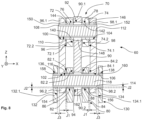
- FIG. 8 represents a front engine mount according to another embodiment.
- the engine comprises at least the first female yoke 80, projecting towards the primary structure of the mast, and which has two wings 82, 84, and a second female yoke 130, projecting towards the primary structure of the mast, and which has two wings 132, 134.
- the yokes 80, 130 extend along a plane parallel to the Y-Z plane.
- the yokes 80, 130 are arranged in parallel with each other.
- Each wing 82, 84, 132, 134 has a bore 86, 88, 136, 138 whose axis is parallel to the longitudinal direction X.
- the yoke 80 is arranged between the wings 132, 134 of the yoke 130.
- the bores 86, 88, 136, 138 are coaxial.
- the yoke 130, and in particular the wings 132, 134, of the engine is positioned around the second end 96.2 of the safety connecting rod 96 and the second end 98.2 of the safety connecting rod 98.
- the safety connecting rods 96, 98 are arranged between the wings 132, 134 of the yoke 130 of the engine, and around the yoke 80.
- the yoke 70 of the front transverse reinforcement is positioned between the first ends 96.1, 98.1 of the safety connecting rods 96, 98, while the second ends 96.2, 98.2 of the safety connecting rods 96, 98 are arranged between the wing 132 of the yoke 130 and the wing 82 of the yoke 80 for the first safety connecting rod 96, and between the wing 134 of the yoke 130 and the wing 84 of the yoke 80 for the second safety connecting rod 98.
- the front engine attachment 60 comprises, for each wing 72, 74 of the yoke 70 of the front transverse reinforcement, a first reinforcement half-ring 140, 142 comprising a hollow body at least partially positioned in the bore 76, 78 of said wing 72, 74, from the inner face 72.2, 74.2 of the wing 72, 74, and a second reinforcement half-ring 144, 146 comprising a hollow body at least partially positioned in the bore 76, 78 of said wing 72, 74, from the outer face 72.1, 74.1 of the wing 72, 74.
- the first and second reinforcement half-rings 140, 142, 144, 146 thus form a reinforcement ring for each wing 72, 74 of the yoke 70 of the front transverse reinforcement. bore 76, 78 of the wing 72, 74.
- the external diameter of the body of each reinforcement half-ring 140, 142, 144, 146 is substantially equal to the diameter of the bore 76, 78 of the wing 72, 74 of the yoke 70 of the front transverse reinforcement 68, so that each reinforcement half-ring 140, 142, 144, 146 is force-fitted into the bore 76, 78 of the wing 72, 74 of the yoke 70.
- the external diameter of the first reinforcement connecting axis 108 is substantially equal to the internal diameter of the body of each reinforcement half-ring 140, 142, 144, 146.
- the front engine attachment 60 comprises, for the main connecting rod 90, a reinforcing ring 148 positioned in the bore 92 of said main connecting rod 90.
- the external dimension of the reinforcing ring 148 is substantially equal to the dimension of the bore 92 of the main connecting rod 90, such that the reinforcing ring 148 is force-fitted into the bore 92 of the main connecting rod 90.
- the external diameter of the first reinforcing connecting pin 108 is substantially equal to the internal diameter of the reinforcing ring 148.
- the front engine attachment 60 comprises, for each safety connecting rod 96, 98, a reinforcing ring 150, 152 positioned in the bore 100, 104 of said safety connecting rod 96, 98.
- the external diameter of the reinforcing ring 150, 152 is substantially equal to the diameter of the bore 100, 104 of the safety connecting rod 96, 98, such that the reinforcing ring 150, 152 is force-fitted into the bore 100, 104 of the safety connecting rod 96, 98.
- the external diameter of the first reinforcing connecting pin 108 is substantially equal to the internal diameter of the reinforcing ring 150, 152.
- the reinforcing ring 150 extends beyond the bore 100 of the safety connecting rod 96, in the longitudinal direction X (here in the direction of the wing 72 of the yoke 70), and the reinforcing half-ring 144 extends beyond the bore 76 of the wing 72 of the yoke 70, in a direction opposite to the longitudinal direction X (here in the direction of the safety connecting rod 96).
- the reinforcing ring 150 and the reinforcing half-ring 144 abut against each other, while a space results between the safety connecting rod 96 and the wing 72 of the yoke 70.
- the reinforcing ring 148 extends beyond the bore 92 of the main connecting rod 90, on either side of the bore 92.
- the reinforcing half-ring 140 extends beyond the bore 76 of the wing 72 of the yoke 70 in the longitudinal direction X, and the reinforcing half-ring 142 extends beyond the bore 78 of the wing 74 of the yoke 70, in a direction opposite to the longitudinal direction X.
- the reinforcing ring 148 and the reinforcing half-ring 140, 142 abut against each other, while a space results between the main connecting rod 90 and the wing 72, 74 of the yoke 70.
- the reinforcing ring 152 extends beyond the bore 104 of the safety connecting rod 98, in a direction opposite to the longitudinal direction X (here in the direction of the wing 74 of the yoke 70), and the reinforcing half-ring 146 extends beyond the bore 78 of the wing 74 of the yoke 70, in the longitudinal direction X (here in the direction of the safety connecting rod 98).
- the reinforcing ring reinforcement 152 and the reinforcement half-ring 146 are in abutment against each other, while a space results between the safety connecting rod 98 and the wing 74 of the yoke 70.
- the front engine attachment 60 comprises, for each wing 82, 84, 132, 134 of the yoke 80, 130 of the engine, a reinforcing ring 154, 156, 158, 160 positioned in the bore 86, 88, 136, 138 of said wing 82, 84, 132, 134.
- the external diameter of the reinforcing ring 154, 156, 158, 160 is substantially equal to the diameter of the bore 86, 88, 136, 138 of the wing 72, 74 of the yoke 70 of the front transverse reinforcement 68, so that the reinforcing ring 154, 156, 158, 160 is force-fitted into the bore 86, 88, 136, 138 of the wing 72, 74 of the yoke 70.
- the external diameter of the first reinforcement connection axis 108 is substantially equal to the internal diameter of the reinforcement ring 154, 156, 158, 160.
- the front engine attachment 60 comprises, for the main connecting rod 90, a reinforcing ring 162 positioned in the bore 94 of said main connecting rod 90.
- the external dimension of the reinforcing ring 162 is substantially equal to the dimension of the bore 94 of the main connecting rod 90, such that the reinforcing ring 162 is force-fitted into the bore 94 of the main connecting rod 90.
- the external diameter of the first reinforcing connecting pin 108 is substantially equal to the internal diameter of the reinforcing ring 162.
- the reinforcing ring 162 extends beyond the bore 94 of the main connecting rod 90, on either side of the bore 94.
- the reinforcing ring 154 extends beyond the bore 86 of the wing 82 of the yoke 80 in the longitudinal direction X
- the reinforcing ring 156 extends beyond the bore 88 of the wing 84 of the yoke 80, in a direction opposite to the longitudinal direction X.
- the reinforcing ring 162 and the reinforcing ring 154, 156 abut against each other, while a space results between the main connecting rod 90 and the wing 82, 84 of the yoke 80.
- the outer faces 72.1, 74.1 of the yoke 70 are substantially aligned, in the longitudinal direction X, with the outer faces 82.1, 84.1 of the yoke 80; and the inner faces 72.2, 74.2 of the yoke 70 are substantially aligned, in the longitudinal direction X, with the inner faces 82.2, 84.2 of the yoke 80.
- the longitudinal dimension of the wings 72, 74 of the yoke 70 of the front transverse reinforcement is substantially equal to the longitudinal dimension of the wings 82, 84 of the yoke 80 of the engine.
- the distance in the longitudinal direction X between the wings 72, 74 of the yoke 70 is substantially equal to the distance between the wings 82, 84 of the yoke 80.
- the first engine connecting shaft 114 is arranged in the bore 136 of the wing 132 of the yoke 130, in the bore 102 of the safety connecting rod 96, in the bore 86 of the wing 82 of the yoke 80 of the engine 64, in the bore 94 of the main connecting rod 90, in the bore 88 of the wing 84 of the yoke 80, in the bore 106 of the safety connecting rod 98, and in the bore 138 of the wing 134 of the yoke 130.
- the forces are transmitted from the engine yoke 80 to the main connecting rod 90, then to the yoke 70 of the front transverse reinforcement.
- the safety connecting rods 96, 98 are "on standby", and do not allow the forces to be taken up; and the yoke 130 is "on standby", and does not allow the forces to be taken up.
- the forces in a first degraded configuration, where the main connecting rod 90 is faulty, the forces will be transmitted from the engine yokes 80, 130 to the safety connecting rods 96, 98, then to the yoke 70 of the front transverse reinforcement.
- the forces are transmitted from the wing 84 of the yoke 80 and from the wing 134 of the yoke 130 of the engine to the main connecting rod 90 and to the safety connecting rod 98, then to the yoke 70 of the front transverse reinforcement.
- a front engine mount according to the invention has a minimal number of safety/standby interfaces.
- the distribution of forces in this front engine mount, between a nominal configuration and a degraded configuration of such a front engine mount, is retained.
Landscapes
- Engineering & Computer Science (AREA)
- Aviation & Aerospace Engineering (AREA)
- Body Structure For Vehicles (AREA)
Applications Claiming Priority (1)
| Application Number | Priority Date | Filing Date | Title |
|---|---|---|---|
| FR2307334 | 2023-07-10 |
Publications (2)
| Publication Number | Publication Date |
|---|---|
| EP4491518A1 true EP4491518A1 (de) | 2025-01-15 |
| EP4491518B1 EP4491518B1 (de) | 2026-02-25 |
Family
ID=88413837
Family Applications (1)
| Application Number | Title | Priority Date | Filing Date |
|---|---|---|---|
| EP24181952.3A Active EP4491518B1 (de) | 2023-07-10 | 2024-06-13 | Flugzeugtriebwerkanordnung mit einer hauptstange zur motorbefestigung, sowie zwei parallel an einer querverstärkung vor einer primärstruktur eines masts |
Country Status (2)
| Country | Link |
|---|---|
| EP (1) | EP4491518B1 (de) |
| CN (1) | CN119284180A (de) |
Families Citing this family (1)
| Publication number | Priority date | Publication date | Assignee | Title |
|---|---|---|---|---|
| FR3150505A1 (fr) * | 2023-06-28 | 2025-01-03 | Airbus Operations | Système d’attache moteur avant pour un moteur d’aéronef qui comporte une structure compacte |
Citations (7)
| Publication number | Priority date | Publication date | Assignee | Title |
|---|---|---|---|---|
| US4065077A (en) * | 1976-04-30 | 1977-12-27 | Rolls-Royce Limited | Attachment for attaching jet propulsion engines to fixed structure |
| US20020104924A1 (en) * | 2001-02-08 | 2002-08-08 | Sebastien Roszak | Device for attachment of an engine onto an aircraft nacelle stub |
| US20030025033A1 (en) * | 2001-07-31 | 2003-02-06 | Stephane Levert | Device for the attachment of an engine to an aircraft |
| US11332255B2 (en) * | 2018-03-15 | 2022-05-17 | Airbus Operations (S.A.S.) | Primary structure of a strut for bearing an aircraft power plant, the rear part of which is formed by a set of connecting rods |
| US11440635B1 (en) * | 2021-04-14 | 2022-09-13 | Gulfstream Aerospace Corporation | Preloaded aircraft linkage assemblies with reduced noise during load reversal |
| US20230028982A1 (en) * | 2020-01-10 | 2023-01-26 | Safran Aircraft Engines | Assembly between an aircraft pylon and a turbomachine |
| US20230072158A1 (en) * | 2021-09-03 | 2023-03-09 | Airbus Operations Sas | Front engine attachment system for an aircraft engine, which has a compact structure |
-
2024
- 2024-06-13 EP EP24181952.3A patent/EP4491518B1/de active Active
- 2024-06-27 CN CN202410846034.6A patent/CN119284180A/zh active Pending
Patent Citations (7)
| Publication number | Priority date | Publication date | Assignee | Title |
|---|---|---|---|---|
| US4065077A (en) * | 1976-04-30 | 1977-12-27 | Rolls-Royce Limited | Attachment for attaching jet propulsion engines to fixed structure |
| US20020104924A1 (en) * | 2001-02-08 | 2002-08-08 | Sebastien Roszak | Device for attachment of an engine onto an aircraft nacelle stub |
| US20030025033A1 (en) * | 2001-07-31 | 2003-02-06 | Stephane Levert | Device for the attachment of an engine to an aircraft |
| US11332255B2 (en) * | 2018-03-15 | 2022-05-17 | Airbus Operations (S.A.S.) | Primary structure of a strut for bearing an aircraft power plant, the rear part of which is formed by a set of connecting rods |
| US20230028982A1 (en) * | 2020-01-10 | 2023-01-26 | Safran Aircraft Engines | Assembly between an aircraft pylon and a turbomachine |
| US11440635B1 (en) * | 2021-04-14 | 2022-09-13 | Gulfstream Aerospace Corporation | Preloaded aircraft linkage assemblies with reduced noise during load reversal |
| US20230072158A1 (en) * | 2021-09-03 | 2023-03-09 | Airbus Operations Sas | Front engine attachment system for an aircraft engine, which has a compact structure |
Also Published As
| Publication number | Publication date |
|---|---|
| CN119284180A (zh) | 2025-01-10 |
| EP4491518B1 (de) | 2026-02-25 |
Similar Documents
| Publication | Publication Date | Title |
|---|---|---|
| EP1707487B1 (de) | Hinteraufhängung für ein Strahltriebwerk | |
| EP2142430B1 (de) | Befestigungsvorrichtung für flugzeugtriebwerk und mindestens eine solche vorrichtung enthaltendes flugzeug | |
| EP1896326B1 (de) | Motoraufhängung für ein flugzeug zur platzierung zwischen einem motor und einer motoraufhängungsstruktur | |
| FR3014840A1 (fr) | Ensemble pour aeronef comprenant un corps d'attache moteur equipe d'au moins une ferrure de support de manille penetrant dans le caisson du mat d'accrochage | |
| EP3757012B1 (de) | Flugzeugantriebssystem mit verbesserter primärmaststruktur und vorderer triebwerksbefestigung | |
| EP2137072B1 (de) | Vorrichtung zur befestigung eines flugzeugtriebwerks und flugzeug mit mindestens einer derartigen vorrichtung | |
| FR3014841A1 (fr) | Ensemble pour aeronef comprenant un corps d'attache moteur en partie realise d'une seule piece avec une nervure interieure de rigidification d'un caisson de mat d'accrochage | |
| EP3642112B1 (de) | Antriebseinheit für ein flugzeug | |
| EP3505439B1 (de) | Einheit für ein luftfahrzeug, die eine primärstruktur eines aufhängungsmasts umfasst, die an einem flügelkasten durch befestigungselemente befestigt ist und im vorderkantenbereich ein reduziertes volumen aufweist | |
| FR2903383A1 (fr) | Dispositif d'accrochage d'un moteur d'aeronef comportant deux bielles de reprise de poussee a double liaison mecanique arriere | |
| EP1773660B1 (de) | Flugzeugmotoreinheit | |
| FR3098793A1 (fr) | Ensemble propulseur comprenant une attache moteur avant améliorée et aéronef comprenant au moins un tel ensemble propulseur | |
| FR2965796A1 (fr) | Suspension d'un moteur a un mat d'aeronef comportant un arceau de suspension | |
| EP4484297B1 (de) | Vordermotorbefestigungssystem für einen flugzeugmotor mit kompakter struktur | |
| FR3099464A1 (fr) | Mat reacteur pour coupler un turboreacteur a une aile d’un aeronef | |
| EP4491518B1 (de) | Flugzeugtriebwerkanordnung mit einer hauptstange zur motorbefestigung, sowie zwei parallel an einer querverstärkung vor einer primärstruktur eines masts | |
| FR3156756A1 (fr) | Ensemble propulsif pour aéronef comportant un moteur, un mât et des moyens d’accrochage du moteur au mât | |
| FR3102151A1 (fr) | Aéronef comprenant une attache voilure arrière présentant au moins deux bielles latérales et un pion de cisaillement | |
| FR3113484A1 (fr) | Ensemble propulseur d’aéronef comprenant des bielles d’une attache moteur avant reliées directement à un renfort transversal avant d’une structure primaire d’un mât d’aéronef | |
| EP4124575B1 (de) | Antriebsbaugruppe für flugzeuge mit einem turbojet, einem mast und mitteln zum befestigen des turbojet an dem mast | |
| EP4484298B1 (de) | Vordermotorbefestigungssystem für einen flugzeugmotor mit kompakter struktur | |
| EP4438486B1 (de) | Antriebseinheit für ein flugzeug mit einem turbintriebwerk, einem mast und mitteln zum einrasten des turbintriebwerks an den mast | |
| EP4488178B1 (de) | Montage eines befestigungsmastes mit einem flugzeugmotor | |
| EP4499505B1 (de) | Aufhängungsanordnung für eine turbomaschine | |
| EP4592188A1 (de) | Antriebseinheit für ein flugzeug mit einem triebwerk, einem mast und mitteln zur befestigung des triebwerks an dem mast |
Legal Events
| Date | Code | Title | Description |
|---|---|---|---|
| PUAI | Public reference made under article 153(3) epc to a published international application that has entered the european phase |
Free format text: ORIGINAL CODE: 0009012 |
|
| STAA | Information on the status of an ep patent application or granted ep patent |
Free format text: STATUS: THE APPLICATION HAS BEEN PUBLISHED |
|
| AK | Designated contracting states |
Kind code of ref document: A1 Designated state(s): AL AT BE BG CH CY CZ DE DK EE ES FI FR GB GR HR HU IE IS IT LI LT LU LV MC ME MK MT NL NO PL PT RO RS SE SI SK SM TR |
|
| STAA | Information on the status of an ep patent application or granted ep patent |
Free format text: STATUS: REQUEST FOR EXAMINATION WAS MADE |
|
| 17P | Request for examination filed |
Effective date: 20250715 |
|
| GRAP | Despatch of communication of intention to grant a patent |
Free format text: ORIGINAL CODE: EPIDOSNIGR1 |
|
| STAA | Information on the status of an ep patent application or granted ep patent |
Free format text: STATUS: GRANT OF PATENT IS INTENDED |
|
| INTG | Intention to grant announced |
Effective date: 20251216 |
|
| GRAS | Grant fee paid |
Free format text: ORIGINAL CODE: EPIDOSNIGR3 |
|
| GRAA | (expected) grant |
Free format text: ORIGINAL CODE: 0009210 |
|
| STAA | Information on the status of an ep patent application or granted ep patent |
Free format text: STATUS: THE PATENT HAS BEEN GRANTED |
|
| AK | Designated contracting states |
Kind code of ref document: B1 Designated state(s): AL AT BE BG CH CY CZ DE DK EE ES FI FR GB GR HR HU IE IS IT LI LT LU LV MC ME MK MT NL NO PL PT RO RS SE SI SK SM TR |
|
| REG | Reference to a national code |
Ref country code: CH Ref legal event code: F10 Free format text: ST27 STATUS EVENT CODE: U-0-0-F10-F00 (AS PROVIDED BY THE NATIONAL OFFICE) Effective date: 20260225 Ref country code: GB Ref legal event code: FG4D Free format text: NOT ENGLISH |
|
| REG | Reference to a national code |
Ref country code: DE Ref legal event code: R096 Ref document number: 602024002772 Country of ref document: DE |
|
| REG | Reference to a national code |
Ref country code: IE Ref legal event code: FG4D Free format text: LANGUAGE OF EP DOCUMENT: FRENCH |