EP4516668A1 - Verbindung eines flügelholms und eines horizontal zueinander ausgerichteten reaktormastes - Google Patents
Verbindung eines flügelholms und eines horizontal zueinander ausgerichteten reaktormastes Download PDFInfo
- Publication number
- EP4516668A1 EP4516668A1 EP24196882.5A EP24196882A EP4516668A1 EP 4516668 A1 EP4516668 A1 EP 4516668A1 EP 24196882 A EP24196882 A EP 24196882A EP 4516668 A1 EP4516668 A1 EP 4516668A1
- Authority
- EP
- European Patent Office
- Prior art keywords
- bore
- spar
- assembly
- wall
- contact wall
- Prior art date
- Legal status (The legal status is an assumption and is not a legal conclusion. Google has not performed a legal analysis and makes no representation as to the accuracy of the status listed.)
- Pending
Links
Images

Classifications
-
- B—PERFORMING OPERATIONS; TRANSPORTING
- B64—AIRCRAFT; AVIATION; COSMONAUTICS
- B64D—EQUIPMENT FOR FITTING IN OR TO AIRCRAFT; FLIGHT SUITS; PARACHUTES; ARRANGEMENT OR MOUNTING OF POWER PLANTS OR PROPULSION TRANSMISSIONS IN AIRCRAFT
- B64D27/00—Arrangement or mounting of power plants in aircraft; Aircraft characterised by the type or position of power plants
- B64D27/40—Arrangements for mounting power plants in aircraft
- B64D27/402—Arrangements for mounting power plants in aircraft comprising box like supporting frames, e.g. pylons or arrangements for embracing the power plant
-
- B—PERFORMING OPERATIONS; TRANSPORTING
- B64—AIRCRAFT; AVIATION; COSMONAUTICS
- B64D—EQUIPMENT FOR FITTING IN OR TO AIRCRAFT; FLIGHT SUITS; PARACHUTES; ARRANGEMENT OR MOUNTING OF POWER PLANTS OR PROPULSION TRANSMISSIONS IN AIRCRAFT
- B64D27/00—Arrangement or mounting of power plants in aircraft; Aircraft characterised by the type or position of power plants
- B64D27/40—Arrangements for mounting power plants in aircraft
-
- B—PERFORMING OPERATIONS; TRANSPORTING
- B64—AIRCRAFT; AVIATION; COSMONAUTICS
- B64C—AEROPLANES; HELICOPTERS
- B64C3/00—Wings
- B64C3/32—Wings specially adapted for mounting power plant
-
- B—PERFORMING OPERATIONS; TRANSPORTING
- B64—AIRCRAFT; AVIATION; COSMONAUTICS
- B64D—EQUIPMENT FOR FITTING IN OR TO AIRCRAFT; FLIGHT SUITS; PARACHUTES; ARRANGEMENT OR MOUNTING OF POWER PLANTS OR PROPULSION TRANSMISSIONS IN AIRCRAFT
- B64D27/00—Arrangement or mounting of power plants in aircraft; Aircraft characterised by the type or position of power plants
- B64D27/02—Aircraft characterised by the type or position of power plants
- B64D27/16—Aircraft characterised by the type or position of power plants of jet type
- B64D27/18—Aircraft characterised by the type or position of power plants of jet type within, or attached to, wings
Definitions
- the present invention relates to an assembly of a spar of an aircraft wing with a reactor mast which are horizontally aligned with each other and where the fixing is ensured by horizontal screw-nut systems.
- the present invention also relates to an aircraft comprising such an assembly.
- An aircraft typically has at least one engine, particularly a turbojet. Under each wing and for each engine, the aircraft has a reactor pylon which is attached to the wing structure and the engine is suspended under the reactor pylon.
- the reactor mast is positioned under the wing and is fixed there by various means of attachment.
- An object of the present invention is to provide an assembly of a spar of an aircraft wing with a reactor mast which ensures a reduction in the height of the assembly.
- the reactor mast comprises, on either side of the upper spar, a side wall, and the assembly comprises two shear pins, one of which is fitted into a first hole in the contact wall and a second hole in a side wall and the other of which is fitted into a first hole in the contact wall and a second hole in the other side wall.
- the shear pins are mounted tightly in the corresponding bores and the screws are mounted with clearance in the corresponding bores.
- the assembly comprises an intermediate wall arranged between the contact wall and the upper spar, for each screw, the intermediate wall is crossed by an intermediate bore crossed by the screw, and when there are shear pins, for each shear pin, the intermediate wall is crossed by an intermediate bore crossed by the shear pin.
- the upper spar is pierced with at least a third bore perpendicular to the longitudinal direction into which the second bore opens and the nut is a cylindrical nut with a crossed stud housed in the third bore.
- the invention also provides an aircraft comprising a wing and an assembly according to one of the preceding variants.
- FIG. 1 shows an aircraft 100 which has a fuselage 102 on either side of which is arranged a wing 108 under which is fixed an engine 105, in particular a turbojet by means of a reactor mast 104 which is itself fixed to the wing 108.
- X is the longitudinal direction of the engine pylon 104 oriented positively in the direction of advancement of the aircraft 100 and generally parallel to the longitudinal axis of the aircraft 100
- Y is the transverse direction of the engine pylon 104 which is horizontal when the aircraft 100 is on the ground
- Z is the vertical direction or vertical height when the aircraft 100 is on the ground, these three directions X, Y and Z being orthogonal to each other.
- the aircraft 100 comprises an engine 105 under each wing 108 of the aircraft 100, but it is possible to provide several engines 105 under each wing 108.
- the wing 108 comprises, among other things, spars 106 which extend parallel to the longitudinal direction X.
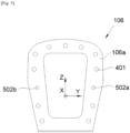
- the spar 106 of the wing 108 has a contact wall 106a which extends in a plane generally perpendicular to the longitudinal direction X.
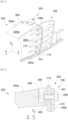
- FIG. 2 shows a first embodiment of an assembly 250 between a spar 106 of the wing 108 and the engine mast 204 and the Figs. 3 and 4 show a second embodiment of an assembly 350 between a spar 106 of the wing 108 and the engine pylon 304.
- the difference between the first embodiment and the second embodiment lies in the shape of the upper spar 204a, 304a of the engine pylon 204, 304 and its attachment to the spar 106 of the wing 108.
- the reactor mast 204, 304a takes the form of a box which here comprises an upper spar 204a, 304a, a lower spar 204b, 304b and two side walls 204c-d, 304c-d.
- the different walls and the spars are integral with each other so as to form a box whose vertical section is generally trapezoidal.
- Each spar 204a-b, 304a-b and each side wall 204c-d, 304c-d extend in a plane generally parallel to the longitudinal direction X, that is to say generally perpendicular to the contact wall 106a.
- the reactor mast 204, 304 is generally symmetrical with respect to a vertical median plane XZ.
- the side walls 204c-d, 304c-d are arranged on either side of the upper spar 204a, 304a.
- the contact wall 106a is pierced with a plurality of first bores 401 where each passes through the contact wall 106a and is parallel to the longitudinal direction X, that is to say perpendicular to the contact wall 106a.
- the reactor mast 204, 304 is arranged at the end of the spar 106 of the wing 108 along the longitudinal direction X, that is to say in the extension of one another along the longitudinal direction X.
- the reactor mast 204, 304 thus extends the spar 106 of the wing 108 in the longitudinal direction X.
- the upper spar 204a, 304a is pierced with a second bore 402 which is also parallel to the longitudinal direction X and aligned with the first bore 401 in the assembled position.
- the second bore is made in an angle iron 210 of the upper spar 204a where the angle iron 210 is parallel to the contact wall 106a.
- the second bore 402 is made from a third bore 308 which is made in the upper spar 304a perpendicular to the longitudinal direction X.
- the second bore 402 thus opens into the third bore 308.
- the third bore 308 opens at an upper face of the upper spar 304a and is preferably blind.
- the side walls 204c-d, 304c-d here comprise angles 212, 312 parallel to the contact wall 106a and also crossed by second bores aligned with first bores of the contact wall 106a parallel to the longitudinal direction X.
- the assembly 250, 350 comprises a nut 206, 406 and a screw 208.
- the screw 208 is screwed into the nut 206, 406 successively through the first bore 401 of the contact wall 106a and the second bore 402 of the upper spar 204a, 304a sandwiching the upper spar 204a, 304a and the contact wall 106a between the head of the screw 208 and the nut 206, 406.
- each screw-nut system works in tension only by taking up the axial forces in the longitudinal direction X, such as the thrust.
- the junction between the engine mast 204, 304 and the spar 106 of the wing 108 is thus made on a single interface plane, the plane of the contact wall 106a where the screw-nut systems are arranged so as to transmit the forces generated by the engine 105 towards the wing 108 while guaranteeing that the junction does not separate.
- the assembly 250, 350 also comprises, arranged symmetrically on either side of the vertical median plane XZ and therefore on each side of the upper spar 204a, 304a, a shear pin 214, 314. There is therefore a shear pin 214, 314 on the port side and one on the starboard side. Each shear pin 214, 314 is also parallel to the longitudinal direction X.
- FIG. 5 shows the spar 106 of the wing 108 and more particularly the contact wall 106a.
- there are eleven screw-nut systems with three at the level of the upper spar 204a, 304a and four for each side wall 204c-d, 304c-d.
- Each shear pin 214, 314 is fitted into a first bore 502a-b of the contact wall 106a, namely a first bore 502a on the port side and a first bore 502b on the starboard side, and a second bore of a side wall 204c-d, 304c-d of the engine pylon 204, 304 here in an angle iron 212, 312 of the side wall 204c-d, 304c-d considered.
- the first bore 502a-b and the associated second bore are aligned in the assembled position.
- the first bores 502a-b and the second bores are arranged on either side of the vertical median plane XZ.
- shear pin 214, 314 fitted into a first bore 502a of the contact wall 106a and a second bore of a side wall 204c-d, 304c-d and another shear pin 214, 314 fitted into a first bore 502b of the contact wall 106a and a second bore of the other side wall 204d-c, 304d-c.
- the shear pins 214, 314 take up the shear forces and the engine torque and they are mounted tightly in the corresponding holes while the screws 208 are mounted with clearance in the corresponding bores, including the intermediate hole and the intermediate bore 410 described below.
- the assembly 250, 350 also comprises an intermediate wall 110 which is disposed between the contact wall 106a and the upper spar 204a, 304a.
- the intermediate wall 110 is crossed by an intermediate bore 410 which the screw 208 passes through.
- nut 406 is a cylindrical nut with a crossed stud (“barrel nut” in English) which is housed in the third bore 308 to lock it in rotation when the screw 208 is tightened.
- the thickness of the upper spar 304a is increased because there is no need to provide space for the angles 210 which makes it possible to optimize the inertia of the reactor mast 304 in order to be able to pass greater forces into the reactor mast 304.
Landscapes
- Engineering & Computer Science (AREA)
- Aviation & Aerospace Engineering (AREA)
- Mechanical Engineering (AREA)
- Connection Of Plates (AREA)
- General Details Of Gearings (AREA)
Applications Claiming Priority (1)
| Application Number | Priority Date | Filing Date | Title |
|---|---|---|---|
| FR2309134A FR3152490A1 (fr) | 2023-08-31 | 2023-08-31 | Assemblage d’un longeron d’aile et d’un mât réacteur alignés horizontalement l’un par rapport à l’autre |
Publications (1)
| Publication Number | Publication Date |
|---|---|
| EP4516668A1 true EP4516668A1 (de) | 2025-03-05 |
Family
ID=88838814
Family Applications (1)
| Application Number | Title | Priority Date | Filing Date |
|---|---|---|---|
| EP24196882.5A Pending EP4516668A1 (de) | 2023-08-31 | 2024-08-28 | Verbindung eines flügelholms und eines horizontal zueinander ausgerichteten reaktormastes |
Country Status (4)
| Country | Link |
|---|---|
| US (1) | US12497181B2 (de) |
| EP (1) | EP4516668A1 (de) |
| CN (1) | CN119527557A (de) |
| FR (1) | FR3152490A1 (de) |
Citations (6)
| Publication number | Priority date | Publication date | Assignee | Title |
|---|---|---|---|---|
| FR2836672A1 (fr) * | 2002-03-04 | 2003-09-05 | Airbus France | Mat d'accrochage d'un moteur sous une voilure d'aeronef |
| FR2891247A1 (fr) * | 2005-09-26 | 2007-03-30 | Airbus France Sas | Ensemble pour aeronef comprenant un element de voilure ainsi qu'un mat d'accrochage |
| US20100314491A1 (en) * | 2007-11-21 | 2010-12-16 | Alistair Forbes | Aircraft engine pylon attachment |
| FR3032421A1 (fr) * | 2015-02-06 | 2016-08-12 | Airbus Operations Sas | Ensemble pour aeronef comprenant une structure primaire de mat d'accrochage integree a la structure de l'element de voilure |
| US10583930B2 (en) * | 2017-06-02 | 2020-03-10 | Spirit Aerosystems, Inc. | Aircraft engine attachment assembly |
| FR3118944A1 (fr) * | 2021-01-20 | 2022-07-22 | Airbus Operations Sas | Structure primaire d’un mât pour la fixation d’un moteur d’aéronef. |
Family Cites Families (1)
| Publication number | Priority date | Publication date | Assignee | Title |
|---|---|---|---|---|
| FR3061148B1 (fr) * | 2016-12-23 | 2022-08-12 | Airbus Operations Sas | Fixation semi-continue d'un mat d'accrochage de moteur a un dispositif de fixation appartenant a la voilure d'un aeronef |
-
2023
- 2023-08-31 FR FR2309134A patent/FR3152490A1/fr not_active Ceased
-
2024
- 2024-08-28 EP EP24196882.5A patent/EP4516668A1/de active Pending
- 2024-08-29 US US18/819,000 patent/US12497181B2/en active Active
- 2024-08-29 CN CN202411197708.0A patent/CN119527557A/zh active Pending
Patent Citations (6)
| Publication number | Priority date | Publication date | Assignee | Title |
|---|---|---|---|---|
| FR2836672A1 (fr) * | 2002-03-04 | 2003-09-05 | Airbus France | Mat d'accrochage d'un moteur sous une voilure d'aeronef |
| FR2891247A1 (fr) * | 2005-09-26 | 2007-03-30 | Airbus France Sas | Ensemble pour aeronef comprenant un element de voilure ainsi qu'un mat d'accrochage |
| US20100314491A1 (en) * | 2007-11-21 | 2010-12-16 | Alistair Forbes | Aircraft engine pylon attachment |
| FR3032421A1 (fr) * | 2015-02-06 | 2016-08-12 | Airbus Operations Sas | Ensemble pour aeronef comprenant une structure primaire de mat d'accrochage integree a la structure de l'element de voilure |
| US10583930B2 (en) * | 2017-06-02 | 2020-03-10 | Spirit Aerosystems, Inc. | Aircraft engine attachment assembly |
| FR3118944A1 (fr) * | 2021-01-20 | 2022-07-22 | Airbus Operations Sas | Structure primaire d’un mât pour la fixation d’un moteur d’aéronef. |
Also Published As
| Publication number | Publication date |
|---|---|
| CN119527557A (zh) | 2025-02-28 |
| FR3152490A1 (fr) | 2025-03-07 |
| US20250074611A1 (en) | 2025-03-06 |
| US12497181B2 (en) | 2025-12-16 |
Similar Documents
| Publication | Publication Date | Title |
|---|---|---|
| FR3068008B1 (fr) | Ensemble de motorisation pour un aeronef | |
| EP3696089B1 (de) | Baugruppe für luftfahrzeug, beinhaltend einen tragflügelpylon, einen flügel und zwei halterungssysteme zur befestigung des tragflügelpylons mit dem flügel | |
| EP2500268A1 (de) | Aufhängesäule eines Flugzeugmotors | |
| EP3521173B1 (de) | Einheit für luftfahrzeug, die eine primärstruktur einer aufhängesäule umfasst, die an einem fahrwerkskasten mithilfe einer verschraubten verbindung befestigt ist | |
| EP3486174B1 (de) | Hintere motorbefestigung für einen luftfahrzeugmotor | |
| EP4484297B1 (de) | Vordermotorbefestigungssystem für einen flugzeugmotor mit kompakter struktur | |
| WO2021104913A1 (fr) | Systeme d'attache moteur avant pour un moteur aéronef qui comporte une structure allégée | |
| EP3505439A1 (de) | Einheit für ein luftfahrzeug, die eine primärstruktur eines aufhängungsmasts umfasst, die an einem flügelkasten durch befestigungselemente befestigt ist und im vorderkantenbereich ein reduziertes volumen aufweist | |
| EP3984888B1 (de) | Einheit für ein luftfahrzeug, die einen pylon und einen flügel umfasst | |
| FR3156756A1 (fr) | Ensemble propulsif pour aéronef comportant un moteur, un mât et des moyens d’accrochage du moteur au mât | |
| FR3121428A1 (fr) | Mât réacteur d’aéronef comportant un ensemble mobile de capots | |
| FR3098794A1 (fr) | Ensemble propulseur d’aéronef comportant une structure primaire de mât et une attache moteur avant améliorées | |
| EP4516668A1 (de) | Verbindung eines flügelholms und eines horizontal zueinander ausgerichteten reaktormastes | |
| EP4516678A1 (de) | Verbindung eines flügelholms und eines horizontal zueinander ausgerichteten reaktormastes | |
| EP1266826A1 (de) | Schubbefestigung eines Triebwerkes an einem Luftfahrzeug | |
| FR3083776A1 (fr) | Mat d'accrochage pour un turboreacteur d'un aeronef comportant une structure particuliere | |
| EP4183690B1 (de) | Triebwerksmast zur kopplung eines strahltriebwerks an einen flügel eines flugzeugs | |
| EP3728039B1 (de) | Aufhängevorrichtung | |
| EP4484298A1 (de) | Vordermotorbefestigungssystem für einen flugzeugmotor mit kompakter struktur | |
| EP3848288B1 (de) | Hintere befestigung zwischen einer aufhängesäule und einer tragfläche eines flugzeugs | |
| EP4450397B1 (de) | Anordnung zur befestigung von balken mit einer trägerplatte und zwei beschlagteilen an beiden seiten der trägerplatte | |
| FR3081830A1 (fr) | Paroi aerodynamique d’aeronef comportant au moins un generateur de tourbillons et aeronef comprenant ladite paroi aerodynamique | |
| EP4442577B1 (de) | Reaktormast zur befestigung eines flugzeugmotors | |
| FR3118944A1 (fr) | Structure primaire d’un mât pour la fixation d’un moteur d’aéronef. | |
| FR3047726A1 (fr) | Mat d'un aeronef |
Legal Events
| Date | Code | Title | Description |
|---|---|---|---|
| PUAI | Public reference made under article 153(3) epc to a published international application that has entered the european phase |
Free format text: ORIGINAL CODE: 0009012 |
|
| STAA | Information on the status of an ep patent application or granted ep patent |
Free format text: STATUS: THE APPLICATION HAS BEEN PUBLISHED |
|
| AK | Designated contracting states |
Kind code of ref document: A1 Designated state(s): AL AT BE BG CH CY CZ DE DK EE ES FI FR GB GR HR HU IE IS IT LI LT LU LV MC ME MK MT NL NO PL PT RO RS SE SI SK SM TR |
|
| STAA | Information on the status of an ep patent application or granted ep patent |
Free format text: STATUS: REQUEST FOR EXAMINATION WAS MADE |
|
| 17P | Request for examination filed |
Effective date: 20250903 |
|
| GRAP | Despatch of communication of intention to grant a patent |
Free format text: ORIGINAL CODE: EPIDOSNIGR1 |
|
| STAA | Information on the status of an ep patent application or granted ep patent |
Free format text: STATUS: GRANT OF PATENT IS INTENDED |