EP4449933A2 - Stollenanordnung - Google Patents
Stollenanordnung Download PDFInfo
- Publication number
- EP4449933A2 EP4449933A2 EP24198283.4A EP24198283A EP4449933A2 EP 4449933 A2 EP4449933 A2 EP 4449933A2 EP 24198283 A EP24198283 A EP 24198283A EP 4449933 A2 EP4449933 A2 EP 4449933A2
- Authority
- EP
- European Patent Office
- Prior art keywords
- cleat
- biasing member
- cleat assembly
- anchor
- assembly
- Prior art date
- Legal status (The legal status is an assumption and is not a legal conclusion. Google has not performed a legal analysis and makes no representation as to the accuracy of the status listed.)
- Pending
Links
Images


Classifications
-
- A—HUMAN NECESSITIES
- A43—FOOTWEAR
- A43C—FASTENINGS OR ATTACHMENTS OF FOOTWEAR; LACES IN GENERAL
- A43C15/00—Non-skid devices or attachments
- A43C15/16—Studs or cleats for football or like boots
- A43C15/161—Studs or cleats for football or like boots characterised by the attachment to the sole
-
- A—HUMAN NECESSITIES
- A43—FOOTWEAR
- A43C—FASTENINGS OR ATTACHMENTS OF FOOTWEAR; LACES IN GENERAL
- A43C15/00—Non-skid devices or attachments
- A43C15/16—Studs or cleats for football or like boots
- A43C15/162—Studs or cleats for football or like boots characterised by the shape
- A43C15/164—Studs or cleats for football or like boots characterised by the shape having a circular cross section
- A43C15/167—Studs or cleats for football or like boots characterised by the shape having a circular cross section frusto-conical or cylindrical
-
- A—HUMAN NECESSITIES
- A43—FOOTWEAR
- A43C—FASTENINGS OR ATTACHMENTS OF FOOTWEAR; LACES IN GENERAL
- A43C15/00—Non-skid devices or attachments
- A43C15/16—Studs or cleats for football or like boots
- A43C15/168—Studs or cleats for football or like boots with resilient means, e.g. shock absorbing means
Definitions
- the exemplary embodiments of present invention relate generally to a cleat assembly for a shoe and, more specifically, to a cleat assembly having multiple biasing members to permit movement of the cleat about multiple degrees of freedom.
- Shoe cleat assemblies that permit axial movement of the cleat with respect to the shoe are known. Such assemblies enable the cleat to move along a longitudinal axis of the cleat. However, such assemblies are limited to only movement along a single degree of freedom.
- a cleat assembly for a shoe comprising an anchor for anchoring to the shoe, a cleat, a first biasing member circumscribing the anchor and engaged with the cleat, and a second biasing member biasing the first biasing member.
- the anchor comprises a main body, a fastener extending from a proximal end of the main body, and a substantially planar bottom about a distal end of the main body, wherein the substantially planar bottom extends radially outwardly from the main body.
- the substantially planar bottom is completely housed within the cleat.
- the cleat circumscribes the anchor, the first biasing member, and the second biasing member.
- the cleat includes an inner race for receiving the first biasing member.
- the first biasing member is press-fittingly engaged with the inner race.
- the cleat assembly further comprises a bushing circumscribing the anchor.
- the bushing slidingly engages the anchor.
- the first biasing member circumscribes the bushing.
- the first biasing member is connected to the bushing.
- the first biasing member is an annular biasing member. According to an aspect, the first biasing member is completely housed within the cleat. According to an aspect, the first biasing member has a bending stiffness coefficient of about 0.08 N ⁇ m/deg to 0.15 N ⁇ m/deg. According to an aspect, the first biasing member provides a bending force independent of the second biasing member providing a biasing force along an axial direction of the anchor.
- the second biasing member directly engages the first biasing member.
- the second biasing member directly engages the bushing.
- the second biasing member circumscribes the anchor.
- the second biasing member has a spring constant from about 99997 N/m to 200170 N/m.
- the anchor, the first biasing member, and the second biasing member are housed within the cleat.
- the cleat assembly further comprises a shroud extending from the cleat.
- the cleat assembly further comprises a deformable member between the cleat and a fastener of the anchor for preventing or expelling debris away from the cleat assembly.
- the deformable member is a shroud, an expandable elastomer, a bellows, and/or a seal.
- a shoe having a sole and a cleat assembly secured to the sole.
- the cleat assembly comprises an anchor for anchoring to the shoe, a cleat, a first biasing member circumscribing the anchor and engaged with the cleat, and a second biasing member biasing the first biasing member.
- the anchor comprises a retaining post, and a fastener pivotably connected to a proximal end of the retaining post.
- the fastener is connected to the retaining post via a ball and socket joint.
- the first biasing member circumscribes the fastener.
- the retaining post includes an annular flange. According to an aspect, the retaining post includes a post and the second biasing member circumscribes the post. According to an aspect, the second biasing member is completely housed within the cleat. According to an aspect, the cleat includes an inner race for receiving a detent on the retaining post.
- the anchor comprises a retaining post and a fastener pivotably connected to a proximal end of the retaining post.
- the fastener is connected to the retaining post via a ball and socket joint.
- the first biasing member circumscribes the fastener.
- the second biasing member is completely housed within the cleat.
- the retaining post includes an annular flange and a post, wherein the second biasing member circumscribes the post.
- the cleat includes an inner race for receiving a detent on the retaining post.
- the cleat assembly provides effective axial shock absorbance coupled with cleat rotatability and 360° tilting of the cleat for enhancing a user's ability to suddenly and easily change direction when wearing a shoe equipped with the cleat assembly, thereby minimizing stress and impact on muscles, joints and ligaments and enhancing the performance of athletes wearing such shoes.
- the cleat assembly enhances rotational or translational release to minimize the occurrence of soft tissue (e.g., ACL or meniscus tears) injuries. It is well known that approximately 50% of individuals with soft tissue injuries will go on to develop osteoarthritis.
- range format is merely for convenience and brevity and should not be construed as an inflexible limitation on the scope of the subject disclosure. Accordingly, the description of a range should be considered to have specifically disclosed all the possible subranges as well as individual numerical values within that range. For example, description of a range such as from 1 to 6 should be considered to have specifically disclosed subranges such as from 1 to 3, from 1 to 4, from 1 to 5, from 2 to 4, from 2 to 6, from 3 to 6 etc., as well as individual numbers within that range, for example, 1, 2, 2.7, 3, 4, 5, 5.3, and 6. This applies regardless of the breadth of the range.
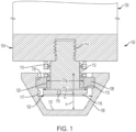
- FIG. 1 illustrates a cleat assembly 100 in accordance with an exemplary embodiment of the present disclosure.
- the cleat assembly 100 includes an anchor 102 for anchoring to a sole 104 of a shoe 105, a cleat 106, a first biasing member 108, and a second biasing member 110. While FIG. 1 depicts a single cleat assembly secured to the sole of a shoe, it is understood that a plurality of such cleat assemblies may be secured to the shoe sole.
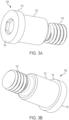
- the anchor 102 is configured as best shown in FIGS. 1 , 3A and 3B .
- the anchor includes a main body 112, a fastener 114 extending from a proximal end of the main body, and a substantially planar bottom 116 about a distal end of the main body.
- the substantially planar bottom extends radially outwardly from the main body 112 to define a flange 115.
- the substantially planar bottom is completely housed within the cleat 106.
- the fastener 114 extends proximally from the main body.
- the main body 112 of the anchor 102 is cylindrical in shape (and can be of a longitudinal cross-section of other shapes, e.g.
- the fastener 114 is smaller in diameter than the main body.
- the main body has a length substantially the same or slightly smaller than a longitudinal length of the cleat.
- the fastener is a threaded fastener e.g., for threadedly engaging corresponding threads provided in the sole 104 of the shoe.
- the main body 112 can have a recess 119 adapted for receiving a tool such as a wrench or the like for turning the fastener into and out of the sole of the shoe. While the present exemplary embodiment of the fastener is threaded, other types of fasteners applicable for the intended purpose are permitted, e.g., J-lock or friction-fit fasteners, and the like.
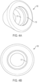
- the cleat 106 is configured as best shown in FIGS. 1 , 4A and 4B .
- the cleat is shaped substantially as a frustoconical cone having a substantially hollow interior.
- the interior of the cleat includes a cylindrical side wall 117.
- the cleat includes an inner race 118 within the cylindrical side wall 117 for receiving the first biasing member.
- the cleat has an inner diameter "ID”, e.g., defined by the cylindrical side wall 117, larger than a maximum outer diameter "ODa,” of the substantially planar bottom of the anchor 102.
- the cleat has a hollow interior having a height "h".
- the height of the hollow interior has sufficient clearance to permit the top of the cleat 106 to mate with the shoe sole 104 as a bushing 120, described below, slides upwardly along the main body 112 of the anchor and compresses the second biasing member 110.
- the cleat assembly further comprises the bushing 120, as best shown in FIG. 1 .
- the bushing is preferably configured as an annular bushing and may be made e.g., from a metal, a rigid plastic, or the like.
- the bushing may alternatively include bearings to facilitate rotational engagement with the anchor 102.
- the bushing 120 circumscribes the anchor 102 and is slidingly engaged with the anchor. That is, the bushing has the same or a slightly larger diameter than the main body 112 of the anchor 102 whereby the busing is capable of sliding along a longitudinal length of the anchor.
- the bushing 120 has a maximum outer diameter "OD B " that is less than the maximum outer diameter "ODa," of the substantially planar bottom of anchor 102.
- the first biasing member 108 circumscribes the bushing 120 and is engaged with the cleat.
- the first biasing member can be press-fittingly engaged with the inner race 118 to securely position the first biasing member with respect to the cleat.
- the first biasing member can be connected to the bushing via a friction fit, adhesives or other suitable connector mechanisms.
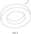
- the first biasing member is an annular biasing member.
- the first biasing member can be formed from, e.g., an elastomer or other resilient material, and have a bending stiffness coefficient of about 0.08 N ⁇ m/deg to 0.15 N ⁇ m/deg, including 0.06, 0.07, 0.09, 0.10, 0.11, 0.12, 0.13, 0.14, 0.16, 0.17 N ⁇ m/deg.
- the first biasing member is completely housed within the cleat 106.
- the first biasing member provides a bending force independent of the second biasing member 110 providing a biasing force along an axial direction of the anchor 102. This torque versus angle relationship may be linear or non-linear.
- the second biasing member 110 engages the first biasing member 108 and/or the bushing 120 and, more particularly, directly engages the first biasing member and/or bushing.
- the second biasing member circumscribes the anchor 102 e.g., about its main body 112.
- the second biasing member can be a spring, or appropriately configured elastomer, polymeric member, or a linear biasing member, or a non-linear biasing member.
- the second biasing member has a spring constant from about 99,997 N/m to 200,170 N/m, including 83,185; 87,563; 91,941; 96,320; 100,698; 105,076; 109,454; 113,832; 118,211; 122,589; 126,967; 131,345; 135,723; 140,101; 144,480; 148,858; 153,236; 157,614; 161,992; 166,370; 170,749; 175,127; 179,505; 183,883; 188,261; 192,640; 197,018; 201,396; 205,774; 210,152; 214,530; 218,909; 223,287; and 227,665 N/m.
- the cleat 106 circumscribes the anchor 102, the first biasing member 108, and the second biasing member 110.
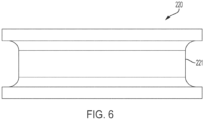
- cleat assembly 200 constructed in accordance with another exemplary embodiment of the subject disclosure.
- Cleat assembly 200 is constructed similar to cleat assembly 100. Accordingly, only those aspects of the cleat assembly 200 that depart materially in structure and/or function from their counterparts in cleat assembly 100, or are otherwise necessary for a proper understanding of the subject disclosure, will be discussed in detail.
- the bushing 220 has a maximum outer diameter OD B that is greater than the maximum outer diameter OD A of the anchor 202, such as the substantially planar bottom.
- the bushing 220 includes an inner race 221.
- the inner race faces opposite the inner race 218 of the cleat 206 ( FIG. 2 ).
- the inner races 218 and 221 serve to retain the first biasing member 208 in the cleat 206.
- the first biasing member can be press-fittingly engaged with the first and second races 218, 221 and/or attached via adhesive, welding and the like.
- the second biasing member 210 engages the bushing 220 and the second biasing member and, more particularly, directly engages the bushing 220.
- the second biasing member 110, 210 is illustrated as a compression spring.
- the second biasing member 110, 210 is a wave spring, although as noted above it may assume other forms including, without limitation, an elastomer, a polymeric member, a linear biasing member, or a non-linear biasing member, which may be annular in shape or non-annular, e.g., linear, square, hexagonal, and the like.
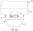
- cleat assembly 300 constructed in accordance with another exemplary embodiment of the subject disclosure.
- Cleat assembly 300 is constructed similar to cleat assemblies 100 and 200. Accordingly, only those aspects of the cleat assembly 300 that depart materially in structure and/or function from their counterparts in cleat assemblies 100 and 200, or are otherwise necessary for a proper understanding of the subject disclosure, will be discussed in detail.
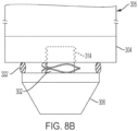
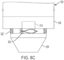
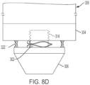
- Cleat assembly 300 comprises a deformable member between the cleat 306 and a fastener 314 of the anchor 302 for preventing or expelling debris away from the cleat assembly such as the area between the cleat and the shoe.
- the deformable member can be a shroud 322 ( FIG. 8A ), an expandable elastomer 322' ( FIG. 8B ), a bellows 322" ( FIG. 8C ) and/or a seal 322′′′ ( FIG. 8D ) that e.g. circumscribes or completely circumscribes the cleat and extends from the cleat.
- the deformable member comprises an annular shroud extending from the cleat 306.
- FIGS. 9 and 10 there is shown a cleat assembly 900 constructed in accordance with another exemplary embodiment of the subject disclosure.
- the cleat assembly 900 includes an anchor 902 for anchoring to a sole 904 of a shoe 905, a cleat 906, a first biasing member 908, and a second biasing member 910. While FIGS. 9 and 10 depict a single cleat assembly secured to the sole of a shoe, it is understood that a plurality of such cleat assemblies may be secured to the shoe sole.
- the anchor 902 comprises a retaining post 924 and a fastener 926 pivotably connected to a proximal end of the retaining post.
- the fastener 926 is connected to the retaining post 924 via a ball and socket joint 928 seated in a recess 930 provided in a proximal end of the retaining post.
- the ball and socket joint securely connects the retaining post to the fastener.
- the retaining post includes an annular flange 932 constructed and arranged to contact the first biasing member 908, as described in greater detail below.
- the annular flange has an outer periphery substantially corresponding in size and shape to an outer periphery of the first biasing member.
- the retaining post At its distal end, the retaining post includes a post 934.
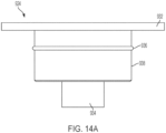
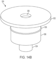
- the retaining post further includes a detent 936 ( FIGS. 9 , 10 , 14A and 14B ) in the form of an annular bead formed on a circumferential wall 938 of the retaining post.
- the cleat 906 includes an inner race 939 for receiving the detent 936 on the retaining post 924.
- the inner race is sized sufficiently to allow axial movement of the cleat relative to the retaining post e.g., to allow the detent 936 to move in a longitudinal axial direction of the cleat.
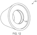
- the fastener 926 is best shown in FIGS. 11A and 11B .
- the fastener 926 includes external threading 940 for threadedly engaging corresponding threading 942 ( FIGS. 9 and 10 ) provided in the shoe sole 904.
- the fastener may be provided with a socket 944 that may be engaged by a suitable unillustrated tool such as a wrench or the like for securely fastening the fastener to the shoe sole.
- a suitable unillustrated tool such as a wrench or the like for securely fastening the fastener to the shoe sole.
- the fastener 926 is threaded, other types of fasteners applicable for the intended use are permitted, e.g., J-lock or friction-fit fasteners and the like.
- the fastener 926 carries the ball and socket joint 928 at its distal end.
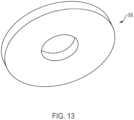
- FIGS. 9 and 10 further show that the first biasing member 908 circumscribes the fastener 926.
- the first biasing member can be connected to the annular flange 932 of the retaining post 924 or to the sole 904 of the shoe 905, e.g., by adhesives or other suitable connector mechanisms.
- the first biasing member is an annular biasing member.
- the first biasing member can be formed from, e.g., an elastomer or other suitable resilient material, and have a bending stiffness coefficient of about 0.08 N ⁇ m/deg to 0.15 N ⁇ m/deg, including 0.06, 0.07, 0.09, 0.10, 0.11, 0.12, 0.13, 0.14, 0.16, and 0.17 N ⁇ m/deg.
- This torque versus angle relationship may be linear or non-linear.
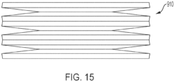
- the second biasing member 910 circumscribes the post 934 of the retaining post 924 and is completely housed within the cleat 906.
- the second biasing member can be constructed as an accordion-like compression spring.
- the second biasing member may assume other forms including, without limitation, an elastomer, a polymeric member, a linear biasing member, or a non-linear biasing member, which may be annular in shape or non-annular, e.g., linear, square, hexagonal, and the like.
- the second biasing member 910 has a spring constant from about 28,020 N/m to 43,785 N/m, including 24,518; 25,393; 26,269; 27,145; 28,020; 28,896; 29,772; 30,647; 31,523; 32,398; 33,274; 34,150; 35,025; 35,901; 36,777; 37,652; 38,528; 39,404; 40,279; 41,155; 42,030; 42,906; 44,657; 45,533; 46,409; 47,284; and 48,160 N/m.
- FIG. 10 shows the cleat of the cleat assembly in a deflected state such as when a user is in the midst of a change in direction while running. In this state, the first biasing member 908 is compressed or biased along a side thereof by the retaining post 924 and the flange 932.
- the first biasing member exerts a bending biasing force against the retaining post 924 and the flange 932 which operates to return the cleat to the undeflected state when the user ceases to exert deflecting force against the cleat.
Landscapes
- Footwear And Its Accessory, Manufacturing Method And Apparatuses (AREA)
- Bolts, Nuts, And Washers (AREA)
Applications Claiming Priority (3)
| Application Number | Priority Date | Filing Date | Title |
|---|---|---|---|
| US201962815819P | 2019-03-08 | 2019-03-08 | |
| PCT/US2020/021501 WO2020185599A1 (en) | 2019-03-08 | 2020-03-06 | Cleat assembly |
| EP20714096.3A EP3920749B1 (de) | 2019-03-08 | 2020-03-06 | Stollenanordnung |
Related Parent Applications (2)
| Application Number | Title | Priority Date | Filing Date |
|---|---|---|---|
| EP20714096.3A Division EP3920749B1 (de) | 2019-03-08 | 2020-03-06 | Stollenanordnung |
| EP20714096.3A Division-Into EP3920749B1 (de) | 2019-03-08 | 2020-03-06 | Stollenanordnung |
Publications (2)
| Publication Number | Publication Date |
|---|---|
| EP4449933A2 true EP4449933A2 (de) | 2024-10-23 |
| EP4449933A3 EP4449933A3 (de) | 2024-12-25 |
Family
ID=72336583
Family Applications (2)
| Application Number | Title | Priority Date | Filing Date |
|---|---|---|---|
| EP20714096.3A Active EP3920749B1 (de) | 2019-03-08 | 2020-03-06 | Stollenanordnung |
| EP24198283.4A Pending EP4449933A3 (de) | 2019-03-08 | 2020-03-06 | Stollenanordnung |
Family Applications Before (1)
| Application Number | Title | Priority Date | Filing Date |
|---|---|---|---|
| EP20714096.3A Active EP3920749B1 (de) | 2019-03-08 | 2020-03-06 | Stollenanordnung |
Country Status (5)
| Country | Link |
|---|---|
| US (3) | US11213101B2 (de) |
| EP (2) | EP3920749B1 (de) |
| JP (1) | JP7377279B2 (de) |
| ES (1) | ES3019387T3 (de) |
| WO (1) | WO2020185599A1 (de) |
Families Citing this family (2)
| Publication number | Priority date | Publication date | Assignee | Title |
|---|---|---|---|---|
| EP3920749B1 (de) * | 2019-03-08 | 2025-03-05 | New York Society for the Relief of the Ruptured and Crippled, maintaining the Hospital for Special Surgery | Stollenanordnung |
| WO2023141152A1 (en) | 2022-01-19 | 2023-07-27 | Jalmrr, Llc | Deflectable cleat system for footwear |
Family Cites Families (26)
| Publication number | Priority date | Publication date | Assignee | Title |
|---|---|---|---|---|
| US2911738A (en) * | 1958-08-27 | 1959-11-10 | John A Clerke | Athletic shoe cleat |
| US4146979A (en) * | 1977-10-25 | 1979-04-03 | Fabbrie Gilbert R | Self-cleaning golf-shoe cleat |
| DE3046811A1 (de) | 1980-12-12 | 1982-07-29 | Puma-Sportschuhfabriken Rudolf Dassler Kg, 8522 Herzogenaurach | Laufsohle aus kunststoff fuer sportschuhe, insbesondere rennschuhe |
| DE3148038C2 (de) * | 1981-12-04 | 1985-10-31 | adidas Sportschuhfabriken Adi Dassler Stiftung & Co KG, 8522 Herzogenaurach | Sportschuh, insbesondere Fußballschuh |
| JPS59141901A (ja) * | 1983-02-01 | 1984-08-14 | 広木 敏雄 | はきもののスベリ止装置 |
| WO1987007119A1 (en) | 1986-05-27 | 1987-12-03 | Feldstein Frank I | Retractable bicycle shoe cleat |
| US4873774A (en) | 1988-03-01 | 1989-10-17 | Universal Plastics Incorporated | Shoe sole with retractable cleats |
| US5617653A (en) | 1991-04-15 | 1997-04-08 | Andrew S. Walker | Break-away cleat assembly for athletic shoe |
| DE9214782U1 (de) * | 1992-10-31 | 1994-03-03 | Puma Ag Rudolf Dassler Sport, 91074 Herzogenaurach | Sportschuh mit einer Laufsohle mit Halterungseinsätzen zur Halterung von Greifelementen |
| JPH0716443B2 (ja) * | 1993-02-18 | 1995-03-01 | 美津濃株式会社 | スパイク取付装置 |
| US5377431A (en) * | 1993-06-15 | 1995-01-03 | Walker; Andrew S. | Directionally yieldable cleat assembly |
| JPH08294404A (ja) * | 1995-02-15 | 1996-11-12 | Tatekawa Spring Seisakusho:Kk | スパイクシューズのスパイクユニット |
| AU6910796A (en) | 1996-01-11 | 1997-08-01 | John E. Fitzgerald | Retractable golf shoe cleat |
| JPH10201502A (ja) * | 1997-01-20 | 1998-08-04 | Maruman Golf Corp | スポーツシューズ |
| EP1253835A1 (de) | 2000-02-07 | 2002-11-06 | Ahcene Kheloufi | Punktdruckdämpfungselement mit direktem oder indirektem bodenkontakt für sportschuhsohlen |
| US6442872B1 (en) * | 2001-03-23 | 2002-09-03 | Canon Liao | Shoe spike assembly having cushioning device |
| US6647647B2 (en) * | 2001-11-20 | 2003-11-18 | Nike, Inc. | Article of footwear with a ground-engaging member and method of altering a ground-engaging member |
| DE20208347U1 (de) | 2002-05-28 | 2002-10-10 | Weidinger, Thomas, 74736 Hardheim | Schuhsohle mit zumindest einem längenveränderbaren Stollen |
| GB2392604B (en) | 2002-08-21 | 2004-08-11 | Michael Anthony Kenneth Bell | Improvements to and relating to studded footwear |
| US7430819B2 (en) | 2004-12-22 | 2008-10-07 | Nike, Inc. | Article of footwear with height adjustable cleat-member |
| DE202007006860U1 (de) | 2007-05-10 | 2008-09-18 | Weidinger, Thomas | Laufschuh mit zumindest einem Stollen |
| IT1394301B1 (it) | 2009-05-20 | 2012-06-06 | Campari | Calzatura sportiva, particolarmente per uso calcistico e simili. |
| ITMI20112089A1 (it) | 2011-11-17 | 2013-05-18 | Enrico Campari | Calzatura sportiva, particolarmente per uso calcistico e simili. |
| US9717306B2 (en) * | 2014-07-23 | 2017-08-01 | Hernan Sanchez | Cleat assembly for an athletic shoe and an athletic shoe comprising same |
| WO2020153511A1 (ko) | 2019-01-23 | 2020-07-30 | 신원화성(주) | 충격흡수 및 미끄럼방지 신발 |
| EP3920749B1 (de) * | 2019-03-08 | 2025-03-05 | New York Society for the Relief of the Ruptured and Crippled, maintaining the Hospital for Special Surgery | Stollenanordnung |
-
2020
- 2020-03-06 EP EP20714096.3A patent/EP3920749B1/de active Active
- 2020-03-06 US US16/811,847 patent/US11213101B2/en active Active
- 2020-03-06 EP EP24198283.4A patent/EP4449933A3/de active Pending
- 2020-03-06 JP JP2021552727A patent/JP7377279B2/ja active Active
- 2020-03-06 ES ES20714096T patent/ES3019387T3/es active Active
- 2020-03-06 WO PCT/US2020/021501 patent/WO2020185599A1/en not_active Ceased
-
2021
- 2021-12-02 US US17/457,293 patent/US11980255B2/en active Active
-
2024
- 2024-02-22 US US18/584,515 patent/US12490812B2/en active Active
Also Published As
| Publication number | Publication date |
|---|---|
| JP7377279B2 (ja) | 2023-11-09 |
| US20240188687A1 (en) | 2024-06-13 |
| ES3019387T3 (en) | 2025-05-20 |
| EP3920749C0 (de) | 2025-03-05 |
| US12490812B2 (en) | 2025-12-09 |
| US11213101B2 (en) | 2022-01-04 |
| WO2020185599A1 (en) | 2020-09-17 |
| US11980255B2 (en) | 2024-05-14 |
| JP2022524010A (ja) | 2022-04-27 |
| US20200281323A1 (en) | 2020-09-10 |
| EP3920749A1 (de) | 2021-12-15 |
| EP3920749B1 (de) | 2025-03-05 |
| EP4449933A3 (de) | 2024-12-25 |
| US20220087369A1 (en) | 2022-03-24 |
Similar Documents
| Publication | Publication Date | Title |
|---|---|---|
| US20240188687A1 (en) | Cleat assembly | |
| US10774860B2 (en) | Treatment element attachment system | |
| US20170282029A1 (en) | Golf club having removeable weight | |
| US4372621A (en) | Ball and socket joints | |
| EP3654903B1 (de) | Befestigungssystem für mehrere behandlungselemente | |
| EP2845501A1 (de) | Schuh | |
| US10231520B2 (en) | Walker glide | |
| US20260047644A1 (en) | Cleat assembly | |
| JP2002013546A5 (de) | ||
| US5377441A (en) | Rod clamp | |
| CA2973935C (en) | Pole having a tip spring mechanism | |
| US6085612A (en) | Elastomer detent assembly | |
| US10232777B2 (en) | Mirror adjustment mechanism, in particular for a wing mirror for a motor vehicle | |
| JP2004360817A (ja) | 等速ジョイント用ブーツ | |
| US20140179449A1 (en) | Crimpless boot | |
| US20190022838A1 (en) | Bearing race and seal driver handle | |
| JPH0229321B2 (ja) | Suberidomegu | |
| US20200338405A1 (en) | Golf club | |
| US20260002563A1 (en) | Ball joint assembly | |
| JP2003329058A (ja) | 接続キャップ | |
| JP2598534Y2 (ja) | 等速ジョイント用ブーツ | |
| WO2018130749A1 (en) | Facial muscle trainer | |
| KR200333133Y1 (ko) | 회전운동 능력을 구비한 운동화 | |
| US20200367601A1 (en) | Separate protection component | |
| JP2000166614A (ja) | スパイク用弾性アダプタ |
Legal Events
| Date | Code | Title | Description |
|---|---|---|---|
| PUAI | Public reference made under article 153(3) epc to a published international application that has entered the european phase |
Free format text: ORIGINAL CODE: 0009012 |
|
| STAA | Information on the status of an ep patent application or granted ep patent |
Free format text: STATUS: THE APPLICATION HAS BEEN PUBLISHED |
|
| AC | Divisional application: reference to earlier application |
Ref document number: 3920749 Country of ref document: EP Kind code of ref document: P |
|
| AK | Designated contracting states |
Kind code of ref document: A2 Designated state(s): AL AT BE BG CH CY CZ DE DK EE ES FI FR GB GR HR HU IE IS IT LI LT LU LV MC MK MT NL NO PL PT RO RS SE SI SK SM TR |
|
| PUAL | Search report despatched |
Free format text: ORIGINAL CODE: 0009013 |
|
| AK | Designated contracting states |
Kind code of ref document: A3 Designated state(s): AL AT BE BG CH CY CZ DE DK EE ES FI FR GB GR HR HU IE IS IT LI LT LU LV MC MK MT NL NO PL PT RO RS SE SI SK SM TR |
|
| RIC1 | Information provided on ipc code assigned before grant |
Ipc: A43C 15/16 20060101AFI20241118BHEP |
|
| RAP3 | Party data changed (applicant data changed or rights of an application transferred) |
Owner name: NEW YORK SOCIETY FOR THE RELIEF OF THE RUPTUREDAND CRIPPLED, MAINTAINING THE HOSPITAL FORSPECIAL SURGERY |
|
| STAA | Information on the status of an ep patent application or granted ep patent |
Free format text: STATUS: REQUEST FOR EXAMINATION WAS MADE |
|
| 17P | Request for examination filed |
Effective date: 20250624 |