EP4448256B1 - Hybridverbund - Google Patents
Hybridverbund Download PDFInfo
- Publication number
- EP4448256B1 EP4448256B1 EP22826186.3A EP22826186A EP4448256B1 EP 4448256 B1 EP4448256 B1 EP 4448256B1 EP 22826186 A EP22826186 A EP 22826186A EP 4448256 B1 EP4448256 B1 EP 4448256B1
- Authority
- EP
- European Patent Office
- Prior art keywords
- component
- joint
- joint surface
- adhesive
- hbf
- Prior art date
- Legal status (The legal status is an assumption and is not a legal conclusion. Google has not performed a legal analysis and makes no representation as to the accuracy of the status listed.)
- Active
Links
Images


Classifications
-
- B—PERFORMING OPERATIONS; TRANSPORTING
- B29—WORKING OF PLASTICS; WORKING OF SUBSTANCES IN A PLASTIC STATE IN GENERAL
- B29C—SHAPING OR JOINING OF PLASTICS; SHAPING OF MATERIAL IN A PLASTIC STATE, NOT OTHERWISE PROVIDED FOR; AFTER-TREATMENT OF THE SHAPED PRODUCTS, e.g. REPAIRING
- B29C66/00—General aspects of processes or apparatus for joining preformed parts
- B29C66/01—General aspects dealing with the joint area or with the area to be joined
- B29C66/05—Particular design of joint configurations
- B29C66/10—Particular design of joint configurations particular design of the joint cross-sections
- B29C66/11—Joint cross-sections comprising a single joint-segment, i.e. one of the parts to be joined comprising a single joint-segment in the joint cross-section
- B29C66/112—Single lapped joints
- B29C66/1122—Single lap to lap joints, i.e. overlap joints
-
- B—PERFORMING OPERATIONS; TRANSPORTING
- B29—WORKING OF PLASTICS; WORKING OF SUBSTANCES IN A PLASTIC STATE IN GENERAL
- B29C—SHAPING OR JOINING OF PLASTICS; SHAPING OF MATERIAL IN A PLASTIC STATE, NOT OTHERWISE PROVIDED FOR; AFTER-TREATMENT OF THE SHAPED PRODUCTS, e.g. REPAIRING
- B29C65/00—Joining or sealing of preformed parts, e.g. welding of plastics materials; Apparatus therefor
- B29C65/48—Joining or sealing of preformed parts, e.g. welding of plastics materials; Apparatus therefor using adhesives, i.e. using supplementary joining material; solvent bonding
- B29C65/4805—Joining or sealing of preformed parts, e.g. welding of plastics materials; Apparatus therefor using adhesives, i.e. using supplementary joining material; solvent bonding characterised by the type of adhesives
- B29C65/481—Non-reactive adhesives, e.g. physically hardening adhesives
- B29C65/4815—Hot melt adhesives, e.g. thermoplastic adhesives
-
- B—PERFORMING OPERATIONS; TRANSPORTING
- B29—WORKING OF PLASTICS; WORKING OF SUBSTANCES IN A PLASTIC STATE IN GENERAL
- B29C—SHAPING OR JOINING OF PLASTICS; SHAPING OF MATERIAL IN A PLASTIC STATE, NOT OTHERWISE PROVIDED FOR; AFTER-TREATMENT OF THE SHAPED PRODUCTS, e.g. REPAIRING
- B29C65/00—Joining or sealing of preformed parts, e.g. welding of plastics materials; Apparatus therefor
- B29C65/48—Joining or sealing of preformed parts, e.g. welding of plastics materials; Apparatus therefor using adhesives, i.e. using supplementary joining material; solvent bonding
- B29C65/4805—Joining or sealing of preformed parts, e.g. welding of plastics materials; Apparatus therefor using adhesives, i.e. using supplementary joining material; solvent bonding characterised by the type of adhesives
- B29C65/483—Reactive adhesives, e.g. chemically curing adhesives
-
- B—PERFORMING OPERATIONS; TRANSPORTING
- B29—WORKING OF PLASTICS; WORKING OF SUBSTANCES IN A PLASTIC STATE IN GENERAL
- B29C—SHAPING OR JOINING OF PLASTICS; SHAPING OF MATERIAL IN A PLASTIC STATE, NOT OTHERWISE PROVIDED FOR; AFTER-TREATMENT OF THE SHAPED PRODUCTS, e.g. REPAIRING
- B29C65/00—Joining or sealing of preformed parts, e.g. welding of plastics materials; Apparatus therefor
- B29C65/48—Joining or sealing of preformed parts, e.g. welding of plastics materials; Apparatus therefor using adhesives, i.e. using supplementary joining material; solvent bonding
- B29C65/50—Joining or sealing of preformed parts, e.g. welding of plastics materials; Apparatus therefor using adhesives, i.e. using supplementary joining material; solvent bonding using adhesive tape, e.g. thermoplastic tape; using threads or the like
- B29C65/5057—Joining or sealing of preformed parts, e.g. welding of plastics materials; Apparatus therefor using adhesives, i.e. using supplementary joining material; solvent bonding using adhesive tape, e.g. thermoplastic tape; using threads or the like positioned between the surfaces to be joined
-
- B—PERFORMING OPERATIONS; TRANSPORTING
- B29—WORKING OF PLASTICS; WORKING OF SUBSTANCES IN A PLASTIC STATE IN GENERAL
- B29C—SHAPING OR JOINING OF PLASTICS; SHAPING OF MATERIAL IN A PLASTIC STATE, NOT OTHERWISE PROVIDED FOR; AFTER-TREATMENT OF THE SHAPED PRODUCTS, e.g. REPAIRING
- B29C65/00—Joining or sealing of preformed parts, e.g. welding of plastics materials; Apparatus therefor
- B29C65/56—Joining or sealing of preformed parts, e.g. welding of plastics materials; Apparatus therefor using mechanical means or mechanical connections, e.g. form-fits
- B29C65/562—Joining or sealing of preformed parts, e.g. welding of plastics materials; Apparatus therefor using mechanical means or mechanical connections, e.g. form-fits using extra joining elements, i.e. which are not integral with the parts to be joined
- B29C65/564—Joining or sealing of preformed parts, e.g. welding of plastics materials; Apparatus therefor using mechanical means or mechanical connections, e.g. form-fits using extra joining elements, i.e. which are not integral with the parts to be joined hidden in the joint, e.g. dowels or Z-pins
-
- B—PERFORMING OPERATIONS; TRANSPORTING
- B29—WORKING OF PLASTICS; WORKING OF SUBSTANCES IN A PLASTIC STATE IN GENERAL
- B29C—SHAPING OR JOINING OF PLASTICS; SHAPING OF MATERIAL IN A PLASTIC STATE, NOT OTHERWISE PROVIDED FOR; AFTER-TREATMENT OF THE SHAPED PRODUCTS, e.g. REPAIRING
- B29C65/00—Joining or sealing of preformed parts, e.g. welding of plastics materials; Apparatus therefor
- B29C65/56—Joining or sealing of preformed parts, e.g. welding of plastics materials; Apparatus therefor using mechanical means or mechanical connections, e.g. form-fits
- B29C65/64—Joining a non-plastics element to a plastics element, e.g. by force
-
- B—PERFORMING OPERATIONS; TRANSPORTING
- B29—WORKING OF PLASTICS; WORKING OF SUBSTANCES IN A PLASTIC STATE IN GENERAL
- B29C—SHAPING OR JOINING OF PLASTICS; SHAPING OF MATERIAL IN A PLASTIC STATE, NOT OTHERWISE PROVIDED FOR; AFTER-TREATMENT OF THE SHAPED PRODUCTS, e.g. REPAIRING
- B29C65/00—Joining or sealing of preformed parts, e.g. welding of plastics materials; Apparatus therefor
- B29C65/72—Joining or sealing of preformed parts, e.g. welding of plastics materials; Apparatus therefor by combined operations or combined techniques, e.g. welding and stitching
-
- B—PERFORMING OPERATIONS; TRANSPORTING
- B29—WORKING OF PLASTICS; WORKING OF SUBSTANCES IN A PLASTIC STATE IN GENERAL
- B29C—SHAPING OR JOINING OF PLASTICS; SHAPING OF MATERIAL IN A PLASTIC STATE, NOT OTHERWISE PROVIDED FOR; AFTER-TREATMENT OF THE SHAPED PRODUCTS, e.g. REPAIRING
- B29C65/00—Joining or sealing of preformed parts, e.g. welding of plastics materials; Apparatus therefor
- B29C65/76—Making non-permanent or releasable joints
-
- B—PERFORMING OPERATIONS; TRANSPORTING
- B29—WORKING OF PLASTICS; WORKING OF SUBSTANCES IN A PLASTIC STATE IN GENERAL
- B29C—SHAPING OR JOINING OF PLASTICS; SHAPING OF MATERIAL IN A PLASTIC STATE, NOT OTHERWISE PROVIDED FOR; AFTER-TREATMENT OF THE SHAPED PRODUCTS, e.g. REPAIRING
- B29C66/00—General aspects of processes or apparatus for joining preformed parts
- B29C66/01—General aspects dealing with the joint area or with the area to be joined
- B29C66/05—Particular design of joint configurations
- B29C66/303—Particular design of joint configurations the joint involving an anchoring effect
- B29C66/3032—Particular design of joint configurations the joint involving an anchoring effect making use of protrusions or cavities belonging to at least one of the parts to be joined
- B29C66/30321—Particular design of joint configurations the joint involving an anchoring effect making use of protrusions or cavities belonging to at least one of the parts to be joined making use of protrusions belonging to at least one of the parts to be joined
-
- B—PERFORMING OPERATIONS; TRANSPORTING
- B29—WORKING OF PLASTICS; WORKING OF SUBSTANCES IN A PLASTIC STATE IN GENERAL
- B29C—SHAPING OR JOINING OF PLASTICS; SHAPING OF MATERIAL IN A PLASTIC STATE, NOT OTHERWISE PROVIDED FOR; AFTER-TREATMENT OF THE SHAPED PRODUCTS, e.g. REPAIRING
- B29C66/00—General aspects of processes or apparatus for joining preformed parts
- B29C66/01—General aspects dealing with the joint area or with the area to be joined
- B29C66/05—Particular design of joint configurations
- B29C66/303—Particular design of joint configurations the joint involving an anchoring effect
- B29C66/3032—Particular design of joint configurations the joint involving an anchoring effect making use of protrusions or cavities belonging to at least one of the parts to be joined
- B29C66/30325—Particular design of joint configurations the joint involving an anchoring effect making use of protrusions or cavities belonging to at least one of the parts to be joined making use of cavities belonging to at least one of the parts to be joined
-
- B—PERFORMING OPERATIONS; TRANSPORTING
- B29—WORKING OF PLASTICS; WORKING OF SUBSTANCES IN A PLASTIC STATE IN GENERAL
- B29C—SHAPING OR JOINING OF PLASTICS; SHAPING OF MATERIAL IN A PLASTIC STATE, NOT OTHERWISE PROVIDED FOR; AFTER-TREATMENT OF THE SHAPED PRODUCTS, e.g. REPAIRING
- B29C66/00—General aspects of processes or apparatus for joining preformed parts
- B29C66/01—General aspects dealing with the joint area or with the area to be joined
- B29C66/05—Particular design of joint configurations
- B29C66/303—Particular design of joint configurations the joint involving an anchoring effect
- B29C66/3034—Particular design of joint configurations the joint involving an anchoring effect making use of additional elements, e.g. meshes
- B29C66/30341—Particular design of joint configurations the joint involving an anchoring effect making use of additional elements, e.g. meshes non-integral with the parts to be joined, e.g. making use of extra elements
-
- B—PERFORMING OPERATIONS; TRANSPORTING
- B29—WORKING OF PLASTICS; WORKING OF SUBSTANCES IN A PLASTIC STATE IN GENERAL
- B29C—SHAPING OR JOINING OF PLASTICS; SHAPING OF MATERIAL IN A PLASTIC STATE, NOT OTHERWISE PROVIDED FOR; AFTER-TREATMENT OF THE SHAPED PRODUCTS, e.g. REPAIRING
- B29C66/00—General aspects of processes or apparatus for joining preformed parts
- B29C66/40—General aspects of joining substantially flat articles, e.g. plates, sheets or web-like materials; Making flat seams in tubular or hollow articles; Joining single elements to substantially flat surfaces
- B29C66/41—Joining substantially flat articles ; Making flat seams in tubular or hollow articles
- B29C66/43—Joining a relatively small portion of the surface of said articles
-
- B—PERFORMING OPERATIONS; TRANSPORTING
- B29—WORKING OF PLASTICS; WORKING OF SUBSTANCES IN A PLASTIC STATE IN GENERAL
- B29C—SHAPING OR JOINING OF PLASTICS; SHAPING OF MATERIAL IN A PLASTIC STATE, NOT OTHERWISE PROVIDED FOR; AFTER-TREATMENT OF THE SHAPED PRODUCTS, e.g. REPAIRING
- B29C66/00—General aspects of processes or apparatus for joining preformed parts
- B29C66/70—General aspects of processes or apparatus for joining preformed parts characterised by the composition, physical properties or the structure of the material of the parts to be joined; Joining with non-plastics material
- B29C66/72—General aspects of processes or apparatus for joining preformed parts characterised by the composition, physical properties or the structure of the material of the parts to be joined; Joining with non-plastics material characterised by the structure of the material of the parts to be joined
- B29C66/721—Fibre-reinforced materials
-
- B—PERFORMING OPERATIONS; TRANSPORTING
- B29—WORKING OF PLASTICS; WORKING OF SUBSTANCES IN A PLASTIC STATE IN GENERAL
- B29C—SHAPING OR JOINING OF PLASTICS; SHAPING OF MATERIAL IN A PLASTIC STATE, NOT OTHERWISE PROVIDED FOR; AFTER-TREATMENT OF THE SHAPED PRODUCTS, e.g. REPAIRING
- B29C66/00—General aspects of processes or apparatus for joining preformed parts
- B29C66/70—General aspects of processes or apparatus for joining preformed parts characterised by the composition, physical properties or the structure of the material of the parts to be joined; Joining with non-plastics material
- B29C66/73—General aspects of processes or apparatus for joining preformed parts characterised by the composition, physical properties or the structure of the material of the parts to be joined; Joining with non-plastics material characterised by the intensive physical properties of the material of the parts to be joined, by the optical properties of the material of the parts to be joined, by the extensive physical properties of the parts to be joined, by the state of the material of the parts to be joined or by the material of the parts to be joined being a thermoplastic or a thermoset
- B29C66/739—General aspects of processes or apparatus for joining preformed parts characterised by the composition, physical properties or the structure of the material of the parts to be joined; Joining with non-plastics material characterised by the intensive physical properties of the material of the parts to be joined, by the optical properties of the material of the parts to be joined, by the extensive physical properties of the parts to be joined, by the state of the material of the parts to be joined or by the material of the parts to be joined being a thermoplastic or a thermoset characterised by the material of the parts to be joined being a thermoplastic or a thermoset
- B29C66/7392—General aspects of processes or apparatus for joining preformed parts characterised by the composition, physical properties or the structure of the material of the parts to be joined; Joining with non-plastics material characterised by the intensive physical properties of the material of the parts to be joined, by the optical properties of the material of the parts to be joined, by the extensive physical properties of the parts to be joined, by the state of the material of the parts to be joined or by the material of the parts to be joined being a thermoplastic or a thermoset characterised by the material of the parts to be joined being a thermoplastic or a thermoset characterised by the material of at least one of the parts being a thermoplastic
-
- B—PERFORMING OPERATIONS; TRANSPORTING
- B29—WORKING OF PLASTICS; WORKING OF SUBSTANCES IN A PLASTIC STATE IN GENERAL
- B29C—SHAPING OR JOINING OF PLASTICS; SHAPING OF MATERIAL IN A PLASTIC STATE, NOT OTHERWISE PROVIDED FOR; AFTER-TREATMENT OF THE SHAPED PRODUCTS, e.g. REPAIRING
- B29C66/00—General aspects of processes or apparatus for joining preformed parts
- B29C66/70—General aspects of processes or apparatus for joining preformed parts characterised by the composition, physical properties or the structure of the material of the parts to be joined; Joining with non-plastics material
- B29C66/73—General aspects of processes or apparatus for joining preformed parts characterised by the composition, physical properties or the structure of the material of the parts to be joined; Joining with non-plastics material characterised by the intensive physical properties of the material of the parts to be joined, by the optical properties of the material of the parts to be joined, by the extensive physical properties of the parts to be joined, by the state of the material of the parts to be joined or by the material of the parts to be joined being a thermoplastic or a thermoset
- B29C66/739—General aspects of processes or apparatus for joining preformed parts characterised by the composition, physical properties or the structure of the material of the parts to be joined; Joining with non-plastics material characterised by the intensive physical properties of the material of the parts to be joined, by the optical properties of the material of the parts to be joined, by the extensive physical properties of the parts to be joined, by the state of the material of the parts to be joined or by the material of the parts to be joined being a thermoplastic or a thermoset characterised by the material of the parts to be joined being a thermoplastic or a thermoset
- B29C66/7394—General aspects of processes or apparatus for joining preformed parts characterised by the composition, physical properties or the structure of the material of the parts to be joined; Joining with non-plastics material characterised by the intensive physical properties of the material of the parts to be joined, by the optical properties of the material of the parts to be joined, by the extensive physical properties of the parts to be joined, by the state of the material of the parts to be joined or by the material of the parts to be joined being a thermoplastic or a thermoset characterised by the material of the parts to be joined being a thermoplastic or a thermoset characterised by the material of at least one of the parts being a thermoset
-
- B—PERFORMING OPERATIONS; TRANSPORTING
- B29—WORKING OF PLASTICS; WORKING OF SUBSTANCES IN A PLASTIC STATE IN GENERAL
- B29C—SHAPING OR JOINING OF PLASTICS; SHAPING OF MATERIAL IN A PLASTIC STATE, NOT OTHERWISE PROVIDED FOR; AFTER-TREATMENT OF THE SHAPED PRODUCTS, e.g. REPAIRING
- B29C66/00—General aspects of processes or apparatus for joining preformed parts
- B29C66/70—General aspects of processes or apparatus for joining preformed parts characterised by the composition, physical properties or the structure of the material of the parts to be joined; Joining with non-plastics material
- B29C66/74—Joining plastics material to non-plastics material
-
- C—CHEMISTRY; METALLURGY
- C09—DYES; PAINTS; POLISHES; NATURAL RESINS; ADHESIVES; COMPOSITIONS NOT OTHERWISE PROVIDED FOR; APPLICATIONS OF MATERIALS NOT OTHERWISE PROVIDED FOR
- C09J—ADHESIVES; NON-MECHANICAL ASPECTS OF ADHESIVE PROCESSES IN GENERAL; ADHESIVE PROCESSES NOT PROVIDED FOR ELSEWHERE; USE OF MATERIALS AS ADHESIVES
- C09J5/00—Adhesive processes in general; Adhesive processes not provided for elsewhere, e.g. relating to primers
-
- B—PERFORMING OPERATIONS; TRANSPORTING
- B29—WORKING OF PLASTICS; WORKING OF SUBSTANCES IN A PLASTIC STATE IN GENERAL
- B29C—SHAPING OR JOINING OF PLASTICS; SHAPING OF MATERIAL IN A PLASTIC STATE, NOT OTHERWISE PROVIDED FOR; AFTER-TREATMENT OF THE SHAPED PRODUCTS, e.g. REPAIRING
- B29C66/00—General aspects of processes or apparatus for joining preformed parts
- B29C66/70—General aspects of processes or apparatus for joining preformed parts characterised by the composition, physical properties or the structure of the material of the parts to be joined; Joining with non-plastics material
- B29C66/72—General aspects of processes or apparatus for joining preformed parts characterised by the composition, physical properties or the structure of the material of the parts to be joined; Joining with non-plastics material characterised by the structure of the material of the parts to be joined
- B29C66/721—Fibre-reinforced materials
- B29C66/7212—Fibre-reinforced materials characterised by the composition of the fibres
-
- C—CHEMISTRY; METALLURGY
- C09—DYES; PAINTS; POLISHES; NATURAL RESINS; ADHESIVES; COMPOSITIONS NOT OTHERWISE PROVIDED FOR; APPLICATIONS OF MATERIALS NOT OTHERWISE PROVIDED FOR
- C09J—ADHESIVES; NON-MECHANICAL ASPECTS OF ADHESIVE PROCESSES IN GENERAL; ADHESIVE PROCESSES NOT PROVIDED FOR ELSEWHERE; USE OF MATERIALS AS ADHESIVES
- C09J2203/00—Applications of adhesives in processes or use of adhesives in the form of films or foils
- C09J2203/35—Applications of adhesives in processes or use of adhesives in the form of films or foils for aeronautic or naval applications
-
- C—CHEMISTRY; METALLURGY
- C09—DYES; PAINTS; POLISHES; NATURAL RESINS; ADHESIVES; COMPOSITIONS NOT OTHERWISE PROVIDED FOR; APPLICATIONS OF MATERIALS NOT OTHERWISE PROVIDED FOR
- C09J—ADHESIVES; NON-MECHANICAL ASPECTS OF ADHESIVE PROCESSES IN GENERAL; ADHESIVE PROCESSES NOT PROVIDED FOR ELSEWHERE; USE OF MATERIALS AS ADHESIVES
- C09J2301/00—Additional features of adhesives in the form of films or foils
- C09J2301/40—Additional features of adhesives in the form of films or foils characterized by the presence of essential components
- C09J2301/412—Additional features of adhesives in the form of films or foils characterized by the presence of essential components presence of microspheres
-
- C—CHEMISTRY; METALLURGY
- C09—DYES; PAINTS; POLISHES; NATURAL RESINS; ADHESIVES; COMPOSITIONS NOT OTHERWISE PROVIDED FOR; APPLICATIONS OF MATERIALS NOT OTHERWISE PROVIDED FOR
- C09J—ADHESIVES; NON-MECHANICAL ASPECTS OF ADHESIVE PROCESSES IN GENERAL; ADHESIVE PROCESSES NOT PROVIDED FOR ELSEWHERE; USE OF MATERIALS AS ADHESIVES
- C09J2301/00—Additional features of adhesives in the form of films or foils
- C09J2301/50—Additional features of adhesives in the form of films or foils characterized by process specific features
- C09J2301/502—Additional features of adhesives in the form of films or foils characterized by process specific features process for debonding adherents
Definitions
- the present invention relates to hybrid joints.
- Hybrid joining has accordingly been considered for joining composites to metals, for example, by combining mechanical fastening with adhesive bonding (i.e. a hybrid bonded-fastened, HBF, joint).
- HBF hybrid bonded-fastened
- a HBF joint between a composite component, such as a fibre reinforced polymer component, and a metallic component uses metallic pins protruding from the metallic component. The pins are inserted into a preform of the fibre reinforced polymer component during manufacture, so as to interlock with the fibre reinforcement.
- hybrid joining may be defined as 'a method that makes use of multiple joining techniques such as mechanical interlocking and adhesive bonding'.
- Hybrid joints offer improvements in a range of mechanical properties including, but not limited to, ultimate strength, durability and damage tolerance, compared with individual methods of joining. Nevertheless, there remains a need to improve hybrid joints.
- US2020291196 discloses a device for attaching structures, the device having a first structure attached to a second structure; a first polymer coupled to the first structure, wherein the first polymer has a first temperature profile and a first shape; and a second polymer coupled to the second structure.
- the second polymer has a second temperature profile and a second shape which interlocks with the first shape.
- the first and second polymers secure the first structure to the second structure in response to the first and second polymers being in a first temperature range.
- the first and second polymers release the first structure from the second structure in response to the first and second polymers being in a second temperature range different from the first temperature range.
- US2016284449A1 discloses reversible bonded structural joints using active adhesive compositions that can allow for dis-assembly, repair, and reassembly.
- the adhesive composition can include any thermoplastic adhesive material that can be remotely activated for targeted heating of just the adhesive composition via the inclusion of electromagnetically excitable particles in the adhesive composition.
- the substrates can be any metal material, any composite material, any hybrid material, or otherwise.
- the disclosed adhesive compositions allow for recyclability of parts at the end of their lifetime and repair/replacement of parts during their lifetime.
- a hybrid bonded-fastened, HBF, joint comprising:
- a disbondable adhesive in a hybrid bonded-fastened, HBF, joint.
- a hybrid bonded-fastened, HBF, joint comprising:
- the HBF joint may be disjoined comprising disbonding the disbondable adhesive, thereby providing mutual disassembly (also known as dismantling) of the first component and the second component and hence enabling inspection, maintenance, repair and/or end of life (EoL) processing.
- this mutual disassembly is non-destructive (i.e. without damage) with respect to the first component and the second component.
- conventional HBF joints rely on co-curing/co-bonding of the first component and the second component, thereby precluding mutual disassembly, particularly mutual non-destructive disassembly, thereof. That is, conventional HBF joints do not enable inspection, maintenance, repair and/or end of life (EoL) processing.
- HBF joints Conventional HBF joints are known.
- the HBF joint according to the first aspect may thus be additionally or alternatively described as a conventional HBF joint characterised by adhesive bonding using a disbondable adhesive.
- the HBF joint comprises the first component.
- the first component is a composite component (for example a fibre reinforced composite component, such as a carbon fibre composite (CFC) component or a glass fibre reinforced plastic (GRP) component, having a thermoplastic or a thermoset matrix), a metallic component (for example a sheet, a section, a forging, a casting, formed by subtractive manufacturing and/or formed by additive manufacturing) or a ceramic component.
- the first component is an aerospace component.
- the HBF joint comprises the second component.
- the second component is a composite component (for example a fibre reinforced composite component, such as a carbon fibre composite (CFC) component or a glass fibre reinforced plastic (GRP) component, having a thermoplastic or a thermoset matrix), a metallic component (for example a sheet, a section, a forging, a casting, formed by subtractive manufacturing and/or formed by additive manufacturing) or a ceramic component.
- the second component is an aerospace component.
- the first component is a composite component (for example a fibre reinforced composite component, such as a carbon fibre composite (CFC) component or a glass fibre reinforced plastic (GRP) component, having a thermoplastic or a thermoset matrix) and the second component is a metallic component (for example a sheet, a section, a forging, a casting, formed by subtractive manufacturing and/or formed by additive manufacturing).
- a composite component for example a fibre reinforced composite component, such as a carbon fibre composite (CFC) component or a glass fibre reinforced plastic (GRP) component, having a thermoplastic or a thermoset matrix
- metallic component for example a sheet, a section, a forging, a casting, formed by subtractive manufacturing and/or formed by additive manufacturing
- the first component is a composite component (for example a fibre reinforced composite component, such as a carbon fibre composite (CFC) component or a glass fibre reinforced plastic (GRP) component, having a thermoplastic or a thermoset matrix) and the second component is a composite component (for example a fibre reinforced composite component such as a carbon fibre composite (CFC) component or a glass fibre reinforced plastic (GRP) component), optionally wherein the HBF joint comprises a metallic joint connector plate having opposed joint surfaces, wherein the joint connector plate is disposed between the first joint surface and the second joint surface.
- a composite component for example a fibre reinforced composite component, such as a carbon fibre composite (CFC) component or a glass fibre reinforced plastic (GRP) component, having a thermoplastic or a thermoset matrix
- the second component is a composite component (for example a fibre reinforced composite component such as a carbon fibre composite (CFC) component or a glass fibre reinforced plastic (GRP) component)
- the HBF joint comprises a metallic joint connector plate having opposed joint surfaces, wherein the
- the first component has (or defines) the first joint surface and the second component has (or defines) the second joint surface.
- first joint surface and the second joint surface do not necessarily correspond or mate.
- a third component or a joint connector plate may be disposed between the first joint surface and the second joint surface.
- first joint surface and the second joint surface mutually correspond or mate.
- first joint surface and the second joint surface do not mutually correspond or mate.
- the HBF joint comprises the set of projections, including the first projection, mutually interlocking (i.e. mechanically interlocking) the first component and the second component via the first joint surface and the second joint surface.
- the role of the interlocking is to impede adhesive crack propagation and provide supplementary load paths.
- the set of projections extends through the first joint surface and the second joint surface.
- the first projection and/or the set of projections extends through the first component and/or the second component, for example partially through or fully through.
- the set of projections is removable from at least one of the first component and the second component (for example, by releasing such as by disbonding the adhesive, without damaging the first component and/or the second component), thereby enabling inspection, maintenance, repair and/or end of life (EoL) processing.
- the first projection comprises and/or is a releasable fastener.
- the first projections comprises and/or is a pin, for example a plain pin, a helical pin or a barbed pin.
- the set of projections is provided, at least in part, by the second component. For example, if the second component is a metallic component, the set of projections may be provided by pins (i.e.
- projections also known as protrusions or male members
- the set of projections may be provided by pins (more generally, protrusions) embedded in the second component and protruding from the second joint surface.
- the first component comprises a first set of apertures (i.e. recesses, perforations, passageways, cavities or holes), including a first aperture, arranged (i.e. positioned and/or sized accordingly) to receive the set of projections therein and/or therethrough.
- the first aperture comprises and/or is a through aperture (i.e. extending fully through the first component).
- the first aperture comprises and/or is a blind aperture (i.e. extending partially through the first component from the first joint surface).
- the first aperture provides a clearance fit with respect to the first projection (c.f. an interference fit), wherein the adhesive infiltrates the first aperture and mutually bonds the first projection and walls of the first aperture.
- the first apertures comprises and/or is a cylindrical aperture or a frustoconical aperture (i.e. tapering away from the surface).
- the first set of apertures is formed by subtractive manufacturing, such as laser drilling, water jet machining and/or mechanical machining, by piercing, by preforming with a tool during moulding, by thermal perforation (for example for thermoplastics composites), 3D printing of female features (for example for thermoplastic composites and metallic composites).
- the second component comprises a second set of apertures (i.e. perforations, passageways, cavities or holes), including a first aperture, arranged (i.e. positioned and/or sized accordingly) to receive the set of projections therein and/or therethrough.
- the first aperture comprises and/or is a through aperture (i.e. extending fully through the first component).
- the first aperture comprises and/or is a blind aperture (i.e. extending partially through the first component from the first joint surface).
- the second set of apertures is formed by subtractive manufacturing, such as laser drilling, water jet machining and/or mechanical machining, by piercing, by preforming with a tool during moulding, by thermal perforation (for example for thermoplastics composites), 3D printing of female features (for example for thermoplastic composites and metallic composites).
- the HBF joint comprises the adhesive mutually adhesively bonding the first component and the second component via the first joint surface and the second joint surface.
- first joint surface and the second joint surface may be adhesively bonded directly, such that they confront (i.e. closely spaced, for example according to recommended spacing for adhesion) having only the adhesive disposed therebetween or may be bonded indirectly, such as with a third component or a joint connector plate, for example, disposed between the first joint surface and the second joint surface.
- the first joint surface and the second joint surface mutually correspond and the adhesive mutually adhesively bonds the first joint surface and the second joint surface. That is, the first joint surface and the second joint surface are adhesively bonded directly.
- the adhesive comprises and/or is a disbondable adhesive.
- Disbondable adhesives are known. See, for example, Hutchinson, AR., Liu, Y. and Lu, Y. (2016) 'Overview of disbonding technologies for adhesive bonded joints', Journal of Adhesion, DOI: https://doi.org/10.1080/00218464.2016.1237876 .
- the adhesive is a tailored adhesive formulation (also known as a reworkable adhesive system) disbondable adhesive.
- a tailored adhesive formulation is formulated to have a specific glass transition temperature such that upon heating to that temperature, bond strength is reduced and the first component and the second component may be mutually separated with reduced force.
- tailored adhesive formulations include reversible polymers such as thermally reversible isocyanate-based polymer formulations, based on dissociation of the isocyanate-labile hydrogen-based linkage to the isocyanate and labile-hydrogen starting groups, whereupon the formulation becomes a free-flowing melt that is soluble in acid; a low modulus epoxy adhesive formulation including thermally reversible furan-maleimide Diels-Alder adducts which form below 60°C and dissociate above 90°C; and electrochemically active cross-linkers incorporated into a polymer structure, whereupon electrochemical reduction is activated by applying an electric current, resulting in scission of the polymer backbone at cross-linked sites and hence polymer degradation.
- Other tailored adhesive formulation disbondable adhesives are known.
- the adhesive comprises a functional additive, for example one or more chemical foaming agents (CFAs), physical foaming agents (PFAs), metallic particles and/or expandable inorganic particles.
- CFAs are functional additives that exhibit a volumetric expansion by undergoing a chemical reaction.
- Examples of CFAs include p-toluenesulfonyl hydrazide (pTSH), benzenesulfonyl hydrazide (BSH), azodicarboxamide (ADC) and 5-phenyl-1H-tetrazole (5P1HT).
- PFAs are functional additives that exhibit a volumetric expansion by undergoing a change of state (typically from a solid or liquid to a gas).
- PFAs generally comprise a thermoplastic polymer shell encapsulating a hydrocarbon blowing agent having a low boiling temperature. These microspheres are typically 10 ⁇ m to 50 ⁇ m diameter and expand up to 40 to 60 times greater than their initial volumes. Both CFAs and PFAs expand the bondline, thereby urging apart the first component and the second component, and/or chemically change the adhesive, for example by reducing a strength thereof.
- Metallic particles may be included in the adhesive to absorb heat, for example when subjected to an alternating electromagnetic field, to thereby activate release of microencapsulated solvents to degrade the adhesive, for example.
- microencapsulated solvents include organic amines and acids, which may cleave epoxide backbones of adhesives.
- expandable inorganic particles include inorganic materials such as dilated graphite (also known as expandable graphite or intumescent flake graphite), vermiculite, pearlite or mica. Other functional additive disbondable adhesives are known.
- the adhesive comprises an active substrate, for example an electrically-reversible amine-cured epoxy adhesive, in which disbonding is achieved when a potential difference of 10V to 50V and a current of 1-5mAcm -2 , is applied between electrically conductive components, resulting in ion conduction along the bond interface and polarisation of the adhesive boundary layer.
- an active substrate for example an electrically-reversible amine-cured epoxy adhesive, in which disbonding is achieved when a potential difference of 10V to 50V and a current of 1-5mAcm -2 , is applied between electrically conductive components, resulting in ion conduction along the bond interface and polarisation of the adhesive boundary layer.
- at least one of the components is a metallic component.
- Other active substrate disbondable adhesives are known.
- the adhesive comprises a metastable thermoplastic, such as a hot melt adhesive.
- a metastable thermoplastic such as a hot melt adhesive.
- Other metastable thermoplastics are known.
- the disposable adhesive may be applied in the form of a paste, film and/or infused resin.
- the HBF joint comprises a metallic joint connector plate (also known as a connector, a joint connector, an interface layer or an interlayer) having opposed joint surfaces, wherein the joint connector plate is disposed between the first joint surface and the second joint surface.
- the metallic joint connector plate provides an intermediate layer between the first component and the second component.
- the set of projections is provided, at least in part, by the joint connector plate, for example as described with respect to the second component mutatis mutandis.
- the set of projections perforates the first component and optionally the second component, for example as described by EP 2 909 486 A1 .
- the set of projections, the second joint surface and/or the joint connector plate has or defines an array of pins extending therefrom, each pin having a pin head at an end distal from the joint surface, wherein the pins are formed initially with pointed pin heads, whereby pressing together the first component and the second component causes the array of pins to penetrate through the first component and force the pins through a retaining means providing an interference fit therewith, wherein the retaining means takes the form of a retaining mesh.
- the joint connector plate comprises and/or is a ferromagnetic metal.
- the HBF joint may be heated via inductive heating of the joint connector plate for thermal disbonding of the adhesive.
- the joint connector plate provides a set of electrical terminals for resistive heating thereof for thermal disbonding of the adhesive. Additionally and/or alternatively, the set of electrical terminals for resistive heating may be provided by the set of projections and/or solder or push fit electrical connection points.
- the HBF joint comprises a metallic joint insert, wherein the joint insert is disposed between the first joint surface and the second joint surface and wherein the joint insert comprises and/or is a shape memory alloy or a bimetallic strip. In this way, the first component and the second component are urged apart upon heating of the metallic joint insert.
- a method of joining i.e. assembly
- a first component having a first joint surface wherein the first component is a composite component, a metallic component or a ceramic component
- a second component having a second joint surface wherein the second component is a composite component, a metallic component or a ceramic component
- the first component, the first joint surface, the second component, the second joint surface, the set of projections, the first projection, the adhesive, the disbondable adhesive and/or the HBF joint may be as described with respect to the first aspect.
- the method may include any of the steps described with respect to the first aspect.
- the method comprises disposing a metallic joint connector plate, having opposed joint surfaces, between the first joint surface and the second joint surface.
- a hybrid bonded-fastened, HBF, joint wherein the HBF, joint comprises:
- the first component, the first joint surface, the second component, the second joint surface, the set of projections, the first projection, the adhesive, the disbondable adhesive and/or the HBF joint may be as described with respect to the first aspect.
- the method may include any of the steps described with respect to the first aspect and/or the second aspect.
- disbonding the adhesive comprises mutually spacing apart the first component and the second component. In one example, disbonding the adhesive comprises heating the HBF joint, for example as described with respect to the first aspect. In one example, disbonding the adhesive comprises thermal disbonding, for example as described with respect to the first aspect. In one example, disbonding the adhesive comprises electrical disbonding, for example as described with respect to the first aspect. In one example, disbonding the adhesive comprises chemical disbonding, for example as described with respect to the first aspect.
- releasing the set of projections and disbonding the adhesive are performed simultaneously.
- the method comprises replacing the first component with a replacement first component and joining the replacement first component and the second component according to the second aspect. In one example, the method comprises replacing the second component with a replacement second component and joining the first component and the replacement second component according to the second aspect.
- the method comprises disposing, for example recycling, the first component and/or the second component, for example at end of life.
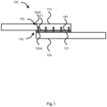
- Figure 1 shows a cross-section of a hybrid bonded-fastened, HBF, joint 100, according to an exemplary embodiment.
- the hybrid bonded-fastened, HBF, joint comprises: a first component 110 having a first joint surface 111, wherein the first component 110 is a composite component; a second component 120 having a second joint surface 121, wherein the second component 121 is a metallic component; a set of projections 130, including a first projection 130A, mutually interlocking the first component 110 and the second component 120 via the first joint surface 111 and the second joint surface 121; and an adhesive 140 mutually adhesively bonding the first component 110 and the second component 120 via the first joint surface 111 and the second joint surface 121; wherein the adhesive 140 comprises and/or is a disbondable adhesive.
- the set of projections 130 is provided by the second component 120.
- the first component 110 comprises a first set of apertures 150, including a first aperture 150A, arranged to receive the set of projections therein and/or therethrough.
- the first aperture 150A provides a clearance fit with respect to the first projection 130A, wherein the adhesive 140 infiltrates the first aperture 150A and mutually bonds the first projection 130A and walls of the first aperture 150A.
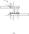
- Figure 2 shows a cross-section of the HBF joint 1 of Figure 1 , after disassembly.
- Figure 3 shows a method 300 according to an exemplary embodiment.
- the method is of joining a first component having a first joint surface, wherein the first component is a composite component, a metallic component or a ceramic component, and a second component having a second joint surface, wherein the second component is a composite component, a metallic component or a ceramic component.
- the method comprises: mutually interlocking the first component and the second component via the first joint surface and the second joint surface using a set of projections, including a first projection 302; and mutually adhesively bonding the first component and the second component via the first joint surface and the second joint surface using an adhesive 304; wherein the adhesive comprises and/or is a disbondable adhesive; thereby joining the first component and the second component using a hybrid bonded-fastened, HBF, joint.
- the first component comprises a first set of apertures, including a first aperture, arranged to receive the set of projections therein and/or therethrough.
- the first aperture provides a clearance fit with respect to the first projection, wherein the adhesive infiltrates the first aperture and mutually bonds the first projection and walls of the first aperture.
- the method may include any of the steps described with respect to the first aspect, the second aspect and/or the third aspect.
- FIG. 4 shows a method 400 according to an exemplary embodiment.
- the method is of disjoining a hybrid bonded-fastened, HBF, joint.
- the HBF joint comprises: a first component having a first joint surface, wherein the first component is a composite component, a metallic component or a ceramic component; a second component having a second joint surface, wherein the second component is a composite component, a metallic component or a ceramic component; a set of projections, including a first projection, mutually interlocking the first component and the second component via the first joint surface and the second joint surface; and an adhesive mutually adhesively bonding the first component and the second component via the first joint surface and the second joint surface; wherein the adhesive comprises and/or is a disbondable adhesive.
- the method comprises: mutually spacing apart the first component and the second component by disbonding the adhesive and thereby releasing the set of projections from the first joint surface and the second joint surface 402.
- the first component comprises a first set of apertures, including a first aperture, arranged to receive the set of projections therein and/or therethrough.
- the first aperture provides a clearance fit with respect to the first projection, wherein the adhesive infiltrates the first aperture and mutually bonds the first projection and walls of the first aperture. In this way, disbonding of the adhesive in the set of apertures further urges release of the set of projections therefrom.
- the method may include any of the steps described with respect to the first aspect, the second aspect and/or the third aspect.
- FIG. 5 shows a cross-section of a hybrid bonded-fastened, HBF, joint 500, according to an exemplary embodiment, before joining.
- the hybrid bonded-fastened, HBF, joint comprises: a first component 510 having a first joint surface 511, wherein the first component 510 is a composite component; a second component 520 having a second joint surface 521, wherein the second component 521 is a composite component; a set of projections 530, including a first projection 530A, mutually interlocking the first component 510 and the second component 520 via the first joint surface 511 and the second joint surface 521; and an adhesive 540 mutually adhesively bonding the first component 510 and the second component 520 via the first joint surface 511 and the second joint surface 521; wherein the adhesive 540 comprises and/or is a disbondable adhesive.
- the HBF joint comprises a metallic joint connector plate 560 having opposed joint surfaces, wherein the joint connector plate 560 is disposed between the first joint surface 511 and the second joint surface 521 and the set of projections 530 is provided by the joint connector plate 560.
- the first component 510 comprises a first set of apertures 550, including a first aperture 550A, arranged to receive the set of projections 530 therein and/or therethrough.
- the second component 520 comprises a second set of apertures 570, including a first aperture 570A, arranged to receive the set of projections 530 therein and/or therethrough.
- the first aperture 550A provides a clearance fit with respect to the first projection 530A, wherein the adhesive 540 infiltrates the first aperture 550A and mutually bonds the first projection 530A and walls of the first aperture 550A.
- the first projection 530A is a barbed pin.
- the first aperture 550A is a frustoconical aperture.
- respective apertures of the first set of apertures 550 and of the second set of apertures 570 are as described with respect to the first aperture 550A.
Landscapes
- Engineering & Computer Science (AREA)
- Mechanical Engineering (AREA)
- Chemical & Material Sciences (AREA)
- Organic Chemistry (AREA)
- Chemical Kinetics & Catalysis (AREA)
- General Chemical & Material Sciences (AREA)
- Standing Axle, Rod, Or Tube Structures Coupled By Welding, Adhesion, Or Deposition (AREA)
- Connection Of Plates (AREA)
- Adhesives Or Adhesive Processes (AREA)
Claims (15)
- Hybrid-verklebte-befestigte Fügung, HBF-Fügung (100), umfassend:eine erste Komponente (110), die eine erste Fügungsoberfläche (111) aufweist, wobei die erste Komponente (110) eine Verbundkomponente, eine metallische Komponente oder eine keramische Komponente ist;eine zweite Komponente (120), die eine zweite Fügungsoberfläche (121) aufweist, wobei die zweite Komponente (120) eine Verbundkomponente, eine metallische Komponente oder eine keramische Komponente ist; undeinen Satz von Vorsprüngen (130), einschließlich eines ersten Vorsprungs (130A), der die erste Komponente (110) und die zweite Komponente (120) über die erste Fügungsoberfläche (111) und die zweite Fügungsoberfläche (121) gegenseitig verriegelt, gekennzeichnet durch:
einen Klebstoff (140), der die erste Komponente (110) und die zweite Komponente (120) über die erste Fügungsoberfläche (111) und die zweite Fügungsoberfläche (121) gegenseitig adhäsiv verklebt, wobei der Klebstoff (140) einen lösbaren Klebstoff umfasst und/oder ein solcher ist. - HBF-Fügung (100) nach Anspruch 1, wobei der Satz von Vorsprüngen (130), mindestens teilweise, durch die zweite Komponente (120) bereitgestellt wird.
- HBF-Fügung (100) nach einem der vorhergehenden Ansprüche, wobei die erste Fügungsoberfläche (111) und die zweite Fügungsoberfläche (121) sich gegenseitig entsprechen, und wobei der Klebstoff (140) die erste Fügungsoberfläche (111) und die zweite Fügungsoberfläche (121) gegenseitig adhäsiv verklebt.
- HBF-Fügung (500) nach Anspruch 1, umfassend eine metallische Fügungsverbinderplatte (560), die gegenüberliegende Fügungsoberflächen aufweist, wobei die Fügungsverbinderplatte (560) zwischen der ersten Fügungsoberfläche (511) und der zweiten Fügungsoberfläche (521) angeordnet ist.
- HBF-Fügung (500) nach Anspruch 4, wobei der Satz von Vorsprüngen (530), mindestens teilweise, durch die Fügungsverbinderplatte (560) bereitgestellt wird.
- HBF-Fügung (500) nach Anspruch 5, wobei der Satz von Vorsprüngen (530) die erste Komponente (510) und optional die zweite Komponente (520) durchbohrt.
- HBF-Fügung (500) nach einem der Ansprüche 4 bis 6, wobei die Fügungsverbinderplatte (560) ein ferromagnetisches Metall umfasst und/oder ein solches ist.
- HBF-Fügung (500) nach einem der Ansprüche 4 bis 7, wobei die Fügungsverbinderplatte (560) einen Satz elektrischer Anschlüsse für Widerstandsheizung davon bereitstellt.
- HBF-Fügung (100) nach einem der vorhergehenden Ansprüche, umfassend einen metallischen Fügungseinsatz, wobei der Fügungseinsatz zwischen der ersten Fügungsoberfläche (111) und der zweiten Fügungsoberfläche (121) angeordnet ist, und wobei der Fügungseinsatz eine Formgedächtnislegierung oder einen Bimetallstreifen umfasst und/oder eine solche/ein solcher ist.
- HBF-Fügung (100) nach einem der vorhergehenden Ansprüche, wobei der Klebstoff (140) ein Funktionsadditiv umfasst.
- HBF-Fügung (100) nach einem der vorhergehenden Ansprüche, wobei die zweite Komponente (120) eine Verbundkomponente ist.
- Verfahren (300) zum Fügen einer ersten Komponente, die eine erste Fügungsoberfläche aufweist, wobei die erste Komponente eine Verbundkomponente, eine metallische Komponente oder eine keramische Komponente ist, und einer zweiten Komponente, die eine zweite Fügungsoberfläche aufweist, wobei die zweite Komponente eine Verbundkomponente, eine metallische Komponente oder eine keramische Komponente ist, das Verfahren umfassend:gegenseitig Verriegeln der ersten Komponente und der zweiten Komponente über die erste Fügungsoberfläche und die zweite Fügungsoberfläche unter Verwendung eines Satzes von Vorsprüngen, einschließlich eines ersten Vorsprungs (302); und gekennzeichnet durchgegenseitig adhäsiv Verkleben der ersten Komponente und der zweiten Komponente über die erste Fügungsoberfläche und die zweite Fügungsoberfläche unter Verwendung eines Klebstoffs (304);wobei der Klebstoff einen lösbaren Klebstoff umfasst und/oder ein solcher ist;wobei dadurch die erste und die zweite Komponente unter Verwendung einer hybrid-verklebten-befestigten Fügung, HBF-Fügung, gefügt werden.
- Verfahren (300) nach Anspruch 12, umfassend das Anordnen einer metallischen Fügungsverbinderplatte, die gegenüberliegende Fügungsoberflächen zwischen der ersten Fügungsoberfläche und der zweiten Fügungsoberfläche aufweist.
- Verfahren (400) zum Entfügen einer hybrid-verklebten-befestigten Fügung, HBF-Fügung, nach einem der Ansprüche 1 bis 11;
wobei das Verfahren umfasst:
gegenseitiges Beabstanden der ersten Komponente und der zweiten Komponente durch Lösen des Klebstoffs und dadurch Lösen des Satzes von Vorsprüngen von der ersten Fügungsoberfläche und der zweiten Fügungsoberfläche (402). - Verfahren (400) nach Anspruch 14, wobei das Lösen des Klebstoffs das gegenseitige Beabstanden der ersten Komponente und der zweiten Komponente umfasst.
Applications Claiming Priority (3)
| Application Number | Priority Date | Filing Date | Title |
|---|---|---|---|
| GB2118131.8A GB2613806A (en) | 2021-12-15 | 2021-12-15 | Hybrid joint |
| EP21275185.3A EP4197753A1 (de) | 2021-12-15 | 2021-12-15 | Hybridgelenk |
| PCT/GB2022/053146 WO2023111521A1 (en) | 2021-12-15 | 2022-12-09 | Hybrid joint |
Publications (3)
| Publication Number | Publication Date |
|---|---|
| EP4448256A1 EP4448256A1 (de) | 2024-10-23 |
| EP4448256C0 EP4448256C0 (de) | 2025-06-25 |
| EP4448256B1 true EP4448256B1 (de) | 2025-06-25 |
Family
ID=84537216
Family Applications (1)
| Application Number | Title | Priority Date | Filing Date |
|---|---|---|---|
| EP22826186.3A Active EP4448256B1 (de) | 2021-12-15 | 2022-12-09 | Hybridverbund |
Country Status (5)
| Country | Link |
|---|---|
| US (1) | US20240416593A1 (de) |
| EP (1) | EP4448256B1 (de) |
| JP (1) | JP7676670B2 (de) |
| ES (1) | ES3037877T3 (de) |
| WO (1) | WO2023111521A1 (de) |
Citations (1)
| Publication number | Priority date | Publication date | Assignee | Title |
|---|---|---|---|---|
| US20130149501A1 (en) * | 2009-12-08 | 2013-06-13 | Airbus Operations Gmbh | Method for connecting a fibre composite component to a structural component of an aircraft and spacecraft and a corresponding arrangement |
Family Cites Families (5)
| Publication number | Priority date | Publication date | Assignee | Title |
|---|---|---|---|---|
| US5571721A (en) * | 1994-05-05 | 1996-11-05 | Erie Scientific Company | Improved biological culture slide and method of making same |
| DE102005006937A1 (de) * | 2005-02-16 | 2006-08-24 | Volkswagen Ag | Fügeverbindung von Bauteilen |
| US9909605B2 (en) | 2012-10-22 | 2018-03-06 | Bae Systems Plc | Hybrid joint manufacturing |
| US10099458B2 (en) | 2015-03-23 | 2018-10-16 | Board Of Trustees Of Michigan State University | Reversible adhesive compositions and related methods |
| US10975207B2 (en) * | 2019-03-15 | 2021-04-13 | Lenovo (Singapore) Pte. Ltd. | System, method, and apparatus for attaching structures |
-
2022
- 2022-12-09 EP EP22826186.3A patent/EP4448256B1/de active Active
- 2022-12-09 ES ES22826186T patent/ES3037877T3/es active Active
- 2022-12-09 JP JP2024535784A patent/JP7676670B2/ja active Active
- 2022-12-09 WO PCT/GB2022/053146 patent/WO2023111521A1/en not_active Ceased
- 2022-12-09 US US18/720,364 patent/US20240416593A1/en active Pending
Patent Citations (1)
| Publication number | Priority date | Publication date | Assignee | Title |
|---|---|---|---|---|
| US20130149501A1 (en) * | 2009-12-08 | 2013-06-13 | Airbus Operations Gmbh | Method for connecting a fibre composite component to a structural component of an aircraft and spacecraft and a corresponding arrangement |
Also Published As
| Publication number | Publication date |
|---|---|
| JP2024546922A (ja) | 2024-12-26 |
| US20240416593A1 (en) | 2024-12-19 |
| EP4448256C0 (de) | 2025-06-25 |
| WO2023111521A1 (en) | 2023-06-22 |
| ES3037877T3 (en) | 2025-10-07 |
| JP7676670B2 (ja) | 2025-05-14 |
| EP4448256A1 (de) | 2024-10-23 |
Similar Documents
| Publication | Publication Date | Title |
|---|---|---|
| Banea | Debonding on demand of adhesively bonded joints: A critical review | |
| EP1423256B1 (de) | Schweisstechniken für komponenten aus polymer oder polymerverbundstoffen | |
| AU671749B2 (en) | A reinforced joint for composite structures and method of joining composite parts | |
| KR101983613B1 (ko) | 열경화성 폴리머 컴포넌트에 열가소성 폴리머를 접합하기 위한 방법 | |
| CN101474658A (zh) | 组装复合材料结构的方法和装置 | |
| EP2909486B1 (de) | Hybridverbindungsherstellung | |
| JPWO2008133296A1 (ja) | ステンレス鋼複合体とその製造方法 | |
| JP2015536265A (ja) | 低温熱可塑性フィルム融着を利用した複合部品の接合 | |
| CN116141686B (zh) | 连续纤维增强热塑性复合材料与金属的超声复合铆焊方法 | |
| EP4197753A1 (de) | Hybridgelenk | |
| EP3817912B1 (de) | Kupplungselement, kupplungsanordnung mit einem solchen kupplungselement und verfahren zum verbinden eines ersten substrats mit einem solchen kupplungselement | |
| JP2011042030A (ja) | 金属と被着物の接合体、及びその製造方法 | |
| US20240416593A1 (en) | Hybrid joint | |
| US20050042023A1 (en) | Structural assemblies using integrally molded, and welded mechanically locking z-pins | |
| CN103016477B (zh) | 联结镁的方法 | |
| GB2613806A (en) | Hybrid joint | |
| US9387655B2 (en) | Nano-engineered structural joints: materials, procedures and applications thereof | |
| US7588179B2 (en) | Bonding of carbon fibers to metal inserts for use in composites | |
| JP2004189856A (ja) | 接着体およびそれを用いたリサイクル方法 | |
| CN116551174A (zh) | 一种基于均匀温度场的异质接头焊接系统和焊接方法 | |
| JPH11207826A (ja) | 樹脂製インテークマニホールドの製造方法 | |
| CN111163884A (zh) | 用于桥接部件的系统和方法 | |
| EP4299922B1 (de) | Verfahren zum befestigen eines teiles an einem anderen teil unter verwendung von elektrisch verformbaren nieten | |
| EP4098428A1 (de) | Verfahren zum verbinden von polymermatrixverstärkten verbundwerkstoffen | |
| CN112412935B (zh) | 一种塑钢复合材料自锁连接件及其连接方法 |
Legal Events
| Date | Code | Title | Description |
|---|---|---|---|
| STAA | Information on the status of an ep patent application or granted ep patent |
Free format text: STATUS: UNKNOWN |
|
| STAA | Information on the status of an ep patent application or granted ep patent |
Free format text: STATUS: THE INTERNATIONAL PUBLICATION HAS BEEN MADE |
|
| PUAI | Public reference made under article 153(3) epc to a published international application that has entered the european phase |
Free format text: ORIGINAL CODE: 0009012 |
|
| STAA | Information on the status of an ep patent application or granted ep patent |
Free format text: STATUS: REQUEST FOR EXAMINATION WAS MADE |
|
| 17P | Request for examination filed |
Effective date: 20240607 |
|
| AK | Designated contracting states |
Kind code of ref document: A1 Designated state(s): AL AT BE BG CH CY CZ DE DK EE ES FI FR GB GR HR HU IE IS IT LI LT LU LV MC ME MK MT NL NO PL PT RO RS SE SI SK SM TR |
|
| GRAP | Despatch of communication of intention to grant a patent |
Free format text: ORIGINAL CODE: EPIDOSNIGR1 |
|
| STAA | Information on the status of an ep patent application or granted ep patent |
Free format text: STATUS: GRANT OF PATENT IS INTENDED |
|
| RIC1 | Information provided on ipc code assigned before grant |
Ipc: B29C 65/50 20060101ALN20250115BHEP Ipc: C09J 5/00 20060101ALI20250115BHEP Ipc: B29C 65/72 20060101ALI20250115BHEP Ipc: B29C 65/48 20060101ALI20250115BHEP Ipc: B29C 65/56 20060101ALI20250115BHEP Ipc: B29C 65/00 20060101ALI20250115BHEP Ipc: B29C 65/64 20060101ALI20250115BHEP Ipc: B29C 65/76 20060101AFI20250115BHEP |
|
| DAV | Request for validation of the european patent (deleted) | ||
| DAX | Request for extension of the european patent (deleted) | ||
| INTG | Intention to grant announced |
Effective date: 20250207 |
|
| GRAS | Grant fee paid |
Free format text: ORIGINAL CODE: EPIDOSNIGR3 |
|
| GRAA | (expected) grant |
Free format text: ORIGINAL CODE: 0009210 |
|
| STAA | Information on the status of an ep patent application or granted ep patent |
Free format text: STATUS: THE PATENT HAS BEEN GRANTED |
|
| AK | Designated contracting states |
Kind code of ref document: B1 Designated state(s): AL AT BE BG CH CY CZ DE DK EE ES FI FR GB GR HR HU IE IS IT LI LT LU LV MC ME MK MT NL NO PL PT RO RS SE SI SK SM TR |
|
| REG | Reference to a national code |
Ref country code: GB Ref legal event code: FG4D |
|
| REG | Reference to a national code |
Ref country code: CH Ref legal event code: EP |
|
| REG | Reference to a national code |
Ref country code: DE Ref legal event code: R096 Ref document number: 602022016604 Country of ref document: DE |
|
| REG | Reference to a national code |
Ref country code: CH Ref legal event code: EP |
|
| REG | Reference to a national code |
Ref country code: IE Ref legal event code: FG4D |
|
| U01 | Request for unitary effect filed |
Effective date: 20250717 |
|
| U07 | Unitary effect registered |
Designated state(s): AT BE BG DE DK EE FI FR IT LT LU LV MT NL PT RO SE SI Effective date: 20250724 |
|
| REG | Reference to a national code |
Ref country code: ES Ref legal event code: FG2A Ref document number: 3037877 Country of ref document: ES Kind code of ref document: T3 Effective date: 20251007 |
|
| PG25 | Lapsed in a contracting state [announced via postgrant information from national office to epo] |
Ref country code: GR Free format text: LAPSE BECAUSE OF FAILURE TO SUBMIT A TRANSLATION OF THE DESCRIPTION OR TO PAY THE FEE WITHIN THE PRESCRIBED TIME-LIMIT Effective date: 20250926 Ref country code: NO Free format text: LAPSE BECAUSE OF FAILURE TO SUBMIT A TRANSLATION OF THE DESCRIPTION OR TO PAY THE FEE WITHIN THE PRESCRIBED TIME-LIMIT Effective date: 20250925 |
|
| PG25 | Lapsed in a contracting state [announced via postgrant information from national office to epo] |
Ref country code: HR Free format text: LAPSE BECAUSE OF FAILURE TO SUBMIT A TRANSLATION OF THE DESCRIPTION OR TO PAY THE FEE WITHIN THE PRESCRIBED TIME-LIMIT Effective date: 20250625 |
|
| PG25 | Lapsed in a contracting state [announced via postgrant information from national office to epo] |
Ref country code: RS Free format text: LAPSE BECAUSE OF FAILURE TO SUBMIT A TRANSLATION OF THE DESCRIPTION OR TO PAY THE FEE WITHIN THE PRESCRIBED TIME-LIMIT Effective date: 20250925 |
|
| U20 | Renewal fee for the european patent with unitary effect paid |
Year of fee payment: 4 Effective date: 20251119 |
|
| PG25 | Lapsed in a contracting state [announced via postgrant information from national office to epo] |
Ref country code: IS Free format text: LAPSE BECAUSE OF FAILURE TO SUBMIT A TRANSLATION OF THE DESCRIPTION OR TO PAY THE FEE WITHIN THE PRESCRIBED TIME-LIMIT Effective date: 20251025 |
|
| PG25 | Lapsed in a contracting state [announced via postgrant information from national office to epo] |
Ref country code: SM Free format text: LAPSE BECAUSE OF FAILURE TO SUBMIT A TRANSLATION OF THE DESCRIPTION OR TO PAY THE FEE WITHIN THE PRESCRIBED TIME-LIMIT Effective date: 20250625 |
|
| PGFP | Annual fee paid to national office [announced via postgrant information from national office to epo] |
Ref country code: TR Payment date: 20251202 Year of fee payment: 4 |
|
| PG25 | Lapsed in a contracting state [announced via postgrant information from national office to epo] |
Ref country code: CZ Free format text: LAPSE BECAUSE OF FAILURE TO SUBMIT A TRANSLATION OF THE DESCRIPTION OR TO PAY THE FEE WITHIN THE PRESCRIBED TIME-LIMIT Effective date: 20250625 |
|
| PG25 | Lapsed in a contracting state [announced via postgrant information from national office to epo] |
Ref country code: PL Free format text: LAPSE BECAUSE OF FAILURE TO SUBMIT A TRANSLATION OF THE DESCRIPTION OR TO PAY THE FEE WITHIN THE PRESCRIBED TIME-LIMIT Effective date: 20250625 |
|
| PG25 | Lapsed in a contracting state [announced via postgrant information from national office to epo] |
Ref country code: SK Free format text: LAPSE BECAUSE OF FAILURE TO SUBMIT A TRANSLATION OF THE DESCRIPTION OR TO PAY THE FEE WITHIN THE PRESCRIBED TIME-LIMIT Effective date: 20250625 |
|
| PGFP | Annual fee paid to national office [announced via postgrant information from national office to epo] |
Ref country code: ES Payment date: 20260102 Year of fee payment: 4 |
|
| PLBE | No opposition filed within time limit |
Free format text: ORIGINAL CODE: 0009261 |
|
| STAA | Information on the status of an ep patent application or granted ep patent |
Free format text: STATUS: NO OPPOSITION FILED WITHIN TIME LIMIT |
|
| REG | Reference to a national code |
Ref country code: CH Ref legal event code: L10 Free format text: ST27 STATUS EVENT CODE: U-0-0-L10-L00 (AS PROVIDED BY THE NATIONAL OFFICE) Effective date: 20260507 |