EP4446748A2 - Vorrichtung zum routen einer fördervorrichtung von biologischen proben in einem laborautomatisierungssystem - Google Patents
Vorrichtung zum routen einer fördervorrichtung von biologischen proben in einem laborautomatisierungssystem Download PDFInfo
- Publication number
- EP4446748A2 EP4446748A2 EP24163756.0A EP24163756A EP4446748A2 EP 4446748 A2 EP4446748 A2 EP 4446748A2 EP 24163756 A EP24163756 A EP 24163756A EP 4446748 A2 EP4446748 A2 EP 4446748A2
- Authority
- EP
- European Patent Office
- Prior art keywords
- diverting
- conveying devices
- lane
- connecting section
- conveyor
- Prior art date
- Legal status (The legal status is an assumption and is not a legal conclusion. Google has not performed a legal analysis and makes no representation as to the accuracy of the status listed.)
- Withdrawn
Links
Images


Classifications
-
- G—PHYSICS
- G01—MEASURING; TESTING
- G01N—INVESTIGATING OR ANALYSING MATERIALS BY DETERMINING THEIR CHEMICAL OR PHYSICAL PROPERTIES
- G01N35/00—Automatic analysis not limited to methods or materials provided for in any single one of groups G01N1/00 - G01N33/00; Handling materials therefor
- G01N35/02—Automatic analysis not limited to methods or materials provided for in any single one of groups G01N1/00 - G01N33/00; Handling materials therefor using a plurality of sample containers moved by a conveyor system past one or more treatment or analysis stations
- G01N35/04—Details of the conveyor system
-
- G—PHYSICS
- G01—MEASURING; TESTING
- G01N—INVESTIGATING OR ANALYSING MATERIALS BY DETERMINING THEIR CHEMICAL OR PHYSICAL PROPERTIES
- G01N35/00—Automatic analysis not limited to methods or materials provided for in any single one of groups G01N1/00 - G01N33/00; Handling materials therefor
- G01N35/00584—Control arrangements for automatic analysers
- G01N35/00722—Communications; Identification
- G01N35/00732—Identification of carriers, materials or components in automatic analysers
-
- G—PHYSICS
- G01—MEASURING; TESTING
- G01N—INVESTIGATING OR ANALYSING MATERIALS BY DETERMINING THEIR CHEMICAL OR PHYSICAL PROPERTIES
- G01N35/00—Automatic analysis not limited to methods or materials provided for in any single one of groups G01N1/00 - G01N33/00; Handling materials therefor
- G01N35/02—Automatic analysis not limited to methods or materials provided for in any single one of groups G01N1/00 - G01N33/00; Handling materials therefor using a plurality of sample containers moved by a conveyor system past one or more treatment or analysis stations
- G01N35/025—Automatic analysis not limited to methods or materials provided for in any single one of groups G01N1/00 - G01N33/00; Handling materials therefor using a plurality of sample containers moved by a conveyor system past one or more treatment or analysis stations having a carousel or turntable for reaction cells or cuvettes
-
- G—PHYSICS
- G01—MEASURING; TESTING
- G01N—INVESTIGATING OR ANALYSING MATERIALS BY DETERMINING THEIR CHEMICAL OR PHYSICAL PROPERTIES
- G01N35/00—Automatic analysis not limited to methods or materials provided for in any single one of groups G01N1/00 - G01N33/00; Handling materials therefor
- G01N35/02—Automatic analysis not limited to methods or materials provided for in any single one of groups G01N1/00 - G01N33/00; Handling materials therefor using a plurality of sample containers moved by a conveyor system past one or more treatment or analysis stations
- G01N35/04—Details of the conveyor system
- G01N2035/0401—Sample carriers, cuvettes or reaction vessels
-
- G—PHYSICS
- G01—MEASURING; TESTING
- G01N—INVESTIGATING OR ANALYSING MATERIALS BY DETERMINING THEIR CHEMICAL OR PHYSICAL PROPERTIES
- G01N35/00—Automatic analysis not limited to methods or materials provided for in any single one of groups G01N1/00 - G01N33/00; Handling materials therefor
- G01N35/02—Automatic analysis not limited to methods or materials provided for in any single one of groups G01N1/00 - G01N33/00; Handling materials therefor using a plurality of sample containers moved by a conveyor system past one or more treatment or analysis stations
- G01N35/04—Details of the conveyor system
- G01N2035/046—General conveyor features
- G01N2035/0467—Switching points ("aiguillages")
- G01N2035/047—Switching points ("aiguillages") diverging, e.g. sending carriers to different analysers
-
- G—PHYSICS
- G01—MEASURING; TESTING
- G01N—INVESTIGATING OR ANALYSING MATERIALS BY DETERMINING THEIR CHEMICAL OR PHYSICAL PROPERTIES
- G01N35/00—Automatic analysis not limited to methods or materials provided for in any single one of groups G01N1/00 - G01N33/00; Handling materials therefor
- G01N35/02—Automatic analysis not limited to methods or materials provided for in any single one of groups G01N1/00 - G01N33/00; Handling materials therefor using a plurality of sample containers moved by a conveyor system past one or more treatment or analysis stations
- G01N35/04—Details of the conveyor system
- G01N2035/0496—Other details
Definitions
- the present invention concerns an apparatus for routing a conveying device of biological samples in a laboratory automation system.
- each biological sample travels within a laboratory automation system placed in a container (e.g. a test tube) that is in turn housed by a conveying device moved by an automatic conveyor, preferably of the belt type.
- a container e.g. a test tube
- a conveying device moved by an automatic conveyor, preferably of the belt type.
- main lane preferably a close loop, which covers the entire extension of the automation system, and which in turn branches off at each module interfaced to the system into a secondary lane along which to route the transport devices which need to be routed towards that module.
- this diversion is accomplished by stopping the conveying device at a stop gate preceding the diverting point and laterally protruding from the profile of the automation system: only upon detection of the conveying device (preferably by means of an antenna placed under the belt of the automatic conveyor) and eventually of the test tube (preferably by a presence sensor), and upon confirmation by the central control unit of the arrival of the expected sample, there is the diversion of the conveying device into the secondary lane according to any known mechanism.
- the object of the present invention is to develop a routing apparatus that overcomes the drawbacks of the known solutions, by ensuring a diversion of conveying devices with test tube that does not cause biological sample spillage from the uncapped test tubes being diverted.
- a further object is to ensure an optimized activation of the routing apparatus, minimizing unnecessary movements of the components used to preserve them from wear and thus from malfunctions or breakages.
- Still one object is to realize a routing apparatus with simple and low-cost means.
- the invention relates to a laboratory automation system comprising at least one process station having an automatic conveyor for the transit of conveying devices of containers of biological samples,
- the diverting members are contact profiles spaced along opposite sides of the connecting section, mutually connected by means of a bridge profile comprising side connecting flanges joined by a horizontal section spaced above the transport plane of the conveyor and the contact profiles.
- the contact profiles are configured movable along a horizontal cross direction with respect to the transit direction of the conveying devices, to alternately assume said first or second diverting position, such that the conveying devices arriving at the connecting section are forced to follow the path defined by the position of the contact profiles, which respectively come into contact with opposite side portions of the conveying devices running in line and arriving one after the other at the connecting section.
- each lever comprises an elongated body with an arcuate shape having opposite main faces substantially parallel to the transport plane of the conveyor, wherein each elongated body comprises a lower surface parallel to and facing towards the transport plane of the conveyor, an upper surface opposite to the lower surface and connected to the respective shaft, the levers comprising a proximal portion connected to the shafts and being controlled with a controlled rotational motion to impact with the side surfaces of an upper portion of the conveying devices.
- the invention also relates to a process for routing conveying devices of containers of biological samples along an automatic conveyor of a process station, comprising the following steps:
- a known laboratory automation system used for the transport of biological samples is formed by a series of process stations 2, such as the one shown in Figure 1 , assembled together in various numbers and according to different configurations to meet the specific needs of each analysis laboratory.
- Each process station 2 has an automatic conveyor 3 for the transit of containers of biological samples 4 (shown in Figures 5 , 6 ), preferably test tubes, each inserted into a conveying device 5.
- the conveying devices 5 can be made according to what is described in European Patent EP 3129791 B1 in the name of the same Applicant.
- the automatic conveyor 3 is in turn made according to a known configuration of any type, for example comprising a conveyor belt for dragging the conveying devices 5.
- the automatic conveyor 3 has lanes for the flow of the conveying devices 5, and in particular a main lane 20 positioned internally and substantially configured for the ordinary transport of conveying devices 5, flanked in parallel by a secondary lane 21 typically intended instead to interface the conveying devices 5 flowing therein to a processing module 6 of biological samples, e.g. a pre-analysis, analysis or post-analysis module, preferably located on the outer side of the automation system ( Figure 1 ).
- a processing module 6 of biological samples e.g. a pre-analysis, analysis or post-analysis module, preferably located on the outer side of the automation system ( Figure 1 ).
- the flow of the conveying devices 5 along the main lane 20 and the secondary lane 21 occurs with identical transit sense.
- the transit sense of a lane is determined by the order of two lane points on which one conveying device 5 passes.
- each conveying device 5 from the main lane 20 to the secondary lane 21 is achieved by means of an appropriate routing apparatus, globally indicated in Figure 2 by the number 1 with reference to a configuration according to the prior art.
- the routing apparatus 1 comprises a known type of diverting mechanism, such as a cam 8, which protrudes laterally from the main lane 20 and is able to activate upon detection of the conveying device 5 to be diverted by identification and control means - for example based on RFID technology - comprising an antenna 9 able to detect the passage of each conveying device 5.
- the antenna 9 is below the conveyor belt of the conveyor 3 and is positioned upstream of the routing apparatus 1.
- There is also a central control unit E of the entire automation system able to communicate with the single process station and to manage the appropriate routing of the conveying devices 5.
- the construction profile 30 of the automatic conveyor 3 is thus shaped in such a way as to allow, upstream of the diversion, the ordinary flow of conveying devices 5, and thus of biological samples contained in the respective test tubes 4, only along the main lane 20. Only after any subsequent activation of the diverting mechanism (represented by the cam 8), the conveying devices 5 that need to be diverted towards the secondary lane 21 are appropriately pushed towards the latter, thus crossing a connecting section 7 between the two lanes 20, 21 obtained along the automatic conveyor 3.
- FIGS 3 , 4 and 5-9 respectively illustrate two embodiments of a routing apparatus 10, according to the present invention.
- the routing apparatus 10 comprises a diverting mechanism 40, associated with a connecting section 7, configured to impact the conveying devices 5 passing through the connecting section 7, in order to route them towards the main lane 20 or the secondary lane 21.
- the diverting mechanism 40 comprises two diverting members 40a, 40b, 70a, 70b, 80a, 80b configured movable and simultaneously controllable to jointly achieve a first diverting position and a second diverting position, able to respectively route the conveying devices 5 to the main lane 20 or the secondary lane 21.
- the routing apparatus 10 is implemented in a laboratory automation system comprising one or more process stations 2.
- the process station 2 comprises an automatic conveyor 3 for the transit of biological samples containers 4, preferably test tubes, each inserted into a conveying device 5.
- conveying devices 5 without containers of biological samples 4 are shown in Figures 3 , 4 .
- the automatic conveyor 3 comprises lanes 20, 21 for the flow of the conveying devices 5.
- the main lane 20 and secondary lane 21 have in themselves the same configuration as the prior art, meaning they are placed parallel to each other.
- the construction profile 300 of the automatic conveyor 3 is shaped to create upstream of the connecting section 7 a single transit lane 19 for the conveying devices 5.
- the conveyor 3 provides a single row of conveying devices 5, which are then diverted by the diverting mechanism 40 towards the main lane 20 or the secondary lane 21.
- said single transit lane 19 develops an undulating path oriented so that the conveying devices 5 are channeled directly at the connecting section 7, e.g. at a position equidistant between the main lane 20 and the secondary lane 21.
- the diverting mechanism 40 comprises two contact profiles 40a, 40b spaced along opposite sides of the end part of the single transit lane 19 that flows into the connecting section 7.
- the contact profiles 40a, 40b are mutually connected by means of a bridge profile 40c comprising a pair of side connecting flanges 18 joined by a horizontal section 17 spaced above the lane 19 and the contact profiles 40a, 40b.
- the connecting flanges 18 are rigidly connected to an upper face of the contact profiles 40a, 40b.
- the contact profiles 40a, 40b are simultaneously movable along a horizontal cross direction with respect to the transit direction of the conveying devices 5, to alternately assume two positions (illustrated in Figures 3 , 4 ) able to laterally impact the conveying devices 5 to appropriately route them, one after the other, along the main lane 20 or the secondary lane 21.
- the movement of the contact profiles 40a, 40b can be controlled by an actuator 50 of any known type.
- a row of conveying devices 5 flows along the single lane 19.
- the diverting mechanism 40 controlled to alternately assume two positions: a first diverting position able to convey the conveying devices 5 along the main lane 20 (as illustrated in Figure 3 ) and a second diverting position able to convey the conveying devices 5 along the secondary lane 21 (as illustrated in Figure 4 ).
- Contact profiles 40a, 40b are shaped with a protruding portion towards the lane 19 able to laterally impact the conveying device 5 to appropriately route it along the main lane 20 or the secondary lane 21.
- the conveying devices 5 arriving at the connecting section 7 are forced to follow the path defined by the position of the contact profiles 40a, 40b, which respectively come into contact with opposite side portions of the conveying devices 5 running in line and arriving one after the other at the connecting section 7 and at the diverting mechanism 40.
- the movement of the bridge profile 40c, and consequently of the two contact profiles 40a, 40b, in a horizontal direction perpendicular to the flow of the conveying devices 5 is facilitated by the activation of a pneumatic cylinder with rod 50 connected to it and arranged laterally to the conveyor 3.
- the rod 50 is connected to one of the side connecting flanges 18, thereby causing the motion of the bridge profile 40c and the contact profiles 40a, 40b, which move solidly with the bridge profile 40c.
- the antenna 9 for detecting the conveying devices 5 is placed, similarly to the prior art, below the conveyor belt of the automatic conveyor 3 and in particular preferably below the belt upstream of the connecting section 7.
- the antenna 9 is located sufficiently upstream of the beginning of the undulating section of the construction profile 300, along the transit direction of the conveying devices 5, so that the detection performed by the antenna 9 on each of the conveying devices 5 results in an information, which is then retrieved by the central control unit E of the automation system (illustrated in Figures 3 , 4 ), regarding the need to route each detected conveying device 5 along the main lane 20 or the secondary lane 21.
- the diverting mechanism 40 is appropriately activated, e.g.
- the movement of the actuator 50 brings the two contact profiles 40a, 40b to the position able to direct the conveying device 5 to the main lane 20 or the secondary lane 21.
- the features and components necessary for identifying the conveying devices 5 passing through towards the diverting mechanism 40 can be made in accordance with what is described in patent EP 2780724 B1 in the name of the same Applicant.
- each conveying device 5 undergoes is such that the diverting mechanism 40 essentially becomes a continuation of the construction profile 300 ( Figures 3 , 4 ), able to push the conveying device 5 whichever lane it is to be diverted into.
- This coupled with the fact that the conveying device 5 essentially receives a thrust from the midpoint of the connecting section 7 between the two lanes 20, 21, causes it to travel midstroke compared to the diverting mechanisms according to the prior art, in which it must instead completely move from the main lane 20 to the secondary lane 21 in the event of a diversion. So the thrust it experiences, in the apparatus according to the invention, is more limited, though certainly sufficient to route the conveying device 5 into the appropriate lane.
- the configuration of the routing apparatus 10 according to the invention certainly lends itself to ensure full functionality if the conveying devices 5 are to be diverted alternately between the main lane 20 and the secondary lane 21: the movement of the diverting mechanism 40 along its axis, perpendicular to the direction of flow of the conveying devices 5, is indeed such as to bear the arrival in rapid succession and the appropriate routing of conveying devices 5.
- Figure 3 represents the situation wherein the arriving conveying devices 5 are routed along the main lane 20
- the successive Figure 4 depicts the moment wherein after the movement of the diverting mechanism 40 (cylinder with rod 50, bridge 40c and profiles 40a, 40b) the conveying devices 5 are now routed along the secondary lane 21.
- the use of the routing apparatus 10 according to the invention is particularly suitable especially in the case wherein a number of consecutive conveying devices 5 are to be routed along the same lane. In such a situation, indeed, it becomes necessary to move the diverting mechanism 40 only when the first among them arrives. Thereafter the diverting mechanism 40 remains stationary while still correctly routing the next conveying devices 5, meanwhile all previously detected by the antenna 9, and which at that point are not pushed but only accompanied.
- the diverting mechanism 40 receives from the central control unit E the appropriate command to move towards the complementary position and the conveying device 5 is thus routed towards the other lane 20, 21.
- the diverting mechanism 40 in the not infrequent situations in which several consecutive conveying devices 5 must undergo the same routing, is activated a considerably lower number of times than with the diverters of the known solutions, in which instead the presence of a certain number of consecutive conveying devices 5 all to be diverted along the secondary lane 21 requires the activation of the diverter (e.g. the cam 8 shown in Figure 1 ) for each of them.
- the diverter e.g. the cam 8 shown in Figure 1
- routing apparatus 10 of the invention makes the two lanes 20, 21 interchangeable, more easily foreshadowing a potential reorganization of the arrangement of machinery interfacing with the laboratory automation system, for example the repositioning of a module 6 along the inner lane of the conveyor 3 instead of the outer lane.
- Figures 5-9 illustrate an alternative and preferred embodiment of the present invention.
- Figures 5 , 6 are perspective views illustrating the routing apparatus 10 with the observer upstream and downstream of the diverting mechanism 40, respectively.
- the diverting mechanism 40 comprises a pair of levers 70a, 70b controlled in rotation by a leverage 60 mounted near the connecting section 7.
- Levers 70a, 70b are simultaneously controllable to jointly achieve a first diverting position (as shown in Figure 8 ) and a second diverting position (as shown in Figure 9 ), suitable to impact the conveying devices 5 and route them towards the lanes 20, 21.
- Levers 70a, 70b are indirectly connected to the linkage 60, as they are respectively keyed to a pair of shafts 61a, 61b directly controlled in rotation by the leverage 60.
- Shafts 61a, 61b vertically extend parallel and spaced apart above conveyor 3, without obstructing the passage of the conveying devices 5 and test tubes 4 along the lanes 20, 21.
- Shafts 61a, 61b are coaxially inserted in turn within fixed sleeves 62a, 62b ( Figures 5 , 6 ), each equipped with upper and lower bearings 63.
- the sectional view of Figure 7 illustrating the shafts 61a, 61b internally extended within the sleeves 62a, 62b.
- Each lever 70a, 70b comprises an elongated body with an arcuate shape having opposite main faces substantially parallel to the transport plane of the conveyor 3.
- Each elongated body comprises a lower surface parallel to and facing towards the transport plane of the conveyor 3, an upper surface 16 opposite to the lower surface and connected to the shafts 61a, 61b, an inner side surface facing the inner side surface of the other lever, and an outer side surface opposite to the inner side surface.
- the elongated body with an arcuate shape of each lever 70a, 70b comprises a proximal portion connected to the shafts 61a, 61b and a distal portion with a width less than that of the proximal portion.
- Leverage 60 is mounted on a bridge structure 11 comprising side vertical support portions 12, respectively extending at the opposite sides of the conveyor 3. Such side vertical portions 12 are mutually connected by a horizontal section 13 spaced above the conveyor 3, having a lower face facing the conveyor 3 and an opposite upper face above which the leverage 60 is mounted.
- the upper end of sleeves 62a, 62b is connected to the lower face of the horizontal section 13, thereby supporting the sleeves 62a, 62b above the conveyor 3.
- respective portions of the lower end of shafts 61a, 61b, to which levers 70a, 70b are connected protrude from the lower end of the sleeves 62a, 62b.
- levers 70a,70b mainly extend along a plane parallel to and spaced above the transport plane of the devices 5, so that they can impact with the side surfaces of an upper portion 51 of the conveying devices 5.
- Leverage 60 is operatively connected to the upper end of the shafts 61a, 61b, to transmit a rotational command to the levers 70a, 70b.
- Leverage 60 comprises parallel and integral connecting rods 15, mutually connected by a drive bar 14.
- the rotation of the first connecting rod controlled by the actuator is transmitted by means of the drive bar 14 to the other two connecting rods, which control in rotation the shafts 61a, 61b around their vertical axis, thus moving the levers 70a, 70b with a controlled rotational motion.
- the leverage 60 can comprise other known mechanisms, e.g. a gear by means of cogwheels.
- the leverage 60 is appropriately activated by an actuator - for example an electric motor 65 - always controlled on a software level by the central control unit E (indicated in Figure 5 ).
- the rotation of the shafts 61a, 61b leads to the movement, still alternating between two end positions, of the levers 70a and 70b ( Figures 6 , 8 , 9 ), which carry out the routing of the transport devices 5 along one or the other between the two lanes 20, 21 in a similar way as previously described.
- the central control unit E is able to impart a rotational command, preferably about 50°, to the electric motor 65.
- the two lanes 20, 21 also extend upstream of the connecting section 7 and the diverting mechanism 40, thus allowing the circulation of two parallel rows of conveying devices 5 also upstream of the routing apparatus 10. It should also be noted that upstream of the connecting section 7 and near it, the lanes have a slightly curved parallel path.
- one of the two levers (indicated with the reference 70a and referred to in the following as the "first lever”) has its proximal portion placed laterally with respect to the main lane 20, while the other of said two levers (indicated with the reference 70b and referred to in the following as the "second lever”) has its proximal portion placed between the main lane 20 and the secondary lane 21.
- the levers 70a, 70b are arranged to act on two conveying devices 5 placed side by side belonging to two different rows passing simultaneously through the connecting section 7.
- Figures 8 , 9 are elevation views illustrating the two different diverting positions of the levers 70a, 70b.
- first lever 70a extends along an outer side of the main lane 20, and the second lever 70b extends between the main lane 20 and the secondary lane 21.
- first lever 70a does not affect the path of the conveying devices 5, while the second lever 70b comes into contact with the conveying devices 5 passing through the main lane 20, causing them to still continue along the main lane 20 downstream of the connecting section 7.
- the inner side face of the second lever 70b comes into contact with the side surface 51 of an upper portion of the conveying devices 5, which run in line and come into contact one after the other with the second lever 70b.
- levers 70a, 70b do not come into contact with the conveying devices 5 passing through the secondary lane 21 upstream of the connecting section 7, which are then free to continue their path along the secondary lane 21 downstream of the diverting mechanism 40.
- the first lever 70a comes into contact with the conveying devices 5 passing through the main lane 20 upstream of the connecting section 7, directing them towards the secondary lane 21 downstream of the connecting section 7; the second lever 70b blocks instead the flow of the conveying devices 5 passing through the secondary lane 21 upstream of the connecting section 7. More particularly, the inner side face of the first lever 70a comes into contact with the side surface 51 of an upper portion of the conveying devices 5, which run in line and come into contact one after the other with the first lever 70a; the outer side face of the second lever 70b blocks instead the transit to the row of conveying devices 5 coming from the secondary lane 21, narrowing the passage with its elongated body with an arcuate shape.
- Leverage 60 also comprises a flap 61 ( Figure 5 ) able to engage or not with a fork presence sensor 62, respectively depending on whether or not the leverage 60 itself is in the basic (so called "home") position, corresponding to the positioning of the levers 70a and 70b to the left (as illustrated in Figure 8 ) able to facilitate the continuation of the incoming conveying devices 5, both along the main lane 20 and the secondary lane 21, since both are free.
- a flap 61 Figure 5
- a fork presence sensor 62 respectively depending on whether or not the leverage 60 itself is in the basic (so called "home") position, corresponding to the positioning of the levers 70a and 70b to the left (as illustrated in Figure 8 ) able to facilitate the continuation of the incoming conveying devices 5, both along the main lane 20 and the secondary lane 21, since both are free.
- the disengagement of the flap 61 from the presence sensor 62 discriminates the situation wherein the levers 70a and 70b are rotated to the right (as illustrated in Figure 9 ), and thus the conveying devices 5 arriving from the main lane 20 are diverted to the secondary lane 21, and vice versa those arriving from the secondary lane 21 are blocked by the lever 70b so that priority is given to the first ones.
- the levers 70a, 70b are in the position illustrated and described above related to Figure 9 , e.g. with flap 61 and sensor 62 disengaged, in contrast with Figure 5 where they are instead engaged.
- the conveying devices 5 passing through the connecting section 7 can either continue the path along the main lane 20 by coming into contact with the second lever 70b (as shown in Figure 8 ), or be diverted towards the secondary lane 21 by coming into contact with the first lever 70a (the second lever 70b is instead irrelevant, given the absence of the secondary lane 21 upstream of the connecting section 7).
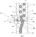
- the diverting mechanism 40 comprises a cylindrical block 80 extended along a vertical axis perpendicular to the lanes 20, 21 and positioned on the upper surface of the construction profile 800 of the automatic conveyor 3, at the connecting section 7.
- the cylindrical block 80 is configured to be controlled in rotation about its vertical axis so as to interface with the conveying devices 5 which transit at the connecting section 7.
- the cylindrical block comprises an open sector defined between its lower base and its upper base 80c, arranged to allow the passage of the test tubes supported by the conveying devices 5 which pass through the connecting section 7 and must overcome the cylindrical block 80 appropriately controlled in rotation.
- the lower base of the cylindrical block 80 is defined by two contact profiles 80a, 80b capable of alternately overlapping, depending on the rotation of the block 80, to one of the two side walls of the construction profile 800, substantially following in this way its shape to alternately assume said first or second diverting position, thereby realizing the appropriate routing of conveying devices 5 in transit, alternately, along the main lane 20 or the secondary lane 21.
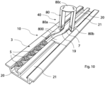
- Figures 10-12 illustrate the conveying devices 5 arriving from the main lane 20, and it is again the conformation of the construction profile 800 of the automatic conveyor 3 that creates an undulating section that results in a single transit lane 19 functional to bring the conveying devices 5 at the connecting section 7, and thus at the interfacing with the cylindrical block 80, in an equidistant position between the main lane 20 and the secondary lane 21. It is obvious that a completely mirror solution (not shown in the figures) wherein the conveying devices 5 all arrive from the secondary lane 21 is conceptually totally identical.
- the diverting mechanism 40 thus comprises again two contact profiles 80a, 80b spaced along opposite sides of the end part of the single transit lane 19 that flows into the connecting section 7.
- the contact profiles 80a, 80b are mutually connected by means of the upper base 80c of the cylindrical block 80.
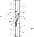
- the contact profiles 80a, 80b are simultaneously rotatable about the axis of rotation of the cylindrical block 80, to alternately assume the two positions (shown in Figures 11 , 12 ) able to laterally impact the conveying devices 5 to route them towards the main lane 20 or the secondary lane 21.
- a first contact profile 80a overlaps one of the two side walls of the construction profile 800 and does not come into contact with the conveying devices 5, while a second contact profile 80b overlaps the connecting section 7 and forces the conveying devices 5 to transit downstream of the cylindrical block 80 along the main lane 20.
- a second contact profile 80b overlaps the connecting section 7 and forces the conveying devices 5 to transit downstream of the cylindrical block 80 along the main lane 20.
- the second contact profile 80b overlaps one of the two side walls of the construction profile 800
- the first contact profile 80a overlaps the connecting section 7 and forces the connecting devices to transit downstream of the cylindrical block 80 along the secondary lane 21.
- the rotation of the cylindrical block 80 and thus of the contact profiles 80a, 80b can be activated by an actuator (not shown) of any known type, controlled by the central control unit E.
- the routing apparatus 10 by acting on conveying devices 5 that are located at a point equidistant between the two possible destination lanes, exhibits on them a thrust significantly less, if not even absent, with respect to the known solutions, limiting the phenomena of leakage of biological material from the eventual uncapped test tubes contained in the conveying devices themselves.
- routing apparatus 10 of the invention allows to limit the activations of mechanical parts with respect to the known solutions, preserving the components used from wear and from malfunctions or breakages.
Landscapes
- Chemical & Material Sciences (AREA)
- Physics & Mathematics (AREA)
- Health & Medical Sciences (AREA)
- Life Sciences & Earth Sciences (AREA)
- Analytical Chemistry (AREA)
- Biochemistry (AREA)
- General Health & Medical Sciences (AREA)
- General Physics & Mathematics (AREA)
- Immunology (AREA)
- Pathology (AREA)
- Chemical Kinetics & Catalysis (AREA)
- Branching, Merging, And Special Transfer Between Conveyors (AREA)
Applications Claiming Priority (1)
| Application Number | Priority Date | Filing Date | Title |
|---|---|---|---|
| IT102023000007287A IT202300007287A1 (it) | 2023-04-14 | 2023-04-14 | Apparato di instradamento di un dispositivo di trasporto di campioni biologici in un sistema di automazione di laboratorio |
Publications (2)
| Publication Number | Publication Date |
|---|---|
| EP4446748A2 true EP4446748A2 (de) | 2024-10-16 |
| EP4446748A3 EP4446748A3 (de) | 2024-10-23 |
Family
ID=87036364
Family Applications (1)
| Application Number | Title | Priority Date | Filing Date |
|---|---|---|---|
| EP24163756.0A Withdrawn EP4446748A3 (de) | 2023-04-14 | 2024-03-15 | Vorrichtung zum routen einer fördervorrichtung von biologischen proben in einem laborautomatisierungssystem |
Country Status (4)
| Country | Link |
|---|---|
| US (1) | US20250004000A1 (de) |
| EP (1) | EP4446748A3 (de) |
| CN (1) | CN118795166A (de) |
| IT (1) | IT202300007287A1 (de) |
Citations (2)
| Publication number | Priority date | Publication date | Assignee | Title |
|---|---|---|---|---|
| EP2780724B1 (de) | 2011-11-16 | 2016-03-23 | Inpeco Holding Ltd | Bearbeitungsstation für vorrichtungen zur förderung von behältern mit biologischen produkten |
| EP3129791B1 (de) | 2014-04-09 | 2018-07-11 | Inpeco Holding Ltd | Modifizierte vorrichtung zum transport eines behälters von biologischen produkten in einem laborautomatisierungssystem |
Family Cites Families (2)
| Publication number | Priority date | Publication date | Assignee | Title |
|---|---|---|---|---|
| US6024204A (en) * | 1997-11-14 | 2000-02-15 | Bayer Corporation | Conveyor system for clinical test apparatus |
| JP3839441B2 (ja) * | 2004-03-22 | 2006-11-01 | 株式会社アイディエス | 試験管搬送路の搬送方向変換装置 |
-
2023
- 2023-04-14 IT IT102023000007287A patent/IT202300007287A1/it unknown
-
2024
- 2024-03-15 EP EP24163756.0A patent/EP4446748A3/de not_active Withdrawn
- 2024-04-12 US US18/633,997 patent/US20250004000A1/en active Pending
- 2024-04-15 CN CN202410447569.6A patent/CN118795166A/zh active Pending
Patent Citations (2)
| Publication number | Priority date | Publication date | Assignee | Title |
|---|---|---|---|---|
| EP2780724B1 (de) | 2011-11-16 | 2016-03-23 | Inpeco Holding Ltd | Bearbeitungsstation für vorrichtungen zur förderung von behältern mit biologischen produkten |
| EP3129791B1 (de) | 2014-04-09 | 2018-07-11 | Inpeco Holding Ltd | Modifizierte vorrichtung zum transport eines behälters von biologischen produkten in einem laborautomatisierungssystem |
Also Published As
| Publication number | Publication date |
|---|---|
| US20250004000A1 (en) | 2025-01-02 |
| EP4446748A3 (de) | 2024-10-23 |
| CN118795166A (zh) | 2024-10-18 |
| IT202300007287A1 (it) | 2024-10-14 |
Similar Documents
| Publication | Publication Date | Title |
|---|---|---|
| CA2288620C (en) | High speed automated cog sorter | |
| JP6126617B2 (ja) | バイオ製品用容器を運搬するための装置のプロセスステーション | |
| EP1546736B1 (de) | Transfer- und positionierungsvorrichtung für ein automatisiertes förderbandsystem | |
| CN101918848B (zh) | 用来自动地识别、输送、及寻址生物材料样品的系统 | |
| EP4446748A2 (de) | Vorrichtung zum routen einer fördervorrichtung von biologischen proben in einem laborautomatisierungssystem | |
| US20040200190A1 (en) | Beverage bottling plant for filling bottles and like containers with a liquid beverage filling material and a conveyer arrangement for aligning and distributing packages containing filled bottles and like containers | |
| US20200324980A1 (en) | Transportation path diverter | |
| EP4448424B1 (de) | Vorrichtung und verfahren zum sortieren von behältern biologischer proben in einem automatisierungssystem eines analyselabors | |
| CN113573994B (zh) | 用于分拣容器的设施以及方法 | |
| WO2001072614A1 (en) | Apparatuses for the conveying, lifting and sorting of articles | |
| CN111372877B (zh) | 改道设备 | |
| CA2684310A1 (en) | Flow directions for a sorter bin | |
| FI131003B1 (en) | Cadence deviator for specimen carriers and method for cadencing specimen carriers | |
| ITPR20100071A1 (it) | Dispositivo di deviazione laterale di oggetti in movimento su una linea di trasporto | |
| NO317584B1 (no) | Anordning for utsortering av gjenstander |
Legal Events
| Date | Code | Title | Description |
|---|---|---|---|
| PUAI | Public reference made under article 153(3) epc to a published international application that has entered the european phase |
Free format text: ORIGINAL CODE: 0009012 |
|
| STAA | Information on the status of an ep patent application or granted ep patent |
Free format text: STATUS: THE APPLICATION HAS BEEN PUBLISHED |
|
| PUAL | Search report despatched |
Free format text: ORIGINAL CODE: 0009013 |
|
| AK | Designated contracting states |
Kind code of ref document: A2 Designated state(s): AL AT BE BG CH CY CZ DE DK EE ES FI FR GB GR HR HU IE IS IT LI LT LU LV MC ME MK MT NL NO PL PT RO RS SE SI SK SM TR |
|
| AK | Designated contracting states |
Kind code of ref document: A3 Designated state(s): AL AT BE BG CH CY CZ DE DK EE ES FI FR GB GR HR HU IE IS IT LI LT LU LV MC ME MK MT NL NO PL PT RO RS SE SI SK SM TR |
|
| RIC1 | Information provided on ipc code assigned before grant |
Ipc: G01N 35/04 20060101AFI20240913BHEP |
|
| STAA | Information on the status of an ep patent application or granted ep patent |
Free format text: STATUS: THE APPLICATION IS DEEMED TO BE WITHDRAWN |
|
| 18D | Application deemed to be withdrawn |
Effective date: 20250424 |