EP4445867A1 - Mundhöhlenreinigungsvorrichtung - Google Patents
Mundhöhlenreinigungsvorrichtung Download PDFInfo
- Publication number
- EP4445867A1 EP4445867A1 EP22904029.0A EP22904029A EP4445867A1 EP 4445867 A1 EP4445867 A1 EP 4445867A1 EP 22904029 A EP22904029 A EP 22904029A EP 4445867 A1 EP4445867 A1 EP 4445867A1
- Authority
- EP
- European Patent Office
- Prior art keywords
- nozzle
- oral cavity
- narrow portion
- sectional area
- washing liquid
- Prior art date
- Legal status (The legal status is an assumption and is not a legal conclusion. Google has not performed a legal analysis and makes no representation as to the accuracy of the status listed.)
- Pending
Links
Images


Classifications
-
- A—HUMAN NECESSITIES
- A61—MEDICAL OR VETERINARY SCIENCE; HYGIENE
- A61C—DENTISTRY; APPARATUS OR METHODS FOR ORAL OR DENTAL HYGIENE
- A61C17/00—Devices for cleaning, polishing, rinsing or drying teeth, teeth cavities or prostheses; Saliva removers; Dental appliances for receiving spittle
- A61C17/02—Rinsing or air-blowing devices, e.g. using fluid jets or comprising liquid medication
- A61C17/0202—Hand-pieces
-
- A—HUMAN NECESSITIES
- A61—MEDICAL OR VETERINARY SCIENCE; HYGIENE
- A61C—DENTISTRY; APPARATUS OR METHODS FOR ORAL OR DENTAL HYGIENE
- A61C17/00—Devices for cleaning, polishing, rinsing or drying teeth, teeth cavities or prostheses; Saliva removers; Dental appliances for receiving spittle
- A61C17/02—Rinsing or air-blowing devices, e.g. using fluid jets or comprising liquid medication
- A61C17/028—Rinsing or air-blowing devices, e.g. using fluid jets or comprising liquid medication with intermittent liquid flow
-
- A—HUMAN NECESSITIES
- A61—MEDICAL OR VETERINARY SCIENCE; HYGIENE
- A61M—DEVICES FOR INTRODUCING MEDIA INTO, OR ONTO, THE BODY; DEVICES FOR TRANSDUCING BODY MEDIA OR FOR TAKING MEDIA FROM THE BODY; DEVICES FOR PRODUCING OR ENDING SLEEP OR STUPOR
- A61M3/00—Medical syringes, e.g. enemata; Irrigators
- A61M3/02—Enemata; Irrigators
- A61M3/0279—Cannula; Nozzles; Tips; their connection means
Definitions
- the present disclosure relates to an oral cavity washing device.
- an oral cavity washing device including a device body including a pump that discharges a washing liquid and a nozzle that is provided in the device body and discharges the washing liquid discharged by the pump to the outside (see PTL 1).
- this oral cavity washing device for example, water or a washing liquid in which a medical agent is mixed with water is discharged from the nozzle toward an oral cavity, thereby removing food residues and dental plaques in the oral cavity.
- a narrow portion having an inner diameter set smaller than inner diameters of other portions may be provided in a nozzle.
- the narrow portion in the nozzle it is possible to change the liquid flow caused by, for example, the discharge amount, the discharge load, the flow speed, and the like of the washing liquid discharged from the nozzle, and to improve the performance of removing food residues and dental plaques.
- An object of the present disclosure is to provide an oral cavity washing device capable of changing a liquid flow of a washing liquid without increasing the number of parts.
- An oral cavity washing device includes a device body including a pump that discharges a washing liquid, and a nozzle that is provided in the device body and discharges the washing liquid discharged by the pump to an outside, wherein the nozzle includes a narrow portion in such a manner that the sectional area thereof is set to be smaller than that of another portion of the nozzle, and that the sectional area of the narrow portion is variable.
- an oral cavity washing device capable of changing a liquid flow of a washing liquid without increasing the number of parts.
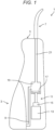
- FIG. 1 is a schematic view of oral cavity washing device 1 according to the first exemplary embodiment.
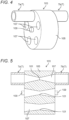
- Fig. 2 is an enlarged sectional view of a main part illustrating an example in which narrow portion 23 is formed by applying an external force to nozzle 7 of oral cavity washing device 1 according to the first exemplary embodiment.
- Fig. 3 is an enlarged sectional view of a main part illustrating another example in which narrow portion 23 is formed by applying an external force to nozzle 7 of oral cavity washing device 1 according to the first exemplary embodiment.
- Oral cavity washing device 1 includes tank 3, device body 5, and nozzle 7.
- Tank 3 stores therein, for example, water or a washing liquid obtained by mixing a medical agent with water.
- Tank 3 is detachably attached to device body 5.
- the washing liquid is supplied to the inside of tank 3 in a state where tank 3 is detached from device body 5.
- Tank 3 may be provided with a supply port therein through which the washing liquid can be supplied in a state where the tank is attached to device body 5.
- Tank 3 supplies the washing liquid stored in tank 3 to device body 5 in a state of being attached to device body 5.
- Device body 5 is formed in a housing shape larger than tank 3 so that tank 3 can be attached.
- Device body 5 is provided with a suction path 9 to which the washing liquid stored in tank 3 is supplied.
- Suction path 9 is provided with a filter (not illustrated) for removing foreign substances mixed in the washing liquid.
- Suction path 9 communicates with pump 11 built in device body 5, and supplies the washing liquid stored in tank 3 to pump 11 through driving of pump 11.
- Pump 11 includes motor 13, cam 15, piston 17, and pump chamber 19.
- Motor 13 is driven by supply of electric power from a rechargeable battery (not illustrated) accommodated inside device body 5.
- Cam 15 converts the rotation of motor 13 into an axial operating force.
- Piston 17 is reciprocated along a height direction of device body 5 by the axial operating force converted by cam 15.
- An end of piston 17 is disposed in pump chamber 19, and the volume thereof changes due to the reciprocating motion of piston 17.
- Pump chamber 19 communicates with suction path 9 and discharge path 21 provided inside device body 5.
- a suction valve (not illustrated) is provided between pump chamber 19 and suction path 9, and a discharge valve (not illustrated) is provided between pump chamber 19 and discharge path 21.
- pump 11 causes the washing liquid in tank 3 to flow into pump chamber 19 via suction path 9.
- the washing liquid flowing into pump chamber 19 is discharged to nozzle 7 via discharge path 21 when piston 17 moves in a direction of reducing the volume of pump chamber 19 through driving of motor 13.
- a power switch that turns on and off (ON/OFF) oral cavity washing device 1 is provided on an outer surface of device body 5.
- the outer surface of device body 5 is provided with an adjustment button for adjusting a liquid flow such as a discharge amount, a discharge load, and a flow speed of the washing liquid to be discharged from the nozzle.
- Nozzle 7 is formed in a hollow elongated shape, and is detachable from device body 5. An end of nozzle 7 close to device body communicates with discharge path 21 in a state of being attached to device body 5. Nozzle 7 sprays the washing liquid flowing out of discharge path 21 from the tip thereof. The washing liquid sprayed from nozzle 7 removes at least one selected from the group consisting of food residues and dental plaques in the oral cavity.
- such nozzle 7 is provided inside with narrow portion 23 having a sectional area set smaller than sectional areas of other portions.
- narrow portion 23 having a smaller sectional area is provided inside nozzle 7 having a cylindrical shape by setting the inner diameter to be smaller than other portions.
- Providing narrow portion 23 in nozzle 7 makes it possible to change a liquid flow such as, a discharge amount, a discharge load, and a flow speed of the washing liquid to be discharged. Changing the liquid flow of the washing liquid makes it possible to improve the removal performance for at least one selected from the group consisting of food residues and dental plaques in the oral cavity.
- a plurality of nozzles 7 having different sectional areas of narrow portion 23 can be replaced and used each time, but the number of parts increases.
- the sectional area of narrow portion 23 can be varied in one nozzle 7.
- Nozzle 7 is made of a material in which the shape thereof changes when an external force is applied, such as a plastically deformable resin, a plastically deformable metal, an ultraviolet curable resin, or a shape memory alloy.
- narrow portion 23 is formed by mechanically applying an external force from the outside to the inside of nozzle 7 using a jig or the like as indicated by the arrows to make its sectional area smaller than other portions.
- narrow portion 23 is mechanically stretched by applying an external force toward both sides in the length direction of nozzle 7 using a jig or the like as indicated by the arrows, and is formed to have a smaller sectional area than other portions.
- Narrow portion 23 may be formed by applying a chemical external force such as heat or ultraviolet rays in accordance with the material used for nozzle 7 to make its sectional area smaller than other portions and not limited by a mechanical external force.
- oral cavity washing device 1 includes device body 5 including pump 11 that discharges a washing liquid, and nozzle 7 that is provided in device body 5 and discharges the washing liquid discharged from pump 11 to the outside.
- Nozzle 7 has narrow portion 23 having a sectional area set to be smaller than sectional areas of other portions of nozzle 7. the sectional area being variable.
- the sectional area of narrow portion 23 can be changed, the liquid flow of the washing liquid to be discharged from nozzle 7 can be changed even with one nozzle 7 by changing the sectional area of narrow portion 23.
- the liquid flow of the washing liquid can be changed without increasing the number of parts.
- the sectional area of narrow portion 23 is changed by using an external force.
- adjusting the external force makes it possible to adjust the sectional area of narrow portion 23 in accordance with the liquid flow of the washing liquid.
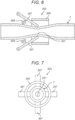
- FIG. 4 is an enlarged perspective view of a main part of nozzle 7 of oral cavity washing device 1 according to the second exemplary embodiment.
- Fig. 5 is an enlarged sectional view of the main part of nozzle 7 of oral cavity washing device 1 according to the second exemplary embodiment.
- narrow portion 101 includes selector 103 formed with a plurality of different sectional areas.
- nozzle 7 is divided into a portion on the suction side and a portion on the discharge side of the washing liquid.
- the portion on the suction side is denoted by reference numeral "7a”.
- the portion on the discharge side is denoted by reference numeral "7b”.
- the portion on the suction side and the portion on the discharge side of the washing liquid denoted by reference numerals "7a” and "7b", respectively, are referred to as divided nozzles 7a, 7b.
- Narrow portion 101 is disposed between divided nozzles 7a, 7b.
- Narrow portion 101 includes selector 103.
- Selector 103 includes base 105 and a plurality of communication holes 107.
- Base 105 is formed in an annular shape and is disposed between divided nozzles 7a, 7b.
- shaft 109 integrally formed with base 105 is formed so as to protrude toward nozzles 7a, 7b. That is, shaft 109 protrudes in the dividing direction of nozzle 7. In other words, shaft 109 protrudes in the left-right directions in Figs. 4 and 5 .
- Shaft 109 is pivotally supported by a support (not illustrated) formed integrally with divided nozzles 7a, 7b.
- base 105 is rotatably disposed between divided nozzles 7a, 7b.
- a seal member (not illustrated) seals between base 105 and divided nozzles 7a, 7b.
- the plurality of communication holes 107 penetrate base 105 in an axial direction.
- the sectional areas of the openings on both sides of each communication hole 107 are set to be equal to the sectional areas of divided nozzles 7a, 7b.
- the plurality of (here, six) communication holes 107 are disposed at equal intervals in the circumferential direction of base 105.
- Narrow portion 101 formed with a sectional area smaller than the sectional areas of the openings on both sides is provided at a central portion of each communication hole 107.
- Narrow portions 101 of the plurality of communication holes 107 have different sectional areas from each other.
- narrow portion 101 includes selector 103 formed with a plurality of different sectional areas.
- selector 103 formed with a plurality of different sectional areas.
- FIG. 6 is an enlarged sectional view of a main part of nozzle 7 of oral cavity washing device 1 according to the third exemplary embodiment.
- Fig. 7 is a front view of Fig. 6 .
- Fig. 8 is an enlarged sectional view of the main part of nozzle 7 of oral cavity washing device 1 according to the third exemplary embodiment.
- Fig. 9 is a front view of Fig. 8 .
- narrow portion 201 includes variable portion 203 that changes a sectional area from the outside of nozzle 7.
- the suction side and discharge side of nozzle 7 for the washing liquid are formed of a hard material, for example, resin, metal, or the like.
- a portion located between the suction side and the discharge side of nozzle 7 is formed of a soft material, for example, resin, metal, or the like.
- Narrow portion 201 is disposed in a portion formed of a soft material.
- Narrow portion 201 includes variable portion 203.
- Variable portion 203 includes tubular member 205 and at least one pressing member 207.
- At least one pressing member 207 may include two or more pressing members 207.
- Nozzle 7 is inserted into tubular member 205.
- Tubular member 205 is supported in a radial direction via a support (not illustrated) integrally provided on the outer periphery of nozzle 7.
- Tubular member 205 is disposed so as to be movable in a length direction of nozzle 7 on the outer periphery of nozzle 7 via the support.
- Pressing member 207 is formed in a plate shape.
- One end in a length direction of pressing member 207 is pivotally supported via a pivot support (not illustrated) integrally provided on the outer periphery of nozzle 7.
- the other end in the length direction of pressing member 207 moves in a direction away from the outer periphery of nozzle 7 and in a direction approaching the outer periphery of nozzle 7.
- the other end in the length direction of pressing member 207 moves in one of a direction away from the outer periphery of nozzle 7 and a direction approaching the outer periphery of nozzle 7.
- One end in the length direction of pressing member 207 is disposed at a position farther from the outer periphery of nozzle 7 than the other end in the length direction.
- Bias member 209 that biases pressing member 207 in a direction away from the outer periphery of nozzle 7 is disposed between one end side in the length direction of pressing member 207 and the outer periphery of nozzle 7.
- the other end in the length direction of pressing member 207 is disposed inside tubular member 205 and abuts on a portion of nozzle 7 formed of a soft material.
- the plurality of (here, four) pressing members 207 are disposed at equal intervals in the circumferential direction with respect to the outer periphery of nozzle 7.
- pressing member 207 presses the outer periphery of nozzle 7 when tubular member 205 abuts on pressing member 207.
- Narrow portion 201 having a smaller sectional area than other portions is formed in nozzle 7 by pressing with pressing member 207.
- the abutment with pressing member 207 is strengthened, and pressing member 207 further presses the outer periphery of nozzle 7. Further pressing of pressing member 207 reduces the sectional area of narrow portion 201.
- the sectional area of narrow portion 201 can be changed from the outside of nozzle 7 via pressing member 207 by the movement of tubular member 205.
- adjusting the position of tubular member 205 makes it possible to adjust the sectional area of narrow portion 201 in accordance with the liquid flow of the washing liquid.
- tubular member 205 may be moved, and for example, a jig may be inserted into nozzle 7.
- variable portion 203 of nozzle 7 When the portion to be deformed by variable portion 203 of nozzle 7 is formed of a plastically deformable material, the sectional area of narrow portion 201 can be maintained, and thus variable portion 203 can be configured to be detachable from nozzle 7.
- the portion of nozzle 7 to be deformed by variable portion 203 may be formed of a restorable material such as an elastic body. In this case, the reduced sectional area of narrow portion 201 can be increased by the movement of tubular member 205.
- narrow portion 201 includes variable portion 203 that changes a sectional area from the outside of nozzle 7.
- adjusting variable portion 203 makes it possible to adjust the sectional area of narrow portion 201 with one nozzle 7 according to the liquid flow of the washing liquid.
- the sectional shape of the inside of nozzle 7 is circular.
- the term “circular” includes “elliptical".
- the sectional shape of the inside of nozzle 7 is not limited to a circular shape.
- the sectional shape of the inside of nozzle 7 may be a polygonal shape such as a triangle, a quadrangle, or a pentagon.
- the sectional shape of the inner surface of nozzle 7 may be a non-circular shape. That is, when the sectional shape is circular, the sectional area is changed by changing the inner diameter of nozzle 7.
- the sectional area can be changed by changing at least one of the major axis (that is, the long axis) and the minor axis (that is, the short axis) of the ellipse.
- the sectional shape is a polygon such as a quadrangle
- the sectional area can be changed by deforming at least one of the plurality of wall surfaces constituting the inner surface so as to change the distance between the one surface and another surface (for example, a surface facing the one surface).
- the present disclosure is applicable to an oral cavity washing device that discharges liquid from a nozzle.
Landscapes
- Health & Medical Sciences (AREA)
- Life Sciences & Earth Sciences (AREA)
- Veterinary Medicine (AREA)
- Public Health (AREA)
- General Health & Medical Sciences (AREA)
- Animal Behavior & Ethology (AREA)
- Epidemiology (AREA)
- Dentistry (AREA)
- Hematology (AREA)
- Heart & Thoracic Surgery (AREA)
- Biomedical Technology (AREA)
- Anesthesiology (AREA)
- Engineering & Computer Science (AREA)
- Brushes (AREA)
- Nozzles (AREA)
- Dental Tools And Instruments Or Auxiliary Dental Instruments (AREA)
Applications Claiming Priority (2)
| Application Number | Priority Date | Filing Date | Title |
|---|---|---|---|
| JP2021198432A JP2023084321A (ja) | 2021-12-07 | 2021-12-07 | 口腔内洗浄装置 |
| PCT/JP2022/043277 WO2023106098A1 (ja) | 2021-12-07 | 2022-11-24 | 口腔内洗浄装置 |
Publications (2)
| Publication Number | Publication Date |
|---|---|
| EP4445867A1 true EP4445867A1 (de) | 2024-10-16 |
| EP4445867A4 EP4445867A4 (de) | 2025-03-26 |
Family
ID=86730349
Family Applications (1)
| Application Number | Title | Priority Date | Filing Date |
|---|---|---|---|
| EP22904029.0A Pending EP4445867A4 (de) | 2021-12-07 | 2022-11-24 | Mundhöhlenreinigungsvorrichtung |
Country Status (5)
| Country | Link |
|---|---|
| US (1) | US20250025272A1 (de) |
| EP (1) | EP4445867A4 (de) |
| JP (1) | JP2023084321A (de) |
| CN (1) | CN118265501A (de) |
| WO (1) | WO2023106098A1 (de) |
Family Cites Families (10)
| Publication number | Priority date | Publication date | Assignee | Title |
|---|---|---|---|---|
| JP2540204Y2 (ja) * | 1991-08-20 | 1997-07-02 | リコーエレメックス株式会社 | 液体付勢装置 |
| JP2540207Y2 (ja) * | 1991-09-24 | 1997-07-02 | リコーエレメックス株式会社 | 液体付勢装置 |
| JPH09285477A (ja) * | 1996-04-23 | 1997-11-04 | Taisei Plus Kk | 歯間洗浄器及びその収納ケース |
| US7258285B1 (en) * | 2005-01-14 | 2007-08-21 | Elkhart Brass Manufacturing Company, Inc. | Adjustable smooth bore nozzle |
| CN107072759A (zh) * | 2014-10-29 | 2017-08-18 | 皇家飞利浦有限公司 | 用于提供各种液体/空气输出流模式的可调整的组件和喷嘴 |
| JP7029704B2 (ja) | 2016-11-18 | 2022-03-04 | パナソニックIpマネジメント株式会社 | 口腔洗浄装置 |
| JP7065365B2 (ja) * | 2017-02-07 | 2022-05-12 | パナソニックIpマネジメント株式会社 | 口腔洗浄装置およびそのノズル |
| JP7203338B2 (ja) * | 2019-01-21 | 2023-01-13 | パナソニックIpマネジメント株式会社 | 口腔洗浄装置 |
| CN210687043U (zh) * | 2019-09-05 | 2020-06-05 | 广东广顺新能源动力科技有限公司 | 一种具有多种口径的轮盘式节流阀 |
| KR102761031B1 (ko) * | 2019-10-29 | 2025-01-31 | 삼성중공업 주식회사 | 배관계의 유량조절설비 |
-
2021
- 2021-12-07 JP JP2021198432A patent/JP2023084321A/ja active Pending
-
2022
- 2022-11-24 US US18/709,411 patent/US20250025272A1/en active Pending
- 2022-11-24 WO PCT/JP2022/043277 patent/WO2023106098A1/ja not_active Ceased
- 2022-11-24 EP EP22904029.0A patent/EP4445867A4/de active Pending
- 2022-11-24 CN CN202280076373.XA patent/CN118265501A/zh active Pending
Also Published As
| Publication number | Publication date |
|---|---|
| EP4445867A4 (de) | 2025-03-26 |
| CN118265501A (zh) | 2024-06-28 |
| US20250025272A1 (en) | 2025-01-23 |
| JP2023084321A (ja) | 2023-06-19 |
| WO2023106098A1 (ja) | 2023-06-15 |
Similar Documents
| Publication | Publication Date | Title |
|---|---|---|
| JP7203338B2 (ja) | 口腔洗浄装置 | |
| US11844916B2 (en) | Ear irrigation device | |
| JP5468002B2 (ja) | 使い捨て式歯科ハンドピース | |
| US10799891B2 (en) | Compact linear oscillating water jet | |
| KR100438607B1 (ko) | 파워브러쉬를 구비한 진공청소기의 흡입헤드 | |
| US9731303B2 (en) | Oscillating nozzles | |
| EP4445867A1 (de) | Mundhöhlenreinigungsvorrichtung | |
| JP2018131946A (ja) | チューブポンプおよび保持機構 | |
| US11751899B2 (en) | Differential pressure motor and method for operating a differential pressure motor | |
| US7686022B2 (en) | Nozzle device, and cleaning apparatus equipped with the nozzle device | |
| EP4302671A1 (de) | Geschirrspülmaschine | |
| JP4648623B2 (ja) | 振り子式往復鋸装置 | |
| WO2021152048A1 (en) | Tool for a dental treatment, transducer for such a tool and method for assembling such a tool | |
| CN108714493A (zh) | 一种间歇出水的出水装置 | |
| KR101631613B1 (ko) | 버블발생기 | |
| JP4478032B2 (ja) | 除毛装置 | |
| CN110860388B (zh) | 出水装置和花洒 | |
| CN222970054U (zh) | 出水模块以及应用其的出水装置 | |
| KR100483001B1 (ko) | 공기식 공구 | |
| CN223628786U (zh) | 一种多档位出水装置 | |
| CN220876974U (zh) | 一种可调喷嘴 | |
| JP4733867B2 (ja) | 往復動ポンプのストローク量調整装置 | |
| KR200304107Y1 (ko) | 공기식 공구 | |
| JP2014528550A (ja) | 高圧洗浄器具用ピストンポンプ | |
| JP7221705B2 (ja) | スプレーガン |
Legal Events
| Date | Code | Title | Description |
|---|---|---|---|
| STAA | Information on the status of an ep patent application or granted ep patent |
Free format text: STATUS: THE INTERNATIONAL PUBLICATION HAS BEEN MADE |
|
| PUAI | Public reference made under article 153(3) epc to a published international application that has entered the european phase |
Free format text: ORIGINAL CODE: 0009012 |
|
| STAA | Information on the status of an ep patent application or granted ep patent |
Free format text: STATUS: REQUEST FOR EXAMINATION WAS MADE |
|
| 17P | Request for examination filed |
Effective date: 20240514 |
|
| AK | Designated contracting states |
Kind code of ref document: A1 Designated state(s): AL AT BE BG CH CY CZ DE DK EE ES FI FR GB GR HR HU IE IS IT LI LT LU LV MC ME MK MT NL NO PL PT RO RS SE SI SK SM TR |
|
| DAV | Request for validation of the european patent (deleted) | ||
| DAX | Request for extension of the european patent (deleted) | ||
| A4 | Supplementary search report drawn up and despatched |
Effective date: 20250224 |
|
| RIC1 | Information provided on ipc code assigned before grant |
Ipc: A61C 17/02 20060101AFI20250218BHEP |