EP4445862A2 - Anzeigesystem für eine chirurgische beleuchtungsvorrichtung - Google Patents
Anzeigesystem für eine chirurgische beleuchtungsvorrichtung Download PDFInfo
- Publication number
- EP4445862A2 EP4445862A2 EP24197061.5A EP24197061A EP4445862A2 EP 4445862 A2 EP4445862 A2 EP 4445862A2 EP 24197061 A EP24197061 A EP 24197061A EP 4445862 A2 EP4445862 A2 EP 4445862A2
- Authority
- EP
- European Patent Office
- Prior art keywords
- illumination
- indication
- light modules
- light
- output
- Prior art date
- Legal status (The legal status is an assumption and is not a legal conclusion. Google has not performed a legal analysis and makes no representation as to the accuracy of the status listed.)
- Granted
Links
Images


Classifications
-
- G—PHYSICS
- G06—COMPUTING OR CALCULATING; COUNTING
- G06V—IMAGE OR VIDEO RECOGNITION OR UNDERSTANDING
- G06V10/00—Arrangements for image or video recognition or understanding
- G06V10/40—Extraction of image or video features
- G06V10/60—Extraction of image or video features relating to illumination properties, e.g. using a reflectance or lighting model
-
- A—HUMAN NECESSITIES
- A61—MEDICAL OR VETERINARY SCIENCE; HYGIENE
- A61B—DIAGNOSIS; SURGERY; IDENTIFICATION
- A61B90/00—Instruments, implements or accessories specially adapted for surgery or diagnosis and not covered by any of the groups A61B1/00 - A61B50/00, e.g. for luxation treatment or for protecting wound edges
- A61B90/30—Devices for illuminating a surgical field, the devices having an interrelation with other surgical devices or with a surgical procedure
-
- A—HUMAN NECESSITIES
- A61—MEDICAL OR VETERINARY SCIENCE; HYGIENE
- A61B—DIAGNOSIS; SURGERY; IDENTIFICATION
- A61B90/00—Instruments, implements or accessories specially adapted for surgery or diagnosis and not covered by any of the groups A61B1/00 - A61B50/00, e.g. for luxation treatment or for protecting wound edges
- A61B90/36—Image-producing devices or illumination devices not otherwise provided for
- A61B90/361—Image-producing devices, e.g. surgical cameras
-
- G—PHYSICS
- G06—COMPUTING OR CALCULATING; COUNTING
- G06N—COMPUTING ARRANGEMENTS BASED ON SPECIFIC COMPUTATIONAL MODELS
- G06N3/00—Computing arrangements based on biological models
- G06N3/02—Neural networks
- G06N3/04—Architecture, e.g. interconnection topology
- G06N3/0464—Convolutional networks [CNN, ConvNet]
-
- G—PHYSICS
- G06—COMPUTING OR CALCULATING; COUNTING
- G06N—COMPUTING ARRANGEMENTS BASED ON SPECIFIC COMPUTATIONAL MODELS
- G06N3/00—Computing arrangements based on biological models
- G06N3/02—Neural networks
- G06N3/08—Learning methods
- G06N3/09—Supervised learning
-
- G—PHYSICS
- G06—COMPUTING OR CALCULATING; COUNTING
- G06V—IMAGE OR VIDEO RECOGNITION OR UNDERSTANDING
- G06V10/00—Arrangements for image or video recognition or understanding
- G06V10/70—Arrangements for image or video recognition or understanding using pattern recognition or machine learning
- G06V10/82—Arrangements for image or video recognition or understanding using pattern recognition or machine learning using neural networks
-
- A—HUMAN NECESSITIES
- A61—MEDICAL OR VETERINARY SCIENCE; HYGIENE
- A61B—DIAGNOSIS; SURGERY; IDENTIFICATION
- A61B34/00—Computer-aided surgery; Manipulators or robots specially adapted for use in surgery
- A61B34/20—Surgical navigation systems; Devices for tracking or guiding surgical instruments, e.g. for frameless stereotaxis
- A61B2034/2046—Tracking techniques
- A61B2034/2048—Tracking techniques using an accelerometer or inertia sensor
-
- A—HUMAN NECESSITIES
- A61—MEDICAL OR VETERINARY SCIENCE; HYGIENE
- A61B—DIAGNOSIS; SURGERY; IDENTIFICATION
- A61B34/00—Computer-aided surgery; Manipulators or robots specially adapted for use in surgery
- A61B34/25—User interfaces for surgical systems
-
- G—PHYSICS
- G06—COMPUTING OR CALCULATING; COUNTING
- G06N—COMPUTING ARRANGEMENTS BASED ON SPECIFIC COMPUTATIONAL MODELS
- G06N3/00—Computing arrangements based on biological models
- G06N3/02—Neural networks
- G06N3/08—Learning methods
-
- Y—GENERAL TAGGING OF NEW TECHNOLOGICAL DEVELOPMENTS; GENERAL TAGGING OF CROSS-SECTIONAL TECHNOLOGIES SPANNING OVER SEVERAL SECTIONS OF THE IPC; TECHNICAL SUBJECTS COVERED BY FORMER USPC CROSS-REFERENCE ART COLLECTIONS [XRACs] AND DIGESTS
- Y02—TECHNOLOGIES OR APPLICATIONS FOR MITIGATION OR ADAPTATION AGAINST CLIMATE CHANGE
- Y02B—CLIMATE CHANGE MITIGATION TECHNOLOGIES RELATED TO BUILDINGS, e.g. HOUSING, HOUSE APPLIANCES OR RELATED END-USER APPLICATIONS
- Y02B20/00—Energy efficient lighting technologies, e.g. halogen lamps or gas discharge lamps
- Y02B20/40—Control techniques providing energy savings, e.g. smart controller or presence detection
Definitions
- the present disclosure relates to an indication system for a surgical lighting apparatus.
- the disclosure relates to an indication system comprising a computer device connectable to a plurality of light modules.
- the disclosure further relates to a system for determining overlap of illumination zones of surgical lighting apparatus.
- Surgical lights are used in operating rooms to illuminate the field of surgery.
- IEC60601-2-41 states that total irradiance should be minimized, that the total irradiance in the lighted area should not exceed a specified amount, that it is possible to exceed that irradiance amount if the user overlaps light fields of several luminaires such as light modules, and that this information should be included in the instructions for use (IFU), so that users can act accordingly. This creates certain tasks and obligations on the user. It is desired to further aid the user in such.
- the present disclosure provides an indication system for a surgical lighting apparatus, a surgical lighting apparatus, and a method of indication, as defined in the appended claims, to which reference should now be made.
- an indication system for a surgical lighting apparatus comprises a computer device connectable to a plurality of light modules.
- the computer device is configured to: determine an illumination setting for each of the plurality of light modules; compare the illumination settings of at least two of the plurality of light modules to at least one output illumination threshold; and, output an indication if the at least one output illumination threshold is exceeded.
- the indication system of the present disclosure draws additional attention to the information, but only if the at least one output illumination threshold is exceeded.
- the indication system provides guided interaction between the user and the indication system, and is efficient as the indication system only draws additional attention when a threshold is exceeded.
- the computer device is configured to: if the plurality of light modules comprises more than two light modules, determine the two of the plurality of light modules having the two highest illumination settings. By determining the two light modules having the two highest illumination settings, it may be determined, using only the illumination settings of these two light modules, whether at least one output illumination threshold is exceeded. This provides improved computational efficiency and prevents unnecessary indications.
- the step of comparing the illumination settings of at least two of the plurality of light modules to at least one output illumination threshold may comprise: combining the illumination settings of the at least two of the plurality of light modules, or of the two of the plurality of light modules having the two highest illumination settings, and comparing the combined illumination setting to a total output illumination threshold.
- the illumination setting for each of the plurality of light modules may be a percentage of maximum illumination of the light module, e.g. 50 % of maximum illumination, or it may be a set power (e.g. irradiance) of the light module, e.g. 160 kilolux (klx) or 615 W per m 2 .
- the total output illumination threshold may be a percentage of a total illumination setting of the light modules.
- the total output illumination threshold may be 160% of the maximum illumination of each light module, e.g. two light modules each set to an illumination setting of 80%.
- the total output illumination threshold may be an irradiance, such as 256 klx, or 260 klx, or 180 klx, or 205 klx.
- the computer device may be configured to convert a determined illumination setting to a different unit, so that the determined illumination setting and the output illumination threshold align. For example, if the illumination setting for each of the plurality of light modules is determined as a percentage of maximum illumination of the light module, and the threshold is an irradiance, the computer device may convert the percentage of maximum illumination to an irradiance, and vice versa.
- the step of comparing the illumination settings of at least two of the plurality of light modules to at least one output illumination threshold may comprise: comparing an illumination setting of a first one of the plurality of light modules to a first output illumination threshold, and an illumination setting of a second one of the plurality of light modules to a second, dynamic, output illumination threshold, the second threshold being dependent on at least one of the first threshold and the first illumination setting.
- the first one and the second one of the plurality of light modules may be the two of the plurality of light modules having the two highest illumination settings.
- the computer device may be configured to determine whether an illumination zone of one of the plurality of light modules overlaps with an illumination zone of another one of the plurality of light modules.
- the computer device may be configured: not to output the indication if the illumination zones do not overlap; and/or to output a further indication if the illumination zones do overlap and the output illumination threshold is exceeded; and/or to output the indication only if the illumination zones overlap.
- the computer device may be configured to continually determine if the illumination zones overlap. This allows for up-to-date indications to be provided.
- the computer device may be configured to determine if the illumination zones overlap at predetermined time intervals.
- the predetermined time interval may be between 1 second and 1 minute, or between 1 second and 10 seconds, or between 1 second and 5 seconds. Increasing the time interval may reduce the computational burden, and therefore increase the efficiency of the system.
- the computer device may be configured to determine a percentage overlap if the illumination zones overlap. Such a percentage overlap may help in providing an indication only when required. That is, an indication may only be provided if the overlap exceeds e.g. 5%, or 10%, or 20%, or 30%, or any other suitable value.
- each one of the plurality of light modules comprises at least one of: a structured light system, and the step of determining whether the illumination zones overlap comprises detecting an interference pattern of structured light of the structured light systems; and a camera, and the step of determining whether the illumination zones overlap comprises comparing images of each of the cameras for corresponding features.
- the illumination zones are considered to overlap if either the interference pattern of structured light, or corresponding features of the camera images, are within each of the respective illumination zones. This allows for efficient detecting of overlapping illumination zones, including a percentage of overlap if required, using relatively simple structured light systems, or widely available cameras, such as standard RGB cameras using a CCD or CMOS sensor.
- the computer device further comprises an artificial neural network, configured using a training set of data, wherein: the step of detecting the interference pattern comprising using the artificial neural network to detect the interference pattern of the structured light; and/or the step of comparing images of each of the cameras for feature detection comprises using the artificial neural network to detect corresponding features in images of different cameras.
- an artificial neural network allows for improved detecting of overlap.
- the system comprising cameras and structured light systems, and the artificial neural network being used to detect interference patterns and corresponding features, may further improve detecting of overlap.
- the artificial neural network may be configured to receive and process context-sensitive information based on at least one of: a patient characteristic; a surgery type; environmental data; and illumination settings, and/or focus settings, of the at least two light modules.
- context-sensitive processing allows for e.g. an output illumination threshold to be dynamic, based on at least one patient characteristic (e.g. a lower threshold based on the patient body type and/or skin pigmentation), on surgery type (e.g. a higher threshold based on the specific surgical procedure), or on other data.
- the computer device may be configured to prevent an illumination setting of one of the plurality of light modules being changed until the indication has been acknowledged.
- the computer device may be configured to automatically reduce an illumination setting of one of the plurality of light modules if the at least one output illumination threshold is exceeded.
- the illumination setting may be automatically reduced only after the at least one output illumination threshold is exceeded for a predetermined period of time and/or by a predetermined illumination setting amount and/or upon the indication not being acknowledged within a predetermined period of time.
- the illumination settings of at least two of the plurality of light modules are compared to at least one output illumination threshold before determining if the illumination zones of light modules overlap.
- the determination of an overlap may only be performed if the output illumination threshold is exceeded.
- each one of the plurality of light modules may comprise at least one of: a position sensor; an angle sensor; an accelerometer; and a gyroscope, for determining whether an illumination zone of one of the plurality of light modules overlaps with an illumination zone of another one of the plurality of light modules.
- the system determines the position and orientation of each light module relative to each of the other light modules to determine whether an illumination zone of one of the plurality of light modules overlaps with an illumination zone of another one of the plurality of light modules.
- the computer device may be connected to a camera system, the camera system comprising at least two cameras for determine a position and an angle of each one of the plurality of light modules, and a position of the illumination zones of each one of the plurality of light modules, for determining whether an illumination zone of one of the plurality of light modules overlaps with an illumination zone of another one of the plurality of light modules.
- the indication system comprises an indicator.
- the indication may be output by activating the indicator.
- the indicator may be a visual indicator and/or an audible indicator.
- the indication is output on at least one of: one of the plurality of light modules; a wall control panel; a mobile controller; and a third party device.
- the indication is at least one of a visual indication; and an audible indication. This may allow for an indication to be output clearly, and for it to be quickly received, by a user.
- one of, or each of, the light modules may comprise indicia to display the indication.
- an indication may be displayed by illuminating the indicia.
- the indicia may be illuminated in specific colour.
- the colour may be a colour that makes the indication noticeable, e.g. red, yellow or orange.
- each of the plurality of light modules comprises a light module control panel which comprises the indicia.
- the wall control panel may comprise a Graphical User Interface (GUI).
- GUI Graphical User Interface
- the indication may be output within the GUI.
- the mobile controller may comprise a, or the, Graphical User Interface (GUI).
- the indication may comprise context-sensitive information such as at least one of: a patient characteristic; surgery type; environmental data; and illumination settings, and/or focus settings, of the at least two light modules.
- context-sensitive information such as at least one of: a patient characteristic; surgery type; environmental data; and illumination settings, and/or focus settings, of the at least two light modules.
- context-sensitive information may provide for improved and/or guided human-machine interaction and may allow the user to easily see relevant context-sensitive information.
- the computer device may be configured to receive at least one of: inputs for acknowledging the indication; inputs for putting the indication system on hold; and inputs for pausing the indication.
- the inputs for putting the indication on hold may comprise an amount time to put the indication system on hold, or an event to trigger reactivation of the indication system.
- the event may be: changing the light module output illumination setting; or the detection of movement of the light module.
- the inputs for delaying the indication may comprise an amount of time to delay the indication, or an event to trigger release of the indication.
- the event may be: changing the light module output illumination setting; or the detection of movement of the light module.
- the indication may be "paused" only after it has been activated, whereas the indication system may be put on hold at any time.
- Such inputs allow for a more efficient indication system in which a user may interact with the indication in a number of improved ways.
- the computer device may be configured to receive an input for increasing and/or decreasing an illumination setting of one of, or each of, the plurality of light modules. At least one of the light modules, the wall control panel, and the GUI may comprise inputs for providing the input for increasing and/or decreasing the illumination setting.
- the computer device may be configured to, each time an illumination setting of one of the plurality of light modules is modified, compare the illumination settings of at least two of the plurality of light modules to at least one output illumination threshold.
- the computer device may comprise a processor and memory.
- the memory may store instructions which, when executed by the processor, enable the indication system to carry out the steps it is configured to execute. If the computer device does not comprise memory, the computer device may be a thin client connected to a server, wherein the server stores the instructions.
- a surgical lighting apparatus comprising: an indication system substantially as described herein; and a plurality of light modules connected to the computer device.
- the surgical lighting apparatus comprises a controller configured to receive an input for increasing and/or decreasing an illumination setting of one of, or each of, the plurality of light modules, said controller being further configured to communicate said input to said computer device of said indication system.
- the controller may be configured to receive said input for increasing and/or decreasing an illumination setting from said inputs.
- each of the at least two light modules comprises a structured light camera connected to the computer device.
- a method of indication for a surgical lighting apparatus comprising a plurality of light modules, comprising: determining an illumination setting for each of the plurality of light modules; comparing the illumination settings of at least two of the plurality of light modules to at least one output illumination threshold; and, outputting an indication if the at least one output illumination threshold is exceeded.
- the method may comprise the step of: if the plurality of light modules comprises more than two light modules, determining the two of the plurality of light modules having the two highest illumination settings.
- the method may comprise the step of: combining the illumination settings of the at least two of the plurality of light modules, or the two of the plurality of light modules having the two highest illumination settings, and comparing the combined illumination setting to a total output illumination threshold.
- the method may comprise the step of: comparing an illumination setting of a first one of the plurality of light modules to a first output illumination threshold, and an illumination setting of a second one of the plurality of light modules to a second, dynamic, output illumination threshold, the second threshold being dependent on at least one of the first threshold and the first illumination setting.
- the first one and the second one of the plurality of light modules may be the two of the plurality of light modules having the two highest illumination settings.
- the method may comprise the step of: determining whether an illumination zone of one of the plurality of light modules overlaps with an illumination zone of another one of the plurality of light modules.
- determining whether the illumination zones overlap may comprise using structured light systems of the plurality of light modules to detect an interference pattern of structured light of the structure light systems.
- determining whether the illumination zones overlap may comprise using cameras of the plurality of light modules to detect corresponding features in images of different cameras.
- the step of detecting the interference pattern and/or the step of detecting corresponding features in images of different cameras comprises using an artificial neural network, configured using a training set of data. If both cameras and structured light systems/cameras are used, and the artificial neural network is used in detecting both the interference patterns and corresponding features, detection performance may be improved.
- using the artificial neural network comprises context-sensitive processing based on at least one of: a patient characteristic; surgery type; environmental data; and illumination settings, and/or focus settings, of the at least two light modules.
- the step of determining whether an illumination zone of one of the plurality of light modules overlaps with an illumination zone of another one of the plurality of light modules may be achieved using position sensors, angle sensors, accelerometers, and gyroscopes. Alternatively, this may be achieved using a camera system for determine a position and angle of each of the plurality of light modules.
- the method may comprise at least one step of: preventing outputting the indication if the illumination zones do not overlap; outputting a further indication if the illumination zones do overlap and the output illumination threshold is exceeded; and outputting the indication only if the illumination zones overlap.
- a detection system for a lighting apparatus comprising: a computer device connectable to a plurality of light modules, wherein the computer device is configured to: determine whether an illumination zone of one of the plurality of light modules overlaps with an illumination zone of another one of the plurality of light modules.
- each one of the plurality of light modules comprises a structured light system
- the computer device is configured to determine whether the illumination zones overlap comprises detecting an interference pattern of structured light of the structure light systems.
- the detection system comprises at least two cameras, wherein the step of determining whether the illumination zones overlap comprises comparing images of each of the cameras for corresponding features.
- the at least two cameras may be provided in respective ones of the plurality of light modules.
- each light module comprises a camera.
- the illumination zones are considered to overlap if the corresponding features of the camera images are within each of the respective illumination zones.
- the computer device may be configured to determine a percentage overlap if the illumination zones overlap.
- the step of detecting the interference pattern comprises using an artificial neural network, configured using a training set of data.
- the plurality of light modules may comprise at least one of a position sensor, an angle sensor, an accelerometer, and a gyroscope, for determining whether an illumination zone of one of the plurality of light modules overlaps with an illumination zone of another one of the plurality of light modules.
- the computer device may be connected to a camera system, the camera system comprising at least two cameras for determine a position and an angle of each of the plurality of light modules, and a position of the illumination zones, for determining whether an illumination zone of one of the plurality of light modules overlaps with an illumination zone of another one of the plurality of light modules.
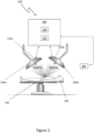
- Figure 1 shows a schematic illustration of an indication system 100 for a surgical lighting apparatus.
- the surgical lighting apparatus is configured to illuminate a surgery site on a patient 102 disposed on a patient support apparatus 103.
- the indication system 100 is in communication with the surgical lighting apparatus which comprises two light modules 104a, 104b. However, it will be appreciated that the surgical lighting apparatus may comprise three, four, or more such light modules.
- the indication system 100 comprises a computer device 106 which is connectable to the two light modules 104a, 104b. The connection between the computer device 106 and the light modules 104a, 104b may be wireless or wired.
- the computer device 106 is configured to receive, or determine, the output illumination setting of each light module 104a, 104b, in the surgical lighting apparatus.
- the computer device 106 of the indication system 100 may be a standalone computer device, i.e. a device that is independent from other parts of the surgical lighting apparatus.
- the computer device 106 may be integral to one of the two light modules 104a, 104b, to a wall control panel connectable to the computer device 106, or to a hospital computer system such as an Electronic Health Record system, or to a third party device such as a tablet.
- An indication is sent by the indication system 100 if at least one output illumination threshold is exceeded.
- the at least one output illumination threshold is exceeded in dependence of an illumination setting of the light modules 104a, 104b.
- the output illumination threshold may be a single threshold, i.e. the illumination setting of each of the light modules 104a, 104b may be combined so as to calculate a combined illumination setting to be compared to a total output illumination threshold.
- the combined illumination setting is 160%. If the total output illumination threshold is, e.g., 150%, the threshold is exceeded and an indication is output by the indication system 100.
- the indication system first determines the two light modules having the two highest illumination settings. For example, if an illumination setting of the first light module 104a is 30%, an illumination setting of the second light module 104b is 80%, an illumination setting of a third light module (not shown) is 90%, and a total output illumination threshold is, e.g., 150%, the threshold is exceeded as the combined illumination setting of the second and third light modules is 170%.
- illumination setting values and threshold values in these examples are expressed in percent of maximum illumination of a light module, they may also be expressed in, or converted into or from, irradiance in klx or W per m 2 . Converting between irradiance and percentage illumination settings may include using a lookup table.
- the lookup table may comprise percentage illumination settings and equivalent irradiance values.
- Table 1 shows various examples of illumination settings for surgical lighting apparatuses having one (1 LH), two (2 LH), or three (3 LH) light modules, and whether an indication would be output if a total output illumination threshold is 250 klx and a combined illumination setting of the two light modules having the two highest illumination settings (2 LH max ) is compared to said total output illumination threshold.
- the illumination settings of each of the light modules 104a, 104b may be individually compared to different output illumination thresholds.
- the illumination setting of the first light module 104a may be 80%. This may be compared to a first output illumination threshold, which may be, e.g. 60%.
- the illumination setting of the second light module 104b may be 80%. This may be compared to a second, dynamic, output illumination threshold which is equal to, e.g. 150% minus the illumination setting of the first light module 104a, so may in this case be 70%.
- the illumination settings of the first and second light modules 104a, 104b exceed the first output illumination threshold and the second, dynamic, output illumination thresholds, an indication would be output.
- the indication may be communicated to one of, or each of, the light modules 104a, 104b, each of which has a light module control panel.
- the indication may be communicated to a Graphical User Interface (GUI) of a wall control panel, of a separate third party device such as a tablet, or the like.
- GUI Graphical User Interface
- the indication may be output as a visual indication or an audible indication, or it may be output as a combination of a visual and audible indication. There may be multiple visual indications and/or audible indications which make up the indication.
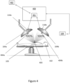
- the computer device 106 may comprise a processor 200 and a memory 202.
- a wall control panel 108 is shown in communication with the computer device 106; the function of the wall control panel 108 is described above.
- the wall control panel 108 is configured to display the GUI, which is further described below with reference to figures 10a and 10b .
- the light modules 104a, 104b comprise respective light module control panels 110a and 110b; again, the function of the light module control panels 110a, 110b is described below with reference to figures 9a, 9b and 9c .
- an indication system 300 comprises the computer device 306 which is in communication with each of the light modules 104a, 104b, and also in communication with a controller 308 which is in communication with the wall control panel 108. As can be seen, the controller 308 is also in communication with each of the light modules 104a, 104b. The controller 308 is configured to receive inputs from the wall control panel 108, or from the light module control panels 110a, 11 0b, and then issue corresponding commands to the light modules 104a, 104b to control their illumination outputs.
- controller 308 may be provided as a stand-alone device as shown in Figure 3 , or as part of one or more of the light modules 104a, 104b, as part of the indication system 300, or as part of the wall control panel 108.
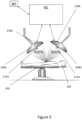
- an indication system 400 comprises computer device 401.
- the indication system 400 operates in a similar manner to indication systems 100 and 300 described above.
- indication system 400 is further connected to a detection system 402.
- the detection system 402 is configured to detect if illumination zones of the light modules 104a, 104b overlap. As shown in Figure 4 , the illumination zones may overlap in an overlapping region 403.
- the detection system 402 receives data from cameras 404a, 404b, in particular structured light cameras/systems, provided in each of the light modules 104a, 104b.
- Such a light module is marketed by Trumpf Medizin Systeme GmbH as iLED TM 7.
- the cameras 404a, 404b may be standard cameras, such as RGB cameras using a CCD or CMOS type sensor.
- the present disclosure also relates to a detection system 402 connected to, or comprising, a computer device 401, independent of the indication system 100 or 300.
- the detection system 401 may further comprise, as part of the computer device 401, an artificial neural network 600.
- the artificial neural network 600 may be trained using a training data set 700.
- the training data set 700 may comprise labelled data, wherein the labelled data includes pairs consisting of an input and a desired output.
- each node layer in the neural network 600 is configured to automatically learn to recognise features of the training data set 700 by repeatedly trying to reconstruct the input (i.e. the training data set).
- the neural network 600 learns by trying to minimize the difference between the network's outputs and the probability distribution of the training data set 700.
- the training data set 700 may be generated in conditions which are close to real conditions, i.e. conditions during use.
- the labelled data of the training data set 700 may comprise inputs such as images from cameras, e.g. structured light images from structured light systems, or RGB images from standard cameras. While this example relates to supervised machine learning to generate the neural network 600, the skilled person would understand that, where appropriate, semi-supervised machine learning, or other machine learning may be used.
- actual data 702 such as data from the structured light cameras 404a, 404b, is used as inputs, and the output may be whether there is an overlap 704 of the illumination zones of the light modules 104a, 104b.
- the output may further include a percentage of the overlap 704.
- the neural network 600 may be configured to recognise interference between structured light patterns of the structured light cameras 404a, 404b.
- the neural network 600 may be trained using data from the RGB cameras. If the actual data 702 is data from RGB cameras, the neural network 600 may be configured to recognise corresponding features, i.e. features present in the images of different RGB cameras. If the same features are detected in images of different RGB cameras, overlap may be recognised.
- the neural network 600 may be developed using an open source machine learning platform such as TensorFlow, or PyTorch.
- the neural network 600 is provided 800 with a training data set 702 to train the neural network 600 to recognise interference of structured light patterns.
- the trained neural network 600 is then provided 802 with actual data.
- the actual data may be pre-processed 803 to facilitate processing of the actual data by the neural network 600.
- the actual data may be pre-processed 803 by at least one of: cropping the input structured light images or RGB images; and reducing a resolution of the input structured light images or RGB images to increase the performance of overlap detection.
- Cropping the input may include cropping the input to correspond to the portion of the input corresponding to the corresponding illumination zone.
- the actual data 702, or the pre-processed actual data 702 if the actual data 702 is pre-processed in step 803, is processed by the neural network 600 to determine 804 if the structured light patterns of the structured light cameras 404a, 404b overlap.
- the structured light pattern produced by the structured light cameras may be configured to cover the entire illumination zone of the respective light module 104a, 104b so that any overlap in structured light pattern means that the illumination zones of the light modules 104a, 104b must also be overlapping.
- the information that the light patterns overlap is transmitted 806 to the computer device 401. If no interference is found, i.e. it is found that the structured light patterns do not overlap, the information that the light patterns do not overlap may be transmitted 806 to the computer device 401.
- the neural network 600 may be trained, and configured, to determine 810 a percentage overlap of the structured light patterns.
- the overlap percentage may be transmitted 812 to the computer device 401.
- the percentage overlap if the training and actual data is from RGB cameras, may also be determined using corresponding features from feature detection.
- the overlap percentage may be taken into account when determining if an indication is output. For example, the indication may only be output if the overlap percentage is greater than 10%, or greater than 20%, or greater than 30%.
- the predetermined period of time may be decreased, and the predetermined illumination setting amount may be decreased, upon the level of overlap increasing. That is to say, the predetermined period of time is shortest, and the predetermined illumination setting amount is lowest, upon the level of overlap being 100%; there being a direct relationship between the increase in the predetermined period of time, or the increase in the predetermined illumination setting amount, and the reduction in the level of overlap.
- the neural network 600 may be configured to continue training after the initial training with the training data set 700. For example, intermittently, the neural network 600 may request confirmation that the result of overlap detection (i.e. existence of overlap, percentage of overlap, or lack of overlap) is correct. Additionally or alternatively, the neural network 600 may be intermittently provided with additional training data, comprising pairs of inputs and desired outputs, to improve the neural network 600.
- the result of overlap detection i.e. existence of overlap, percentage of overlap, or lack of overlap
- additional training data comprising pairs of inputs and desired outputs, to improve the neural network 600.
- Figure 9a shows an example of the light module control panel 110a, 110b of the light modules 104a, 104b having an icon 900 which may be illuminated to output the indication.
- the icon 900 may be a button which may be pressed to acknowledge the indication.
- an illumination setting is changed using a light module control panel 110a, 11 0b, no acknowledgement of the indication should be required.
- the light module control panel 110a, 110b further comprises an input, in the form of a button 902, to switch the light module 104a, 104b between on and off, and inputs, in the form of buttons 904a, 904b, for increasing and decreasing the illumination setting of the light module 104a, 104b.
- Figures 9b and 9c show further examples of the light module control panel 110a, 110b, wherein instead of the indication icon 900 being illuminated, a light adjacent the icon may be illuminated to output the indication.
- the light module control panels 110a, 110b may further comprise an illumination setting indicator 906, which comprises a number of indicia to indicate a current illumination setting of the light module 104a, 104b.
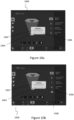
- FIGS. 10a and 10b show examples of Graphical User Interfaces (GUI) 1000 for outputting the indication.
- GUI Graphical User Interfaces
- the GUI may be displayed on the wall control panel 108 and/or on a third party device such as a tablet.
- the indication may be displayed within the GUI 1000 as a pop-up window 1002.
- the pop-up window 1002 may include one or more buttons for acknowledging the indication.
- the GUI comprises a "Cancel” button 1004 which may cause an automatic reduction in the illumination setting of at least one of the light modules 104a, 104b, or may simply cause removal of the indication, and an "OK" button 1006 which only acknowledges the indication, and may cause the requested increase in the illumination setting to be initiated.
- the pop-up window 1002 may provide a link, such as a hyperlink, to the relevant instructions for use (IFUs), and in particular the link may be to the particular page or section in the relevant instructions for use.
- a further pop-up window (not shown) may be provided with the relevant instructions for use for immediate review by the user.
- the system may provide access to the relevant instructions for use using the standard user interface for the instructions for use.
- Figure 10b of the example GUI 1000 shows an example of an additional indicator 1008, which may be displayed to draw further attention to the indication. Even after acknowledgement of the indication pop-up window 1002, the additional indicator 1008 may still be displayed in the GUI 1000.
- the indication may be displayed on more than one of the light module control panel 104a, 104b, a third party device, and the wall control panel 108.
Landscapes
- Engineering & Computer Science (AREA)
- Health & Medical Sciences (AREA)
- Life Sciences & Earth Sciences (AREA)
- Theoretical Computer Science (AREA)
- Physics & Mathematics (AREA)
- General Health & Medical Sciences (AREA)
- Surgery (AREA)
- Biomedical Technology (AREA)
- Molecular Biology (AREA)
- Software Systems (AREA)
- Medical Informatics (AREA)
- Evolutionary Computation (AREA)
- General Physics & Mathematics (AREA)
- Computing Systems (AREA)
- Artificial Intelligence (AREA)
- Pathology (AREA)
- Oral & Maxillofacial Surgery (AREA)
- Veterinary Medicine (AREA)
- Public Health (AREA)
- Animal Behavior & Ethology (AREA)
- Heart & Thoracic Surgery (AREA)
- Nuclear Medicine, Radiotherapy & Molecular Imaging (AREA)
- Multimedia (AREA)
- Data Mining & Analysis (AREA)
- Computational Linguistics (AREA)
- Biophysics (AREA)
- Mathematical Physics (AREA)
- General Engineering & Computer Science (AREA)
- Computer Vision & Pattern Recognition (AREA)
- Databases & Information Systems (AREA)
- Circuit Arrangement For Electric Light Sources In General (AREA)
- Endoscopes (AREA)
Priority Applications (1)
| Application Number | Priority Date | Filing Date | Title |
|---|---|---|---|
| EP24197061.5A EP4445862B1 (de) | 2021-03-31 | 2021-03-31 | Anzeigesystem für eine chirurgische beleuchtungsvorrichtung |
Applications Claiming Priority (2)
| Application Number | Priority Date | Filing Date | Title |
|---|---|---|---|
| EP21166456.0A EP4066775B1 (de) | 2021-03-31 | 2021-03-31 | Anzeigesystem für eine chirurgische beleuchtungsvorrichtung |
| EP24197061.5A EP4445862B1 (de) | 2021-03-31 | 2021-03-31 | Anzeigesystem für eine chirurgische beleuchtungsvorrichtung |
Related Parent Applications (2)
| Application Number | Title | Priority Date | Filing Date |
|---|---|---|---|
| EP21166456.0A Division-Into EP4066775B1 (de) | 2021-03-31 | 2021-03-31 | Anzeigesystem für eine chirurgische beleuchtungsvorrichtung |
| EP21166456.0A Division EP4066775B1 (de) | 2021-03-31 | 2021-03-31 | Anzeigesystem für eine chirurgische beleuchtungsvorrichtung |
Publications (3)
| Publication Number | Publication Date |
|---|---|
| EP4445862A2 true EP4445862A2 (de) | 2024-10-16 |
| EP4445862A3 EP4445862A3 (de) | 2024-10-23 |
| EP4445862B1 EP4445862B1 (de) | 2025-06-18 |
Family
ID=75339642
Family Applications (2)
| Application Number | Title | Priority Date | Filing Date |
|---|---|---|---|
| EP24197061.5A Active EP4445862B1 (de) | 2021-03-31 | 2021-03-31 | Anzeigesystem für eine chirurgische beleuchtungsvorrichtung |
| EP21166456.0A Active EP4066775B1 (de) | 2021-03-31 | 2021-03-31 | Anzeigesystem für eine chirurgische beleuchtungsvorrichtung |
Family Applications After (1)
| Application Number | Title | Priority Date | Filing Date |
|---|---|---|---|
| EP21166456.0A Active EP4066775B1 (de) | 2021-03-31 | 2021-03-31 | Anzeigesystem für eine chirurgische beleuchtungsvorrichtung |
Country Status (3)
| Country | Link |
|---|---|
| US (2) | US12315215B2 (de) |
| EP (2) | EP4445862B1 (de) |
| CN (1) | CN115802553A (de) |
Families Citing this family (3)
| Publication number | Priority date | Publication date | Assignee | Title |
|---|---|---|---|---|
| DE102018122428A1 (de) * | 2018-09-13 | 2020-03-19 | Osram Opto Semiconductors Gmbh | Verfahren zur steuerung einer beleuchtung eines objekts, system zur steuerung einer beleuchtung eines objekts und kamera |
| EP4568424A1 (de) * | 2023-12-06 | 2025-06-11 | Baxter Medical Systems GmbH + Co. KG | Verfahren zur bestimmung der intensität des sichtbaren lichts in einer beleuchtungszone eines chirurgischen lichtmoduls |
| CN119882571B (zh) * | 2025-03-25 | 2025-06-06 | 安徽生命港湾信息技术有限公司 | 一种用于楼宇的节能控制系统及方法 |
Family Cites Families (32)
| Publication number | Priority date | Publication date | Assignee | Title |
|---|---|---|---|---|
| US9955551B2 (en) * | 2002-07-12 | 2018-04-24 | Yechezkal Evan Spero | Detector controlled illuminating system |
| FR2849160B1 (fr) * | 2002-12-24 | 2005-03-18 | Alm | Dispositif d'eclairage et son utilisation |
| DE20315225U1 (de) | 2003-10-02 | 2005-02-10 | Karl Leibinger Medizintechnik Gmbh & Co. Kg | Medizinische Beleuchtungsvorrichtung mit Temperaturüberwachung des Arbeitsfeldes |
| EP1946618B9 (de) * | 2005-11-01 | 2013-12-25 | Koninklijke Philips N.V. | Verfahren, system und fernbedienung zum steuern der einstellungen jedes von mehreren spotlights |
| JP5145235B2 (ja) * | 2005-11-14 | 2013-02-13 | トルンプフ メディツィーン ジステーメ ゲゼルシャフト ミット ベシュレンクテル ハフツング ウント コンパニー コマンディートゲゼルシャフト | 手術用照明システム |
| ATE532000T1 (de) * | 2005-11-14 | 2011-11-15 | Trumpf Medizin Systeme Gmbh & Co Kg | Operationsleuchte |
| DE102008019191B4 (de) * | 2008-04-17 | 2017-10-05 | Drägerwerk AG & Co. KGaA | Vorrichtung und Verfahren zur gleichmäßigen Ausleuchtung eines Operationsfeldes |
| DE102008041284B4 (de) * | 2008-05-07 | 2010-05-27 | Carl Zeiss Surgical Gmbh | Ophthalmo-Operationsmikroskopsystem mit OCT-Messeinrichtung |
| PL2136128T3 (pl) | 2008-06-20 | 2011-06-30 | Trumpf Medizin Systeme Gmbh & Co Kg | Lampa operacyjna |
| DE102008034827A1 (de) * | 2008-07-22 | 2010-02-04 | Carl Zeiss Surgical Gmbh | Medizinisch-optisches Beobachtungssystem und Verfahren zum Schutz von Gewebe zu hoher Gewebebelastung durch Beleuchtungsstrahlung |
| DE102012014716A1 (de) * | 2012-07-25 | 2014-05-15 | Dräger Medical GmbH | Verfahren zur Verbesserung der Ausleuchtung eines Ausleuchtbereichs |
| WO2014067000A1 (en) | 2012-10-29 | 2014-05-08 | 7D Surgical Inc. | Integrated illumination and optical surface topology detection system and methods of use thereof |
| DE102013012231B4 (de) * | 2013-07-23 | 2022-07-14 | Drägerwerk AG & Co. KGaA | Verfahren für die Verbesserung der Ausleuchtung eines Ausleuchtbereichs einer Ausleuchtvorrichtung |
| DE102014222794A1 (de) * | 2014-11-07 | 2016-05-12 | Trumpf Medizin Systeme Gmbh + Co. Kg | Operationsleuchte und Verfahren zum Betreiben einer Operationsleuchte |
| US11153953B2 (en) | 2015-07-31 | 2021-10-19 | Stryker Corporation | Method and system for maximizing the output of surgical lights |
| DE102015113339A1 (de) * | 2015-08-13 | 2017-02-16 | Karl Leibinger Medizintechnik Gmbh & Co. Kg | Operationsleuchte mit Helligkeitsregulierung |
| US11754267B2 (en) * | 2015-12-10 | 2023-09-12 | 7D Surgical Inc. | Optical alignment system |
| US9638406B1 (en) * | 2016-03-02 | 2017-05-02 | Amtai Medical Equipment, Inc. | Energy-saving device of surgical light |
| WO2017207321A1 (en) * | 2016-05-30 | 2017-12-07 | Philips Lighting Holding B.V. | Illumination control |
| US10767822B2 (en) | 2016-06-24 | 2020-09-08 | Brian Munari | Automatic light control for illumination of a feature of interest |
| US10271398B2 (en) * | 2016-11-01 | 2019-04-23 | American Sterilizer Company | Adaptive shadow control system for a surgical lighting system |
| EP3547976B1 (de) | 2016-11-30 | 2021-07-07 | Alcon Inc. | System zur überwachung der phototoxizität während der augenchirurgie |
| JP2018199800A (ja) * | 2017-05-30 | 2018-12-20 | ヘンケルジャパン株式会社 | 湿気硬化型ホットメルト接着剤 |
| US10788200B2 (en) * | 2017-05-30 | 2020-09-29 | Simon Anthony Abou-Fadel | Lighting system and method for operating lighting system |
| WO2019043631A1 (en) | 2017-08-31 | 2019-03-07 | Gentex Corporation | LIGHTING SYSTEMS |
| DE102017011624A1 (de) * | 2017-12-15 | 2019-06-19 | Drägerwerk AG & Co. KGaA | Beleuchtungsvorrichtung, Operationsleuchte, Verfahren und Computerprogramm zur Steuerung einer Vielzahl von Leuchtelementen in einer Beleuchtungsvorrichtung |
| CN112020321A (zh) * | 2018-03-29 | 2020-12-01 | 270医疗器械公司 | 医学成像系统和用于检测其位置的方法 |
| JPWO2019187762A1 (ja) * | 2018-03-30 | 2021-06-17 | ソニーグループ株式会社 | 手術用観察装置、および制御方法 |
| EP3556318B1 (de) | 2018-04-20 | 2021-09-01 | TRUMPF Medizin Systeme GmbH + Co. KG | Operationsleuchte |
| JPWO2019225231A1 (ja) * | 2018-05-22 | 2021-07-15 | ソニーグループ株式会社 | 手術用情報処理装置、情報処理方法及びプログラム |
| EP3875844A4 (de) * | 2018-11-02 | 2021-11-24 | Nanjing Mindray Bio-Medical Electronics Co., Ltd. | Operationssaalbeleuchtungssystem, steuerungsverfahren und -vorrichtung dafür sowie speichermedium |
| EP3889493A1 (de) * | 2020-03-30 | 2021-10-06 | TRUMPF Medizin Systeme GmbH + Co. KG | Chirurgisches lichtsystem und verfahren zum betreiben eines chirurgischen lichtsystems |
-
2021
- 2021-03-31 EP EP24197061.5A patent/EP4445862B1/de active Active
- 2021-03-31 EP EP21166456.0A patent/EP4066775B1/de active Active
-
2022
- 2022-03-28 US US17/705,541 patent/US12315215B2/en active Active
- 2022-03-29 CN CN202210326271.0A patent/CN115802553A/zh active Pending
-
2025
- 2025-04-29 US US19/192,779 patent/US20250259414A1/en active Pending
Also Published As
| Publication number | Publication date |
|---|---|
| EP4066775B1 (de) | 2025-12-10 |
| EP4445862A3 (de) | 2024-10-23 |
| US20250259414A1 (en) | 2025-08-14 |
| EP4066775A1 (de) | 2022-10-05 |
| CN115802553A (zh) | 2023-03-14 |
| US20220327801A1 (en) | 2022-10-13 |
| EP4445862B1 (de) | 2025-06-18 |
| US12315215B2 (en) | 2025-05-27 |
Similar Documents
| Publication | Publication Date | Title |
|---|---|---|
| US20250259414A1 (en) | Indication system for a surgical lighting apparatus | |
| US20130310652A1 (en) | Integrated surgical task lighting | |
| CN1198244C (zh) | 控制方法 | |
| US10922630B2 (en) | Queuing apparatus, and queuing control method thereof | |
| JP5288606B2 (ja) | 照明システム | |
| AU2003284816A1 (en) | Method and installation for detecting and following an eye and the gaze direction thereof | |
| CN101976109A (zh) | 一种智能显示器及其显示控制装置和方法 | |
| JP2017098180A (ja) | 照明装置 | |
| CN110658742A (zh) | 多模态协同操控的轮椅控制系统及方法 | |
| CN104470128A (zh) | 一种亮度调节方法及电子设备 | |
| CN104254184A (zh) | 能追踪并适应人眼睛的灯光控制装置 | |
| JP2004303251A (ja) | 制御方法 | |
| WO2020148697A3 (en) | Method and system for monitoring a person using infrared and visible light | |
| JP2010123373A (ja) | 照明システム | |
| CN105554981B (zh) | 台灯调节方法和装置 | |
| CN113692098A (zh) | 一种教室照明光环境模拟方法 | |
| JP2016018644A (ja) | 照明制御システム | |
| CN109547916B (zh) | 智能照明设备、通信系统及室内定位方法 | |
| JP2008235114A (ja) | 照明制御方法および照明制御システム | |
| US20250189367A1 (en) | Method for determining visible light intensity at an illumination zone of a surgical light module | |
| US11195525B2 (en) | Operation terminal, voice inputting method, and computer-readable recording medium | |
| WO2015170720A1 (ja) | 画像認識装置および画像認識方法 | |
| CN117440571A (zh) | 亮度调节方法、电子设备、机器人、存储介质及程序产品 | |
| JP2010161783A (ja) | 情報処理装置 | |
| JP2005284408A (ja) | キッチン作業支援システム |
Legal Events
| Date | Code | Title | Description |
|---|---|---|---|
| PUAI | Public reference made under article 153(3) epc to a published international application that has entered the european phase |
Free format text: ORIGINAL CODE: 0009012 |
|
| STAA | Information on the status of an ep patent application or granted ep patent |
Free format text: STATUS: THE APPLICATION HAS BEEN PUBLISHED |
|
| PUAL | Search report despatched |
Free format text: ORIGINAL CODE: 0009013 |
|
| STAA | Information on the status of an ep patent application or granted ep patent |
Free format text: STATUS: REQUEST FOR EXAMINATION WAS MADE |
|
| AC | Divisional application: reference to earlier application |
Ref document number: 4066775 Country of ref document: EP Kind code of ref document: P |
|
| AK | Designated contracting states |
Kind code of ref document: A2 Designated state(s): AL AT BE BG CH CY CZ DE DK EE ES FI FR GB GR HR HU IE IS IT LI LT LU LV MC MK MT NL NO PL PT RO RS SE SI SK SM TR |
|
| AK | Designated contracting states |
Kind code of ref document: A3 Designated state(s): AL AT BE BG CH CY CZ DE DK EE ES FI FR GB GR HR HU IE IS IT LI LT LU LV MC MK MT NL NO PL PT RO RS SE SI SK SM TR |
|
| RIC1 | Information provided on ipc code assigned before grant |
Ipc: A61B 90/30 20160101AFI20240917BHEP |
|
| 17P | Request for examination filed |
Effective date: 20241007 |
|
| RBV | Designated contracting states (corrected) |
Designated state(s): AL AT BE BG CH CY CZ DE DK EE ES FI FR GB GR HR HU IE IS IT LI LT LU LV MC MK MT NL NO PL PT RO RS SE SI SK SM TR |
|
| GRAP | Despatch of communication of intention to grant a patent |
Free format text: ORIGINAL CODE: EPIDOSNIGR1 |
|
| STAA | Information on the status of an ep patent application or granted ep patent |
Free format text: STATUS: GRANT OF PATENT IS INTENDED |
|
| INTG | Intention to grant announced |
Effective date: 20250117 |
|
| RIC1 | Information provided on ipc code assigned before grant |
Ipc: G06N 3/08 20230101ALN20250113BHEP Ipc: A61B 34/20 20160101ALN20250113BHEP Ipc: A61B 90/00 20160101ALI20250113BHEP Ipc: A61B 90/30 20160101AFI20250113BHEP |
|
| GRAS | Grant fee paid |
Free format text: ORIGINAL CODE: EPIDOSNIGR3 |
|
| GRAA | (expected) grant |
Free format text: ORIGINAL CODE: 0009210 |
|
| STAA | Information on the status of an ep patent application or granted ep patent |
Free format text: STATUS: THE PATENT HAS BEEN GRANTED |
|
| AC | Divisional application: reference to earlier application |
Ref document number: 4066775 Country of ref document: EP Kind code of ref document: P |
|
| AK | Designated contracting states |
Kind code of ref document: B1 Designated state(s): AL AT BE BG CH CY CZ DE DK EE ES FI FR GB GR HR HU IE IS IT LI LT LU LV MC MK MT NL NO PL PT RO RS SE SI SK SM TR |
|
| REG | Reference to a national code |
Ref country code: GB Ref legal event code: FG4D |
|
| REG | Reference to a national code |
Ref country code: CH Ref legal event code: EP |
|
| REG | Reference to a national code |
Ref country code: DE Ref legal event code: R096 Ref document number: 602021032657 Country of ref document: DE |
|
| REG | Reference to a national code |
Ref country code: CH Ref legal event code: EP |
|
| REG | Reference to a national code |
Ref country code: IE Ref legal event code: FG4D |
|
| PG25 | Lapsed in a contracting state [announced via postgrant information from national office to epo] |
Ref country code: FI Free format text: LAPSE BECAUSE OF FAILURE TO SUBMIT A TRANSLATION OF THE DESCRIPTION OR TO PAY THE FEE WITHIN THE PRESCRIBED TIME-LIMIT Effective date: 20250618 |
|
| REG | Reference to a national code |
Ref country code: LT Ref legal event code: MG9D |
|
| PG25 | Lapsed in a contracting state [announced via postgrant information from national office to epo] |
Ref country code: GR Free format text: LAPSE BECAUSE OF FAILURE TO SUBMIT A TRANSLATION OF THE DESCRIPTION OR TO PAY THE FEE WITHIN THE PRESCRIBED TIME-LIMIT Effective date: 20250919 Ref country code: NO Free format text: LAPSE BECAUSE OF FAILURE TO SUBMIT A TRANSLATION OF THE DESCRIPTION OR TO PAY THE FEE WITHIN THE PRESCRIBED TIME-LIMIT Effective date: 20250918 |
|
| PG25 | Lapsed in a contracting state [announced via postgrant information from national office to epo] |
Ref country code: BG Free format text: LAPSE BECAUSE OF FAILURE TO SUBMIT A TRANSLATION OF THE DESCRIPTION OR TO PAY THE FEE WITHIN THE PRESCRIBED TIME-LIMIT Effective date: 20250618 |
|
| PG25 | Lapsed in a contracting state [announced via postgrant information from national office to epo] |
Ref country code: HR Free format text: LAPSE BECAUSE OF FAILURE TO SUBMIT A TRANSLATION OF THE DESCRIPTION OR TO PAY THE FEE WITHIN THE PRESCRIBED TIME-LIMIT Effective date: 20250618 |
|
| PG25 | Lapsed in a contracting state [announced via postgrant information from national office to epo] |
Ref country code: RS Free format text: LAPSE BECAUSE OF FAILURE TO SUBMIT A TRANSLATION OF THE DESCRIPTION OR TO PAY THE FEE WITHIN THE PRESCRIBED TIME-LIMIT Effective date: 20250918 |
|
| REG | Reference to a national code |
Ref country code: NL Ref legal event code: MP Effective date: 20250618 |
|
| PG25 | Lapsed in a contracting state [announced via postgrant information from national office to epo] |
Ref country code: LV Free format text: LAPSE BECAUSE OF FAILURE TO SUBMIT A TRANSLATION OF THE DESCRIPTION OR TO PAY THE FEE WITHIN THE PRESCRIBED TIME-LIMIT Effective date: 20250618 |
|
| PG25 | Lapsed in a contracting state [announced via postgrant information from national office to epo] |
Ref country code: NL Free format text: LAPSE BECAUSE OF FAILURE TO SUBMIT A TRANSLATION OF THE DESCRIPTION OR TO PAY THE FEE WITHIN THE PRESCRIBED TIME-LIMIT Effective date: 20250618 |