EP4445837A2 - Vorrichtung zur automatisierten bestimmung einer lumenkontur eines blutgefässes - Google Patents
Vorrichtung zur automatisierten bestimmung einer lumenkontur eines blutgefässes Download PDFInfo
- Publication number
- EP4445837A2 EP4445837A2 EP24196775.1A EP24196775A EP4445837A2 EP 4445837 A2 EP4445837 A2 EP 4445837A2 EP 24196775 A EP24196775 A EP 24196775A EP 4445837 A2 EP4445837 A2 EP 4445837A2
- Authority
- EP
- European Patent Office
- Prior art keywords
- vessel
- diameter
- user interface
- graphical user
- lumen
- Prior art date
- Legal status (The legal status is an assumption and is not a legal conclusion. Google has not performed a legal analysis and makes no representation as to the accuracy of the status listed.)
- Pending
Links
Images


Classifications
-
- G—PHYSICS
- G16—INFORMATION AND COMMUNICATION TECHNOLOGY [ICT] SPECIALLY ADAPTED FOR SPECIFIC APPLICATION FIELDS
- G16H—HEALTHCARE INFORMATICS, i.e. INFORMATION AND COMMUNICATION TECHNOLOGY [ICT] SPECIALLY ADAPTED FOR THE HANDLING OR PROCESSING OF MEDICAL OR HEALTHCARE DATA
- G16H30/00—ICT specially adapted for the handling or processing of medical images
- G16H30/20—ICT specially adapted for the handling or processing of medical images for handling medical images, e.g. DICOM, HL7 or PACS
-
- A—HUMAN NECESSITIES
- A61—MEDICAL OR VETERINARY SCIENCE; HYGIENE
- A61B—DIAGNOSIS; SURGERY; IDENTIFICATION
- A61B5/00—Measuring for diagnostic purposes; Identification of persons
- A61B5/0059—Measuring for diagnostic purposes; Identification of persons using light, e.g. diagnosis by transillumination, diascopy, fluorescence
- A61B5/0062—Arrangements for scanning
- A61B5/0066—Optical coherence imaging
-
- A—HUMAN NECESSITIES
- A61—MEDICAL OR VETERINARY SCIENCE; HYGIENE
- A61B—DIAGNOSIS; SURGERY; IDENTIFICATION
- A61B5/00—Measuring for diagnostic purposes; Identification of persons
- A61B5/02—Detecting, measuring or recording for evaluating the cardiovascular system, e.g. pulse, heart rate, blood pressure or blood flow
- A61B5/02007—Evaluating blood vessel condition, e.g. elasticity, compliance
-
- A—HUMAN NECESSITIES
- A61—MEDICAL OR VETERINARY SCIENCE; HYGIENE
- A61B—DIAGNOSIS; SURGERY; IDENTIFICATION
- A61B5/00—Measuring for diagnostic purposes; Identification of persons
- A61B5/103—Measuring devices for testing the shape, pattern, colour, size or movement of the body or parts thereof, for diagnostic purposes
- A61B5/107—Measuring physical dimensions, e.g. size of the entire body or parts thereof
- A61B5/1076—Measuring physical dimensions, e.g. size of the entire body or parts thereof for measuring dimensions inside body cavities, e.g. using catheters
-
- A—HUMAN NECESSITIES
- A61—MEDICAL OR VETERINARY SCIENCE; HYGIENE
- A61B—DIAGNOSIS; SURGERY; IDENTIFICATION
- A61B5/00—Measuring for diagnostic purposes; Identification of persons
- A61B5/74—Details of notification to user or communication with user or patient; User input means
- A61B5/742—Details of notification to user or communication with user or patient; User input means using visual displays
- A61B5/743—Displaying an image simultaneously with additional graphical information, e.g. symbols, charts, function plots
-
- A—HUMAN NECESSITIES
- A61—MEDICAL OR VETERINARY SCIENCE; HYGIENE
- A61B—DIAGNOSIS; SURGERY; IDENTIFICATION
- A61B5/00—Measuring for diagnostic purposes; Identification of persons
- A61B5/74—Details of notification to user or communication with user or patient; User input means
- A61B5/7475—User input or interface means, e.g. keyboard, pointing device, joystick
- A61B5/748—Selection of a region of interest, e.g. using a graphics tablet
-
- A—HUMAN NECESSITIES
- A61—MEDICAL OR VETERINARY SCIENCE; HYGIENE
- A61F—FILTERS IMPLANTABLE INTO BLOOD VESSELS; PROSTHESES; DEVICES PROVIDING PATENCY TO, OR PREVENTING COLLAPSING OF, TUBULAR STRUCTURES OF THE BODY, e.g. STENTS; ORTHOPAEDIC, NURSING OR CONTRACEPTIVE DEVICES; FOMENTATION; TREATMENT OR PROTECTION OF EYES OR EARS; BANDAGES, DRESSINGS OR ABSORBENT PADS; FIRST-AID KITS
- A61F2/00—Filters implantable into blood vessels; Prostheses, i.e. artificial substitutes or replacements for parts of the body; Appliances for connecting them with the body; Devices providing patency to, or preventing collapsing of, tubular structures of the body, e.g. stents
- A61F2/82—Devices providing patency to, or preventing collapsing of, tubular structures of the body, e.g. stents
- A61F2/86—Stents in a form characterised by the wire-like elements; Stents in the form characterised by a net-like or mesh-like structure
-
- G—PHYSICS
- G16—INFORMATION AND COMMUNICATION TECHNOLOGY [ICT] SPECIALLY ADAPTED FOR SPECIFIC APPLICATION FIELDS
- G16H—HEALTHCARE INFORMATICS, i.e. INFORMATION AND COMMUNICATION TECHNOLOGY [ICT] SPECIALLY ADAPTED FOR THE HANDLING OR PROCESSING OF MEDICAL OR HEALTHCARE DATA
- G16H20/00—ICT specially adapted for therapies or health-improving plans, e.g. for handling prescriptions, for steering therapy or for monitoring patient compliance
- G16H20/40—ICT specially adapted for therapies or health-improving plans, e.g. for handling prescriptions, for steering therapy or for monitoring patient compliance relating to mechanical, radiation or invasive therapies, e.g. surgery, laser therapy, dialysis or acupuncture
-
- G—PHYSICS
- G16—INFORMATION AND COMMUNICATION TECHNOLOGY [ICT] SPECIALLY ADAPTED FOR SPECIFIC APPLICATION FIELDS
- G16H—HEALTHCARE INFORMATICS, i.e. INFORMATION AND COMMUNICATION TECHNOLOGY [ICT] SPECIALLY ADAPTED FOR THE HANDLING OR PROCESSING OF MEDICAL OR HEALTHCARE DATA
- G16H50/00—ICT specially adapted for medical diagnosis, medical simulation or medical data mining; ICT specially adapted for detecting, monitoring or modelling epidemics or pandemics
- G16H50/20—ICT specially adapted for medical diagnosis, medical simulation or medical data mining; ICT specially adapted for detecting, monitoring or modelling epidemics or pandemics for computer-aided diagnosis, e.g. based on medical expert systems
-
- A—HUMAN NECESSITIES
- A61—MEDICAL OR VETERINARY SCIENCE; HYGIENE
- A61B—DIAGNOSIS; SURGERY; IDENTIFICATION
- A61B90/00—Instruments, implements or accessories specially adapted for surgery or diagnosis and not covered by any of the groups A61B1/00 - A61B50/00, e.g. for luxation treatment or for protecting wound edges
- A61B90/06—Measuring instruments not otherwise provided for
- A61B2090/061—Measuring instruments not otherwise provided for for measuring dimensions, e.g. length
-
- A—HUMAN NECESSITIES
- A61—MEDICAL OR VETERINARY SCIENCE; HYGIENE
- A61F—FILTERS IMPLANTABLE INTO BLOOD VESSELS; PROSTHESES; DEVICES PROVIDING PATENCY TO, OR PREVENTING COLLAPSING OF, TUBULAR STRUCTURES OF THE BODY, e.g. STENTS; ORTHOPAEDIC, NURSING OR CONTRACEPTIVE DEVICES; FOMENTATION; TREATMENT OR PROTECTION OF EYES OR EARS; BANDAGES, DRESSINGS OR ABSORBENT PADS; FIRST-AID KITS
- A61F2/00—Filters implantable into blood vessels; Prostheses, i.e. artificial substitutes or replacements for parts of the body; Appliances for connecting them with the body; Devices providing patency to, or preventing collapsing of, tubular structures of the body, e.g. stents
- A61F2/82—Devices providing patency to, or preventing collapsing of, tubular structures of the body, e.g. stents
-
- A—HUMAN NECESSITIES
- A61—MEDICAL OR VETERINARY SCIENCE; HYGIENE
- A61F—FILTERS IMPLANTABLE INTO BLOOD VESSELS; PROSTHESES; DEVICES PROVIDING PATENCY TO, OR PREVENTING COLLAPSING OF, TUBULAR STRUCTURES OF THE BODY, e.g. STENTS; ORTHOPAEDIC, NURSING OR CONTRACEPTIVE DEVICES; FOMENTATION; TREATMENT OR PROTECTION OF EYES OR EARS; BANDAGES, DRESSINGS OR ABSORBENT PADS; FIRST-AID KITS
- A61F2230/00—Geometry of prostheses classified in groups A61F2/00 - A61F2/26 or A61F2/82 or A61F9/00 or A61F11/00 or subgroups thereof
- A61F2230/0063—Three-dimensional shapes
- A61F2230/0069—Three-dimensional shapes cylindrical
-
- A—HUMAN NECESSITIES
- A61—MEDICAL OR VETERINARY SCIENCE; HYGIENE
- A61F—FILTERS IMPLANTABLE INTO BLOOD VESSELS; PROSTHESES; DEVICES PROVIDING PATENCY TO, OR PREVENTING COLLAPSING OF, TUBULAR STRUCTURES OF THE BODY, e.g. STENTS; ORTHOPAEDIC, NURSING OR CONTRACEPTIVE DEVICES; FOMENTATION; TREATMENT OR PROTECTION OF EYES OR EARS; BANDAGES, DRESSINGS OR ABSORBENT PADS; FIRST-AID KITS
- A61F2240/00—Manufacturing or designing of prostheses classified in groups A61F2/00 - A61F2/26 or A61F2/82 or A61F9/00 or A61F11/00 or subgroups thereof
- A61F2240/001—Designing or manufacturing processes
-
- A—HUMAN NECESSITIES
- A61—MEDICAL OR VETERINARY SCIENCE; HYGIENE
- A61F—FILTERS IMPLANTABLE INTO BLOOD VESSELS; PROSTHESES; DEVICES PROVIDING PATENCY TO, OR PREVENTING COLLAPSING OF, TUBULAR STRUCTURES OF THE BODY, e.g. STENTS; ORTHOPAEDIC, NURSING OR CONTRACEPTIVE DEVICES; FOMENTATION; TREATMENT OR PROTECTION OF EYES OR EARS; BANDAGES, DRESSINGS OR ABSORBENT PADS; FIRST-AID KITS
- A61F2250/00—Special features of prostheses classified in groups A61F2/00 - A61F2/26 or A61F2/82 or A61F9/00 or A61F11/00 or subgroups thereof
- A61F2250/0058—Additional features; Implant or prostheses properties not otherwise provided for
- A61F2250/006—Additional features; Implant or prostheses properties not otherwise provided for modular
Definitions
- OCT and IVUS imaging modalities guide stent deployment in only a small fraction of interventional procedures.
- OCT and IVUS imaging modalities guide stent deployment in only a small fraction of interventional procedures.
- One reason for the limited use of OCT and IVUS imaging for stent deployment is that the current procedures for determining the optimal diameter and length of the stent are subjective and time-consuming.
- the present invention addresses this need and others.
- the invention relates to a method for sizing and adjusting a stent for restoration of the contour of a narrowed vessel.
- the method includes the steps of: dividing the vessel into a plurality of segments, each segment being defined as the space between branches of the vessel; selecting a starting point that appears to have substantially no plaque; defining the diameter at this point to be the maximum diameter; calculating the maximal diameter of the next adjacent segment according to a power law; measuring the actual diameter of the next adjacent segment; selecting either the calculated maximum diameter or the measured maximum diameter depending upon which diameter is larger; using the selected maximum diameter to find the maximum diameter of this next segment; iteratively proceeding until every segment of the vessel in which the stent is to be placed is examined; and selecting a stent in response to the diameters of the end proximal and distal segments.
- the maximum diameter of a segment is determined in response to its measured diameter, its calculated mean diameter and its quality.
- ⁇ has a value between about 2.0 and about 3.0.
- the normality of the tissue is determined by a method selected from the group of automated tissue characterization, user identification and morphology.
- the method of automated tissue characterization utilizes cross-correlation of the OCT signal between adjacent regions of the vessel.
- the method of automated tissue characterization utilizes IM to OA ratios.
- frames of interest are first filtered with a Gabor filter.
- the method of automated tissue characterization utilizes frame based intensity profiles.
- the method further comprises determining where in the vessel the stent should make contact by determining the amount of disease present in the vessel.
- the invention in another aspect, relates to an apparatus for sizing a stent for placement in a vessel.
- the apparatus includes a processor having imaging data for the vessel, the processor executing program having the steps: dividing the vessel into a plurality of segments, each segment being defined as the space between branches of the vessel; selecting a starting point that appears to have substantially no plaque; defining the diameter at this point to be the maximum diameter; calculating the maximal diameter of the next adjacent segment according to a power law; measuring the actual diameter of the next adjacent segment; selecting either the calculated maximum diameter or the measured maximum diameter depending upon which diameter is larger; using the selected maximum diameter to find the maximum diameter of this next segment; and iteratively proceeding until every segment of the vessel in which the stent is to be placed is examined; and displaying the results to allow a user to select a stent in response to the diameters of the end proximal and distal segments.
- automated tissue characterization utilizes cross-correlation of the OCT signal between adjacent regions of the vessel.
- automated tissue characterization utilizes IM to OA ratios.
- the processor first filters image data of the vessel segments using a Gabor filter.
- the processor performs automated tissue characterization utilizing frame-based intensity profiles.
- the processor determines where in the vessel the stent should make contact by determining the amount of disease present in the vessel.
- the invention in another aspect, relates to a processor-based method of displaying a representation of a section of a blood vessel.
- the method includes generating a set of data in response to distance measurements of the section of the blood vessel using an optical coherence tomography system, the set comprising a plurality of cross-sectional areas at a plurality of positions along the section; displaying a first panel having a first axis and a second axis, the first panel comprising a first longitudinal image view of the section of the blood vessel, wherein the first axis corresponds to a diameter value, wherein the second axis corresponds to a position along the section of the blood vessel; and displaying a minimum lumen area for the section of the blood vessel.
- the diameter value is displayed as a mean diameter or a measured diameter.
- the step of generating the first longitudinal view uses a plurality of mean cross-sectional diameters.
- the method includes displaying, in a second panel, a longitudinal view of the of the section of the blood vessel, wherein the first axis corresponds to a diameter value, wherein the second axis corresponds to a position along the section of the blood vessel and a branch of the blood vessel as a perpendicular bar.
- the width of the bar is sized such that it equals the width of the branch.
- OCT optical coherence tomography
- IVUS intravascular ultrasound
- other intravascular imaging modalities provide valuable information about vessel dimensions and plaque characteristics.
- current imaging systems do not present this information in a way that is easy to interpret for proper stent selection and deployment.
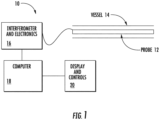
- Fig. 1 is a block diagram of an embodiment of an OCT system 10 constructed in accordance to the present invention.
- the system 10 includes an optical probe 12 sized for insertion into the blood vessel of interest 14. Light is passed into the probe 12 and light reflections from the tissue received from the probe 12 and passed to an interferometric and electronics module 16. The electronic signals corresponding to light received from the probe 12 are passed to a processor module 14 and manipulated as described herein. The results are displayed on a graphics display and control unit 20.
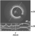
- Figs. 2a and 2b show an embodiment of a commercially available OCT system display that depicts images obtained from a coronary artery.
- a single transverse cross-sectional image of a blood vessel is displayed at a user-selected longitudinal position ( Fig. 2a ), along with a single longitudinal cross section (shown as a vertical line (a-a') through the longitudinal image of Fig. 1b) at a user-selected angle and location within the vessel.
- a-a' a vertical line
- the cross section at that location appears in Fig. 2a .
- a cardiologist typically employs a multi-step process to extract the information needed to choose the appropriate size and length of a stent for treating a lesion such as a stenosis caused by plaque.
- the steps generally required are: looking through the image set to find narrowest lumen cross section; measuring the minimum lumen area
- MLA plaque burden and largest lumen diameter
- the cardiologist then readjusts the positions of the reference cross sections to account for the presence of nearby branches. Once this is complete, the cardiologist then must measure the distance L in mm between the proximal and distal reference cross sections and choose a stent with a length greater than the segment length L and with a diameter between D d and D p that will, after expansion, ensure good strut apposition without overextending the arterial wall. If necessary, the cardiologist then must plan for post-dilation with a balloon catheter to taper the stent diameter to achieve better conformance with the normal taper of the vessel lumen.
- OCT and IVUS imaging are also valuable for assessing the quality of stent expansion after implantation.
- vessel cross sections located proximal and distal to the implanted stent are used as references to judge whether the stent has been expanded properly.
- these reference cross sections are usually found by using a subjective manual procedure similar to the one outlined above. As a result, similar difficulties with lumen tapering and side branches are often encountered, which hinder quantification of target diameters for balloon dilation as presently used.
- Fig. 3 is an embodiment of a simplified version of a display of the mean-diameter of the lumen known to the prior art.
- the solid black regions show variations in the mean diameter of the lumen of the vessel segment, as well as the longitudinal positions and diameters of the side branches within the segment.
- the horizontal axis represents the image frame number, which corresponds to the distance along the axis of the vessel.
- the image frame at which the lumen area is a minimum serves as a marker for measurement of the percent area stenosis relative to the cross-sectional area measured at one or more reference frames.
- the reference diameters are intended to represent the diameters of the lumen in segments of the vessel that are acceptable points of contact between the vessel and the edges of the stent.
- the best points of contact are those regions of the artery where lumen area is a local maximum and where plaque is minimal (i.e., the intima is thin and uniform).
- the mean diameter profile display does not provide a reliable indication of the natural tapering of the vessel. That is, the diameters of blood vessels typically taper as one proceeds along the vessel away from the heart. To locate suitable normal reference cross sections, the user must still search manually through the set of image frames within the regions where the diameter is largest to choose the best candidates. Once suitable reference frames have been located, a rough measure of the amount of tapering in the vessel can be obtained from the difference between the mean diameters measured at a pair of reference frames located proximally and distally to the MLA frame respectively.
- the intent of the invention disclosed herein is to simplify stent planning, evaluation and adjustment by automating the procedures for determining the optimum lumen contour of a stented vessel.
- This optimum contour is intended to serve as an objective guide for stent sizing, deployment, and post-stent evaluation. Determination of the optimum lumen contour is based on quantitative image-processing methods that account for plaque thickness, size and location of side branches, and vessel tapering.
- Various embodiments of the invention extend the utility of OCT- or IVUS-derived mean diameter data by eliminating manual operations involved in the selection of the normal reference cross sections and the estimation of the tapered normal vessel profile for stent sizing.
- each segment is defined as the space between the branches of the vessel.
- each branch of the vessel is shown as a vertical line extending downward from the vessel regardless of the actual orientation of the branch around the circumference of the vessel.
- Branch locations and diameters are determined by software algorithms that automatically locate and measure discontinuities in the circumference of the lumen contour of vessel cross sections.
- the method then uses a starting point, for example, the most distal segment (1) of the vessel in the general area in which the stent is intended to be placed that appears to be substantially unstenosed.
- the current maximum diameter D max (1) is assumed to be defined at this location.
- the method then evaluates the next segment (2), in this case the adjacent proximal segment, and calculates what the maximal diameter of the next proximal segment (2) should be, given the diameter of the present segment, the diameter of the branch between the segments and knowledge that the vessel tapers according to a power rule as described below.
- the actual diameter of the next proximal segment is measured and whichever diameter (measured or calculated) is larger is used as the maximum diameter of this next segment D max (2).
- the process then proceeds to the next proximal segment and so on until the entire length of the vessel in which the stent is to be placed is examined. At this point, the expanded diameters of both ends of the stent are defined.
- Another embodiment is similar to the previously discussed embodiment except that the quality (degree of severity of disease) of the maximum diameter is determined. If the segment having the maximum diameter within a segment appears to be diseased, other image frames within that segment are examined and the less diseased frame is chosen for the maximum diameter. In this way, the maximum diameter frame used may actually have a smaller physical diameter but may also have a smaller diseased portion of the lumen, and so is more likely to be indicative of the actual lumen diameter.
- D ⁇ i + 1 D ⁇ i + D b ⁇ i
- D(i) and D ( i +1) are the lumen diameters in the vessel segments distal and proximal, respectively, to the ith branch.
- the ith side branch has a diameter D b ( i ).
- the exponent ⁇ is a power-law scaling exponent which has a value between about 2 and about 3.0 as determined empirically. Selection of the best value of ⁇ is based on statistical analysis of OCT and angiographic image databases in which the tapering of the vessels and the branch diameters of those vessels are measured. In normal patients, the value is typically about 2.5
- the image of the vessel is divided into N+1 inter-branch segments, where N is the number of side branches.
- N is the number of side branches.
- the mean diameter of each inter-branch segment is then determined by examining the frames that make up the segment.
- the image frame in each segment in which the lumen diameter equals the maximum for that segment becomes a candidate for the normal reference segment, that is, the largest diameter in the vessel without stenosis.
- Boundary tracing methods such as described in US Patent Publication No. 2011/0071404 , when applied to the raw intravascular image data, can be used to measure the mean lumen and branch diameters automatically.
- one embodiment of the boundary tracing method to detect the lumen of a vessel first includes making an image mask to demark the general contour of the lumen wall.
- the mask is binary.
- the mask is made of a plurality of scanlines, with each scanline defining the beginning and end of a tissue area. Because it is possible that a scanline may include more than one region of tissue, due to blood artifacts etc., a weight is associated with each region of tissue.
- a list of weighted tissue is created and potential contours defined.
- the longest contour segment is defined as the root contour segment.
- the next adjacent contour segments, both clockwise and counter-clockwise, are then identified.
- a valid next contour segment is one that passes both angular, radial and Euclidian distance and length thresholds. That is, its angular extent must be greater than a certain threshold; its radial position must be similar to the other segments; and its direct connection distance (Euclidian distance) to the next adjacent contour segment must be greater than a certain threshold.
- the lengths of the potential contour segments are determined and the one with the longest length selected as an actual contour segment. Missing contour data between contour segments is then interpolated to remove the gaps in the contour. At this point, a full contour of the lumen has been defined in each frame of a given vessel segment.
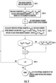
- One specific embodiment of the invention applies to the first situation when no information about the characteristics of the plaque in the wall is available for determining the degree of normality of particular vessel segments. This case may arise when the imaging modality is unable to distinguish diseased and normal tissue or when imaging quality has been degraded.
- the flowchart shows one embodiment of the computations and decisions used to determine the optimum stented profile of the vessel when no information about normal vessel diameters is available.
- One feature of the method shown is that the method is designed to prevent overexpansion of the stent while still incorporating information from all inter-branch segments.
- the mean diameter of each segment and side branch is measured. (Step 1).
- the mean diameter is the diameter of a circle which has the same area as that of the cross section of the vessel at that location in the segment.
- the condition described by Eqn. 3 is included to compensate for errors in the scaled diameters that result from branches narrowed by ostial disease, especially in regions where plaque burden is heavy
- the rating scheme assigns an integer on a scale between 1 and K to each image frame, where 1 indicates normal (not diseased) and K indicates not normal (heavily diseased). K is typically a small integer between 2 and 5. Only non-diseased image cross sections with a very thin intima (less than a few hundred micrometers thick) over their entire circumference are assigned a rating of 1.
- the intima can appear thin with no significant plaque over, for example, 90° of circumferential arc of the vessel cross section and thick (due to presence of plaque) over the remaining 270°.
- This cross section would be given a higher numerical rating (more diseased) than a vessel with a thin intima over, for example, 180° and thick over the remaining 180° of circumference. Specific methods for calculating these ratings from OCT image data are described herein.
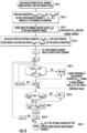
- Fig. 6 is a flow chart for the process of determining the optimum stented lumen contour according to the embodiment of the invention described above, which uses a normality rating of: 1 ⁇ L n ⁇ K for each image cross section.
- ( i ) again indicates segment number
- mm is the counting index
- kk is the stored index
- N is the total number of segments.
- the computations begin with the most distal frame and the optimal diameters are determined by the scaling rule described by Eqn. 1.
- the inclusion of the normality rating permits expansion of the stent in a distal segment beyond the maximum diameter measured in the current segment, if the normality rating L n in a nearby cross section is lower.
- the best reference diameter for a given segment is chosen as the maximum diameter in the closest proximal segment with a better normality rating.
- the maximum diameter condition is included to compensate for errors in the scaled diameters that result from branches narrowed by ostial disease.
- This method of using normality begins, as in the other embodiment, by acquiring the mean diameter of the segments and the side branch data (Step 1).
- the maximum diameter for each inter-branch segment is determined next (Step 2).
- a normality rating is determined at each of the maximum diameter frames (Step 3).
- the tentative optimal diameter is then determined - (Step 4).
- a search is made proximally for a segment in which the D max is more normal and the normality rating, L n is less than a predetermined threshold (Step 5).
- Each segment is searched for the maximum diameter (Step 6). When the frame having a maximum diameter greater than the previous maximum diameter is located, it becomes the new optimum diameter (Step 7). After all the frames are searched (Step 8), the optimal diameter within the segment is determined (Step 9). After all the segments are searched, the optimal diameter for the stented lumen within the vessel has been determined.
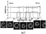
- Fig. 7 shows an example of an optimal lumen contour that was derived from OCT data in accordance with embodiment of the invention described in Fig. 6 .
- the area shown hatched is intended to serve as a guide for choosing the diameter and length of the stent.
- a cross-sectional OCT image at each of the maximum mean-diameter frames is shown for reference.
- the lumen diameter tapers relatively smoothly from a mean of about 2.84 mm to about 2.03 mm, with a moderate step in diameter at the proximal end of the vessel segment due to the presence of a side branch centered on frame 255.
- Good conformance is evident between the computed contour and the lumen diameters of the cross sections in which the vessel intima is thinnest.
- the stent length needed to cover the most severe portion of the lesion is approximately 27 mm; that is, from image frame 125 to image frame 260.
- the user may select locations on the computed contour for setting the preferred contact locations for of the edges of the stent.
- the regions of the image with high normality ratings are displayed in some embodiments as color-coded bars or other indicators.
- the reference frame detection and rating method uses image processing and computer vision algorithms to determine the thickness of the intima-media (IM) and the outer adventitial (OA) regions. This is done using a combination of approaches that work directly on the raw A-line, scan data from the center of the image outward, and the reconstructed frame.
- the system warns the user if the distal contact point is not in a substantially normal region of the vessel.
- an optimal intensity threshold is determined based on the combined image intensity profile along all of the A-lines in each frame.
- the threshold is chosen such that it is at the region of inflection shown by the arrow in the intensity profile of the A-line ( Fig. 8a ).
- This threshold can also be determined by computing the mean intensity value corresponding to a region at a fixed distance (e.g., about 0.56 mm) from the lumen wall. This distance corresponds to the intima-media (IM) region as measured in histology studies. For frames with plaque, there is a thickening of the intensity profile ( Fig. 8b ), which appropriately modifies the threshold value.
- An intensity threshold value that is within a tolerance factor of the inflection point is used to create a binary image with foreground and background separated.
- the foreground of the binary image corresponds to the IM region, whose thickness is measured.
- the average thickness of the IM region indicates the degree of normality. Frames with plaque have a thickened IM region while normal, non-diseased frames have a uniform small IM thickness.
- A-line patch is then cross-correlated, using normalized cross-correlation, with the entire A-line data set and the correlation numbers combined. This process is repeated with the next overlapping A-line patch until every A-line patch is cross-correlated across the entire A-line data.
- A-lines that have a lower correlation number compared to neighboring A-lines indicate non-uniformity, implying the presence of plaque.
- a normal non-plaque frame will ideally have a uniform correlation number across all A-lines.
- the blackened area in the graph corresponds to the region of guidewire shadow.
- a structure similarity metric (SSIM) such as that of Z. Wang et al. in "Image quality assessment: From error visibility to structural similarity ", IEEE Trans. Image Proc, vol 14, no 4, 2004 which measures intensity similarity along with cross-correlation will also provide uniformity characteristics that can be used to distinguish between normal and diseased frames.
- the Wang approach uses the mean and standard deviation of intensities in a window centered at each pixel in two adjacent patches to compute a metric for perceptual change in the structure between the two patches. Frames that have a more uniform SSIM across all patches tend to be normal while those with plaque will have non-uniform SSIM values.
- a basic Gabor filter (Eqn. 4) is a Gaussian filter modulated with a sinusoid function. It behaves as a band-pass filter and can be oriented in different radial directions around the vessel image. The Gaussian is directed along different predetermined orientations by varying the phase term in the equation below, to capture the characteristic specular regions that are seen in the OA regions of normal frames.
- ⁇ o is the frequency
- ⁇ is the phase
- ⁇ x and ⁇ y are the Gaussian envelope parameters.
- a set of OA regions is identified by the user and a Gabor filter is applied to the set.
- the filter parameters such as the ⁇ , ⁇ x and ⁇ y are varied across a wide range of values.
- the set of parameters that give the largest response to the OA region, with a low response to the IM region, is selected as the best set of parameters to filter the OA region. Once these optimal parameters are determined, they can be used for all datasets.
- a major distinguishing characteristic between the IM and OA region in normal frames is the presence of specular features indicating the presence of loose collagen or perivascular fat in the adventitia. The filter, once tuned, attempts to highlight these features while suppressing all others.
- the resulting IM region and the specular OA region are highlighted with high intensity color compared to the background.
- two sets of contours are developed on the filtered image; one from the center of the image outward, and the other from the outside boundary of the image inward. That is, two sets of contours are being developed, one attempting to define the boundary between the IM and the OA moving from the center outward, and one moving from the outside inward.
- the contour propagates based on the underlying image intensity and texture characteristics.
- the image is filtered, highlighting the IM and OA texture.
- the IM contour propagates with a constant speed when the underlying region has homogeneous texture, characteristic of the IM region. It slows and stops its propagation when it reaches regions with texture characteristic of the OA region.
- the OA contour which starts from the outer boundary of the image, propagates through noise until it reaches the OA texture region, at which point it slows and stops.
- the inner contour is propagated outward from the lumen boundary, which has already been detected by standard OCT software.
- the step size for the propagation of this contour at each point is determined based on the underlying intensity characteristics at that point in the image; a bright uniform region implies large step, while low intensity and high intensity gradients imply a small step size.
- the contour stops propagating when it reaches an edge gradient that corresponds to the edge of the IM region.
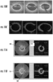
- Fig. 10C depicts the IM and OA regions.
- the outer contour is propagated towards the center from the outer edge of the image.
- each step of this contour is based on the underlying intensity characteristics.
- the step size is large when the intensity value is low and the contour stops propagating when it reaches an edge or a high intensity region. This will typically correspond to the edge of the OA region.
- the outer contour is grown after the inner contour has finished evolving. If the outer contour comes close to the inner contour, which occurs when there are insufficient filtered specular features in the OA region (something that happens typically in plaque), its propagation is terminated.
- the region between the inner and outer contour corresponds to the segmented OA region. Frames with plaque will have thinner OA region while those without plaque, having strong specular features highlighted after the texture filtering step, will be thicker.
- the two contours thereby create a partition or segmentation of the frame into IM and OA region ( Fig. 10b ).
- the ratio of the IM width to the OA width at each A-line provides an indication of normality ( Fig. 10a ). Plaque regions have a high IM and a very low OA region, while normal regions have an almost equal IM and OA width.
- the mean ratio for all A-lines in the frame, ignoring the guide wire region, is an indication of normality as exemplified by the clustering in Fig. 10a . Frames which have no plaque have low mean IM to OA ratio while those with plaque have large IM to OA ratio.
- Fig. 10a shows a scatter plot of the mean IM to OA ratio for a sampling of frames.
- a scatter of the mean of the top 50% of the IM to OA ratio and the top 33% of the IM to OA ratio are also plotted.
- Frames that have an IM to OA mean ratio greater than about 2 are diseased, while those below about 2 are normal. These frames with a ratio of less than about 2 are used as reference frames.
- the various mean ratios provide a measure of normality that is used as a rating for the reference frames.
- the frames at the bottom are the output of the filtering and contour growing steps and show a partitioning of IM and OA. This is used to compute the IM to OA ratio for that frame.
- the frame with plaque shows a smaller OA thickness overall, hence its IM to OA ratio is much higher than the frames which do not have plaque.
- a rating of 1 to 5 is provided for each frame, where 1 indicates an image frame of normal tissue and 5 indicates an image frame of diseased tissue.
- the rating is based on the number of quadrants in which the IM region has a thickness above a certain threshold.
- the frame shown in Fig. 11a is rated 1, while the one in Fig. 1 1b is rated 5.
- the inner 100 and outer 110 contours are the inner and outer contours that segment the IM and OA regions.
- the average IM thickness in each quadrant is calculated based on the inner contour. A thick IM in all quadrants indicates disease, and is given a lower rating.
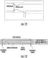
- the computed stent profile is compared with the lumen diameter to determine an index value that provides a measure of error or deviation between the computed ideal profile and the current lumen profile (see Figs. 12 and 13 ).
- the percentage difference between the computed stent profile area and the current lumen area is calculated.
- Stent expansion error index (Arealdeal - Areacurrent)/Areacurrent Eqn. 5
- the error computed at each frame is combined to give a single index for the entire pullback. A lower number will indicate a smaller error ( Fig. 13 ).
- an embodiment of the graphic interface 210 of the system includes a number of panels or subscreens.
- the first panel 214 is a longitudinal section of the vessel being imaged by OCT.
- the light areas 218 denote the walls of the vessel lumen, while the black area 219 is the lumen of the vessel.
- the second panel 222 is a cross section of the vessel shown at the location in the first panel 214 indicated by the white vertical line 226.
- the vessel lumen, as detected by the system or a component thereof, is indicated by the dotted segmented boundary 230.
- the shadow 234 in the image is the shadow caused by a guidewire used to direct the probe.
- the center of the probe 238 is imaged as the white dot 242 surrounded by concentric circles.
- the brightest concentric circle 246 is a titanium oxide calibration layer within the wall of the probe.
- the diagonal line with dots 250 represents the orientation of the image cut plane through the longitudinal axis of the vessel.
- the maximum 251 and minimum 252 diameters are displayed.
- a series of control boxes 253 are displayed that allow the operator to manipulate the image in various ways.
- the third panel 254 is a silhouette representation of the lumen of the vessel in which the interior of the lumen is in darker [256] and the exterior of the lumen is in lighter [257].
- the vertical black regions 258 (only one labeled for clarity) or bars are side branches, which, regardless of their actual orientation as they leave the lumen, are depicted depending vertically from the lumen.
- the width of a vertical black region is a measure of the width of the side branch.
- the fourth panel 262 is an information panel which indicates what is being shown and any measurements made on the lumen image in the second panel 222.
- the area of the lumen is calculated and the maximum and minimum diameter measurements displayed.
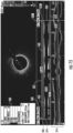
- the user has moved the cross section location indicator (shown as line 287 at about 45 mm in the cross section frame 214) and has indicated that the MLA is to be calculated by checking the MLA box 273 in panel four.
- the system generates a distal boundary marker 274 and a proximal boundary marker 278 and allows the user to position each of those lines separately, where desired, by dragging and dropping each line.
- Panel three indicates where the distal and proximal boundaries are located 282, 283 and displays the target lumen diameter for a given lumen region (white hashed lines) 286.
- the target lumen diameter is largest the size of the vessel that should not be exceeded by a stent diameter because of the possibility of rupturing the vessel.
- the white hashed lines step-down (see for example, 290) at a branch.
- the system shades in region 294, such as with hatching or a contrasting color, as the difference between the actual lumen wall and the target lumen diameter shown with the hashed white line.
- the system displays the distance between the proximal boundary and the distal boundary indicators 296.
- the software can be configured such that as part of a given user interface a difference between an actual lumen wall and a target lumen diameter is displayed using a visual indicator.
- the user has moved the lower 274 and upper 278 boundary markers and the system has recalculated the MLA for this new range and displayed it 300 in the panel.
- the system recalculates the difference between the distal and proximal boundary indicators and displays this measurement 296'.
- the user can continue to try various locations for the distal and proximal boundary indicators ( Fig. 17 ), to make various measurements so as to be able to judge the best location to put the stent, what length the stent should be, and what diameter the stent should be.
- the OCT representation of the vessel and the lumen are configured as a deformable or modifiable representation that allows testing different stent placement scenarios.
- the user can determine if more than one stent is required; whether the stent will block too many branch vessels; and whether the position of the ends of the stent ("the landing zones") will result in their being placed in an area of stenosis.
- the system also labels 297, 297' the diameters of the vessel at each of the boundary indicators 282, 282'.
- the two numbers present are current vessel lumen diameter (smaller number) and target lumen diameter (greater number).
- the system can also determine the target stent diameters of the stent ends.
- the target stent profile is calculated using the diameters of the vessel lumen.
- the algorithm makes several assumptions. First, the diameter of a lumen segment, which is the lumen between branches, is constant. As the lumen crosses the branches, the diameter of the lumen decreases so that the proximal diameter of the lumen is greater than the distal diameter. This incremental decrease in lumen diameter between lumen segments is proportional to the branch diameter between the lumen segments.
- the software-based implementation of the formula and diameter calculations and other steps described herein includes an alert that warn the user that the ends of the stent are being placed in an area of lipid or calcium stenosis that can be ruptured.
- the diameter of the target stent profile in a segment with the distal or proximal stent boundary is substantially equal to the actual of the lumen at that distal or proximal boundary.
- the difference in the area between the proximal and distal boundaries is distributed among the segments between the two boundaries in proportion to the branch diameters between the segments. This means that the decrease in area between two segments is proportional to the diameter of the branch between the two segments.
- the stent profile is a straight line connecting the two ends and the two ends are of the same diameter. If the diameter of the lumen of the proximal cursor is less than the diameter of the distal cursor, then stent profile is a straight line connecting the two ends, but the two ends have different diameters.
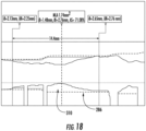
- Fig. 18 shown is a portion of the graphic interface depicting the difference between the target stent profile 310 and target lumen diameter profile 286.
- the data from an OCT scan of the lumen is collected or retrieved from a database and the target lumen profile is produced by the system, methods, or components otherwise described.
- the system then calculates the target stent diameter using one or more algorithm and methods described herein. Alternatively, the system can try different stent placements based on user selected locations in the stent in the user interface.
- an algorithm is generally defined as a self-consistent sequence of operations leading to a desired result.
- the operations performed as method steps or otherwise described herein are those requiring physical manipulations of physical quantities. Usually, though not necessarily, these quantities take the form of electrical or magnetic signals capable of being stored, transferred, combined, transformed, compared, and otherwise manipulated.
- the present invention in some embodiments, also relates to an apparatus for performing the operations herein.
- This apparatus may be specially constructed for the required purposes, or it may comprise a general purpose computer selectively activated or reconfigured by a computer program stored in the computer.
- Embodiments of the invention may be embodied in many different forms, including, but in no way limited to, computer program logic for use with a processor (e.g., a microprocessor, microcontroller, digital signal processor, or general purpose computer), programmable logic for use with a programmable logic device, (e.g., a Field Programmable Gate Array (FPGA) or other PLD), discrete components, integrated circuitry (e.g., an Application Specific Integrated Circuit (ASIC)), or any other means including any combination thereof.
- a processor e.g., a microprocessor, microcontroller, digital signal processor, or general purpose computer
- programmable logic for use with a programmable logic device, (e.g., a Field Programmable Gate Array (FPGA) or other PLD), discrete components, integrated circuitry (e.g., an Application Specific Integrated Circuit (ASIC)), or any other means including any combination thereof.
- FPGA Field Programmable Gate Array
- ASIC Application Specific Integrated Circuit
- some or all of the processing of the data collected using an OCT probe and the processor-based system is implemented as a set of computer program instructions that is converted into a computer executable form, stored as such in a computer readable medium, and executed by a microprocessor under the control of an operating system.
- query response and input data are transformed into processor understandable instructions suitable for generating OCT data, generating and propagating contours, filtering data, displaying regions, area and volume measurements, performing a medical device-specific action based on or in response to a parameter, and other features and embodiments described above.
- Source code may include a series of computer program instructions implemented in any of various programming languages (e.g., an object code, an assembly language, or a high-level language such as Fortran, C, C++, JAVA, or HTML) for use with various operating systems or operating environments.
- the source code may define and use various data structures and communication messages.
- the source code may be in a computer executable form (e.g., via an interpreter), or the source code may be converted (e.g., via a translator, assembler, or compiler) into a computer executable form.
- the computer program may be fixed in any form (e.g., source code form, computer executable form, or an intermediate form) either permanently or transitorily in a tangible storage medium, such as a semiconductor memory device (e.g., a RAM, ROM, PROM, EEPROM, or Flash-Programmable RAM), a magnetic memory device (e.g., a diskette or fixed disk), an optical memory device (e.g., a CD-ROM), a PC card (e.g., PCMCIA card), or other memory device.
- a semiconductor memory device e.g., a RAM, ROM, PROM, EEPROM, or Flash-Programmable RAM
- a magnetic memory device e.g., a diskette or fixed disk
- an optical memory device e.g., a CD-ROM
- PC card e.g., PCMCIA card
- the computer program may be fixed in any form in a signal that is transmittable to a computer using any of various communication technologies, including, but in no way limited to, analog technologies, digital technologies, optical technologies, wireless technologies (e.g., Bluetooth), networking technologies, and internetworking technologies.
- the computer program may be distributed in any form as a removable storage medium with accompanying printed or electronic documentation (e.g., shrink-wrapped software), preloaded with a computer system (e.g., on system ROM or fixed disk), or distributed from a server or electronic bulletin board over the communication system (e.g., the Internet or World Wide Web).
- Programmable logic may be fixed either permanently or transitorily in a tangible storage medium, such as a semiconductor memory device (e.g., a RAM, ROM, PROM, EEPROM, or Flash-Programmable RAM), a magnetic memory device (e.g., a diskette or fixed disk), an optical memory device (e.g., a CD-ROM), or other memory device.
- a semiconductor memory device e.g., a RAM, ROM, PROM, EEPROM, or Flash-Programmable RAM
- a magnetic memory device e.g., a diskette or fixed disk
- an optical memory device e.g., a CD-ROM
- the programmable logic may be fixed in a signal that is transmittable to a computer using any of various communication technologies, including, but in no way limited to, analog technologies, digital technologies, optical technologies, wireless technologies (e.g., Bluetooth), networking technologies, and internetworking technologies.
- the programmable logic may be distributed as a removable storage medium with accompanying printed or electronic documentation (e.g., shrink-wrapped software), preloaded with a computer system (e.g., on system ROM or fixed disk), or distributed from a server or electronic bulletin board over the communication system (e.g., the Internet or World Wide Web).
- printed or electronic documentation e.g., shrink-wrapped software
- a computer system e.g., on system ROM or fixed disk
- server or electronic bulletin board e.g., the Internet or World Wide Web
- a module refers to software, hardware, or firmware suitable for performing a specific data processing or data transmission task.
- a module refers to a software routine, program, or other memory resident application suitable for receiving, transforming, routing and processing instructions, or various types of data such as measured probe parameters, quantitative parameters, encoding schemes, decoding schemes, calibration data, probe lengths, probe measurements, probe intensity, and other information of interest.
- Computers and computer systems described herein may include operatively associated computer-readable media such as memory for storing software applications used in obtaining, processing, storing and/or communicating data. It can be appreciated that such memory can be internal, external, remote or local with respect to its operatively associated computer or computer system.
- Memory may also include any means for storing software or other instructions including, for example and without limitation, a hard disk, an optical disk, floppy disk, DVD (digital versatile disc), CD (compact disc), memory stick, flash memory, ROM (read only memory), RAM (random access memory), DRAM (dynamic random access memory), PROM (programmable ROM), EEPROM (extended erasable PROM), and/or other like computer-readable media.
- a hard disk an optical disk, floppy disk, DVD (digital versatile disc), CD (compact disc), memory stick, flash memory, ROM (read only memory), RAM (random access memory), DRAM (dynamic random access memory), PROM (programmable ROM), EEPROM (extended erasable PROM), and/or other like computer-readable media.
- computer-readable memory media applied in association with embodiments of the invention described herein may include any memory medium capable of storing instructions executed by a programmable apparatus. Where applicable, method steps described herein may be embodied or executed as instructions stored on a computer-readable memory medium or memory media. These instructions may be software embodied in various programming languages such as C++, C, Java, and/or a variety of other kinds of software programming languages that may be applied to create instructions in accordance with embodiments of the invention.
- compositions are described as having, including, or comprising specific components, or where processes are described as having, including or comprising specific process steps, it is contemplated that compositions of the present teachings also consist essentially of, or consist of, the recited components, and that the processes of the present teachings also consist essentially of, or consist of, the recited process steps.
- each intervening value between the upper and lower limits of that range or list of values is individually contemplated and is encompassed within the invention as if each value were specifically enumerated herein.
- smaller ranges between and including the upper and lower limits of a given range are contemplated and encompassed within the invention.
- the listing of exemplary values or ranges is not a disclaimer of other values or ranges between and including the upper and lower limits of a given range.
- the present invention also provides a method for sizing a stent for placement in a lumen of a vessel comprising:
- the maximum diameter of a segment is determined in response to the measured diameter of the segment, the calculated diameter of the segment and a quality of the segment.
- D is the diameter of the segment
- D b is a diameter of the branch
- ⁇ is an exponent.
- ⁇ has a value between about 2.0 and about 3.0.
- normalcy of the tissue is determined by a method selected from the group of automated tissue characterization, user identification and morphology.
- the method of automated tissue characterization includes cross-correlating an optical coherence tomography signal between adjacent regions of the vessel.
- the method of automated tissue characterization uses IM to OA ratios.
- images of the vessel segments are first filtered with a Gabor filter.
- the method of automated tissue characterization uses frame based intensity profiles.
- the method further comprises determining where in the vessel the stent should make contact by determining an amount of disease present in the vessel.
- the present invention also provides an apparatus for sizing a stent for placement in a vessel, the apparatus comprising:
- the processor determines the maximum diameter of a segment in response to the measured diameter of the segment, the calculated diameter of the segment and a quality of the segment.
- ⁇ has a value between about 2.0 and about 3.0.
- the apparatus determines a normalcy of tissue by a method selected from the group consisting of automated tissue characterization, user identification and morphology.
- automated tissue characterization utilizes cross-correlation of the OCT signal between adjacent regions of the vessel.
- automated tissue characterization uses IM to OA ratios.
- the processor first filters image data of the vessel segments using a Gabor filter.
- the processor performs automated tissue characterization using frame based intensity profiles.
- the processor determines where in the vessel the stent should make contact by determining an amount of disease present in the vessel.
- the present invention also provides a processor-based method of displaying a representation of a section of a blood vessel, the method comprising:
- the method further comprises displaying, in a second panel, a longitudinal view of the of the section of the blood vessel, wherein the first axis corresponds to a diameter value, wherein the second axis corresponds to a position along the section of the blood vessel and a branch of the blood vessel as a bar.
- the width of the bar is sized such that it equals the width of the branch and further comprising displaying a target lumen diameter.
- the method further comprises displaying a third panel comprising a cross-sectional image view of the blood vessel.
- the method further comprises displaying an OCT generated representation of a vessel configured to provide feedback to a user in response to different stent placement scenarios.
- the method further comprises the step of displaying a difference between an actual lumen wall and a target lumen diameter using a visual indicator.
- the method further comprises the step of displaying a proximal reference boundary and a distal reference boundary.
- the method further comprises the step of displaying a distance between a proximal reference boundary and a distal reference boundary.
- the method further comprises the step of displaying a percentage of diameter stenosis in the first panel.
Landscapes
- Health & Medical Sciences (AREA)
- Life Sciences & Earth Sciences (AREA)
- Engineering & Computer Science (AREA)
- Public Health (AREA)
- General Health & Medical Sciences (AREA)
- Medical Informatics (AREA)
- Biomedical Technology (AREA)
- Surgery (AREA)
- Veterinary Medicine (AREA)
- Animal Behavior & Ethology (AREA)
- Heart & Thoracic Surgery (AREA)
- Pathology (AREA)
- Physics & Mathematics (AREA)
- Biophysics (AREA)
- Molecular Biology (AREA)
- Nuclear Medicine, Radiotherapy & Molecular Imaging (AREA)
- Epidemiology (AREA)
- Primary Health Care (AREA)
- Radiology & Medical Imaging (AREA)
- Vascular Medicine (AREA)
- Oral & Maxillofacial Surgery (AREA)
- Cardiology (AREA)
- Dentistry (AREA)
- Physiology (AREA)
- Urology & Nephrology (AREA)
- Transplantation (AREA)
- Data Mining & Analysis (AREA)
- Databases & Information Systems (AREA)
- Endoscopes (AREA)
- Apparatus For Radiation Diagnosis (AREA)
- Media Introduction/Drainage Providing Device (AREA)
- Ultra Sonic Daignosis Equipment (AREA)
- Prostheses (AREA)
Applications Claiming Priority (4)
| Application Number | Priority Date | Filing Date | Title |
|---|---|---|---|
| US201261736226P | 2012-12-12 | 2012-12-12 | |
| EP17183053.2A EP3272282B1 (de) | 2012-12-12 | 2013-03-12 | Vorrichtung zur automatisierten bestimmung einer lumenkontur eines blutgefässes |
| PCT/US2013/030328 WO2014092755A1 (en) | 2012-12-12 | 2013-03-12 | Method and apparatus for automated determination of a lumen contour of a blood vessel |
| EP13716492.7A EP2931115B1 (de) | 2012-12-12 | 2013-03-12 | Vorrichtung zur automatisierten bestimmung einer lumenkontur eines blutgefässes |
Related Parent Applications (2)
| Application Number | Title | Priority Date | Filing Date |
|---|---|---|---|
| EP13716492.7A Division EP2931115B1 (de) | 2012-12-12 | 2013-03-12 | Vorrichtung zur automatisierten bestimmung einer lumenkontur eines blutgefässes |
| EP17183053.2A Division EP3272282B1 (de) | 2012-12-12 | 2013-03-12 | Vorrichtung zur automatisierten bestimmung einer lumenkontur eines blutgefässes |
Publications (2)
| Publication Number | Publication Date |
|---|---|
| EP4445837A2 true EP4445837A2 (de) | 2024-10-16 |
| EP4445837A3 EP4445837A3 (de) | 2024-12-25 |
Family
ID=48096170
Family Applications (3)
| Application Number | Title | Priority Date | Filing Date |
|---|---|---|---|
| EP24196775.1A Pending EP4445837A3 (de) | 2012-12-12 | 2013-03-12 | Vorrichtung zur automatisierten bestimmung einer lumenkontur eines blutgefässes |
| EP13716492.7A Active EP2931115B1 (de) | 2012-12-12 | 2013-03-12 | Vorrichtung zur automatisierten bestimmung einer lumenkontur eines blutgefässes |
| EP17183053.2A Active EP3272282B1 (de) | 2012-12-12 | 2013-03-12 | Vorrichtung zur automatisierten bestimmung einer lumenkontur eines blutgefässes |
Family Applications After (2)
| Application Number | Title | Priority Date | Filing Date |
|---|---|---|---|
| EP13716492.7A Active EP2931115B1 (de) | 2012-12-12 | 2013-03-12 | Vorrichtung zur automatisierten bestimmung einer lumenkontur eines blutgefässes |
| EP17183053.2A Active EP3272282B1 (de) | 2012-12-12 | 2013-03-12 | Vorrichtung zur automatisierten bestimmung einer lumenkontur eines blutgefässes |
Country Status (8)
| Country | Link |
|---|---|
| US (2) | US11923067B2 (de) |
| EP (3) | EP4445837A3 (de) |
| JP (3) | JP6336471B2 (de) |
| CN (2) | CN108836280B (de) |
| AU (2) | AU2013360356B2 (de) |
| CA (1) | CA2892810C (de) |
| ES (2) | ES2641487T3 (de) |
| WO (1) | WO2014092755A1 (de) |
Families Citing this family (60)
| Publication number | Priority date | Publication date | Assignee | Title |
|---|---|---|---|---|
| US10210956B2 (en) | 2012-10-24 | 2019-02-19 | Cathworks Ltd. | Diagnostically useful results in real time |
| EP2919659B1 (de) | 2012-11-19 | 2021-03-17 | Lightlab Imaging, Inc. | Multimodal-abbildungssysteme |
| US20150305631A1 (en) * | 2014-04-25 | 2015-10-29 | Medtronic, Inc. | Real-Time Relationship Between Geometries of an Instrument and a Structure |
| EP3140757B1 (de) * | 2014-05-05 | 2020-06-24 | Siemens Healthcare GmbH | Verfahren und system zur nichtinvasiven funktionellen beurteilung von koronararterienstenose anhand von strömungsberechnungen bei modellen basierend auf erkrankten patienten und hypothetisch normalen anatomischen modellen |
| ES2744900T3 (es) * | 2014-07-24 | 2020-02-26 | Lightlab Imaging Inc | Visualización de endoprótesis vasculares y vasos sanguíneos y procedimientos de diagnóstico |
| EP3229695B1 (de) * | 2014-12-10 | 2023-07-19 | Koninklijke Philips N.V. | Systeme zur vorhersage von in-stent-restenose |
| JP6669720B2 (ja) * | 2015-02-25 | 2020-03-18 | テルモ株式会社 | 画像診断装置、その作動方法、プログラム及びコンピュータ可読記憶媒体 |
| JP6869951B2 (ja) | 2015-04-16 | 2021-05-12 | ジェンテュイティ・リミテッド・ライアビリティ・カンパニーGentuity, LLC | 撮像システム |
| US10109058B2 (en) | 2015-05-17 | 2018-10-23 | Lightlab Imaging, Inc. | Intravascular imaging system interfaces and stent detection methods |
| US10222956B2 (en) | 2015-05-17 | 2019-03-05 | Lightlab Imaging, Inc. | Intravascular imaging user interface systems and methods |
| US9996921B2 (en) | 2015-05-17 | 2018-06-12 | LIGHTLAB IMAGING, lNC. | Detection of metal stent struts |
| US10646198B2 (en) | 2015-05-17 | 2020-05-12 | Lightlab Imaging, Inc. | Intravascular imaging and guide catheter detection methods and systems |
| US10140712B2 (en) | 2015-05-17 | 2018-11-27 | Lightlab Imaging, Inc. | Detection of stent struts relative to side branches |
| US10338795B2 (en) * | 2015-07-25 | 2019-07-02 | Lightlab Imaging, Inc. | Intravascular data visualization and interface systems and methods |
| WO2017040484A1 (en) | 2015-08-31 | 2017-03-09 | Gentuity, Llc | Imaging system includes imaging probe and delivery devices |
| EP3871589B1 (de) | 2015-11-18 | 2025-03-05 | Lightlab Imaging, Inc. | Erkennung von stentstreben relativ zu seitenabzweigungen |
| EP3381014B1 (de) | 2015-11-23 | 2020-12-16 | Lightlab Imaging, Inc. | Nachweis und validierung von schatten auf intravaskulären bildern |
| US10593037B2 (en) | 2016-04-14 | 2020-03-17 | Lightlab Imaging, Inc. | Method, apparatus, and system to identify branches of a blood vessel |
| WO2017201026A1 (en) | 2016-05-16 | 2017-11-23 | Lightlab Imaging, Inc. | Intravascular absorbable stent detection and diagnostic methods and systems |
| EP3461253B1 (de) | 2016-05-16 | 2023-08-09 | Cathworks Ltd. | Auswahl von blutgefässpfaden aus bildern |
| US11883107B2 (en) | 2016-09-28 | 2024-01-30 | Lightlab Imaging, Inc. | Stent planning systems and methods using vessel representation obtained via intravascular probe by determining stent effectiveness score and fractional flow reserve |
| WO2019070702A1 (en) | 2017-10-02 | 2019-04-11 | Lightlab Imaging, Inc. | INTRAVASCULAR DATA COLLECTION PROBES AND ASSOCIATED ASSEMBLIES |
| EP3700406A4 (de) | 2017-11-28 | 2021-12-29 | Gentuity LLC | Bildgebungssystem |
| CN108335284B (zh) * | 2018-01-09 | 2022-06-28 | 北京理工大学 | 一种冠脉血管中心线匹配方法和系统 |
| EP3766079A1 (de) * | 2018-03-14 | 2021-01-20 | Koninklijke Philips N.V. | Bewertung von intravaskulären läsionen und stenteinführung in der medizinischen intraluminalen ultraschallbildgebung |
| EP3764915B1 (de) * | 2018-03-15 | 2025-07-16 | Koninklijke Philips N.V. | Bestimmung und visualisierung anatomischer landmarken für intraluminale läsionsbeurteilung und behandlungsplanung |
| JP7075371B2 (ja) | 2018-05-03 | 2022-05-25 | キヤノン ユーエスエイ,インコーポレイテッド | マルチプルイメージングモダリティにわたって関心領域を強調するためのデバイス、システム、および方法 |
| ES3013537T3 (en) * | 2018-05-29 | 2025-04-14 | Lightlab Imaging Inc | Stent expansion display, systems, and methods |
| CN109009001B (zh) * | 2018-07-02 | 2019-07-09 | 博动医学影像科技(上海)有限公司 | 血管压力差修正方法、装置和设备 |
| US12262872B2 (en) | 2018-09-17 | 2025-04-01 | Gentuity, Llc | Imaging system with optical pathway |
| US12440188B2 (en) * | 2018-10-26 | 2025-10-14 | Philips Image Guided Therapy Corporation | Graphical longitudinal display for intraluminal ultrasound imaging and associated devices, systems, and methods |
| CN119762473A (zh) | 2019-01-13 | 2025-04-04 | 光实验成像公司 | 用于动脉图像区域及其特征的分类的系统和方法 |
| WO2020154904A1 (zh) * | 2019-01-29 | 2020-08-06 | 深圳市科曼医疗设备有限公司 | 一种超声图像血管直径自动测量方法 |
| JP7568636B2 (ja) * | 2019-03-17 | 2024-10-16 | ライトラボ・イメージング・インコーポレーテッド | 動脈の撮像・評価のシステム及び方法並びに関連するユーザインタフェースに基づくワークフロー |
| US12364385B2 (en) | 2019-04-30 | 2025-07-22 | Gentuity, Llc | Imaging probe with fluid pressurization element |
| JP2022533212A (ja) | 2019-05-21 | 2022-07-21 | ジェンテュイティ・リミテッド・ライアビリティ・カンパニー | 患者のoctガイド処置システム及び方法 |
| JP7157098B2 (ja) * | 2019-10-30 | 2022-10-19 | i-PRO株式会社 | 血管内視鏡システムおよび血管径測定方法 |
| WO2021115958A1 (en) * | 2019-12-10 | 2021-06-17 | Koninklijke Philips N.V. | Intraluminal image-based vessel diameter determination and associated devices, systems, and methods |
| US20230045488A1 (en) * | 2020-01-06 | 2023-02-09 | Philips Image Guided Therapy Corporation | Intraluminal imaging based detection and visualization of intraluminal treatment anomalies |
| EP4099910B1 (de) * | 2020-02-04 | 2025-05-07 | Koninklijke Philips N.V. | Automatische intraluminale abbildungsbasierte ziel- und referenzbildrahmenerfassung |
| TWI740600B (zh) * | 2020-08-10 | 2021-09-21 | 台灣基督長老教會馬偕醫療財團法人馬偕紀念醫院 | 用以評估動脈阻塞程度的方法 |
| CN114145733B (zh) * | 2020-09-07 | 2024-10-01 | 先健科技(深圳)有限公司 | 测量装置、测量系统和测量方法 |
| NL2026715B1 (en) * | 2020-10-20 | 2022-06-16 | Medis Ass B V | Method of determining vessel fluid flow velocity |
| JP7801065B2 (ja) * | 2021-03-25 | 2026-01-16 | テルモ株式会社 | コンピュータプログラム、情報処理方法及び情報処理装置 |
| US12315076B1 (en) | 2021-09-22 | 2025-05-27 | Cathworks Ltd. | Four-dimensional motion analysis of a patient's coronary arteries and myocardial wall |
| US12076118B2 (en) * | 2021-10-01 | 2024-09-03 | Canon U.S.A., Inc. | Devices, systems, and methods for detecting external elastic lamina (EEL) from intravascular OCT images |
| CN118450850A (zh) * | 2021-10-08 | 2024-08-06 | 波士顿科学国际有限公司 | 用于自动病变评估的医疗装置系统 |
| USD1083949S1 (en) | 2021-10-15 | 2025-07-15 | Lightlab Imaging, Inc. | Display screen or portion thereof with graphical user interface |
| US20230190227A1 (en) * | 2021-12-16 | 2023-06-22 | Philips Image Guided Therapy Corporation | Plaque burden indication on longitudinal intraluminal image and x-ray image |
| IL314862A (en) | 2022-02-10 | 2024-10-01 | Cathworks Ltd | System and method for machine-learning based sensor analysis and vascular tree segmentation |
| CN115153503B (zh) * | 2022-06-23 | 2025-04-29 | 北京悦唯医疗科技有限责任公司 | 一种血管直径测量探头及装置 |
| JP2025531150A (ja) * | 2022-09-14 | 2025-09-19 | ボストン サイエンティフィック サイムド,インコーポレイテッド | 血管内超音波による自動病変評価システムのためのグラフィカルユーザインターフェース |
| WO2024059136A1 (en) * | 2022-09-14 | 2024-03-21 | Boston Scientific Scimed, Inc. | Graphical user interface for intravascular ultrasound stent display |
| WO2024071121A1 (ja) * | 2022-09-28 | 2024-04-04 | テルモ株式会社 | コンピュータプログラム、情報処理方法、及び情報処理装置 |
| US20240169524A1 (en) * | 2022-11-23 | 2024-05-23 | Case Western Reserve University | Prediction of stent expansion using finite element modeling and machine learning |
| CN115869013B (zh) * | 2022-12-08 | 2024-07-12 | 合肥合滨智能机器人有限公司 | 一种用于血管超声自主扫查的血管定位和导航方法 |
| IL326434A (en) | 2023-08-09 | 2026-04-01 | Cathworks Ltd | User interface and signal leakage testing for vascular index measurement |
| IL326432A (en) | 2023-08-09 | 2026-04-01 | Cathworks Ltd | Coronary artery assessment after PCI |
| CN117179894B (zh) * | 2023-11-07 | 2024-03-15 | 北京唯迈医疗设备有限公司 | 介入手术支架辅助选型和定位的装置、系统和存储介质 |
| US12499646B1 (en) | 2024-06-12 | 2025-12-16 | Cathworks Ltd. | Three-dimensional sizing tool for cardiac assessment |
Citations (1)
| Publication number | Priority date | Publication date | Assignee | Title |
|---|---|---|---|---|
| US20110071404A1 (en) | 2009-09-23 | 2011-03-24 | Lightlab Imaging, Inc. | Lumen Morphology and Vascular Resistance Measurements Data Collection Systems, Apparatus and Methods |
Family Cites Families (133)
| Publication number | Priority date | Publication date | Assignee | Title |
|---|---|---|---|---|
| US5477858A (en) | 1986-07-30 | 1995-12-26 | Siemens Medical Systems, Inc. | Ultrasound blood flow/tissue imaging system |
| US5662109A (en) | 1990-12-14 | 1997-09-02 | Hutson; William H. | Method and system for multi-dimensional imaging and analysis for early detection of diseased tissue |
| US5054492A (en) | 1990-12-17 | 1991-10-08 | Cardiovascular Imaging Systems, Inc. | Ultrasonic imaging catheter having rotational image correlation |
| WO1992019930A1 (en) | 1991-04-29 | 1992-11-12 | Massachusetts Institute Of Technology | Method and apparatus for optical imaging and measurement |
| US6134003A (en) | 1991-04-29 | 2000-10-17 | Massachusetts Institute Of Technology | Method and apparatus for performing optical measurements using a fiber optic imaging guidewire, catheter or endoscope |
| US5748598A (en) | 1995-12-22 | 1998-05-05 | Massachusetts Institute Of Technology | Apparatus and methods for reading multilayer storage media using short coherence length sources |
| US5956355A (en) | 1991-04-29 | 1999-09-21 | Massachusetts Institute Of Technology | Method and apparatus for performing optical measurements using a rapidly frequency-tuned laser |
| US6485413B1 (en) | 1991-04-29 | 2002-11-26 | The General Hospital Corporation | Methods and apparatus for forward-directed optical scanning instruments |
| US6501551B1 (en) | 1991-04-29 | 2002-12-31 | Massachusetts Institute Of Technology | Fiber optic imaging endoscope interferometer with at least one faraday rotator |
| US6564087B1 (en) | 1991-04-29 | 2003-05-13 | Massachusetts Institute Of Technology | Fiber optic needle probes for optical coherence tomography imaging |
| US5465147A (en) | 1991-04-29 | 1995-11-07 | Massachusetts Institute Of Technology | Method and apparatus for acquiring images using a ccd detector array and no transverse scanner |
| US6111645A (en) | 1991-04-29 | 2000-08-29 | Massachusetts Institute Of Technology | Grating based phase control optical delay line |
| US5325449A (en) | 1992-05-15 | 1994-06-28 | David Sarnoff Research Center, Inc. | Method for fusing images and apparatus therefor |
| US5509093A (en) | 1993-10-13 | 1996-04-16 | Micron Optics, Inc. | Temperature compensated fiber fabry-perot filters |
| US5531227A (en) | 1994-01-28 | 1996-07-02 | Schneider Medical Technologies, Inc. | Imaging device and method |
| US5797849A (en) | 1995-03-28 | 1998-08-25 | Sonometrics Corporation | Method for carrying out a medical procedure using a three-dimensional tracking and imaging system |
| US5619368A (en) | 1995-05-16 | 1997-04-08 | Massachusetts Inst. Of Technology | Optical frequency shifter |
| WO1997001167A1 (en) | 1995-06-21 | 1997-01-09 | Massachusetts Institute Of Technology | Apparatus and method for accessing data on multilayered optical media |
| US5810007A (en) | 1995-07-26 | 1998-09-22 | Associates Of The Joint Center For Radiation Therapy, Inc. | Ultrasound localization and image fusion for the treatment of prostate cancer |
| US5771895A (en) | 1996-02-12 | 1998-06-30 | Slager; Cornelis J. | Catheter for obtaining three-dimensional reconstruction of a vascular lumen and wall |
| US6148095A (en) | 1997-09-08 | 2000-11-14 | University Of Iowa Research Foundation | Apparatus and method for determining three-dimensional representations of tortuous vessels |
| US5989189A (en) | 1997-10-24 | 1999-11-23 | Mentor Corporation | Ophthalmic ultrasound imaging |
| US20020161351A1 (en) | 1998-09-01 | 2002-10-31 | Samson Wilfred J. | Method and apparatus for treating acute myocardial infarction with selective hypothermic perfusion |
| US6191862B1 (en) | 1999-01-20 | 2001-02-20 | Lightlab Imaging, Llc | Methods and apparatus for high speed longitudinal scanning in imaging systems |
| US6385332B1 (en) | 1999-02-19 | 2002-05-07 | The John P. Roberts Research Institute | Automated segmentation method for 3-dimensional ultrasound |
| US6471656B1 (en) | 1999-06-25 | 2002-10-29 | Florence Medical Ltd | Method and system for pressure based measurements of CFR and additional clinical hemodynamic parameters |
| US6381350B1 (en) | 1999-07-02 | 2002-04-30 | The Cleveland Clinic Foundation | Intravascular ultrasonic analysis using active contour method and system |
| US6445939B1 (en) | 1999-08-09 | 2002-09-03 | Lightlab Imaging, Llc | Ultra-small optical probes, imaging optics, and methods for using same |
| US6785409B1 (en) | 2000-10-24 | 2004-08-31 | Koninklijke Philips Electronics, N.V. | Segmentation method and apparatus for medical images using diffusion propagation, pixel classification, and mathematical morphology |
| DE60141090D1 (de) | 2000-10-30 | 2010-03-04 | Gen Hospital Corp | Optische systeme zur gewebeanalyse |
| US20020115931A1 (en) | 2001-02-21 | 2002-08-22 | Strauss H. William | Localizing intravascular lesions on anatomic images |
| US6768756B2 (en) | 2001-03-12 | 2004-07-27 | Axsun Technologies, Inc. | MEMS membrane with integral mirror/lens |
| US6570659B2 (en) | 2001-03-16 | 2003-05-27 | Lightlab Imaging, Llc | Broadband light source system and method and light source combiner |
| US6552796B2 (en) | 2001-04-06 | 2003-04-22 | Lightlab Imaging, Llc | Apparatus and method for selective data collection and signal to noise ratio enhancement using optical coherence tomography |
| US6585660B2 (en) | 2001-05-18 | 2003-07-01 | Jomed Inc. | Signal conditioning device for interfacing intravascular sensors having varying operational characteristics to a physiology monitor |
| US6697667B1 (en) | 2001-05-31 | 2004-02-24 | Advanced Cardiovascular Systems, Inc. | Apparatus and method for locating coronary sinus |
| US6716178B1 (en) | 2001-05-31 | 2004-04-06 | Advanced Cardiovascular Systems, Inc. | Apparatus and method for performing thermal and laser doppler velocimetry measurements |
| US6706004B2 (en) | 2001-05-31 | 2004-03-16 | Infraredx, Inc. | Balloon catheter |
| US7532920B1 (en) | 2001-05-31 | 2009-05-12 | Advanced Cardiovascular Systems, Inc. | Guidewire with optical fiber |
| US7329223B1 (en) | 2001-05-31 | 2008-02-12 | Abbott Cardiovascular Systems Inc. | Catheter with optical fiber sensor |
| US6879851B2 (en) | 2001-06-07 | 2005-04-12 | Lightlab Imaging, Llc | Fiber optic endoscopic gastrointestinal probe |
| US6947040B2 (en) | 2001-10-23 | 2005-09-20 | Siemens Corporate Research, Inc. | Vessel detection by mean shift based ray propagation |
| US6868736B2 (en) | 2002-02-22 | 2005-03-22 | Sentec Corporation | Ultra-miniature optical pressure sensing system |
| US7937660B2 (en) * | 2002-04-19 | 2011-05-03 | Medtronic Vascular, Inc. | Computer-based methods and structures for stent-graft selection |
| US7134994B2 (en) | 2002-05-20 | 2006-11-14 | Volcano Corporation | Multipurpose host system for invasive cardiovascular diagnostic measurement acquisition and display |
| US6891984B2 (en) | 2002-07-25 | 2005-05-10 | Lightlab Imaging, Llc | Scanning miniature optical probes with optical distortion correction and rotational control |
| US7359554B2 (en) | 2002-08-26 | 2008-04-15 | Cleveland Clinic Foundation | System and method for identifying a vascular border |
| US7693563B2 (en) | 2003-01-30 | 2010-04-06 | Chase Medical, LLP | Method for image processing and contour assessment of the heart |
| US8465452B2 (en) * | 2003-02-21 | 2013-06-18 | 3Dt Holdings, Llc | Devices, systems, and methods for removing stenotic lesions from vessels |
| US20060165270A1 (en) | 2003-02-25 | 2006-07-27 | Jorn Borgert | Intravascular imaging |
| US7241286B2 (en) | 2003-04-25 | 2007-07-10 | Lightlab Imaging, Llc | Flush catheter with flow directing sheath |
| US20100076320A1 (en) | 2003-04-25 | 2010-03-25 | Lightlab Imaging, Llc | Flush catheter with flow directing sheath |
| US7998188B2 (en) * | 2003-04-28 | 2011-08-16 | Kips Bay Medical, Inc. | Compliant blood vessel graft |
| DE10325298B4 (de) | 2003-06-04 | 2007-07-05 | Siemens Ag | Verfahren und Vorrichtung zur Erfassung der Rauigkeit von Gefäßen |
| JP5567246B2 (ja) | 2003-10-27 | 2014-08-06 | ザ ジェネラル ホスピタル コーポレイション | 周波数ドメイン干渉測定を利用して光学撮像を実行する方法および装置 |
| CA2449080A1 (en) | 2003-11-13 | 2005-05-13 | Centre Hospitalier De L'universite De Montreal - Chum | Apparatus and method for intravascular ultrasound image segmentation: a fast-marching method |
| EP1713400B1 (de) | 2004-01-16 | 2012-12-26 | Boston Scientific Scimed, Inc. | Gerät für die medizinische bilddarstellung |
| US20050238067A1 (en) | 2004-04-26 | 2005-10-27 | Choi Youngmin A | Simple fiber optic cavity |
| US7397935B2 (en) | 2004-05-10 | 2008-07-08 | Mediguide Ltd. | Method for segmentation of IVUS image sequences |
| WO2006024015A1 (en) | 2004-08-24 | 2006-03-02 | The General Hospital Corporation | Method and apparatus for imaging of vessel segments |
| US20060095065A1 (en) | 2004-09-24 | 2006-05-04 | Tetsuaki Tanimura | Fluid occluding devices and methods |
| US8983582B2 (en) | 2004-12-20 | 2015-03-17 | Advanced Cardiovascular Systems, Inc. | Methods and apparatuses for positioning within an internal channel |
| US7930014B2 (en) | 2005-01-11 | 2011-04-19 | Volcano Corporation | Vascular image co-registration |
| US8315282B2 (en) | 2005-01-20 | 2012-11-20 | Massachusetts Institute Of Technology | Fourier domain mode locking: method and apparatus for control and improved performance |
| EP2264841B1 (de) | 2005-01-20 | 2016-01-20 | Massachusetts Institute of Technology (MIT) | Verfahren und Vorrichtung zur Modenkopplung |
| JP2008529068A (ja) | 2005-01-24 | 2008-07-31 | ソルラブス、 インコーポレイテッド | 高速に波長スキャンする小型マルチモードレーザ |
| US8054075B2 (en) | 2005-02-03 | 2011-11-08 | The Johns Hopkins University | Method for magnetic resonance imaging using inversion recovery with on-resonant water suppression including MRI systems and software embodying same |
| EP1850735A2 (de) | 2005-02-10 | 2007-11-07 | Lightlab Imaging, Inc. | Optische kohärenztomografievorrichtung und -verfahren |
| US7892177B2 (en) | 2005-02-28 | 2011-02-22 | Scimed Life Systems, Inc. | Systems and methods for estimating the length and position of a stent to be applied within a patient |
| US7415049B2 (en) | 2005-03-28 | 2008-08-19 | Axsun Technologies, Inc. | Laser with tilted multi spatial mode resonator tuning element |
| CN1305448C (zh) | 2005-04-08 | 2007-03-21 | 北京思创贯宇科技开发有限公司 | 一种血管支架定位及术前选取的方法及系统 |
| WO2007002685A2 (en) | 2005-06-24 | 2007-01-04 | Volcano Corporation | Co-registration of graphical image data representing three-dimensional vascular features |
| DE102005032961A1 (de) | 2005-07-14 | 2007-01-18 | Siemens Ag | Verfahren und Vorrichtung zur Erzeugung eines Bildes mittels optischer Kohärenztomographie |
| AU2006299659A1 (en) | 2005-09-29 | 2007-04-12 | General Hospital Corporation | Method and apparatus for method for viewing and analyzing of one or more biological samples with progressively increasing resolutions |
| US7450241B2 (en) | 2005-09-30 | 2008-11-11 | Infraredx, Inc. | Detecting vulnerable plaque |
| WO2007047457A2 (en) | 2005-10-13 | 2007-04-26 | Volcano Corporation | Component-based catheter lab intravascular ultrasound system |
| US7697740B2 (en) | 2005-10-21 | 2010-04-13 | Kabushiki Kaisha Toshiba | Medical image processing system and medical image processing method |
| US7729746B2 (en) | 2005-11-04 | 2010-06-01 | Siemens Aktiengesellschaft | Three-dimensional co-registration between intravascular and angiographic data |
| US7593559B2 (en) | 2005-11-18 | 2009-09-22 | Duke University | Method and system of coregistrating optical coherence tomography (OCT) with other clinical tests |
| US7801343B2 (en) | 2005-11-29 | 2010-09-21 | Siemens Medical Solutions Usa, Inc. | Method and apparatus for inner wall extraction and stent strut detection using intravascular optical coherence tomography imaging |
| US7650179B2 (en) | 2005-12-09 | 2010-01-19 | Siemens Aktiengesellschaft | Computerized workflow method for stent planning and stenting procedure |
| US8184367B2 (en) * | 2006-02-15 | 2012-05-22 | University Of Central Florida Research Foundation | Dynamically focused optical instrument |
| US7619646B2 (en) | 2006-03-09 | 2009-11-17 | Visicon Inspection Technologies Llc | System and method to illuminate and image the inside diameter of a stent |
| US7627156B2 (en) | 2006-03-22 | 2009-12-01 | Volcano Corporation | Automated lesion analysis based upon automatic plaque characterization according to a classification criterion |
| US7785286B2 (en) | 2006-03-30 | 2010-08-31 | Volcano Corporation | Method and system for imaging, diagnosing, and/or treating an area of interest in a patient's body |
| CN1871998A (zh) * | 2006-04-20 | 2006-12-06 | 北京思创贯宇科技开发有限公司 | 一种血管三维重建及虚拟支架置入的方法和系统 |
| US7831078B2 (en) | 2006-07-24 | 2010-11-09 | Siemens Medical Solutions Usa, Inc. | System and method for statistical shape model based segmentation of intravascular ultrasound and optical coherence tomography images |
| US8029447B2 (en) | 2006-10-10 | 2011-10-04 | Volcano Corporation | Multipurpose host system for invasive cardiovascular diagnostic measurement acquisition including an enhanced dynamically configured graphical display |
| US8223143B2 (en) | 2006-10-27 | 2012-07-17 | Carl Zeiss Meditec, Inc. | User interface for efficiently displaying relevant OCT imaging data |
| JP2010508973A (ja) | 2006-11-08 | 2010-03-25 | ライトラブ イメージング, インコーポレイテッド | 光−音響イメージングデバイスおよび方法 |
| JP5269809B2 (ja) | 2007-01-10 | 2013-08-21 | ライトラブ イメージング, インコーポレイテッド | 波長可変光源を利用した光干渉断層撮影法の方法及び装置 |
| US20110282586A1 (en) | 2007-01-23 | 2011-11-17 | Kassab Ghassan S | Systems and methods to determine optimal diameters of vessel segments in bifurcation |
| WO2008127732A2 (en) | 2007-04-12 | 2008-10-23 | The General Hospital Corporation | Biomimetic vascular network and devices using the same |
| US7813609B2 (en) | 2007-11-12 | 2010-10-12 | Lightlab Imaging, Inc. | Imaging catheter with integrated reference reflector |
| US8582934B2 (en) | 2007-11-12 | 2013-11-12 | Lightlab Imaging, Inc. | Miniature optical elements for fiber-optic beam shaping |
| JP5002429B2 (ja) | 2007-11-20 | 2012-08-15 | テルモ株式会社 | 光干渉断層画像診断装置 |
| US8983580B2 (en) | 2008-01-18 | 2015-03-17 | The Board Of Trustees Of The University Of Illinois | Low-coherence interferometry and optical coherence tomography for image-guided surgical treatment of solid tumors |
| US8180438B2 (en) | 2008-01-30 | 2012-05-15 | Greatbatch Ltd. | Minimally invasive physiologic parameter recorder and introducer system |
| US9480826B2 (en) | 2008-03-21 | 2016-11-01 | Cagent Vascular, Llc | Intravascular device |
| US20110190586A1 (en) | 2008-03-28 | 2011-08-04 | Volcano Corporation | Methods and systems for intravascular imaging and flushing |
| WO2009149131A1 (en) * | 2008-06-02 | 2009-12-10 | Lightlab Imaging, Inc. | Quantitative methods for obtaining tissue characteristics from optical coherence tomography images |
| DE102008045634A1 (de) | 2008-09-03 | 2010-03-04 | Ludwig-Maximilians-Universität München | Wellenlängenabstimmbare Lichtquelle |
| EP3725212A1 (de) | 2008-10-14 | 2020-10-21 | Lightlab Imaging, Inc. | Stentstrebendetektion und zugehörige messung und anzeige mittels optischer kohärenztomographie |
| CN101493940B (zh) | 2009-02-27 | 2011-02-16 | 东南大学 | 基于弹性小球动态平衡的医学图像中血管参数测量方法 |
| US8909323B2 (en) | 2009-08-06 | 2014-12-09 | Siemens Medical Solutions Usa, Inc. | System for processing angiography and ultrasound image data |
| CA2765410C (en) | 2009-09-23 | 2015-05-05 | Lightlab Imaging, Inc. | Apparatus, systems, and methods of in-vivo blood clearing in a lumen |
| US12426789B2 (en) | 2009-09-23 | 2025-09-30 | Lightlab Imaging, Inc. | Blood vessel lumen morphology and minimum lumen area measurements data collection by intravascular imaging systems for stenosis or stent planning |
| US8206377B2 (en) | 2009-12-22 | 2012-06-26 | Lightlab Imaging, Inc. | Torque limiter for an OCT catheter |
| US8926590B2 (en) | 2009-12-22 | 2015-01-06 | Lightlab Imaging, Inc. | Torque limiter for an OCT catheter |
| US8478384B2 (en) | 2010-01-19 | 2013-07-02 | Lightlab Imaging, Inc. | Intravascular optical coherence tomography system with pressure monitoring interface and accessories |
| WO2011116196A1 (en) | 2010-03-17 | 2011-09-22 | Lightlab Imaging, Inc. | Intensity noise reduction methods and apparatus for interferometric sensing and imaging systems |
| US20110257545A1 (en) * | 2010-04-20 | 2011-10-20 | Suri Jasjit S | Imaging based symptomatic classification and cardiovascular stroke risk score estimation |
| US8750615B2 (en) | 2010-08-02 | 2014-06-10 | Case Western Reserve University | Segmentation and quantification for intravascular optical coherence tomography images |
| WO2012034098A2 (en) | 2010-09-10 | 2012-03-15 | Silicon Valley Medical Instruments, Inc. | Apparatus and method for medical image searching |
| JP2012157384A (ja) | 2011-01-28 | 2012-08-23 | Fujifilm Corp | 診断支援装置、診断支援方法、病変部検出装置、及び病変部検出方法 |
| US8582619B2 (en) | 2011-03-15 | 2013-11-12 | Lightlab Imaging, Inc. | Methods, systems, and devices for timing control in electromagnetic radiation sources |
| JP2012200532A (ja) | 2011-03-28 | 2012-10-22 | Terumo Corp | 画像診断装置及び表示方法 |
| US9164240B2 (en) | 2011-03-31 | 2015-10-20 | Lightlab Imaging, Inc. | Optical buffering methods, apparatus, and systems for increasing the repetition rate of tunable light sources |
| JP6141264B2 (ja) | 2011-05-27 | 2017-06-07 | ライトラボ・イメージング・インコーポレーテッド | 光コヒーレンス断層撮影法及び圧力に基づくシステム及び方法 |
| CA2836790C (en) | 2011-05-31 | 2019-04-23 | Desmond Adler | Multimodal imaging system, apparatus, and methods |
| EP2726136A1 (de) | 2011-06-30 | 2014-05-07 | Lightlab Imaging, Inc. | Katheter mit einem spülventil sowie zugehörige systeme und verfahren |
| US8582109B1 (en) | 2011-08-01 | 2013-11-12 | Lightlab Imaging, Inc. | Swept mode-hopping laser system, methods, and devices for frequency-domain optical coherence tomography |
| WO2013019840A1 (en) | 2011-08-03 | 2013-02-07 | Lightlab Imaging, Inc. | Systems, methods and apparatus for determining a fractional flow reserve |
| JP6133864B2 (ja) | 2011-08-20 | 2017-05-24 | ボルケーノ コーポレイション | 脈管を視覚的に描写し、処置オプションを評価するための装置、システム及び方法 |
| US20130051728A1 (en) | 2011-08-31 | 2013-02-28 | Lightlab Imaging, Inc. | Optical Imaging Probes and Related Methods |
| US8953911B1 (en) | 2011-10-28 | 2015-02-10 | Lightlab Imaging, Inc. | Spectroscopic imaging probes, devices, and methods |
| US8581643B1 (en) | 2011-10-28 | 2013-11-12 | Lightlab Imaging, Inc. | Phase-lock loop-based clocking system, methods and apparatus |
| US8831321B1 (en) | 2011-11-07 | 2014-09-09 | Lightlab Imaging, Inc. | Side branch detection methods, systems and devices |
| US20140024931A1 (en) | 2012-07-20 | 2014-01-23 | Lightlab Imaging, Inc. | Data Encoders for Medical Devices and Related Methods |
| US8687201B2 (en) | 2012-08-31 | 2014-04-01 | Lightlab Imaging, Inc. | Optical coherence tomography control systems and methods |
| WO2014077880A1 (en) | 2012-11-16 | 2014-05-22 | Lightlab Imaging, Inc. | Automated fluid delivery catheter and system |
| EP2919659B1 (de) | 2012-11-19 | 2021-03-17 | Lightlab Imaging, Inc. | Multimodal-abbildungssysteme |
| US9702762B2 (en) | 2013-03-15 | 2017-07-11 | Lightlab Imaging, Inc. | Calibration and image processing devices, methods, and systems |
-
2013
- 2013-03-12 EP EP24196775.1A patent/EP4445837A3/de active Pending
- 2013-03-12 EP EP13716492.7A patent/EP2931115B1/de active Active
- 2013-03-12 AU AU2013360356A patent/AU2013360356B2/en active Active
- 2013-03-12 CN CN201810361340.5A patent/CN108836280B/zh active Active
- 2013-03-12 ES ES13716492.7T patent/ES2641487T3/es active Active
- 2013-03-12 JP JP2015547917A patent/JP6336471B2/ja active Active
- 2013-03-12 WO PCT/US2013/030328 patent/WO2014092755A1/en not_active Ceased
- 2013-03-12 US US14/115,527 patent/US11923067B2/en active Active
- 2013-03-12 CN CN201380072680.1A patent/CN105072980B/zh active Active
- 2013-03-12 ES ES17183053T patent/ES3000436T3/es active Active
- 2013-03-12 CA CA2892810A patent/CA2892810C/en active Active
- 2013-03-12 EP EP17183053.2A patent/EP3272282B1/de active Active
-
2017
- 2017-07-17 AU AU2017206136A patent/AU2017206136B2/en active Active
-
2018
- 2018-05-02 JP JP2018088554A patent/JP6765393B2/ja active Active
-
2020
- 2020-07-07 JP JP2020117405A patent/JP2020179196A/ja active Pending
-
2024
- 2024-02-02 US US18/431,302 patent/US20240177829A1/en active Pending
Patent Citations (1)
| Publication number | Priority date | Publication date | Assignee | Title |
|---|---|---|---|---|
| US20110071404A1 (en) | 2009-09-23 | 2011-03-24 | Lightlab Imaging, Inc. | Lumen Morphology and Vascular Resistance Measurements Data Collection Systems, Apparatus and Methods |
Non-Patent Citations (1)
| Title |
|---|
| Z. WANG ET AL.: "Image quality assessment: From error visibility to structural similarity", IEEE TRANS. IMAGE PROC, vol. 14, no. 4, 2004 |
Also Published As
| Publication number | Publication date |
|---|---|
| WO2014092755A1 (en) | 2014-06-19 |
| EP2931115B1 (de) | 2017-07-26 |
| AU2013360356B2 (en) | 2017-04-20 |
| US20150297373A1 (en) | 2015-10-22 |
| AU2017206136A1 (en) | 2017-08-03 |
| AU2017206136B2 (en) | 2019-10-31 |
| CN108836280B (zh) | 2021-04-30 |
| CA2892810A1 (en) | 2014-06-19 |
| JP6765393B2 (ja) | 2020-10-07 |
| CN105072980A (zh) | 2015-11-18 |
| EP4445837A3 (de) | 2024-12-25 |
| EP3272282B1 (de) | 2024-09-11 |
| JP2016508750A (ja) | 2016-03-24 |
| US20240177829A1 (en) | 2024-05-30 |
| AU2013360356A1 (en) | 2015-06-11 |
| ES2641487T3 (es) | 2017-11-10 |
| JP2018140207A (ja) | 2018-09-13 |
| EP2931115A1 (de) | 2015-10-21 |
| EP3272282A2 (de) | 2018-01-24 |
| CA2892810C (en) | 2020-07-07 |
| CN105072980B (zh) | 2018-05-04 |
| JP2020179196A (ja) | 2020-11-05 |
| EP3272282A3 (de) | 2018-05-02 |
| ES3000436T3 (en) | 2025-02-28 |
| US11923067B2 (en) | 2024-03-05 |
| CN108836280A (zh) | 2018-11-20 |
| JP6336471B2 (ja) | 2018-06-06 |
Similar Documents
| Publication | Publication Date | Title |
|---|---|---|
| US20240177829A1 (en) | Method And Apparatus For Automated Determination Of A Lumen Contour Of A Stented Blood Vessel | |
| JP7752194B2 (ja) | 血管内のステントストラットのカバレッジを表示するシステム及び方法 | |
| US20230082121A1 (en) | Stent Detection Methods And Imaging System Interfaces | |
| US20220117551A1 (en) | Stent and Vessel Visualization and Diagnostic Systems, Devices, and Methods | |
| EP3443536B1 (de) | Identifikation von verzweigungen in blutgefässen | |
| Celi et al. | In-vivo segmentation and quantification of coronary lesions by optical coherence tomography images for a lesion type definition and stenosis grading | |
| Zahnd et al. | Quantification of fibrous cap thickness in intracoronary optical coherence tomography with a contour segmentation method based on dynamic programming | |
| JP2012505669A (ja) | 光コヒーレンス断層撮影法を使用するステントストラット検出ならびに関連する測定および表示のための方法 | |
| Ughi et al. | Automated volumetric stent analysis of in-vivo intracoronary optical coherence tomography three-dimensional datasets |
Legal Events
| Date | Code | Title | Description |
|---|---|---|---|
| PUAI | Public reference made under article 153(3) epc to a published international application that has entered the european phase |
Free format text: ORIGINAL CODE: 0009012 |
|
| STAA | Information on the status of an ep patent application or granted ep patent |
Free format text: STATUS: THE APPLICATION HAS BEEN PUBLISHED |
|
| AC | Divisional application: reference to earlier application |
Ref document number: 2931115 Country of ref document: EP Kind code of ref document: P Ref document number: 3272282 Country of ref document: EP Kind code of ref document: P |
|
| AK | Designated contracting states |
Kind code of ref document: A2 Designated state(s): AL AT BE BG CH CY CZ DE DK EE ES FI FR GB GR HR HU IE IS IT LI LT LU LV MC MK MT NL NO PL PT RO RS SE SI SK SM TR |
|
| REG | Reference to a national code |
Ref country code: DE Ref legal event code: R079 Free format text: PREVIOUS MAIN CLASS: A61B0005107000 Ipc: A61B0005000000 |
|
| PUAL | Search report despatched |
Free format text: ORIGINAL CODE: 0009013 |
|
| AK | Designated contracting states |
Kind code of ref document: A3 Designated state(s): AL AT BE BG CH CY CZ DE DK EE ES FI FR GB GR HR HU IE IS IT LI LT LU LV MC MK MT NL NO PL PT RO RS SE SI SK SM TR |
|
| RIC1 | Information provided on ipc code assigned before grant |
Ipc: A61B 5/107 20060101ALI20241115BHEP Ipc: A61B 5/02 20060101ALI20241115BHEP Ipc: A61B 5/00 20060101AFI20241115BHEP |
|
| STAA | Information on the status of an ep patent application or granted ep patent |
Free format text: STATUS: REQUEST FOR EXAMINATION WAS MADE |
|
| 17P | Request for examination filed |
Effective date: 20250620 |
|
| RIC1 | Information provided on ipc code assigned before grant |
Ipc: A61B 5/00 20060101AFI20251210BHEP Ipc: A61B 5/02 20060101ALI20251210BHEP Ipc: A61B 5/107 20060101ALI20251210BHEP |
|
| STAA | Information on the status of an ep patent application or granted ep patent |
Free format text: STATUS: EXAMINATION IS IN PROGRESS |
|
| 17Q | First examination report despatched |
Effective date: 20260303 |