EP4445708A1 - Hinderniserkennungssystem, landwirtschaftliche maschine und hinderniserkennungsverfahren - Google Patents
Hinderniserkennungssystem, landwirtschaftliche maschine und hinderniserkennungsverfahren Download PDFInfo
- Publication number
- EP4445708A1 EP4445708A1 EP22910714.9A EP22910714A EP4445708A1 EP 4445708 A1 EP4445708 A1 EP 4445708A1 EP 22910714 A EP22910714 A EP 22910714A EP 4445708 A1 EP4445708 A1 EP 4445708A1
- Authority
- EP
- European Patent Office
- Prior art keywords
- obstacle
- work vehicle
- controller
- camera
- agricultural machine
- Prior art date
- Legal status (The legal status is an assumption and is not a legal conclusion. Google has not performed a legal analysis and makes no representation as to the accuracy of the status listed.)
- Granted
Links
Images


Classifications
-
- A—HUMAN NECESSITIES
- A01—AGRICULTURE; FORESTRY; ANIMAL HUSBANDRY; HUNTING; TRAPPING; FISHING
- A01B—SOIL WORKING IN AGRICULTURE OR FORESTRY; PARTS, DETAILS, OR ACCESSORIES OF AGRICULTURAL MACHINES OR IMPLEMENTS, IN GENERAL
- A01B69/00—Steering of agricultural machines or implements; Guiding agricultural machines or implements on a desired track
- A01B69/001—Steering by means of optical assistance, e.g. television cameras
-
- G—PHYSICS
- G01—MEASURING; TESTING
- G01S—RADIO DIRECTION-FINDING; RADIO NAVIGATION; DETERMINING DISTANCE OR VELOCITY BY USE OF RADIO WAVES; LOCATING OR PRESENCE-DETECTING BY USE OF THE REFLECTION OR RERADIATION OF RADIO WAVES; ANALOGOUS ARRANGEMENTS USING OTHER WAVES
- G01S17/00—Systems using the reflection or reradiation of electromagnetic waves other than radio waves, e.g. lidar systems
- G01S17/02—Systems using the reflection of electromagnetic waves other than radio waves
- G01S17/06—Systems determining position data of a target
- G01S17/42—Simultaneous measurement of distance and other co-ordinates
-
- G—PHYSICS
- G01—MEASURING; TESTING
- G01S—RADIO DIRECTION-FINDING; RADIO NAVIGATION; DETERMINING DISTANCE OR VELOCITY BY USE OF RADIO WAVES; LOCATING OR PRESENCE-DETECTING BY USE OF THE REFLECTION OR RERADIATION OF RADIO WAVES; ANALOGOUS ARRANGEMENTS USING OTHER WAVES
- G01S17/00—Systems using the reflection or reradiation of electromagnetic waves other than radio waves, e.g. lidar systems
- G01S17/86—Combinations of lidar systems with systems other than lidar, radar or sonar, e.g. with direction finders
-
- G—PHYSICS
- G01—MEASURING; TESTING
- G01S—RADIO DIRECTION-FINDING; RADIO NAVIGATION; DETERMINING DISTANCE OR VELOCITY BY USE OF RADIO WAVES; LOCATING OR PRESENCE-DETECTING BY USE OF THE REFLECTION OR RERADIATION OF RADIO WAVES; ANALOGOUS ARRANGEMENTS USING OTHER WAVES
- G01S17/00—Systems using the reflection or reradiation of electromagnetic waves other than radio waves, e.g. lidar systems
- G01S17/88—Lidar systems specially adapted for specific applications
- G01S17/93—Lidar systems specially adapted for specific applications for anti-collision purposes
- G01S17/931—Lidar systems specially adapted for specific applications for anti-collision purposes of land vehicles
-
- G—PHYSICS
- G05—CONTROLLING; REGULATING
- G05D—SYSTEMS FOR CONTROLLING OR REGULATING NON-ELECTRIC VARIABLES
- G05D1/00—Control of position, course, altitude or attitude of land, water, air or space vehicles, e.g. using automatic pilots
- G05D1/20—Control system inputs
- G05D1/24—Arrangements for determining position or orientation
- G05D1/242—Means based on the reflection of waves generated by the vehicle
-
- G—PHYSICS
- G05—CONTROLLING; REGULATING
- G05D—SYSTEMS FOR CONTROLLING OR REGULATING NON-ELECTRIC VARIABLES
- G05D1/00—Control of position, course, altitude or attitude of land, water, air or space vehicles, e.g. using automatic pilots
- G05D1/20—Control system inputs
- G05D1/24—Arrangements for determining position or orientation
- G05D1/243—Means capturing signals occurring naturally from the environment, e.g. ambient optical, acoustic, gravitational or magnetic signals
-
- G—PHYSICS
- G05—CONTROLLING; REGULATING
- G05D—SYSTEMS FOR CONTROLLING OR REGULATING NON-ELECTRIC VARIABLES
- G05D1/00—Control of position, course, altitude or attitude of land, water, air or space vehicles, e.g. using automatic pilots
- G05D1/60—Intended control result
- G05D1/617—Safety or protection, e.g. defining protection zones around obstacles or avoiding hazards
- G05D1/622—Obstacle avoidance
-
- G—PHYSICS
- G06—COMPUTING OR CALCULATING; COUNTING
- G06V—IMAGE OR VIDEO RECOGNITION OR UNDERSTANDING
- G06V20/00—Scenes; Scene-specific elements
- G06V20/50—Context or environment of the image
- G06V20/56—Context or environment of the image exterior to a vehicle by using sensors mounted on the vehicle
- G06V20/58—Recognition of moving objects or obstacles, e.g. vehicles or pedestrians; Recognition of traffic objects, e.g. traffic signs, traffic lights or roads
-
- A—HUMAN NECESSITIES
- A01—AGRICULTURE; FORESTRY; ANIMAL HUSBANDRY; HUNTING; TRAPPING; FISHING
- A01B—SOIL WORKING IN AGRICULTURE OR FORESTRY; PARTS, DETAILS, OR ACCESSORIES OF AGRICULTURAL MACHINES OR IMPLEMENTS, IN GENERAL
- A01B69/00—Steering of agricultural machines or implements; Guiding agricultural machines or implements on a desired track
- A01B69/007—Steering or guiding of agricultural vehicles, e.g. steering of the tractor to keep the plough in the furrow
- A01B69/008—Steering or guiding of agricultural vehicles, e.g. steering of the tractor to keep the plough in the furrow automatic
-
- G—PHYSICS
- G05—CONTROLLING; REGULATING
- G05D—SYSTEMS FOR CONTROLLING OR REGULATING NON-ELECTRIC VARIABLES
- G05D2105/00—Specific applications of the controlled vehicles
- G05D2105/15—Specific applications of the controlled vehicles for harvesting, sowing or mowing in agriculture or forestry
-
- G—PHYSICS
- G05—CONTROLLING; REGULATING
- G05D—SYSTEMS FOR CONTROLLING OR REGULATING NON-ELECTRIC VARIABLES
- G05D2107/00—Specific environments of the controlled vehicles
- G05D2107/20—Land use
- G05D2107/21—Farming, e.g. fields, pastures or barns
-
- G—PHYSICS
- G05—CONTROLLING; REGULATING
- G05D—SYSTEMS FOR CONTROLLING OR REGULATING NON-ELECTRIC VARIABLES
- G05D2109/00—Types of controlled vehicles
- G05D2109/10—Land vehicles
-
- G—PHYSICS
- G05—CONTROLLING; REGULATING
- G05D—SYSTEMS FOR CONTROLLING OR REGULATING NON-ELECTRIC VARIABLES
- G05D2111/00—Details of signals used for control of position, course, altitude or attitude of land, water, air or space vehicles
- G05D2111/10—Optical signals
-
- G—PHYSICS
- G05—CONTROLLING; REGULATING
- G05D—SYSTEMS FOR CONTROLLING OR REGULATING NON-ELECTRIC VARIABLES
- G05D2111/00—Details of signals used for control of position, course, altitude or attitude of land, water, air or space vehicles
- G05D2111/10—Optical signals
- G05D2111/17—Coherent light, e.g. laser signals
-
- G—PHYSICS
- G06—COMPUTING OR CALCULATING; COUNTING
- G06V—IMAGE OR VIDEO RECOGNITION OR UNDERSTANDING
- G06V10/00—Arrangements for image or video recognition or understanding
- G06V10/10—Image acquisition
- G06V10/12—Details of acquisition arrangements; Constructional details thereof
- G06V10/14—Optical characteristics of the device performing the acquisition or on the illumination arrangements
- G06V10/141—Control of illumination
-
- G—PHYSICS
- G06—COMPUTING OR CALCULATING; COUNTING
- G06V—IMAGE OR VIDEO RECOGNITION OR UNDERSTANDING
- G06V10/00—Arrangements for image or video recognition or understanding
- G06V10/40—Extraction of image or video features
- G06V10/56—Extraction of image or video features relating to colour
Definitions
- the present disclosure relates to obstacle detection systems for agricultural machines to perform self-driving, agricultural machines including such obstacle detection systems, and obstacle detection methods.
- Patent Document 1 discloses a system to cause unmanned work vehicles to automatically travel between two fields separated from each other with a road being sandwiched therebetween.
- Patent Document 2 discloses a harvester which can automatically travel and detects an obstacle in fields by images captured by stereo camera units.
- the present disclosure provides systems to detect obstacles for agricultural machines to perform self-driving, which can detect obstacles with good accuracy while reducing the processing load for obstacle detection.
- An obstacle detection system is an obstacle detection system for an agricultural machine to perform self-driving while sensing a surrounding environment with a LiDAR sensor and a camera, the obstacle detection system comprising: a controller causing the camera upon detecting an obstacle candidate based on data that is output from the LiDAR sensor, as a trigger, to acquire an image of the obstacle candidate, and determining whether or not to change a traveling status of the agricultural machine based on the image of the obstacle candidate acquired with the camera.
- the present disclosure may be implemented using a device, a system, a method, an integrated circuit, a computer program, a non-transitory computer-readable storage medium, or any combination thereof.
- the computer-readable storage medium may be inclusive of a volatile storage medium or a non-volatile storage medium.
- the device may include a plurality of devices. In the case where the device includes two or more devices, the two or more devices may be disposed within a single apparatus, or divided over two or more separate apparatuses.
- systems to detect obstacles for agricultural machines to perform self-driving which can detect obstacles with good accuracy while reducing the processing load for obstacle detection are provided.
- an "agricultural machine” refers to a machine for agricultural applications.
- agricultural machines include tractors, harvesters, rice transplanters, vehicles for crop management, vegetable transplanters, mowers, seeders, spreaders, and mobile robots for agriculture.
- a work vehicle such as a tractor function as an "agricultural machine” alone by itself, but also a combination of a work vehicle and an implement that is attached to, or towed by, the work vehicle may function as an "agricultural machine”.
- the agricultural machine For the ground surface inside a field, the agricultural machine performs agricultural work such as tilling, seeding, preventive pest control, manure spreading, planting of crops, or harvesting.
- Such agricultural work or tasks may be referred to as “groundwork”, or simply as “work” or “tasks”. Travel of a vehicle-type agricultural machine performed while the agricultural machine also performs agricultural work may be referred to as "tasked travel”.
- Self-driving refers to controlling the movement of an agricultural machine by the action of a controller, rather than through manual operations of a driver.
- An agricultural machine that performs self-driving may be referred to as a “self-driving agricultural machine” or a “robotic agricultural machine”.
- self-driving not only the movement of the agricultural machine, but also the operation of agricultural work (e.g., the operation of the implement) may be controlled automatically.
- travel of the agricultural machine via self-driving will be referred to as "self-traveling”.
- the controller may control at least one of: steering that is required in the movement of the agricultural machine; adjustment of the moving speed, or beginning and ending of a move.
- the controller may be configured or programmed to control raising or lowering of the implement, beginning and ending of an operation of the implement, and so on.
- a move based on self-driving may include not only moving of an agricultural machine that goes along a predetermined path toward a destination, but also moving of an agricultural machine that follows a target of tracking.
- An agricultural machine that performs self-driving may also move partly based on the user's instructions.
- an agricultural machine that performs self-driving may operate not only in a self-driving mode but also in a manual driving mode, where the agricultural machine moves through manual operations of the driver.
- autonomous steering When performed not manually but through the action of a controller, the steering of an agricultural machine will be referred to as "automatic steering". A portion of, or the entirety of, the controller may reside outside the agricultural machine. Control signals, commands, data, etc. , may be communicated between the agricultural machine and a controller residing outside the agricultural machine.
- An agricultural machine that performs self-driving may move autonomously while sensing the surrounding environment, without any person being involved in the controlling of the movement of the agricultural machine.
- An agricultural machine that is capable of autonomous movement is able to travel inside the field or outside the field (e.g., on roads) in an unmanned manner. During an autonomous move, operations of detecting and avoiding obstacles may be performed.
- a "work plan” is data defining a plan of one or more tasks of agricultural work to be performed by an agricultural machine.
- the work plan may include, for example, information representing the order of the tasks of agricultural work to be performed by an agricultural machine or the field where each of the tasks of agricultural work is to be performed.
- the work plan may include information representing the time and the date when each of the tasks of agricultural work is to be performed.
- the work plan may be created by a processing unit communicating with the agricultural machine to manage the agricultural machine or a processing unit mounted on the agricultural machine.
- the processing unit can create a work plan based on, for example, information input by the user (agricultural business executive, agricultural worker, etc.) manipulating a terminal device.
- the processing unit communicating with the agricultural machine to manage the agricultural machine will be referred to as a "management device".
- the management device may manage agricultural work of a plurality agricultural machines.
- the management device may create a work plan including information on each task of agricultural work to be performed by each of the plurality of agricultural machines.
- the work plan may be downloaded to each of the agricultural machines and stored in a storage device in each of the agricultural machines. In order to perform the scheduled agricultural work in accordance with the work plan, each agricultural machine can automatically move to a field and perform the agricultural work.
- An “environment map” is data representing, with a predetermined coordinate system, the position or the region of an object existing in the environment where the agricultural machine moves.
- the environment map may be referred to simply as a "map” or “map data”.
- the coordinate system defining the environment map is, for example, a world coordinate system such as a geographic coordinate system fixed to the globe.
- the environment map may include information other than the position (e.g., attribute information or other types of information) .
- the "environment map” encompasses various type of maps such as a point cloud map and a lattice map. Data on a local map or a partial map that is generated or processed in a process of constructing the environment map is also referred to as a "map" or "map data”.
- An “agricultural road” is a road used mainly for agriculture.
- An “agricultural road” is not limited to a road paved with asphalt, and encompasses unpaved roads covered with soil, gravel or the like.
- An “agricultural road” encompasses roads (including private roads) on which only vehicle-type agricultural machines (e.g., work vehicles such as tractors, etc.) are allowed to travel and roads on which general vehicles (automobiles, trucks, buses, etc.) are also allowed to travel .
- the work vehicles may automatically travel on a general road in addition to an agricultural road.
- the "general road” is a road maintained for traffic of general vehicles.
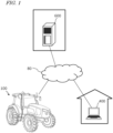
- FIG. 1 is a diagram providing an overview of an agriculture management system according to an illustrative embodiment of the present disclosure.
- the agriculture management system shown in FIG. 1 includes a work vehicle 100, a terminal device 400, and a management device 600.
- the terminal device 400 is a computer used by a user performing remote monitoring of the work vehicle 100.
- the management device 600 is a computer managed by a business operator running the agriculture management system.
- the work vehicle 100, the terminal device 400 and the management device 600 can communicate with each other via the network 80.
- FIG. 1 shows one work vehicle 100, but the agriculture management system may include a plurality of the work vehicles or any other agricultural machine.
- the work vehicle 100 is a tractor.
- the work vehicle 100 can have an implement attached to its rear and/or its front. While performing agricultural work in accordance with a particular type of implement, the work vehicle 100 is able to travel inside a field.
- the work vehicle 100 may travel inside the field or outside the field with no implement being attached thereto.
- the work vehicle 100 has a self-driving function. In other words, the work vehicle 100 can travel by the action of a controller, rather than manually.
- the controller according to the present embodiment is provided inside the work vehicle 100, and is able to control both the speed and steering of the work vehicle 100.
- the work vehicle 100 can perform self-traveling outside the field (e.g., on roads) as well as inside the field.
- the work vehicle 100 includes a device usable for positioning or localization, such as a GNSS receiver or a LiDAR sensor. Based on the position of the work vehicle 100 and information on a target path, the controller of the work vehicle 100 causes the work vehicle 100 to automatically travel. In addition to controlling the travel of the work vehicle 100, the controller also controls the operation of the implement. As a result, while automatically traveling inside the field, the work vehicle 100 is able to perform agricultural work by using the implement. In addition, the work vehicle 100 is able to automatically travel along the target path on a road outside the field (e.g., an agricultural road or a general road) . The work vehicle 100 automatically travels along the road outside the field by utilizing data that is output from a sensing device, such as a camera or a LiDAR sensor.
- a sensing device such as a camera or a LiDAR sensor.
- the management device 600 is a computer to manage the agricultural work performed by the work vehicle 100.
- the management device 600 may be, for example, a server computer that performs centralized management on information regarding the field on the cloud and supports agriculture by use of the data on the cloud.
- the management device 600 for example, creates a workplan for the work vehicle 100 and causes work vehicle 100 to perform agricultural work in accordance with the work plan.
- the management device 600 generates a target path inside the field based on, for example, information input by the user by use of the terminal device 400 or any other device.
- the management device 600 may generate or edit an environment map based on data collected by the work vehicle 100 or any other movable body by use of the sensing device such as a LiDAR sensor.
- the management device 600 transmits data on the work plan, the target path and the environment map thus generated to the work vehicle 100.
- the work vehicle 100 automatically moves and performs agricultural work based on the data.
- the terminal device 400 is a computer that is used by a user who is at a remote place from the work vehicle 100.
- the terminal device 400 shown in FIG. 1 is a laptop computer, but the terminal device 400 is not limited to this .
- the terminal device 400 may be a stationary computer such as a desktop PC (personal computer), or a mobile terminal such as a smartphone or a tablet computer.
- the terminal device 400 may be used to perform remote monitoring of the work vehicle 100 or remote-manipulate the work vehicle 100.
- the terminal device 400 can display, on a display screen thereof, a video captured by one or more cameras (imagers) included in the work vehicle 100.
- the terminal device 400 can also display, on the display screen thereof, a setting screen allowing the user to input information necessary to create a work plan (e.g., a schedule of each task of agricultural work) for the work vehicle 100.
- a work plan e.g., a schedule of each task of agricultural work
- the terminal device 400 transmits the input information to the management device 600.
- the management device 600 creates a work plan based on the information.
- the terminal device 400 may further have a function of displaying, on a display screen thereof, a setting screen allowing the user to input information necessary to set a target path.
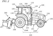
- FIG. 2 is a side view schematically showing an example of the work vehicle 100 and an example of implement 300 linked to the work vehicle 100.
- the work vehicle 100 according to the present embodiment can operate both in a manual driving mode and a self-driving mode. In the self-driving mode, the work vehicle 100 is able to perform unmanned travel. The work vehicle 100 can perform self-driving both inside a field and outside the field.
- the work vehicle 100 includes a vehicle body 101, a prime mover (engine) 102, and a transmission 103.
- wheels 104 with tires and a cabin 105 are provided on the vehicle body 101.
- the wheels 104 include a pair of front wheels 104F and a pair of rear wheels 104R.
- a driver's seat 107, a steering device 106, an operational terminal 200, and switches for manipulation are provided inside the cabin 105.
- the front wheels 104F and/or the rear wheels 104R may be replaced by a plurality of wheels (crawlers) to which a continuous track is attached, instead of tire-mounted wheels.
- the work vehicle 100 includes at least one sensing device sensing the surroundings of the work vehicle 100.
- the work vehicle 100 includes a plurality of sensing devices.
- the sensing devices include a plurality of cameras 120, a LiDAR sensor 140, and a plurality of obstacle sensors 130.
- the cameras 120 may be provided at the front/rear/right/left of the work vehicle 100, for example.
- the cameras 120 image the surrounding environment of the work vehicle 100 and generate image data.
- the images acquired with the cameras 120 may be transmitted to the terminal device 400, which is responsible for remote monitoring.
- the images may be used to monitor the work vehicle 100 during unmanned driving.
- the cameras 120 may also be used to generate images to allow the work vehicle 100, traveling on a road outside the field (an agricultural road or a general road), to recognize objects, obstacles, white lines, road signs, traffic signs or the like in the surroundings of the work vehicle 100.
- the LiDAR sensor 140 in the example shown in FIG. 2 is disposed on a bottom portion of a front surface of the vehicle body 101.
- the LiDAR sensor 140 may be disposed at any other position.
- the LiDAR sensor 140 may be disposed on the top portion of the cabin 105.
- the LiDAR sensor 140 may be a 3D-LiDAR sensor, but also a 2D-LiDAR sensor.
- the LiDAR sensor 140 senses the surrounding environment of the work vehicle 100 and outputs the sensing data. While the work vehicle 100 is traveling, the LiDAR sensor 140 repeatedly outputs sensor data representing the distance and the direction between an object existing in the surrounding environment thereof and each of measurement points, or a two-dimensional or three-dimensional coordinate values of each of the measurement points.
- the sensor data that is output from the LiDAR sensor 140 is processed by the controller of the work vehicle 100.
- the controller can perform localization of the work vehicle 100 by matching the sensor data against the environment map.
- the controller can further detect an object such as an obstacle existing in the surroundings of the work vehicle 100 based on the sensor data.
- the controller can utilize an algorithm such as, for example, SLAM (Simultaneous Localization and Mapping) to generate or edit an environment map.
- the work vehicle 100 may include a plurality of LiDAR sensors disposed at different positions with different orientations.
- the plurality of obstacle sensors 130 shown in FIG. 2 are provided at the front and the rear of the cabin 105.
- the obstacle sensors 130 may be disposed at other positions.
- one or more obstacle sensors 130 may be disposed at any position at the sides, the front or the rear of the vehicle body 101.
- the obstacle sensors 130 may include, for example, a laser scanner or an ultrasonic sonar.
- the obstacle sensors 130 may be used to detect obstacles in the surroundings of the work vehicle 100 during self-traveling to cause the work vehicle 100 to halt or detour around the obstacles.
- the LiDAR sensor 140 may be used as one of the obstacle sensors 130. Further, as described later, the LiDAR sensor 140 and the cameras 120 may be used in cooperation as sensors to detect the obstacle.
- the work vehicle 100 further includes a GNSS unit 110.
- the GNSS unit 110 includes a GNSS receiver.
- the GNSS receiver may include an antenna to receive a signal (s) from a GNSS satellite(s) and a processor to calculate the position of the work vehicle 100 based on the signal(s) received by the antenna.
- the GNSS unit 110 receives satellite signals transmitted from the plurality of GNSS satellites, and performs positioning based on the satellite signals.
- GNSS is the general term for satellite positioning systems such as GPS (Global Positioning System), QZSS (Quasi-Zenith Satellite System; e.g., MICHIBIKI), GLONASS, Galileo, and BeiDou.
- GPS Global Positioning System
- QZSS Quadasi-Zenith Satellite System
- GLONASS Galileo
- BeiDou BeiDou.
- the GNSS unit 110 may include an inertial measurement unit (IMU) . Signals from the IMU can be used to complement position data.
- the IMU can measure a tilt or a small motion of the work vehicle 100.
- the data acquired by the IMU can be used to complement the position data based on the satellite signals, so as to improve the performance of positioning.
- the controller of the work vehicle 100 may utilize, for positioning, the sensing data acquired with the sensing devices such as the cameras 120 or the LIDAR sensor 140, in addition to the positioning results provided by the GNSS unit 110.
- the position and the orientation of the work vehicle 100 can be estimated with a high accuracy based on data that is acquired by the cameras 120 or the LiDAR sensor 140 and on an environment map that is previously stored in the storage device.
- By correcting or complementing position data based on the satellite signals using the data acquired with the cameras 120 or the LiDAR sensor 140 it becomes possible to identify the position of the work vehicle 100 with a higher accuracy.
- the work vehicle 100 further includes one or more lighting devices 230.
- lighting devices 230 In FIG. 2 , only one lighting device 230 is exemplified, however, various lighting devices 230 such as headlights, work lights, and clearance lights may be provided at a plurality of positions of the work vehicle 100. These lighting devices 230 are controlled by the controller.
- the prime mover 102 may be a diesel engine, for example. Instead of a diesel engine, an electric motor may be used.
- the transmission 103 can change the propulsion and the moving speed of the work vehicle 100 through a speed changing mechanism.
- the transmission 103 can also switch between forward travel and backward travel of the work vehicle 100.
- the steering device 106 includes a steering wheel, a steering shaft connected to the steering wheel, and a power steering device to assist in the steering by the steering wheel.
- the front wheels 104F are the steered wheels, such that changing their angle of turn (also referred to as "steering angle") can cause a change in the traveling direction of the work vehicle 100.
- the steering angle of the front wheels 104F can be changed by manipulating the steering wheel.
- the power steering device includes a hydraulic device or an electric motor to supply an assisting force to change the steering angle of the front wheels 104F.
- the steering angle may be automatically adjusted by the power of the hydraulic device or the electric motor.
- a linkage device 108 is provided at the rear of the vehicle body 101.
- the linkage device 108 includes, e.g., a three-point linkage (also referred to as a "three-point link” or a "three-point hitch"), a PTO (Power Take Off) shaft, a universal joint, and a communication cable.
- the linkage device 108 allows the implement 300 to be attached to, or detached from, the work vehicle 100.
- the linkage device 108 is able to raise or lower the three-point link with a hydraulic device, for example, thus changing the position and/or attitude of the implement 300.
- motive power can be sent from the work vehicle 100 to the implement 300 via the universal joint. While towing the implement 300, the work vehicle 100 allows the implement 300 to perform a predetermined task.
- the linkage device may be provided at the front of the vehicle body 101. In that case, the implement can be connected at the front of the work vehicle 100.
- the implement 300 shown in FIG. 2 is a rotary tiller
- the implement 300 is not limited to a rotary tiller.
- any arbitrary implement such as a seeder, a spreader, a transplanter, a mower, a rake implement, a baler, a harvester, a sprayer, or a harrow, can be connected to the work vehicle 100 for use.
- the work vehicle 100 shown in FIG. 2 can be driven by human driving; alternatively, it may only support unmanned driving. In that case, component elements which are only required for human driving, e.g., the cabin 105, the steering device 106, and the driver's seat 107 do not need to be provided in the work vehicle 100.
- An unmanned work vehicle 100 can travel via autonomous driving, or by remote operation by a user.
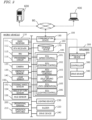
- FIG. 3 is a block diagram showing an example configuration of the work vehicle 100 and the implement 300.
- the work vehicle 100 and the implement 300 can communicate with each other via a communication cable that is included in the linkage device 108.
- the work vehicle 100 is able to communicate with the terminal device 400 and the management device 600 via the network 80.
- the work vehicle 100 in the example of FIG. 3 includes sensors 150 to detect the operating status of the work vehicle 100, a control system 160, a communication device 190, operation switches 210, a buzzer 220, and a drive device 240. These component elements are communicably connected to each other via a bus.
- the GNSS unit 110 includes a GNSS receiver 111, an RTK receiver 112, an inertial measurement unit (IMU) 115, and a processing circuit 116.
- the sensors 150 include a steering wheel sensor 152, an angle-of-turn sensor 154, and an axle sensor 156.
- the control system 160 includes a storage device 170 and a controller 180.
- the controller 180 includes a plurality of electronic control units (ECU) 181 to 186.
- the implement 300 includes a drive device 340, a controller 380, and a communication device 390. Note that FIG. 3 shows component elements which are relatively closely related to the operations of self-driving by the work vehicle 100, while other components are omitted from illustration.
- the GNSS receiver 111 in the GNSS unit 110 receives satellite signals transmitted from the plurality of GNSS satellites and generates GNSS data based on the satellite signals.
- the GNSS data is generated in a predetermined format such as, for example, the NMEA-0183 format.
- the GNSS data may include, for example, the identification number, the angle of elevation, the azimuth angle, and a value representing the reception strength of each of the satellites from which the satellite signals are received.
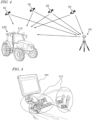
- the GNSS unit 110 shown in FIG. 3 performs positioning of the work vehicle 100 by utilizing an RTK (Real Time Kinematic) -GNSS.
- FIG. 4 is a conceptual diagram showing an example of the work vehicle 100 performing positioning based on the RTK-GNSS.
- the reference station 60 may be disposed near the field where the work vehicle 100 performs tasked travel (e.g., at a position within 10 km of the work vehicle 100).
- the reference station 60 generates a correction signal of, for example, an RTCM format based on the satellite signals received from the plurality of GNSS satellites 50, and transmits the correction signal to the GNSS unit 110.
- the RTK receiver 112 which includes an antenna and a modem, receives the correction signal transmitted from the reference station 60. Based on the correction signal, the processing circuit 116 of the GNSS unit 110 corrects the results of the positioning performed by use of the GNSS receiver 111.
- Use of the RTK-GNSS enables positioning with an accuracy on the order of several centimeters of errors, for example. Positional information including latitude, longitude, and altitude information is acquired through the highly accurate positioning by the RTK-GNSS.
- the GNSS unit 110 calculates the position of the work vehicle 100 as frequently as, for example, one to ten times per second.
- the positioning method is not limited to being performed by use of an RTK-GNSS; any arbitrary positioning method (e.g., an interferometric positioning method or a relative positioning method) that provides positional information with the necessary accuracy can be used.
- positioning may be performed by utilizing a VRS (Virtual Reference Station) or a DGPS (Differential Global Positioning System).
- VRS Virtual Reference Station
- DGPS Different Global Positioning System
- positional information with the necessary accuracy can be obtained without the use of the correction signal transmitted from the reference station 60
- positional information may be generated without using the correction signal.
- the GNSS unit 110 does not need to include the RTK receiver 112.
- the position of the work vehicle 100 is estimated by another method with no use of the signal from the RTK receiver 112.
- the position of the work vehicle 100 may be estimated by matching the data that is output from the LiDAR sensor 140 and/or the cameras 120 against a highly accurate environment map.
- the GNSS unit 110 further includes the IMU 115.
- the IMU 115 may include a 3-axis accelerometer and a 3-axis gyroscope.
- the IMU 115 may include a direction sensor such as a 3 -axis geomagnetic sensor.
- the IMU 115 functions as a motion sensor which can output signals representing parameters such as acceleration, velocity, displacement, and attitude of the work vehicle 100.
- the processing circuit 116 can estimate the position and orientation of the work vehicle 100 with a higher accuracy.
- the signal that is output from the IMU 115 may be used for the correction or complementation of the position that is calculated based on the satellite signals and the correction signal.
- the IMU 115 outputs a signal more frequently than the GNSS receiver 111. Utilizing this signal that is output highly frequently, the processing circuit 116 allows the position and orientation of the work vehicle 100 to be measured more frequently (e.g., about 10 Hz or above) .
- the processing circuit 116 allows the position and orientation of the work vehicle 100 to be measured more frequently (e.g., about 10 Hz or above) .
- a 3-axis accelerometer and a 3-axis gyroscope may be separately provided.
- the IMU 115 may be provided as a separate device from the GNSS unit 110.
- the cameras 120 are imagers that image the surrounding environment of the work vehicle 100.
- Each of the cameras 120 includes an image sensor such as a CCD (Charge Coupled Device) or a CMOS (Complementary Metal Oxide Semiconductor), for example.
- each camera 120 may include an optical system including one or more lenses and a signal processing circuit.
- the cameras 120 image the surrounding environment of the work vehicle 100, and generate image data (e.g., motion picture data).
- the cameras 120 are able to capture motion pictures at a frame rate of 3 frames/second (fps: frames per second) or greater, for example.
- the images generated by the cameras 120 may be used by a remote supervisor to check the surrounding environment of the work vehicle 100 with the terminal device 400, for example.
- the images generated by the cameras 120 may also be used for the purpose of positioning and/or detection of obstacles.
- the plurality of cameras 120 may be provided at different positions on the work vehicle 100, or a single camera 120 may be provided.
- a visible camera(s) to generate visible light images and an infrared camera(s) to generate infrared images may be separately provided. Both of a visible camera(s) and an infrared camera(s) may be provided as cameras for generating images for monitoring purposes.
- the infrared camera(s) may also be used for detection of obstacles at nighttime.
- the obstacle sensors 130 detect objects existing in the surroundings of the work vehicle 100.
- Each of the obstacle sensors 130 may include a laser scanner or an ultrasonic sonar, for example.
- the obstacle sensor 130 When an object exists at a position within a predetermined distance from one of the obstacle sensors 130, the obstacle sensor 130 outputs a signal indicating the presence of the obstacle.
- the plurality of obstacle sensors 130 may be provided at different positions on the work vehicle 100.
- a plurality of laser scanners and a plurality of ultrasonic sonars may be disposed at different positions on the work vehicle 100. Providing such a great number of obstacle sensors 130 can reduce blind spots in monitoring obstacles in the surroundings of the work vehicle 100.
- the steering wheel sensor 152 measures the angle of rotation of the steering wheel of the work vehicle 100.
- the angle-of -turn sensor 154 measures the angle of turn of the front wheels 104F, which are the steered wheels . Measurement values by the steering wheel sensor 152 and the angle-of-turn sensor 154 are used for steering control by the controller 180.
- the axle sensor 156 measures the rotational speed, i.e., the number of revolutions per unit time, of an axle that is connected to the wheels 104.
- the axle sensor 156 may be a sensor including a magnetoresistive element (MR), a Hall generator, or an electromagnetic pickup, for example.
- the axle sensor 156 outputs a numerical value indicating the number of revolutions per minute (unit: rpm) of the axle, for example.
- the axle sensor 156 is used to measure the speed of the work vehicle 100.
- the drive device 240 includes various types of devices required to cause the work vehicle 100 to travel and to drive the implement 300; for example, the prime mover 102, the transmission 103, the steering device 106, the linkage device 108 and the like described above.
- the prime mover 102 may include an internal combustion engine such as, for example, a diesel engine.
- the drive device 240 may include an electric motor for traction instead of, or in addition to, the internal combustion engine.
- the buzzer 220 is an audio output device to present an alarm sound to alert the user of an abnormality.
- the buzzer 220 may present an alarm sound when an obstacle is detected during self-driving.
- the buzzer 220 is controlled by the controller 180.
- the storage device 170 includes one or more storage mediums such as a flash memory or a magnetic disc.
- the storage device 170 stores various data that is generated by the GNSS unit 110, the cameras 120, the obstacle sensors 130, the LiDAR sensor 140, the sensors 150, and the controller 180.
- the data that is stored by the storage device 170 may include map data on the environment where the work vehicle 100 travels (environment map) and data on a target path for self-driving.
- the environment map includes information on a plurality of fields where the work vehicle 100 performs agricultural work and roads around the fields.
- the environment map and the target path may be generated by a processor in the management device 600.
- the controller 180 may have a function of generating or editing an environment map and a target path.
- the controller 180 can edit the environment map and the target path, acquired from the management device 160, in accordance with the environment where the work vehicle 100 travels.
- the storage device 170 also stores data on a work plan received by the communication device 190 from the management device 600.
- the work plan includes information on a plurality of tasks of agricultural work to be performed by the work vehicle 100 over a plurality of working days.
- the storage device 170 also stores a computer program(s) to cause each of the ECUs in the controller 180 to perform various operations described below.
- a computer program(s) may be provided to the work vehicle 100 via a storage medium (e.g., a semiconductor memory, an optical disc, etc.) or through telecommunication lines (e.g., the Internet) .
- a storage medium e.g., a semiconductor memory, an optical disc, etc.
- telecommunication lines e.g., the Internet
- Such a computer program(s) may be marketed as commercial software.
- the controller 180 includes the plurality of ECUs.
- the plurality of ECUs include, for example, the ECU 181 for speed control, the ECU 182 for steering control, the ECU 183 for implement control, the ECU 184 for self-driving control, the ECU 185 for path generation, and the ECU 186 for lighting control.
- the ECU 181 controls the prime mover 102, the transmission 103 and brakes included in the drive device 240, thus controlling the speed of the work vehicle 100.
- the ECU 182 controls the hydraulic device or the electric motor included in the steering device 106 based on a measurement value of the steering wheel sensor 152, thus controlling the steering of the work vehicle 100.
- the ECU 183 controls the operations of the three-point link, the PTO shaft and the like that are included in the linkage device 108. Also, the ECU 183 generates a signal to control the operation of the implement 300, and transmits this signal from the communication device 190 to the implement 300.
- the ECU 184 Based on data output from the GNSS unit 110, the cameras 120, the obstacle sensors 130, the LiDAR sensor 140 and the sensors 150, the ECU 184 performs computation and control for achieving self-driving. For example, the ECU 184 specifies the position of the work vehicle 100 based on the data output from at least one of the GNSS unit 110, the cameras 120 and the LiDAR sensor 140. Inside the field, the ECU 184 may determine the position of the work vehicle 100 based only on the data output from the GNSS unit 110. The ECU 184 may estimate or correct the position of the work vehicle 100 based on the data acquired with the cameras 120 or the LiDAR sensor 140. Use of the data acquired with the cameras 120 or the LiDAR sensor 140 allows the accuracy of the positioning to be further improved.
- the ECU 184 estimates the position of the work vehicle 100 by use of the data output from the LiDAR sensor 140 or the cameras 120. For example, the ECU 184 may estimate the position of the work vehicle 100 by matching the data output from the LiDAR sensor 140 or the cameras 120 against the environment map. During self-driving, the ECU 184 performs computation necessary for the work vehicle 100 to travel along a target path, based on the estimated position of the work vehicle 100. The ECU 184 sends the ECU 181 a command to change the speed, and sends the ECU 182 a command to change the steering angle.
- the ECU 181 controls the prime mover 102, the transmission 103 or the brakes to change the speed of the work vehicle 100.
- the ECU 182 controls the steering device 106 to change the steering angle.
- the ECU 185 recognizes an obstacle existing in the surroundings of the work vehicle 100 based on the data output from the cameras 120, the obstacle sensors 130 and the LiDAR sensor 140.
- the ECU 185 may also determine a destination of the work vehicle 100 based on the work plan stored in the storage device 170, and determine a target path from a beginning point to a target point of the movement of the work vehicle 100.
- the ECU 186 controls the illumination and extinction of each lighting device 230.
- ECU 186 may be configured to adjust the light output (e.g., luminous intensity) of each lighting device 230.
- the ECU 186 may adjust the light output of the lighting device 230 by changing the driving voltage or driving current that is input to the lighting device 230.
- the controller 180 realizes self-driving.
- the controller 180 controls the drive device 240 based on the measured or estimated position of the work vehicle 100 and on the target path. As a result, the controller 180 can cause the work vehicle 100 to travel along the target path.
- the plurality of ECUs included in the controller 180 can communicate with each other in accordance with a vehicle bus standard such as, for example, a CAN (Controller Area Network). Instead of the CAN, faster communication methods such as Automotive Ethernet (registered trademark) may be used.
- a vehicle bus standard such as, for example, a CAN (Controller Area Network).
- CAN Controller Area Network
- faster communication methods such as Automotive Ethernet (registered trademark) may be used.
- the ECUs 181 to 186 are illustrated as individual blocks in FIG. 3 , the function of each of the ECU 181 to 186 may be implemented by a plurality of ECUs. Alternatively, an onboard computer that integrates the functions of at least some of the ECUs 181 to 186 may be provided.
- the controller 180 may include ECUs other than the ECUs 181 to 186, and any number of ECUs may be provided in accordance with functionality.
- Each ECU includes a processing circuit including one or more processors.
- the communication device 190 is a device including a circuit communicating with the implement 300, the terminal device 400 and the management device 600.
- the communication device 190 includes circuitry to perform exchanges of signals complying with an ISOBUS standard such as ISOBUS-TIM, for example, between itself and the communication device 390 of the implement 300. This allows the implement 300 to perform a desired operation, or allows information to be acquired from the implement 300.
- the communication device 190 may further include an antenna and a communication circuit to exchange signals via the network 80 with communication devices of the terminal device 400 and the management device 600.
- the network 80 may include a 3G, 4G, 5G, or any other cellular mobile communications network and the Internet, for example.
- the communication device 190 may have a function of communicating with a mobile terminal that is used by a supervisor who is situated near the work vehicle 100. With such a mobile terminal, communication may be performed based on any arbitrary wireless communication standard, e.g., Wi-Fi (registered trademark), 3G, 4G, 5G or any other cellular mobile communication standard, or Bluetooth (registered trademark).
- Wi-Fi registered trademark
- 3G, 4G, 5G any other cellular mobile communication standard
- Bluetooth registered trademark
- the operational terminal 200 is a terminal for the user to perform a manipulation related to the travel of the work vehicle 100 and the operation of the implement 300, and is also referred to as a virtual terminal (VT).
- the operational terminal 200 may include a display device such as a touch screen panel, and/or one or more buttons.
- the display device may be a display such as a liquid crystal display or an organic light-emitting diode (OLED) display, for example.
- OLED organic light-emitting diode
- the operational terminal 200 may be configured so as to be detachable from the work vehicle 100.
- a user who is at a remote place from the work vehicle 100 may manipulate the detached operational terminal 200 to control the operation of the work vehicle 100.
- the user may manipulate a computer on which necessary application software is installed, for example, the terminal device 400, to control the operation of the work vehicle 100.
- FIG. 5 is a diagram showing an example of the operational terminal 200 and an example of the operation switches 210 both provided in the cabin 105.
- the operation switches 210 including a plurality of switches that are manipulable to the user, are disposed.
- the operation switches 210 may include, for example, a switch to select the gear shift as to a main gear shift or a range gear shift, a switch to switch between a self-driving mode and a manual driving mode, a switch to switch between forward travel and backward travel, a switch to raise or lower the implement 300, and the like.
- the work vehicle 100 does not need to include the operation switches 210.
- the drive device 340 in the implement 300 shown in FIG. 3 performs operations necessary for the implement 300 to perform predetermined work.
- the drive device 340 includes a device suitable for uses of the implement 300, for example, a hydraulic device, an electric motor, a pump or the like.
- the controller 380 controls the operation of the drive device 340.
- the controller 380 causes the drive device 340 to perform various operations .
- a signal that is in accordance with the state of the implement 300 can be transmitted from the communication device 390 to the work vehicle 100.
- FIG. 6 is a block diagram showing an example of schematic hardware configuration of the management device 600 and the terminal device 400.
- the management device 600 includes a storage device 650, a processor 660, a ROM (Read Only Memory) 670, a RAM (Random Access Memory) 680, and a communication device 690. These component elements are communicably connected to each other via a bus.
- the management device 600 may function as a cloud server to manage the schedule of the agricultural work to be performed by the work vehicle 100 in a field and support agriculture by use of the data managed by the management device 600 itself.
- the user can input information necessary to create a work plan by use of the terminal device 400 and upload the information to the management device 600 via the network 80.
- the management device 600 can create a schedule of agricultural work, that is, a work plan based on the information.
- the management device 600 can further generate or edit an environment map.
- the environment map may be distributed from a computer external to the management device 600.
- the communication device 690 is a communication module to communicate with the work vehicle 100 and the terminal device 400 via the network 80.
- the communication device 690 can perform wired communication in compliance with communication standards such as, for example, IEEE1394 (registered trademark) or Ethernet (registered trademark).
- the communication device 690 may perform wireless communication in compliance with Bluetooth (registered trademark) or Wi-Fi, or cellular mobile communication based on 3G, 4G, 5G or any other cellular mobile communication standard.
- the processor 660 may be, for example, a semiconductor integrated circuit including a central processing unit (CPU) .
- the processor 660 may be realized by a microprocessor or a microcontroller.
- the processor 660 may be realized by an FPGA (Field Programmable Gate Array), a GPU (Graphics Processing Unit), an ASIC (Application Specific Integrated Circuit) or an ASSP (Application Specific Standard Product) each including a CPU, or a combination of two or more selected from these circuits.
- the processor 660 consecutively executes a computer program, describing commands to execute at least one process, stored in the ROM 670 and thus realizes a desired process.
- the ROM 670 is, for example, a writable memory (e.g., PROM), a rewritable memory (e.g., flash memory) or a memory which can only be read from but cannot be written to.
- the ROM 670 stores a program to control operations of the processor 660.
- the ROM 670 does not need to be a single storage medium, and may be an assembly of a plurality of storage mediums. A portion of the assembly of the plurality of storage memories may be a detachable memory.
- the RAM 680 provides a work area in which the control program stored in the ROM 670 is once developed at the time of boot.
- the RAM 680 does not need to be a single storage medium, and may be an assembly of a plurality of storage mediums.
- the storage device 650 mainly functions as a storage for a database.
- the storage device 650 may be, for example, a magnetic storage device or a semiconductor storage device.
- An example of the magnetic storage device is a hard disc drive (HDD).
- An example of the semiconductor storage device is a solid state drive (SSD) .
- the storage device 650 may be a device independent from the management device 600.
- the storage device 650 may be a storage device connected to the management device 600 via the network 80, for example, a cloud storage.
- the terminal device 400 includes an input device 420, a display device 430, a storage device 450, a processor 460, a ROM 470, a RAM 480, and a communication device 490. These component elements are communicably connected to each other via a bus.
- the input device 420 is a device to convert an instruction from the user into data and input the data to a computer.
- the input device 420 may be, for example, a keyboard, a mouse or a touch panel.
- the display device 430 may be, for example, a liquid crystal display or an organic EL display.
- the processor 460, the ROM 470, the RAM 480, the storage device 450 and the communication device 490 are substantially the same as the corresponding component elements described above regarding the example of the hardware configuration of the management device 600, and will not be described in repetition.
- the work vehicle 100 can automatically travel both inside and outside a field.
- the work vehicle 100 drives the implement 300 to perform predetermined agricultural work while traveling along a preset target path.
- the work vehicle 100 may halt traveling and perform operations of presenting an alarm sound from the buzzer 220, transmitting an alert signal to the terminal device 400 and the like.
- the positioning of the work vehicle 100 is performed based mainly on data output from the GNSS unit 110.
- the work vehicle 100 automatically travels along a target path set for an agricultural road or a general road outside the field. While traveling outside the field, the work vehicle 100 utilizes the data acquired by the cameras 120 or the LiDAR 140. When an obstacle is detected outside the field, the work vehicle 100, for example, avoids the obstacle or halts at the point. Outside the field, the position of the work vehicle 100 can be estimated based on data output from the LiDAR sensor 140 or the cameras 120 in addition to positioning data output from the GNSS unit 110.
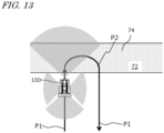
- FIG. 7 is a diagram schematically showing an example of the work vehicle 100 automatically traveling along a target path in a field.
- the field includes a work area 72, in which the work vehicle 100 performs work by using the implement 300, and headlands 74, which are located near outer edges of the field. The user may previously specify which regions of the field on the map would correspond to the work area 72 and the headlands 74.
- the target path in this example includes a plurality of main paths P1 parallel to each other and a plurality of turning paths P2 interconnecting the plurality of main paths P1.
- the main paths P1 are located in the work area 72, whereas the turning paths P2 are located in the headlands 74.
- each main path P1 may also include a curved portion (s) .
- Broken lines in FIG. 7 depict the working breadth of the implement 300.
- the working breadth is previously set and recorded in the storage device 170.
- the working breadth may be set and recorded by the user manipulating the operational terminal 200 or the terminal device 400. Alternatively, the working breadth may be automatically recognized and recorded when the implement 300 is connected to the work vehicle 100.
- the interval between the plurality of main paths P1 may be set so as to be matched to the working breadth.
- the target path may be generated based on the manipulation made by the user, before self-driving is begun.
- the target path may be generated so as to cover the entire work area 72 in the field, for example.
- the work vehicle 100 automatically travels while repeating a reciprocating motion from a beginning point of work to an ending point of work. Note that the target path shown in FIG. 7 is merely an example, and the target path may be arbitrarily determined.
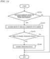
- FIG. 8 is a flowchart showing an example operation of steering control to be performed by the controller 180 during self -driving.
- the controller 180 performs automatic steering by performing the operation from steps S121 to S125 shown in FIG. 8 .
- the speed of the work vehicle 100 will be maintained at a previously-set speed, for example.
- the controller 180 acquires data representing the position of the work vehicle 100 that is generated by the GNSS unit 110 (step S121).
- the controller 180 calculates a deviation between the position of the work vehicle 100 and the target path (step S122) .
- the deviation represents the distance between the position of the work vehicle 100 and the target path at that moment.
- the controller 180 determines whether the calculated deviation in position exceeds the previously-set threshold or not (step S123). If the deviation exceeds the threshold, the controller 180 changes a control parameter of the steering device included in the drive device 240 so as to reduce the deviation, thus changing the steering angle (step S124) . If the deviation does not exceed the threshold at step S123, the operation of step S124 is omitted. At the following step S125, the controller 180 determines whether a command to end the operation has been received or not. The command to end the operation may be given when the user has instructed that self-driving be suspended through remote operations, or when the work vehicle 100 has arrived at the destination, for example.
- step S121 the control returns to step S121 and the controller 180 performs substantially the same operation based on a newly measured position of the work vehicle 100.
- the controller 180 repeats the operation from steps S121 to S125 until a command to end the operation is given.
- the aforementioned operation is executed by the ECUs 182 and 184 in the controller 180.
- the controller 180 controls the drive device 240 based only on the deviation between the position of the work vehicle 100 as identified by the GNSS unit 110 and the target path.
- a deviation in terms of directions may further be considered in the control.
- the controller 180 may change the control parameter of the steering device of the drive device 240 (e.g., steering angle) in accordance with the deviation.
- FIG. 9A is a diagram showing an example of the work vehicle 100 traveling along a target path P.
- FIG. 9B is a diagram showing an example of the work vehicle 100 at a position which is shifted rightward from the target path P.
- FIG. 9C is a diagram showing an example of the work vehicle 100 at a position which is shifted leftward from the target path P.
- FIG. 9D is a diagram showing an example of the work vehicle 100 oriented in an inclined direction with respect to the target path P.
- the pose, i.e., the position and orientation, of the work vehicle 100 as measured by the GNSS unit 110 is expressed as r(x,y, ⁇ ).
- (x,y) are coordinates representing the position of a reference point on the work vehicle 100 in an XY coordinate system, which is a two-dimensional coordinate system fixed to the globe.
- the reference point on the work vehicle 100 is at a position, on the cabin, where a GNSS antenna is disposed, but the reference point may be at any arbitrary position.
- ⁇ is an angle representing the measured orientation of the work vehicle 100.
- the target path P is shown parallel to the Y axis in the examples illustrated in these figures, the target path P may not necessarily be parallel to the Y axis, in general.
- the controller 180 maintains the steering angle and speed of the work vehicle 100 without changing them.
- the controller 180 changes the steering angle so that the traveling direction of the work vehicle 100 will be inclined leftward, thus bringing the work vehicle 100 closer to the path P.
- the controller 180 changes the steering angle so that the traveling direction of the work vehicle 100 will be inclined leftward, thus bringing the work vehicle 100 closer to the path P.
- the magnitude of the steering angle may be adjusted in accordance with the magnitude of a positional deviation ⁇ x, for example.
- the controller 180 changes the steering angle so that the traveling direction of the work vehicle 100 will be inclined rightward, thus bringing the work vehicle 100 closer to the path P.
- the steering angle may be adjusted in accordance with the magnitude of the positional deviation ⁇ x, for example.
- the controller 180 changes the steering angle so that the directional deviation ⁇ will become smaller.
- the magnitude of the steering angle may be adjusted in accordance with the magnitudes of the positional deviation ⁇ x and the directional deviation ⁇ , for example. For instance, the amount of change of the steering angle (which is in accordance with the directional deviation ⁇ ) may be increased as the absolute value of the positional deviation ⁇ x decreases.
- the steering angle will be changed greatly in order for the work vehicle 100 to return to the path P, so that the directional deviation ⁇ will inevitably have a large absolute value.
- the directional deviation ⁇ needs to become closer to zero. Therefore, it may be advantageous to introduce a relatively large weight (i.e., control gain) for the directional deviation ⁇ in determining the steering angle.
- control techniques such as PID control or MPC (Model Predictive Control) may be applied. Applying these control techniques will make for smoothness of the control of bringing the work vehicle 100 closer to the target path P.
- the controller 180 when an obstacle is detected by one or more obstacle sensors 130 (or based on data that is output from the LiDAR sensor 140 and the cameras 120) during travel, the controller 180, for example, halts the work vehicle 100. At this point, the controller 180 may cause the buzzer 220 to present an alarm sound or may transmit an alert signal to the terminal device 400. In the case where the obstacle is avoidable, the controller 180 may generate a local path that allows for avoiding the obstacle and control the drive device 240 such that the work vehicle 100 travels along the path.
- the work vehicle 100 can perform self-traveling outside a field as well as inside the field.
- the controller 180 is able to detect an object located at a relatively distant position from the work vehicle 100 (e.g., another vehicle, a pedestrian, etc.) based on data output from the cameras 120 or the LiDAR sensor 140.
- the controller 180 performs speed control and steering control to avoid the detected obstacle. In this manner, self - traveling on a road outside the field can be realized.
- FIG. 10 is a diagram schematically showing an example of state where a plurality of the work vehicles 100 are performing self-traveling inside a field 70 and on a road 76 outside the field 70.
- an environment map of a region including a plurality of fields and roads around the fields, and a target path are recorded.
- the environment map and the target path may be generated by the management device 600 or the ECU 185.
- the work vehicle 100 travels along the target path while sensing the surroundings thereof by use of the sensing devices such as the cameras 120 and the LiDAR sensor 140, with the implement 300 being raised.
- the controller 180 of the work vehicle 100 functions as an obstacle detection system for the work vehicle 100 in cooperation with a LiDAR sensor(s) 140 and a camera(s) 120.
- the work vehicle 100 performs self-driving while sensing the surrounding environment with a LiDAR sensor(s) 140 and a camera(s) 120.
- the work vehicle 100 has one or more LiDAR sensors 140 and one or more cameras 120, and performs self-driving while sensing the surrounding environment with at least one LiDAR sensor 140 and at least one camera 120 among them.
- a candidate of an obstacle hereinafter, "obstacle candidate"
- the controller 180 Upon detecting, as a trigger, a candidate of an obstacle (hereinafter, "obstacle candidate") based on data that is output (e.g., point cloud data) from the LiDAR sensor(s) 140, the controller 180 causes the camera (s) 120 to acquire an image (e.g., a color image) of the obstacle candidate.
- the controller 180 further determines whether or not to change the traveling status of the work vehicle 100 based on the image of the obstacle candidate acquired with the camera(s) 120.
- the "traveling status" of the work vehicle 100 is defined by parameters such as the speed, acceleration, and traveling direction of the work vehicle 100.
- the parameters determining the "traveling status" of the work vehicle 100 may include the target path of the work vehicle 100, and may include positional and directional information of each of a plurality of waypoints defining the target path.
- Changing the traveling status of the work vehicle 100 refers to changing at least one of the parameters defining the traveling status of the work vehicle 100. Changing the traveling status of the work vehicle 100 includes, for example, decelerating the work vehicle 100, halting the travel of the work vehicle 100, and changing the target path of the work vehicle 100.
- Changing the traveling status of the work vehicle 100 is not limited to changing the current state of the work vehicle 100 (e.g., speed, acceleration, traveling direction, etc.), but also includes changing the future state of the work vehicle 100 (e.g., speed, acceleration, traveling direction, etc.) by changing the target path of the work vehicle 100 although the current state of the work vehicle 100 remains unchanged.
- An "obstacle” is a subject with respect to which the traveling status of the work vehicle 100 should be changed, for instance, in order to avoid contact (including collision) with or approach to it.
- the subject that can be an obstacle is not limited to objects (including land objects, persons, animals, etc.), but can also include concavities or convexities formed on the ground surface.
- the obstacle also includes a stationary obstacle and a movable obstacle.
- the controller 180 detects any subject that can be an obstacle for the work vehicle 100 as an "obstacle candidate" based on data output from the LiDAR sensor(s) 140 within the range sensed by the LiDAR sensor(s) 140.
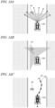
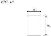
- the criteria for the controller 180 to detect obstacle candidates can be set in advance. For example, as shown in FIG.
- the controller 180 refers to the size (height H1, width W1) of an object (a detected object) sensed by the LiDAR sensor (s) 140, and if the size (height H1, width W1) of the detected object is larger than or equal to the decision value, the controller 180 detects the object as the obstacle candidate. For example, the controller 180 can set the largest value of height of the detected object as the height H1 and the largest value of width of the detected object as the width W1.
- the decision value can be set only for either the object height or width, or for both the object height and width.
- the decision value for example, is predetermined and stored in the storage device 170 of the work vehicle 100. The decision value can be set by the user operating the operational terminal 200 and the terminal device 400 and stored.
- the decision value can vary depending on the distance from the LiDAR sensor(s) 140 to the detected object.
- the controller 180 sets a smaller decision value as the distance from the LiDAR sensor(s) 140 to the detected object increases, and a larger decision value as the distance from the LiDAR sensor(s) 140 to the detected object decreases. Therefore, the shorter the distance from the LiDAR sensor(s) 140 to the detected object is, the larger objects are detected as obstacle candidates; and the longer the distance from the LiDAR sensor(s) 140 to the detected object is, the smaller objects are detected as obstacle candidates.
- the decision value can vary depending on the range sensed by the LiDAR sensor (s) 140. For example, as in the example of FIG.
- the controller 180 may set differing decision values for the range sensed by the LiDAR sensor 140a, which senses the front of the work vehicle 100, and for the range sensed by the LiDAR sensor 140b, which senses the rear of the work vehicle 100.
- the decision value for the range sensed by the LiDAR sensor 140a, which senses the front of the work vehicle 100 can be set smaller than the decision value for the range sensed by the LiDAR sensor 140b, which senses the rear of the work vehicle 100.
- the controller 180 may detect any objects within the range sensed by the LiDAR sensor(s) 140, excluding the ground surface, as obstacle candidates. Alternatively, the controller 180 may detect any objects within the range sensed by the LiDAR sensor (s) 140, further excluding any objects recorded on the environment map (objects such as buildings), as obstacle candidates. The controller 180 may detect any objects that are within or near the range which the work vehicle 100 occupies while the work vehicle 100 travels along the target path as obstacle candidates.
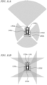
- FIGS. 11A and 11B schematically illustrate examples of the regions in which the LiDAR sensors 140 and the cameras 120 of the work vehicle 100 can sense.
- the work vehicle 100 includes four LiDAR sensors 140 (140a, 140b, 140c, and 140d) and four cameras 120 (120a, 120b, 120c, and 120d) that are provided at the front, the rear, the left side, and the right side of the work vehicle 100, and may sense the surrounding environment with them.
- examples of the ranges sensed by the LiDAR sensors 140 and the cameras 120 are shown as gray fans and triangles.
- the LiDAR sensor(s) 140 emits pulses of laser beams (hereinafter abbreviated as "laser pulses”) one after another while changing the emission direction, and is able to measure a distance to the position of each reflection point based on a time difference between the time of emission and the time when the reflected light of each laser pulse is received (ToF (Time of Flight) method) .
- the LiDAR sensor(s) 140 may be a sensor(s) using Frequency Modulated Continuous Wave (FMCW) technology to perform ranging.
- FMCW Frequency Modulated Continuous Wave
- a LiDAR sensor(s) using FMCW technology emits laser light that is linearly modulated in frequency, and is able to calculate a distance to the reflection point and velocity based on the frequency of a beat signal acquired by sensing coherent light between the emitted light and the reflected light.
- the "reflection point" can be a point on the surface of an object that is located in the surrounding environment of the work vehicle 100.
- the LiDAR sensor(s) 140 can measure the distance from the LiDAR sensor(s) 140 to an object by any method.
- measurement methods for the LiDAR sensor(s) 140 are the mechanical rotation method, the MEMS method, and the phased array method. These measurement methods each differ in terms of how laser pulses are emitted (how scanning is performed).
- a LiDAR sensor based on the mechanical rotation method scans the surrounding environment at 360 degrees in all directions around the rotation axis, by rotating a cylindrical head that performs emission of laser pulses and detection of reflection light of the laser pulses.
- a LiDAR sensor based on the MEMS method swings the direction of laser pulse emission by using MEMS mirrors and scans the surrounding environment within a predetermined angle range that is centered around the swing axis.
- a LiDAR sensor based on the phased array method swings the direction of light emission by controlling the light phase and scans the surrounding environment around a predetermined angular range that is centered around the swing axis.
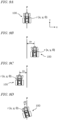
- FIGS. 12A, 12B, and 12C are diagrams schematically showing examples of the work vehicle 100 traveling by using the obstacle detection system.
- the work vehicle 100 automatically travels on a road outside the field.
- the work vehicle 100 is automatically traveling while sensing the surrounding environment with at least one LiDAR sensor 140 and at least one camera 120.
- the work vehicle 100 is automatically traveling while sensing the surrounding environment by using the LiDAR sensor 140a provided at the front of the work vehicle 100 and the camera 120a provided at the front of the work vehicle 100.
- sensing by the LiDAR sensor 140a is shown schematically with arrows, and the sensing region by the camera 120a is shown schematically as a gray triangle.
- the controller 180 detects the obstacle candidate 40 based on data that is output from the LiDAR sensor 140a.
- the controller 180 does not perform any process that uses the image captured by the camera 120a (i.e., any process for detecting the obstacle candidate).
- the controller 180 may selectively use (and activate, if necessary) one or more cameras 120 suitable for capturing the obstacle candidate 40 having been detected, and may have an image of the obstacle candidate 40 captured.
- the cameras 120 may include an actuator or other mechanisms to change their orientation.
- the controller 180 may change the orientation of the camera (s) 120 so that the field of view of the selected camera 120 includes the obstacle candidate 40.
- the camera 120c is activated in addition to the camera 120a, which was activated before detection of the obstacle candidate 40, and the cameras 120a and 120c are employed to capture the obstacle candidate 40.
- the controller 180 may cause the cameras 120a and/or 120c to capture an image of the obstacle candidate 40 at a higher magnification than when capturing the surrounding environment before detection of the obstacle candidate 40.
- the controller 180 may cause them to capture an image of the obstacle candidate 40 at a higher resolution than when capturing the surrounding environment before detection of the obstacle candidate 40, or at a higher frame rate than when capturing the surrounding environment before detection of the obstacle candidate 40.
- the controller 180 determines whether or not to change the traveling status of the work vehicle 100 based on the images of the obstacle candidate 40 acquired with the cameras 120a and 120c.
- the controller 180 determines whether or not to change the traveling status of the work vehicle 100 so that the work vehicle 100 avoids contact with or approach to the obstacle candidate 40, by a recognition processing based on the images of the obstacle candidate 40 acquired with the cameras 120a and 120c.
- FIG. 12C shows an example of determining to change the target path of the work vehicle 100 so as to avoid the obstacle candidate 40.
- a new target path 32 for the work vehicle 100 is set by a plurality of waypoints 32p that are newly set so as to avoid the obstacle candidate 40.
- the obstacle detection system it is possible to detect obstacles with good accuracy while reducing the processing load for obstacle detection. For example, if obstacles are to be detected by constantly using image data, the camera(s) will need to continuously acquire high-quality (high resolution) images, and the processing load for obstacle detection by using image data can be high.
- the power consumption of the controller performing the process of obstacle detection using image recognition techniques may also increase.
- an agricultural machine is monitored or operated remotely, it is necessary to continuously transmit images acquired with the camera(s) via a network while the agricultural machine is traveling, which may increase the amount of communication.
- the controller 180 detects obstacle candidates based on data that is output from the LiDAR sensor(s) 140, begins to scrutinize an obstacle candidate with image data only upon detection of the obstacle candidate, and determines whether the obstacle candidate should cause a change in the traveling status of the work vehicle 100 or not. This allows for reducing the processing load for obstacle detection. Because obstacle candidates are detected in advance based on data that is output from the LiDAR sensor(s) 140, the camera(s) 120 can acquire images while focusing on a necessary range or subjects, which can reduce the processing load for obstacle detection while maintaining the accuracy of obstacle detection.
- obstacles can be detected with good accuracy using both data that is output from the LiDAR sensor (s) 140 and image data that is captured by the camera (s) 120. Obstacles can be detected with good accuracy by using both of: data that is output from the LiDAR sensor(s) 140, which provides a distance to an object and a positional relationship with the obj ect with high accuracy; and image data, which allows for performing object detection by using an image recognition technique.
- image data may be transmitted via the network 80 to, for example, the management device 600 or the terminal device 400 only upon detection of an obstacle candidate, whereby an excessive increase in the amount of communication can be suppressed.
- Detecting an obstacle with high accuracy includes, for example, suppressing misdetection of obstacles, reducing errors in the obstacle positions, reducing failures to detect obstacles which should have been detected, and so on.
- suppressing misdetection of obstacles can reduce unnecessary changes in the traveling status of the work vehicle 100 (e.g., reduction of traveling speed, halting, change of the target path, etc.) that may be caused by misdetection of obstacles.
- the efficiency of movement through automatic travel by the work vehicle 100 and/or agricultural work performed by the work vehicle 100 can be increased.
- the controller 180 detects one or more objects in the surrounding environment of the work vehicle 100 based on data that is output from the LiDAR sensor(s) 140.
- the controller 180 determines that the detected object is an obstacle candidate
- the controller 180 causes the camera(s) 120 to acquire an image(s) of the obstacle candidate, and determines whether or not to change the traveling status of the work vehicle 100 based on the image (s) acquired with the camera (s) 120.
- the controller 180 may determine whether the detected object is an obstacle candidate by referring to an environment map and/or a target path in addition to the data that is output from the LiDAR sensor(s) 140.
- the environment map and the target path are stored, for example, in the storage device 170 of the work vehicle 100.
- the controller 180 may obtain the environment map and the target path from the management device 600 or the terminal device 400 in determining whether the detected object is an obstacle candidate or not.
- the work vehicle 100 exemplified here is a tractor to which an implement is attachable.
- the controller 180 may set the region to be scanned by the LiDAR sensor(s) 140 (i.e. the region to be sensed for detecting an obstacle candidate) based on the type of the attached implement.
- the shape of the region to be scanned for detecting an obstacle candidate may be set depending on the characteristics of the attached implement (e.g., width, height, weight, or horsepower).
- the type and/or characteristics of the implement attached to the work vehicle 100 are recorded in, for example, the storage device 170 of the work vehicle 100 . They may be automatically recognized and recorded when the implement becomes connected to the work vehicle 100 .
- the region scanned by the LiDAR sensor(s) 140 may be set depending on the location or the environment in which the work vehicle 100 travels. For example, when the work vehicle 100 travels straight on a road inside or outside a field, the front of the work vehicle 100 may be sensed mainly, as in the example shown in FIG. 12A .
- FIG. 13 schematically shows another example of the work vehicle 100 traveling by using the obstacle detection system.
- FIG. 13 shows an enlarged view of the region enclosed by the dotted line in FIG. 7 , where the work vehicle 100 is automatically traveling in the field. For example, as in the example shown in FIG.
- the LiDAR sensors 140a to 140d when the work vehicle 100 is traveling along a target path in the field and is about to travel along a turning path P2 from the work area 72 to a headland 74 , it is preferable to use the LiDAR sensors 140a to 140d to sense the front, rear, left and right of the work vehicle 100 .
- the sensing regions by the LiDAR sensors 140a to 140d are schematically shown in gray fan shapes.
- the work vehicle 100 is illustrated as performing self-driving while sensing the surrounding environment with the LiDAR sensor(s) 140 and the camera(s) 120 which the work vehicle 100 includes, this is not a limitation.
- the work vehicle 100 may perform self -driving while sensing the surrounding environment with a LiDAR sensor (s) and a camera (s) which are included in any other movable unit, such as an agricultural machine that is distinct from the work vehicle 100 , or a drone (Unmanned Aerial Vehicle: UAV).
- the controller 180 may function as an obstacle detection system that works in cooperation with the LiDAR sensor(s) and camera(s) included in the other movable unit.
- the work vehicle 100 may perform self-driving and agricultural work by using the obstacle detection system.
- the controller 180 functions as a controller of an obstacle detection system.
- a plurality of ECUs included in the controller 180 may cooperate with each other to perform the processes .
- the controller 180 may further include ECUs to perform a portion of, or the entirety of, the processes for detecting obstacles in addition to the exemplified ECUs 181 to 186 .
- a portion of, or the entirety of the processes performed by the controller 180 in the obstacle detection system may be performed by other devices.
- Such other devices may be any of the management device 600 (the processor 660 ), the terminal device 400 (the processor 460 ), and the operational terminal 200 .
- the combination of the controller 180 and the management device 600 functions as a controller of the obstacle detection system.
- determining whether or not to change the traveling status of the work vehicle 100 means that the controller 180 and/or the other device(s) mentioned above perform processes using the image(s) of the obstacle candidate acquired with the camera (s) 120 in order to determine whether or not to change the traveling status of the work vehicle 100 . More specifically, the device itself determines whether or not to change the traveling status of the work vehicle 100 by using image recognition techniques such as object detection. Known algorithms may be used for object detection.
- the image(s) of the obstacle candidate acquired with the camera (s) 120 is transmitted to an external device (e.g., a computer remotely monitoring the work vehicle 100 ), and it may be determined whether or not to change the traveling status of the work vehicle 100 based on a signal regarding whether or not to change the traveling status of the work vehicle 100 that is received from the external device. For example, a user who has examined the image(s) of the obstacle candidate acquired with the camera(s) 120 may input to the external device a signal regarding whether or not to change the traveling status of the work vehicle 100 .
- an external device e.g., a computer remotely monitoring the work vehicle 100
- a user who has examined the image(s) of the obstacle candidate acquired with the camera(s) 120 may input to the external device a signal regarding whether or not to change the traveling status of the work vehicle 100 .
- the obstacle detection system may be used while the work vehicle 100 is automatically traveling in the field or on a road outside the field (a general road or an agricultural road) .
- the work vehicle 100 automatically travels on a road inside or outside the field along the target path, for example.
- possible obstacles for which the work vehicle 100 should change its traveling status in order to avoid collision or contact may include, for example: what is inside the field, e.g., animals or persons entering the field, persons working in the field, other agricultural machines traveling in the field, and trees in the field; and, as for roads outside the field (especially agricultural roads), for example, persons or other agricultural machines traveling on the roads, animals or trees existing on the roads, and the like.
- the controller 180 may detect any object higher than a predetermined height as an obstacle candidate based on data that is output from the LiDAR sensor(s) 140 while the work vehicle 100 is traveling inside the field or on an agricultural road.
- the predetermined height may be set based on the type or characteristics (e.g., height, weight, horsepower, etc.) of the work vehicle 100 (inclusive of, when the work vehicle 100 has an implement attached thereto, that implement as well).
- the predetermined height may be changed depending on whether the work vehicle 100 is traveling inside the field or outside the field.
- the controller 180 may be configured to identify the type of the object assumed as an obstacle candidate based on the image of the obstacle candidate acquired with the camera(s) 120 , and if the obstacle candidate is a person or an animal, cause the work vehicle 100 to stop traveling or change the target path of the work vehicle 100 so as to avoid the obstacle candidate.
- Grass e.g., weeds
- trees may also be overgrown in the field or on roads outside the field (especially agricultural roads).
- the controller 180 may identify the type of the object assumed to be an obstacle candidate based on RGB values of a color image(s) of the obstacle candidate acquired with the camera(s) 120 , for example.
- the controller 180 may identify whether the obstacle candidate is vegetation or not by detecting green pixels using the RGB values of the color image data of the obstacle candidate. For example, the controller 180 may detect leaves of vegetation by detecting green pixels from the color image data containing the obstacle candidate and exclude the green pixels from the subject of recognition processing.
- the controller 180 may cause the work vehicle 100 to stop traveling or to decelerate upon detecting the obstacle candidate as a trigger. That is, the controller 180 may cause the work vehicle 100 to stop traveling or to decelerate at the time when an obstacle candidate is detected, before even determining whether or not to change the traveling status of the work vehicle 100 . After determining that the traveling status of the work vehicle 100 is not to be changed, the controller 180 cause the work vehicle 100 to resume traveling or to accelerate.
- FIG. 14 is a flowchart showing an example of steps by which the controller 180 detects obstacles.
- an obstacle candidate is detected based on the data that is output from the LiDAR sensor(s) 140 .
- the controller 180 detects the obstacle candidate referring to, for example, the environment map and/or the target path in addition to the data that is output from the LiDAR sensor(s) 140 .
- the controller 180 may further obtain, based on the data that is output from the LiDAR sensor(s) 140 , a distance between the detected obstacle candidate and the work vehicle 100 , a positional relationship between the detected obstacle candidate and the work vehicle 100 , and so on.
- step S142 the camera(s) 120 acquires the image of the obstacle candidate, upon detecting the obstacle candidate in step S141 as a trigger.
- the work vehicle 100 is traveling while sensing the surrounding environment with the camera(s) 120 (e.g., capturing the surrounding environment with the camera(s) 120 ), even the detection of the obstacle candidate.
- the controller 180 may cause the camera (s) 120 to capture the obstacle candidate at a higher magnification than that of the image (s) of the surrounding environment captured with the camera(s) 120 before the detection of the obstacle candidate.
- the controller 180 may perform the below process before causing the camera(s) 120 to capture an image(s) of the obstacle candidate.
- the obstacle candidate when the obstacle candidate is detected, it may be detected whether the obstacle candidate is included in the field of view of a camera 120 or not, and if the obstacle candidate is not included in the field of view of the camera 120 , the orientation of the camera 120 may be changed so that the field of view of the camera 120 includes the obstacle candidate.
- the controller 180 may turn on the lighting device 230 to illuminate the surrounding environment of the work vehicle 100 , or increase the illuminance of the lighting device 230 .
- the work vehicle 100 may further include one or more illuminance sensors.
- the controller 180 by judging whether or not a measurement value(s) of the illuminance measured by the illuminance sensor (s) of the work vehicle 100 is lower than or equal to a threshold, and if the measurement value(s) is lower than or equal to the threshold, may turn on the lighting device 230 or increase the illuminance of the lighting device 230 .
- the controller 180 may change the orientation of the lighting device 230 so that the lighting device 230 illuminates the detected obstacle candidate.
- step S143 it is determined whether or not to change the traveling status of the work vehicle 100 based on the image(s) acquired with the camera(s) 120 in step S142 .
- the controller 180 may use one, or a combination, of factors including: the type of the detected obstacle candidate; the distance between the obstacle candidate and the work vehicle 100; the positional relationship between the obstacle candidate and the work vehicle 100; the size of the obstacle candidate; the speed and other traveling status of the work vehicle at the time the obstacle candidate is detected; and so on.
- the conditions for determining whether or not to change the traveling status of the work vehicle 100 may be varied depending on whether the work vehicle 100 is traveling in the field, on an agricultural road outside the field, or on a general road outside the field.
- step S143 If it is determined in step S143 that the traveling status of the work vehicle 100 is to be changed, the traveling status of the work vehicle 100 is changed at step S144 . If it is determined in step S143 that the traveling status of the work vehicle 100 is not to be changed, it ends without changing the traveling status of the work vehicle 100 .
- FIG. 15 is a flowchart showing another example of steps by which the controller 180 detects obstacles. Differences from the example of FIG. 14 are mainly explained below.
- the controller 180 when an obstacle candidate is detected based on the data that is output from the LiDAR sensor(s) 140 (step S151 ), acquires an image(s) of the obstacle candidate by the camera(s) 120 (step S152 ).
- the controller 180 performs the obstacle recognition process by using the image (s) acquired with the camera (s) 120 (step S153 ) and determines whether or not to change the traveling status of the work vehicle 100 (step S154 ).
- the ECU 185 determines whether a detour path that allows for avoiding the obstacle is generable (step S155 ). For example, as in the example of FIG. 12C , if the road traveled by the work vehicle 100 has any space available for detouring, it is determined that a detour path is generable. While the work vehicle 100 is traveling in the field, for example, if a detouring path that does not affect the agricultural work and crops is generable, it is determined that a detour path is generable.
- a detour path is not generable. For example, if it is possible to generate a detour path such that the detour path does not enter the already worked area in the field, it is determined that a detour path is generable.
- the ECU 185 When it is determined that a detour path is generable, the ECU 185 generates the detour path by changing the local path so as to avoid the obstacle, and the controller 180 causes the work vehicle 100 to travel along the detour path (step S156 ). When it is determined that a detour path is not generable, the controller 180 causes the work vehicle 100 to stop (step S157) . In parallel, the controller 180 may perform the generation of a warning sound from the buzzer 220 , and the transmission of a warning signal to the terminal device 400 .
- step S158 If the object that is detected as an obstacle (e.g., a movable obstacle such as a person or animal) has moved, or the worker has removed the obstacle so that the obstacle is determined as no longer present (step S158 ), and the controller 180 causes the work vehicle 100 to resume traveling (step S159 ). The controller 180 repeats the operations of steps S151 to S159 until a command to end the operation is issued.
- an obstacle e.g., a movable obstacle such as a person or animal
- the present disclosure encompasses obstacle detection systems, agricultural machines, and obstacle detection methods as recited in the following Items.
- an obstacle can be detected with good accuracy while reducing the processing load for obstacle detection.
- An obstacle detection system with the above configuration is able to detect an obstacle with good accuracy even at nighttime, for example.
- An obstacle detection system with the above configuration is applicable to various agricultural machines (including implements attached to the agricultural machines).
- An agricultural machine comprising the obstacle detection system of any one of Items 1 to 12, the LiDAR sensor, and the camera.
- An obstacle detection method for an agricultural machine to perform self-driving while sensing a surrounding environment with a LiDAR sensor and a camera comprising:
- the obstacle can be detected with good accuracy while reducing the processing load for obstacle detection.
- the present techniques according to the present disclosure are applicable to obstacle detection systems for agricultural machines such as tractors, harvesters, rice transplanters, vehicles for crop management, vegetable transplanters, mowers, seeders, spreaders, or agricultural robots.
- 40 obstacle, 50: GNSS satellite; 60: reference station; 70: field; 72: work area; 74: headland; 76: road; 80: network; 100: work vehicle; 101: vehicle body; 102: prime mover (engine); 103: transmission; 104: wheel; 105: cabin; 106: steering device; 107: driver's seat; 108: linkage; 110: positioning device (GNSS unit) ; 111: GNSS receiver; 112: RTK receiver; 115: inertial measurement unit (IMU); 116: processing circuit; 120: camera; 130: obstacle sensor; 140: LiDAR sensor; 150: sensors; 152: steering wheel sensor; 154: angle-of-turn sensor; 156: axle sensor; 160: control system; 170: storage device; 180: controller; 181-186: ECU; 190: communication device; 200: operational terminal; 210: operation switches; 220: buzzer; 230: lighting device; 240: drive device; 300: implement; 340: drive device; 380: controller;
Landscapes
- Engineering & Computer Science (AREA)
- Physics & Mathematics (AREA)
- General Physics & Mathematics (AREA)
- Radar, Positioning & Navigation (AREA)
- Remote Sensing (AREA)
- Electromagnetism (AREA)
- Automation & Control Theory (AREA)
- Computer Networks & Wireless Communication (AREA)
- Aviation & Aerospace Engineering (AREA)
- Multimedia (AREA)
- Theoretical Computer Science (AREA)
- Life Sciences & Earth Sciences (AREA)
- Mechanical Engineering (AREA)
- Soil Sciences (AREA)
- Environmental Sciences (AREA)
- Guiding Agricultural Machines (AREA)
- Control Of Position, Course, Altitude, Or Attitude Of Moving Bodies (AREA)
Applications Claiming Priority (2)
| Application Number | Priority Date | Filing Date | Title |
|---|---|---|---|
| JP2021210793 | 2021-12-24 | ||
| PCT/JP2022/043045 WO2023119996A1 (ja) | 2021-12-24 | 2022-11-21 | 障害物検出システム、農業機械および障害物検出方法 |
Publications (3)
| Publication Number | Publication Date |
|---|---|
| EP4445708A1 true EP4445708A1 (de) | 2024-10-16 |
| EP4445708A4 EP4445708A4 (de) | 2025-03-26 |
| EP4445708B1 EP4445708B1 (de) | 2026-04-08 |
Family
ID=86902237
Family Applications (1)
| Application Number | Title | Priority Date | Filing Date |
|---|---|---|---|
| EP22910714.9A Active EP4445708B1 (de) | 2021-12-24 | 2022-11-21 | Hinderniserkennungssystem, landwirtschaftliche maschine und hinderniserkennungsverfahren |
Country Status (4)
| Country | Link |
|---|---|
| US (1) | US20240338033A1 (de) |
| EP (1) | EP4445708B1 (de) |
| JP (1) | JPWO2023119996A1 (de) |
| WO (1) | WO2023119996A1 (de) |
Families Citing this family (6)
| Publication number | Priority date | Publication date | Assignee | Title |
|---|---|---|---|---|
| US12479481B2 (en) * | 2019-12-23 | 2025-11-25 | Mitsubishi Electric Corporation | Obstacle detection device and obstacle detection method |
| DE102023130883A1 (de) * | 2023-11-08 | 2025-05-08 | Claas Kommanditgesellschaft auf Aktien mbH | Landwirtschaftliche Arbeitsmaschine |
| DE102023130882A1 (de) * | 2023-11-08 | 2025-05-08 | Claas Kommanditgesellschaft auf Aktien mbH | Landwirtschaftliche Arbeitsmaschine |
| KR20250131218A (ko) * | 2024-02-26 | 2025-09-02 | 얀마 홀딩스 주식회사 | 제어 방법, 제어 프로그램, 및 제어 시스템 |
| CN121464770A (zh) * | 2024-12-09 | 2026-02-06 | 北京晨飞和合科技有限公司 | 一种基于环境感知的无人驾驶农用机械 |
| CN119611035A (zh) * | 2025-02-11 | 2025-03-14 | 江苏岚江智能科技有限公司 | 一种履带式混合动力智能果园作业机器人及其方法 |
Family Cites Families (29)
| Publication number | Priority date | Publication date | Assignee | Title |
|---|---|---|---|---|
| JP2819551B2 (ja) * | 1987-08-12 | 1998-10-30 | 日産自動車株式会社 | 自律走行車両制御装置 |
| US9234618B1 (en) * | 2012-09-27 | 2016-01-12 | Google Inc. | Characterizing optically reflective features via hyper-spectral sensor |
| KR101644370B1 (ko) * | 2014-10-23 | 2016-08-01 | 현대모비스 주식회사 | 물체 검출 장치 및 그 동작 방법 |
| CN104765367B (zh) * | 2014-11-27 | 2015-12-02 | 无锡美联动线智能科技有限公司 | 实现智能化越障的服务机器人 |
| JP6626669B2 (ja) * | 2015-09-04 | 2019-12-25 | 株式会社日立情報通信エンジニアリング | カメラ制御システム、及び、カメラ制御方法 |
| EP3572897B1 (de) * | 2017-01-20 | 2025-01-29 | Kubota Corporation | Nutzfahrzeug |
| JP6680701B2 (ja) * | 2017-01-20 | 2020-04-15 | 株式会社クボタ | 作業車 |
| JP6914065B2 (ja) * | 2017-03-17 | 2021-08-04 | シャープ株式会社 | 障害物検出装置、走行装置、障害物検出システムおよび障害物検出方法 |
| US20180288320A1 (en) * | 2017-04-03 | 2018-10-04 | Uber Technologies, Inc. | Camera Fields of View for Object Detection |
| DE102017122711A1 (de) * | 2017-09-29 | 2019-04-04 | Claas E-Systems Kgaa Mbh & Co. Kg | Verfahren für den Betrieb einer selbstfahrenden landwirtschaftlichen Arbeitsmaschine |
| JP6962166B2 (ja) * | 2017-12-11 | 2021-11-05 | 井関農機株式会社 | 作業車両の遠隔操作システム |
| JP2019152924A (ja) * | 2018-02-28 | 2019-09-12 | 学校法人立命館 | 自己位置同定システム、車両、及び処理装置 |
| US11119478B2 (en) * | 2018-07-13 | 2021-09-14 | Waymo Llc | Vehicle sensor verification and calibration |
| JP7044694B2 (ja) * | 2018-12-27 | 2022-03-30 | ヤンマーパワーテクノロジー株式会社 | 作業車両用の障害物検知システム |
| JP7225009B2 (ja) * | 2019-04-03 | 2023-02-20 | アルパイン株式会社 | 投影装置、プログラム、モビリティ |
| JP7195543B2 (ja) | 2019-04-26 | 2022-12-26 | 国立大学法人京都大学 | 収穫機 |
| JP7565677B2 (ja) * | 2019-06-27 | 2024-10-11 | 株式会社クボタ | 農作業車のための障害物検出システム |
| US11778934B2 (en) * | 2019-07-02 | 2023-10-10 | Bear Flag Robotics, Inc. | Agricultural lane following |
| JP7349277B2 (ja) * | 2019-07-10 | 2023-09-22 | ヤンマーパワーテクノロジー株式会社 | 作業車両用の自動走行システム |
| JP2021029218A (ja) | 2019-08-29 | 2021-03-01 | 井関農機株式会社 | 農道経路情報格納システムおよび作業車両 |
| JP2021094118A (ja) * | 2019-12-16 | 2021-06-24 | 日立グローバルライフソリューションズ株式会社 | 自律走行型掃除機 |
| US11493922B1 (en) * | 2019-12-30 | 2022-11-08 | Waymo Llc | Perimeter sensor housings |
| US11557127B2 (en) * | 2019-12-30 | 2023-01-17 | Waymo Llc | Close-in sensing camera system |
| CN115867767A (zh) * | 2020-01-03 | 2023-03-28 | 御眼视觉技术有限公司 | 用于车辆导航的系统和方法 |
| JP2021113767A (ja) * | 2020-01-21 | 2021-08-05 | フォルシアクラリオン・エレクトロニクス株式会社 | 障害物検知装置、及び障害物検知システム |
| US11113584B2 (en) * | 2020-02-04 | 2021-09-07 | Nio Usa, Inc. | Single frame 4D detection using deep fusion of camera image, imaging RADAR and LiDAR point cloud |
| JP7373746B2 (ja) * | 2020-03-13 | 2023-11-06 | パナソニックIpマネジメント株式会社 | 自律走行型掃除機、自律走行型掃除機の制御方法、及び、プログラム |
| CN212556197U (zh) * | 2020-09-21 | 2021-02-19 | 李山江 | 一种自动刹车系统 |
| US11835923B2 (en) * | 2020-11-06 | 2023-12-05 | Maxar Mission Solutions Inc. | Imaging through scattering media |
-
2022
- 2022-11-21 EP EP22910714.9A patent/EP4445708B1/de active Active
- 2022-11-21 JP JP2023569185A patent/JPWO2023119996A1/ja active Pending
- 2022-11-21 WO PCT/JP2022/043045 patent/WO2023119996A1/ja not_active Ceased
-
2024
- 2024-06-18 US US18/746,108 patent/US20240338033A1/en active Pending
Also Published As
| Publication number | Publication date |
|---|---|
| EP4445708B1 (de) | 2026-04-08 |
| EP4445708A4 (de) | 2025-03-26 |
| US20240338033A1 (en) | 2024-10-10 |
| JPWO2023119996A1 (de) | 2023-06-29 |
| WO2023119996A1 (ja) | 2023-06-29 |
Similar Documents
| Publication | Publication Date | Title |
|---|---|---|
| EP4445708B1 (de) | Hinderniserkennungssystem, landwirtschaftliche maschine und hinderniserkennungsverfahren | |
| US20240302845A1 (en) | Path-planning system for self-driving agricultural machine | |
| US12509091B2 (en) | Agricultural road identification system, control system, and agricultural machine | |
| US20250100450A1 (en) | Video display system and work vehicle | |
| US12585286B2 (en) | Map generation system and map generation method | |
| EP4434313A1 (de) | Landwirtschaftliche maschine, messsystem zur verwendung in einer landwirtschaftlichen maschine und messverfahren | |
| EP4538819A1 (de) | Nutzfahrzeug, steuerungsverfahren und steuerungssystem | |
| US20250117021A1 (en) | Travel control system, agricultural machine and travel control method | |
| US20250089596A1 (en) | Agricultural management system | |
| US20240341215A1 (en) | Agricultural machine, sensing system, sensing method, remote operation system, and control method | |
| JPWO2023112515A5 (de) | ||
| US20240337753A1 (en) | Agricultural machine, sensing system for use in agricultural machine, and sensing method | |
| US20250085432A1 (en) | Sensing system, agricultural machine, and sensing device | |
| JP7709409B2 (ja) | 農業機械の自動走行のための経路生成システムおよび経路生成方法 | |
| US20250143200A1 (en) | Travel control system, travel control method, and computer program | |
| EP4537645A1 (de) | Routenerzeugungssystem und routenerzeugungsverfahren zur automatisierten fahrt einer landwirtschaftlichen maschine | |
| EP4449841A1 (de) | Landwirtschaftliche maschine und gestenerkennungssystem für eine landwirtschaftliche maschine |
Legal Events
| Date | Code | Title | Description |
|---|---|---|---|
| STAA | Information on the status of an ep patent application or granted ep patent |
Free format text: STATUS: THE INTERNATIONAL PUBLICATION HAS BEEN MADE |
|
| PUAI | Public reference made under article 153(3) epc to a published international application that has entered the european phase |
Free format text: ORIGINAL CODE: 0009012 |
|
| STAA | Information on the status of an ep patent application or granted ep patent |
Free format text: STATUS: REQUEST FOR EXAMINATION WAS MADE |
|
| 17P | Request for examination filed |
Effective date: 20240712 |
|
| AK | Designated contracting states |
Kind code of ref document: A1 Designated state(s): AL AT BE BG CH CY CZ DE DK EE ES FI FR GB GR HR HU IE IS IT LI LT LU LV MC ME MK MT NL NO PL PT RO RS SE SI SK SM TR |
|
| REG | Reference to a national code |
Free format text: PREVIOUS MAIN CLASS: A01B0069000000 Ipc: G05D0001242000 Ref country code: DE Ref legal event code: R079 Ref document number: 602022034352 Country of ref document: DE |
|
| A4 | Supplementary search report drawn up and despatched |
Effective date: 20250221 |
|
| RIC1 | Information provided on ipc code assigned before grant |
Ipc: A01B 69/00 20060101ALI20250217BHEP Ipc: G06V 20/58 20220101ALI20250217BHEP Ipc: G06V 10/56 20220101ALI20250217BHEP Ipc: G06V 10/141 20220101ALI20250217BHEP Ipc: G05D 111/10 20240101ALI20250217BHEP Ipc: G05D 109/10 20240101ALI20250217BHEP Ipc: G05D 107/20 20240101ALI20250217BHEP Ipc: G05D 1/622 20240101ALI20250217BHEP Ipc: G05D 105/15 20240101ALI20250217BHEP Ipc: G05D 1/243 20240101ALI20250217BHEP Ipc: G01S 17/931 20200101ALI20250217BHEP Ipc: G01S 17/86 20200101ALI20250217BHEP Ipc: G01S 17/42 20060101ALI20250217BHEP Ipc: A01B 69/04 20060101ALI20250217BHEP Ipc: G05D 1/242 20240101AFI20250217BHEP |
|
| DAV | Request for validation of the european patent (deleted) | ||
| DAX | Request for extension of the european patent (deleted) | ||
| GRAP | Despatch of communication of intention to grant a patent |
Free format text: ORIGINAL CODE: EPIDOSNIGR1 |
|
| STAA | Information on the status of an ep patent application or granted ep patent |
Free format text: STATUS: GRANT OF PATENT IS INTENDED |
|
| RIC1 | Information provided on ipc code assigned before grant |
Ipc: G05D 1/242 20240101AFI20251127BHEP Ipc: A01B 69/04 20060101ALI20251127BHEP Ipc: G01S 17/42 20060101ALI20251127BHEP Ipc: G01S 17/86 20200101ALI20251127BHEP Ipc: G01S 17/931 20200101ALI20251127BHEP Ipc: G05D 1/243 20240101ALI20251127BHEP Ipc: G05D 105/15 20240101ALI20251127BHEP Ipc: G05D 1/622 20240101ALI20251127BHEP Ipc: G05D 107/20 20240101ALI20251127BHEP Ipc: G05D 109/10 20240101ALI20251127BHEP Ipc: G05D 111/10 20240101ALI20251127BHEP Ipc: G06V 10/141 20220101ALI20251127BHEP Ipc: G06V 10/56 20220101ALI20251127BHEP Ipc: G06V 20/58 20220101ALI20251127BHEP Ipc: A01B 69/00 20060101ALI20251127BHEP |
|
| INTG | Intention to grant announced |
Effective date: 20251211 |
|
| GRAS | Grant fee paid |
Free format text: ORIGINAL CODE: EPIDOSNIGR3 |
|
| GRAA | (expected) grant |
Free format text: ORIGINAL CODE: 0009210 |
|
| STAA | Information on the status of an ep patent application or granted ep patent |
Free format text: STATUS: THE PATENT HAS BEEN GRANTED |
|
| AK | Designated contracting states |
Kind code of ref document: B1 Designated state(s): AL AT BE BG CH CY CZ DE DK EE ES FI FR GB GR HR HU IE IS IT LI LT LU LV MC ME MK MT NL NO PL PT RO RS SE SI SK SM TR |
|
| REG | Reference to a national code |
Ref country code: CH Ref legal event code: F10 Free format text: ST27 STATUS EVENT CODE: U-0-0-F10-F00 (AS PROVIDED BY THE NATIONAL OFFICE) Effective date: 20260408 Ref country code: GB Ref legal event code: FG4D |
|
| REG | Reference to a national code |
Ref country code: DE Ref legal event code: R096 Ref document number: 602022034352 Country of ref document: DE |