EP4443007A1 - Turbomolekularpumpe - Google Patents
Turbomolekularpumpe Download PDFInfo
- Publication number
- EP4443007A1 EP4443007A1 EP24193842.2A EP24193842A EP4443007A1 EP 4443007 A1 EP4443007 A1 EP 4443007A1 EP 24193842 A EP24193842 A EP 24193842A EP 4443007 A1 EP4443007 A1 EP 4443007A1
- Authority
- EP
- European Patent Office
- Prior art keywords
- pump
- turbomolecular
- turbomolecular pump
- cooling element
- rotor
- Prior art date
- Legal status (The legal status is an assumption and is not a legal conclusion. Google has not performed a legal analysis and makes no representation as to the accuracy of the status listed.)
- Pending
Links
Images



Classifications
-
- F—MECHANICAL ENGINEERING; LIGHTING; HEATING; WEAPONS; BLASTING
- F04—POSITIVE - DISPLACEMENT MACHINES FOR LIQUIDS; PUMPS FOR LIQUIDS OR ELASTIC FLUIDS
- F04D—NON-POSITIVE-DISPLACEMENT PUMPS
- F04D19/00—Axial-flow pumps
- F04D19/02—Multi-stage pumps
- F04D19/04—Multi-stage pumps specially adapted to the production of a high vacuum, e.g. molecular pumps
-
- F—MECHANICAL ENGINEERING; LIGHTING; HEATING; WEAPONS; BLASTING
- F04—POSITIVE - DISPLACEMENT MACHINES FOR LIQUIDS; PUMPS FOR LIQUIDS OR ELASTIC FLUIDS
- F04D—NON-POSITIVE-DISPLACEMENT PUMPS
- F04D19/00—Axial-flow pumps
- F04D19/02—Multi-stage pumps
- F04D19/04—Multi-stage pumps specially adapted to the production of a high vacuum, e.g. molecular pumps
- F04D19/042—Turbomolecular vacuum pumps
-
- F—MECHANICAL ENGINEERING; LIGHTING; HEATING; WEAPONS; BLASTING
- F04—POSITIVE - DISPLACEMENT MACHINES FOR LIQUIDS; PUMPS FOR LIQUIDS OR ELASTIC FLUIDS
- F04D—NON-POSITIVE-DISPLACEMENT PUMPS
- F04D29/00—Details, component parts, or accessories
- F04D29/02—Selection of particular materials
- F04D29/023—Selection of particular materials especially adapted for elastic fluid pumps
-
- F—MECHANICAL ENGINEERING; LIGHTING; HEATING; WEAPONS; BLASTING
- F04—POSITIVE - DISPLACEMENT MACHINES FOR LIQUIDS; PUMPS FOR LIQUIDS OR ELASTIC FLUIDS
- F04D—NON-POSITIVE-DISPLACEMENT PUMPS
- F04D29/00—Details, component parts, or accessories
- F04D29/40—Casings; Connections of working fluid
- F04D29/52—Casings; Connections of working fluid for axial pumps
- F04D29/522—Casings; Connections of working fluid for axial pumps especially adapted for elastic fluid pumps
-
- F—MECHANICAL ENGINEERING; LIGHTING; HEATING; WEAPONS; BLASTING
- F04—POSITIVE - DISPLACEMENT MACHINES FOR LIQUIDS; PUMPS FOR LIQUIDS OR ELASTIC FLUIDS
- F04D—NON-POSITIVE-DISPLACEMENT PUMPS
- F04D29/00—Details, component parts, or accessories
- F04D29/58—Cooling; Heating; Diminishing heat transfer
- F04D29/582—Cooling; Heating; Diminishing heat transfer specially adapted for elastic fluid pumps
- F04D29/584—Cooling; Heating; Diminishing heat transfer specially adapted for elastic fluid pumps cooling or heating the machine
-
- F—MECHANICAL ENGINEERING; LIGHTING; HEATING; WEAPONS; BLASTING
- F04—POSITIVE - DISPLACEMENT MACHINES FOR LIQUIDS; PUMPS FOR LIQUIDS OR ELASTIC FLUIDS
- F04D—NON-POSITIVE-DISPLACEMENT PUMPS
- F04D29/00—Details, component parts, or accessories
- F04D29/58—Cooling; Heating; Diminishing heat transfer
- F04D29/582—Cooling; Heating; Diminishing heat transfer specially adapted for elastic fluid pumps
- F04D29/5853—Cooling; Heating; Diminishing heat transfer specially adapted for elastic fluid pumps heat insulation or conduction
-
- F—MECHANICAL ENGINEERING; LIGHTING; HEATING; WEAPONS; BLASTING
- F05—INDEXING SCHEMES RELATING TO ENGINES OR PUMPS IN VARIOUS SUBCLASSES OF CLASSES F01-F04
- F05D—INDEXING SCHEME FOR ASPECTS RELATING TO NON-POSITIVE-DISPLACEMENT MACHINES OR ENGINES, GAS-TURBINES OR JET-PROPULSION PLANTS
- F05D2300/00—Materials; Properties thereof
- F05D2300/10—Metals, alloys or intermetallic compounds
- F05D2300/12—Light metals
- F05D2300/121—Aluminium
-
- F—MECHANICAL ENGINEERING; LIGHTING; HEATING; WEAPONS; BLASTING
- F05—INDEXING SCHEMES RELATING TO ENGINES OR PUMPS IN VARIOUS SUBCLASSES OF CLASSES F01-F04
- F05D—INDEXING SCHEME FOR ASPECTS RELATING TO NON-POSITIVE-DISPLACEMENT MACHINES OR ENGINES, GAS-TURBINES OR JET-PROPULSION PLANTS
- F05D2300/00—Materials; Properties thereof
- F05D2300/50—Intrinsic material properties or characteristics
- F05D2300/502—Thermal properties
- F05D2300/5024—Heat conductivity
Definitions
- the invention relates to a turbomolecular pump with a housing, several turbomolecular pumping stages and at least one pre-pumping stage which is arranged downstream of the turbomolecular pumping stages.
- Turbomolecular pumps are usually operated at a rotor speed that is in a range above 10,000 revolutions per minute. Since the pumping elements of a turbomolecular pump, i.e. its rotor and stator, usually do not have good thermal contact with the housing of the turbomolecular pump, the rotor heats up considerably when the turbomolecular pump is in operation. Rotor temperatures of 90°C and more are reached. A permanently high rotor temperature can lead to damage within the turbomolecular pump and thus shorten its service life.
- An object of the invention is to provide a turbomolecular pump having a means for reducing the temperature of the rotor.
- the turbomolecular pump comprises a housing, several turbomolecular pump stages, at least one pre-pumping stage, which is arranged downstream of the turbomolecular pump stages.
- the turbomolecular pump further has a flow path of a gas to be pumped, which is defined in sections by pump-active elements of the turbomolecular pump stages and the pre-pumping stage.
- the turbomolecular pump comprises a cooling element that projects into the flow path upstream of the pre-pumping stage.
- the cooling element is designed to transfer a larger amount of heat to the housing of the turbomolecular pump during a predetermined period of time than the respective pump-active elements of the turbomolecular pumping stages.
- the flow path of the gas to be pumped through the turbomolecular pump i.e. through the multiple turbomolecular pump stages, through the at least one pre-pumping stage and through transition areas between them, can be geometrically defined by certain dimensions of the pump-active elements, for example by a respective inner and outer diameter for blades on stator or rotor disks, which can form the pump-active elements within the turbomolecular pump stages.
- the flow path through the turbomolecular pump can be defined as a volume with a preferred direction for the gas flow of the gas to be pumped and is thus comparable to the internal volume of a pipe or hose with a specified flow direction.
- the pump-active elements of the respective pump stages of the turbomolecular pump limit the flow path of the gas to be pumped in the respective section in which the respective pump-active element of this pump stage is located.
- the cooling element transfers a larger amount of heat to the housing during the predetermined period of time than the respective pump-active elements of the turbomolecular pump stages, there is a better thermal coupling for the cooling element to the housing of the turbomolecular pump than for the pump-active elements, in particular for the stator disks, of the respective turbomolecular pump stages.
- the better thermal coupling can be achieved by selecting the material of the cooling element and by its geometric design. The cooling element is therefore designed in such a way that it transfers a larger amount of heat to the housing in the same period of time. than a respective pump-active element with comparable dimensions.
- the cooling element can be in thermal contact on the one hand with a "cold" surface of the turbomolecular pump, i.e. with a surface which has the operating temperature on an outside of the housing and thus almost ambient temperature and is in contact with the housing, and on the other hand with a hot gas which is located in the flow path of the turbomolecular pump.
- the cooling element Since the cooling element protrudes into the flow path as an obstacle, so to speak, the cooling element tapers the flow path in a predefined section. Since the cooling element is arranged upstream of the pre-pumping stage, which for example comprises at least one Holweck pumping stage and/or at least one side channel pumping stage, the cooling element reduces the temperature of the gas flow within the turbomolecular pumping stages due to the intensive thermal contact with the housing. This reduces the temperature of the turbomolecular pumping stages and in particular the rotor temperature.
- the cooling element is also characterized by the fact that relatively minor structural changes are required for its implementation within the turbomolecular pump.
- the cooling element can be implemented, for example, by reducing the inner diameter of existing spacer elements or ring diaphragms.
- the cooling element has a larger contact surface with the housing than a respective one of the pump-active elements of the turbomolecular pump stages.
- the cooling element can be made of a material with a higher thermal conductivity than the thermal conductivity of the material of the pump-active elements. Due to the larger contact surface and/or the material with higher thermal conductivity, the heat transfer of the cooling element on the housing within a given installation space for the cooling element.
- the cooling element is ring-shaped and can completely surround the flow path of the gas to be conveyed. Since the flow path can thus be completely enclosed by the cooling element, the installation space available for the cooling element can be optimally utilized for the heat transfer from the gas to be conveyed via the cooling element to the housing of the turbomolecular pump.
- the cooling element may further comprise two half rings or half disks to completely enclose the flow path of the gas to be conveyed.
- the construction of the cooling element from two half rings or half disks may facilitate the manufacture and implementation of the cooling element.
- the pump-active elements of the turbomolecular pump stages can comprise rotor disks with a predetermined outer diameter, and an inner diameter of the cooling element can be smaller than the outer diameter of the rotor disks.
- the pump-active elements of the turbomolecular pump stages can comprise stator disks in addition to the rotor disks, the geometry of which also determines the flow path of the gas to be pumped. Since the inner diameter of the cooling element is smaller than the outer diameter of the rotor disks, the inner diameter of the cooling element defines how far it extends into the flow path.
- the cooling element can be arranged either between the rotor and stator disks, i.e. within the turbomolecular pump stages, or in a transition region to the pre-pumping stage downstream of the last rotor or stator disk.
- the cooling element can be arranged in a region of the pump-active elements of the turbomolecular pump stages
- the cooling element can, for example, reduce the temperature of a rotor of the turbomolecular pump to a particularly high degree due to the small distance between the cooling element and the rotor.
- the cooling element When arranged in the area of the turbomolecular pump stage, the cooling element can be designed as a spacer element between at least two stator disks of the turbomolecular pump stages.
- a spacer element can be designed in terms of its geometry and material in such a way that it acts as a cooling element that protrudes into the flow path of the turbomolecular pump. This enables the cooling element to be implemented with little effort, since only an already provided spacer element needs to be replaced by the cooling element.
- the cooling element can form part of at least one stator disk of the turbomolecular pumping stages.
- a stator disk with cooling element can, for example, have a reinforced section that protrudes into the flow path and at least partially covers a usually open area within the stator disk.
- the cooling element can again be implemented with relatively little effort, since only an existing stator disk needs to be modified.
- the cooling element can be designed as a cooling rib or a cooling fin. Such a design of the cooling element can improve or optimize the thermal contact between the hot gas present in the flow path and the surface of the cooling element.
- the cooling element can be designed as a perforated plate, which is arranged between at least two stator disks of the turbomolecular pumping stages or alternatively downstream of the pump-active elements of the turbomolecular pumping stages.
- a perforated plate By means of such a perforated plate, the thermal contact between the gas to be pumped and the housing of the turbomolecular pump can be maximized via the cooling element.
- openings within the aperture plate can be designed in such an embodiment such that the turbomolecular pump achieves a desired pumping capacity by means of the turbomolecular pump stages, which is defined by a certain number of liters of the gas to be pumped per second.
- the cooling element is designed as an annular diaphragm that is arranged in a transition region between a spatial region in which the turbomolecular pumping stages are located and the pre-pumping stage.
- the annular diaphragm as a cooling element can thus be located in front of an inlet region of the pre-pumping stage for the gas to be pumped.
- the inlet region of the pre-pumping stage can be connected to an outlet region of the turbomolecular pumping stages in such a way that the transition region is located between the outlet region of the turbomolecular pumping stages and the inlet region of the pre-pumping stage.
- the annular diaphragm forms a taper, so to speak, which at least partially covers the inlet region of the pre-pumping stage. This allows intensive thermal contact to be established between the gas to be pumped and the housing via the annular diaphragm.
- the cooling element can be implemented as an annular diaphragm in the transition region in a simpler manner than, for example, as a cooling element between the rotor and stator disks of the turbomolecular pumping stages.
- the ring orifice can at least partially cover an open inlet area of the pre-pumping stage.
- a positive clear width can thus remain within the inlet area of the pre-pumping stage, although the ring orifice is installed upstream of the pre-pumping stage.
- the coverage by the ring orifice refers to a radial direction within the turbomolecular pump, which is perpendicular to an axis of rotation of a rotor of the turbomolecular pump.
- the axis of rotation of the rotor in turn defines an axial direction within the turbomolecular pump.
- the ring orifice can also completely cover the open inlet area of the pre-pumping stage in the radial direction of the turbomolecular pump. It has been shown that the temperature of the rotor can be reduced to a particularly high degree by designing the ring orifice in this way. Although the ring orifice completely covers the inlet area in the radial direction, the inlet area of the pre-pumping stage is still open in the axial direction, so that the gas to be pumped can enter the pre-pumping stage with a sufficient volume flow in liters per second.
- the ring orifice can have an inner diameter that is smaller than an outer diameter of a rotor element of the pre-pumping stage.
- the ring orifice has a so-called negative clear width in the radial direction relative to the inlet area of the pre-pumping stage. It has been shown that the temperature of the rotor can be reduced the most with such a design. In the axial direction, however, the inlet area of the pre-pumping stage has a suitable width in order to only insignificantly impair the flow behavior of the gas to be pumped compared to a turbomolecular pump without such a ring orifice and to essentially maintain the overall pumping capacity of the turbomolecular pump.
- the cooling element can be made of aluminum and have an axial height in a range of 2 mm to 3 mm. Such a design can be used in all the embodiments described above. A cooling element made of aluminum and with such dimensions can be manufactured in a relatively simple manner.
- the turbomolecular pump 111 shown comprises a pump inlet 115 surrounded by an inlet flange 113, to which a recipient (not shown) can be connected in a manner known per se.
- the gas from the recipient can be discharged from the recipient via the pump inlet 115 sucked and conveyed through the pump to a pump outlet 117 to which a backing pump, such as a rotary vane pump, can be connected.
- the inlet flange 113 forms the vacuum pump in accordance with Fig. 1 the upper end of the housing 119 of the vacuum pump 111.
- the housing 119 comprises a lower part 121, on which an electronics housing 123 is arranged on the side. Electrical and/or electronic components of the vacuum pump 111 are housed in the electronics housing 123, e.g. for operating an electric motor 125 arranged in the vacuum pump (see also Fig. 3 ).
- Several connections 127 for accessories are provided on the electronics housing 123.
- a data interface 129 e.g. according to the RS485 standard, and a power supply connection 131 are arranged on the electronics housing 123.
- turbomolecular pumps that do not have such an attached electronics housing, but are connected to external drive electronics.
- a flood inlet 133 in particular in the form of a flood valve, is provided on the housing 119 of the turbomolecular pump 111, via which the vacuum pump 111 can be flooded.
- a sealing gas connection 135, which is also referred to as a purge gas connection is also arranged, via which purge gas can be fed to protect the electric motor 125 (see e.g. Fig. 3 ) can be let into the motor compartment 137, in which the electric motor 125 is housed in the vacuum pump 111, before the gas delivered by the pump.
- two coolant connections 139 are also arranged, one of the coolant connections being provided as an inlet and the other coolant connection as an outlet for coolant that can be fed into the vacuum pump for cooling purposes.
- Other existing turbomolecular vacuum pumps (not shown) are operated exclusively with air cooling.
- the lower side 141 of the vacuum pump can serve as a base so that the vacuum pump 111 can be operated standing on the underside 141.
- the vacuum pump 111 can also be attached to a recipient via the inlet flange 113 and thus operated in a hanging position.
- the vacuum pump 111 can be designed in such a way that it can also be put into operation when it is aligned in a different way than in Fig. 1 is shown. It is also possible to realize embodiments of the vacuum pump in which the underside 141 is not arranged facing downwards, but rather facing to the side or facing upwards. In principle, any angle is possible.
- Mounting holes 147 are also arranged on the underside 141, via which the pump 111 can be attached to a support surface, for example. This is not possible with other existing turbomolecular vacuum pumps (not shown), which are in particular larger than the pump shown here.
- a coolant line 148 is shown in which the coolant introduced and discharged via the coolant connections 139 can circulate.
- the vacuum pump comprises several process gas pumping stages for conveying the process gas present at the pump inlet 115 to the pump outlet 117.
- a rotor 149 is arranged in the housing 119 and has a rotor shaft 153 rotatable about a rotation axis 151.
- the turbomolecular pump 111 comprises several turbomolecular pump stages connected in series with a pumping effect, with several radial rotor disks 155 attached to the rotor shaft 153 and stator disks 157 arranged between the rotor disks 155 and fixed in the housing 119.
- a rotor disk 155 and an adjacent stator disk 157 each form a turbomolecular pump stage.
- the stator disks 157 are held at a desired axial distance from one another by spacer rings 159.
- the vacuum pump also comprises Holweck pump stages arranged one inside the other in the radial direction and connected in series to pump effectively. There are other turbomolecular vacuum pumps (not shown) that do not have Holweck pump stages.
- the rotor of the Holweck pump stages comprises a rotor hub 161 arranged on the rotor shaft 153 and two cylinder-jacket-shaped Holweck rotor sleeves 163, 165 which are fastened to and supported by the rotor hub 161 and which are oriented coaxially to the rotation axis 151 and nested in one another in the radial direction. Furthermore, two cylinder-jacket-shaped Holweck stator sleeves 167, 169 are provided, which are also oriented coaxially to the rotation axis 151 and are nested in one another in the radial direction.
- the pump-active surfaces of the Holweck pump stages are formed by the lateral surfaces, i.e. by the radial inner and/or outer surfaces, of the Holweck rotor sleeves 163, 165 and the Holweck stator sleeves 167, 169.
- the radial inner surface of the outer Holweck stator sleeve 167 is opposite the radial outer surface of the outer Holweck rotor sleeve 163, forming a radial Holweck gap 171, and together with this forms the first Holweck pump stage following the turbomolecular pumps.
- the radial inner surface of the outer Holweck rotor sleeve 163 is opposite the radial outer surface of the inner Holweck stator sleeve 169, forming a radial Holweck gap 173, and together with this forms a second Holweck pump stage.
- the radial inner surface of the inner Holweck stator sleeve 169 lies opposite the radial outer surface of the inner Holweck rotor sleeve 165, forming a radial Holweck gap 175 and together forming the third Holweck pump stage.
- a radially extending channel can be provided at the lower end of the Holweck rotor sleeve 163, via which the radially outer Holweck gap 171 is connected to the middle Holweck gap 173.
- a radially extending channel can be provided at the upper end of the inner Holweck stator sleeve 169, via which the middle Holweck gap 173 is connected to the radially inner Holweck gap 175.
- a connecting channel 179 to the outlet 117 can also be provided at the lower end of the radially inner Holweck rotor sleeve 165.
- the above-mentioned pump-active surfaces of the Holweck stator sleeves 167, 169 each have a plurality of Holweck grooves running spirally around the rotation axis 151 in the axial direction, while the opposite lateral surfaces of the Holweck rotor sleeves 163, 165 are smooth and propel the gas in the Holweck grooves for operating the vacuum pump 111.
- a rolling bearing 181 is provided in the area of the pump outlet 117 and a permanent magnet bearing 183 is provided in the area of the pump inlet 115.
- a conical spray nut 185 with an outer diameter that increases towards the roller bearing 181 is provided on the rotor shaft 153.
- the spray nut 185 is in sliding contact with at least one scraper of a fluid reservoir.
- a spray screw can be provided instead of a spray nut. Since different designs are thus possible, the term "spray tip" is also used in this context.
- the operating fluid storage comprises several absorbent disks 187 stacked on top of each other, which are impregnated with an operating fluid for the rolling bearing 181, e.g. with a lubricant.
- the operating fluid is transferred by capillary action from the operating fluid reservoir via the scraper to the rotating spray nut 185 and, as a result of the centrifugal force, is conveyed along the spray nut 185 in the direction of the increasing outer diameter of the spray nut 185 to the roller bearing 181, where it fulfills a lubricating function, for example.
- the roller bearing 181 and the operating fluid reservoir are enclosed in the vacuum pump by a trough-shaped insert 189 and the bearing cover 145.
- the permanent magnet bearing 183 comprises a rotor-side bearing half 191 and a stator-side bearing half 193, each of which comprises a ring stack of several permanent magnet rings 195, 197 stacked on top of one another in the axial direction.
- the ring magnets 195, 197 lie opposite one another, forming a radial bearing gap 199, with the rotor-side ring magnets 195 being arranged radially on the outside and the stator-side ring magnets 197 being arranged radially on the inside.
- the magnetic field present in the bearing gap 199 causes magnetic repulsion forces between the ring magnets 195, 197, which cause the rotor shaft 153 to be supported radially.
- the rotor-side ring magnets 195 are supported by a support section 201 of the rotor shaft 153, which surrounds the ring magnets 195 radially on the outside.
- the stator-side ring magnets 197 are supported by a stator-side support section 203, which extends through the ring magnets 197 and is suspended from radial struts 205 of the housing 119.
- the rotor-side ring magnets 195 are fixed parallel to the rotation axis 151 by a cover element 207 coupled to the support section 201.
- the stator-side ring magnets 197 are fixed parallel to the rotation axis 151 in one direction by a fastening ring 209 connected to the carrier section 203 and a fastening ring 211 connected to the carrier section 203.
- a disc spring 213 can also be provided between the fastening ring 211 and the ring magnets 197.
- An emergency or safety bearing 215 is provided within the magnetic bearing, which runs idle without contact during normal operation of the vacuum pump 111 and only engages when there is an excessive radial deflection of the rotor 149 relative to the stator in order to form a radial stop for the rotor 149 so that a collision of the rotor-side structures with the stator-side structures is prevented.
- the safety bearing 215 is designed as an unlubricated roller bearing and forms a radial gap with the rotor 149 and/or the stator, which causes the safety bearing 215 to be disengaged during normal pumping operation.
- the radial deflection at which the safety bearing 215 engages is large enough so that the safety bearing 215 does not engage during normal operation of the vacuum pump, and at the same time small enough so that a collision of the rotor-side structures with the stator-side structures is prevented under all circumstances.
- the vacuum pump 111 comprises the electric motor 125 for rotating the rotor 149.
- the armature of the electric motor 125 is formed by the rotor 149, whose rotor shaft 153 extends through the motor stator 217.
- a permanent magnet arrangement can be arranged radially on the outside or embedded on the section of the rotor shaft 153 extending through the motor stator 217.
- the motor stator 217 is fixed in the housing within the motor compartment 137 provided for the electric motor 125.
- a sealing gas which is also referred to as purge gas and which can be air or nitrogen, for example, can enter the motor compartment 137 via the sealing gas connection 135.
- the electric motor 125 can be protected from process gas, e.g. from corrosive components of the process gas, via the sealing gas.
- the motor compartment 137 can also be evacuated via the pump outlet 117, i.e. the vacuum pressure in the motor compartment 137 is at least approximately the vacuum pressure caused by the forevacuum pump connected to the pump outlet 117.
- a so-called labyrinth seal 223, which is known per se, can be provided between the rotor hub 161 and a wall 221 delimiting the motor compartment 137, in particular in order to achieve a better sealing of the motor compartment 217 with respect to the Holweck pump stages located radially outside.
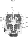
- FIG. 6 Another turbomolecular pump 300 is shown, which is basically similar to the turbomolecular pump 111 described above and in Fig. 1 to 5 shown (see especially Fig. 3 with Fig. 6 ). The above description of the turbomolecular pump 111 therefore also applies to the Turbomolecular pump 300, unless otherwise stated or shown.
- the turbomolecular pump 300 like the turbomolecular pump 111, comprises a rotor 302, which is supported on the high vacuum side by means of a magnetic bearing 304 and on the opposite side by means of a ball bearing 306.
- the turbomolecular pump 300 also comprises a turbomolecular region 310, which has four turbomolecular pump stages 312. Each of the turbomolecular pump stages 312 is assigned a respective rotor disk 314, which is attached to the rotor 302.
- a stator disk 316 is located between each of the rotor disks 314.
- the turbomolecular pump 300 Downstream of the turbomolecular region 310, the turbomolecular pump 300 has a transition region 320 and a pre-pumping region 330.
- the pre-pumping region 330 comprises a pre-pumping stage 332, which is designed as a Holweck pumping stage.
- the rotor 302 Due to the high speed of the rotor 302, which in turbomolecular pumps is usually well above 10,000 revolutions per minute, considerable heating occurs within the turbomolecular region 310 during operation of the turbomolecular pump 300. Due to the gas friction of the pump-active elements of the turbomolecular pump 300, for example the rotor disks 314 and the stator disks 316, the rotor 302 can heat up to 90°C and more, for example, particularly at high gas loads. This is due, among other things, to the fact that the stator disks 316 do not have sufficient thermal contact with a housing 340 of the turbomolecular pump 300 in order to transfer the amount of heat generated from the turbomolecular pump stages 312 to the housing 340.
- the rotor disks 314 are thermally very well insulated from the housing 340 due to the magnetic bearing of the rotor 302 on the high vacuum side of the turbomolecular pump 300, due to the ball bearing 306 and due to the high vacuum that exists in the turbomolecular region 310 when the turbomolecular pump 300 is operating. Due to this thermal insulation and due to the high speed of the rotor 302, heating of the rotor 302 during operation of the turbomolecular pump 300 cannot be prevented or reduced directly and with simple means.
- the turbomolecular pump 300 has a flow path 350 for a gas to be pumped, which Fig. 6 and 7 is indicated by the white arrows 350.
- the flow path 350 of the gas to be pumped is limited in sections by the pump-active elements of the turbomolecular pump stages 312 and the pre-pumping stage or Holweck pump stage 332.
- the pump-active elements i.e. the rotor disks 314 and the stator disks 316 as well as the pump-active elements of the Holweck pump stage 332, determine the geometric course of the flow path 350 in sections.
- the flow path 350 thus represents a volume within the turbomolecular pump 300 in which the gas to be pumped moves from the inlet of the turbomolecular pump 300 to its outlet.
- the flow path 350 is assigned a preferred direction for the movement of the gas to be pumped, this preferred direction running from the high vacuum side of the turbomolecular pump 300 to its outlet side.
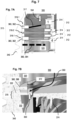
- the turbomolecular pump 300 has a cooling element 360 (cf. Fig. 7 ), which is arranged upstream of the pre-pumping stage or Holweck pumping stage 332 and projects into the flow path 350 of the turbomolecular pump 300.
- a cooling element 360 cf. Fig. 7
- Fig. 7A and 7B Several possibilities or embodiments for the arrangement and design of the cooling element 360 are shown.
- Fig. 7A the cooling element 360 is located either in the region 310 of the turbomolecular pumping stages 312 or in the transition region 320 immediately below the last turbomolecular pumping stage 312, ie downstream immediately adjacent to the last rotor disk 314.
- Fig. 7B shows an arrangement of the cooling element 360 directly in front of an inlet area 370 of the pre-pumping stage or Holweck pumping stage 332.
- Fig. 7A shows an enlarged section of the turbomolecular pump 300 from Fig. 6 which includes a portion of the turbomolecular region 310 and the transition region 320.
- the four respective rotor disks 314 of the turbomolecular pumping stages 312 are numbered 1 to 4.
- the cooling element 360 which is arranged in the upper part of Fig. 7A and designated 362, the cooling element 360, 362 forms part of one of the Fig. 6 shown stator disks 316 and thereby protrudes into the flow path 350.
- the cooling element 360, 362 is ring-shaped and completely surrounds the flow path 350 of the gas to be conveyed.
- the cooling element 360, 362 has a larger contact area with the housing 340 than another stator disk 316-2 without cooling element 360.
- the cooling element 360, 362 is therefore on the one hand in contact with a surface of the turbomolecular pump 300 and thus in thermal contact, which is almost at ambient temperature, ie at the temperature of the housing when the turbomolecular pump 300 is in operation.
- the cooling element 360, 362 is also in thermal contact with hot gas within the flow path 350 during operation, since it protrudes into it. This also applies to the embodiments of the cooling element 360 described below. Furthermore, the cooling element 360 can be designed as a cooling rib or cooling fin in order to improve the thermal contact with the hot gas.
- the cooling element 360, 362 forms a reinforced section of a stator disk 316-1. In comparison to the other stator disk 316-2 without cooling element 360, the cooling element 360 thus protrudes into the flow path 350 as a reinforced section in the outer region of the stator disk 316-1.
- the cooling element 360, 362 can be arranged in the first embodiment at different axial positions, ie in different pumping stages of the turbomolecular pump 300.
- a cooling element 360, 362 is arranged between the rotor disks 314 designated 1 and 2 and/or between the rotor disks 314 designated 3 and 4.
- an inclined stator blade 317 is schematically indicated for the stator disk 316-1 between the rotor disks 314 designated 1 and 2.
- the cooling element 360, 362 Due to its geometry and material, for example aluminum, the cooling element 360, 362 has improved thermal contact with the housing 340, i.e. compared to the stator disk 316-2 without a cooling element.
- the cooling element 360, 362 is thus designed to transfer a larger amount of heat to the housing 340 during a predetermined period of time than the respective pump-active elements of the turbomolecular pump stages 312, i.e. a larger amount of heat than the stator disks 316-2 without a cooling element.
- This also applies to the other embodiments of the cooling element 316, which are described below and designated 364 and 366, respectively.
- the cooling element 360 can form a spacer ring between at least two stator disks 316 of the turbomolecular pump stages 312. In this embodiment, the cooling element protrudes into the axial region of one of the rotor disks 314. flow path 350 and is thus located approximately at the same axial height as the corresponding rotor disk 314.
- the cooling element 360 which is arranged in the lower part of Fig. 7A As shown, the cooling element 360 is designed as a perforated diaphragm 364, which is arranged downstream of the pump-active elements 314, 316 of the turbomolecular pump stages 312. The perforated diaphragm 364 is thus already located in the transition region 320 between the turbomolecular region 310 and the pre-pumping region 330.
- the cooling element 360 is designed as an annular aperture 366, which is located in the transition region 320 immediately in front of the inlet region 370 of the pre-pumping stage or Holweck pumping stage 332.
- the inlet region 370 of the Holweck pumping stage 332 has a clear width 372.
- the clear width 372 designates the radial distance over which the inlet region 370 of the Holweck pumping stage is open in the radial direction.
- the clear width 372 thus defines an annular surface between the annular aperture 366 and a rotor element 374 of the Holweck pump stage 332. Within this annular surface, the inlet region 370 of the Holweck pump stage 332 is not covered by the cooling element 360 or the annular aperture 366 as long as the clear width 372 is greater than zero.
- cooling element 360 can be combined with one another in any way in the turbomolecular pump 300, ie one or more cooling elements 360 corresponding to the embodiments described above can be implemented in the turbomolecular pump 300. Alternatively, only a single cooling element 360 can be used in each case.
- Fig. 8 shows a diagram in which a measured rotor temperature in °C is plotted against the gas load in sccm (standard cubic centimeters per minute) at the inlet of the turbomolecular pump 300.
- the measurement curves of Fig. 8 were recorded for nitrogen as the gas to be pumped at a forevacuum pressure of 2 mbar.
- the turbomolecular pump 300 was operated at a rotation frequency of the rotor 302 (cf. Fig. 6 ) of 820 Hz.
- the clear width was 372 (cf. Fig. 7B ).
- the measurement curve 380 was recorded at a clear width 372 of 9.6 mm, which corresponds to a design of the turbomolecular pump 300 without the ring orifice 366.
- This design without the ring orifice 366 with the maximum clear width 372 serves as a reference for the measurements with different inner diameters of the ring orifice 366, in which the clear width 372 was successively reduced until it completely covered the inlet area 370 of the Holweck pump stage 332.
- the rotor temperature at the maximum clear width of 9.6 mm and a gas load of 150 sccm is approximately 75°C.
- the rotor temperature decreases as the gas load decreases, so that the rotor temperature at a gas load of approximately 20 sccm is only approximately 65°C.
- the turbomolecular pump 300 was provided with a cooling element 360 in the form of the ring orifice 366 (cf. Fig. 7B ), with an inner diameter of the ring aperture 366 such that the clearance 372 was 4 mm.
- the clearance was reduced by reducing the inner diameter of the ring aperture 366 to 2 mm and 0 mm respectively.
- the annular orifice 366 already completely covered the inlet area 370 of the Holweck pump stage 332 in the radial direction.
- the clear width 372 was -5 mm, so that the annular aperture 366 completely covered the inlet area 370 of the Holweck pump stage 332 and extended radially into the area of a rotor element 374 (cf. Fig. 7B ) of the Holweck pump stage 332.
- the inner diameter of the annular aperture 366 was smaller than the outer diameter of the rotor element 374 of the Holweck pump stage 332.
- the presence of the ring aperture 366 generally leads to a reduction in the rotor temperature over the entire measured range of the gas load. This is already apparent from curve 382 with a clear width 372 of 4 mm, which is below the reference curve 380 over the entire measuring range of the gas load. Reducing the clear width 372 to 2 mm (curve 284) leads to a further reduction in the rotor temperature over the entire measuring range, while a further reduction in the clear width 372 to 0 mm significantly reduces the rotor temperature again, so that with a gas load of 20 sccm a rotor temperature of just above 50°C is reached (cf. measuring curve 386). Further reducing the inner diameter of the cooling aperture 366 until it covers a clear width 372 of -5 mm ultimately only causes a reduction in the rotor temperature at gas loads significantly above 50 sccm (cf. measuring curve 388).
- the measurement curves 382 to 388 show, in comparison to the measurement curve 380, that the cooling element 360 in the form of the ring diaphragm 366 is able to control the rotor temperature during operation of the turbomolecular pump 300 This also applies to the other embodiments of the cooling element 360, which are described in connection with Fig. 7A described.
- a simultaneous measurement of the pumping speed of the turbomolecular pump 300 i.e. simultaneously with the recording of the measurement curves 380 to 388 of Fig. 8 , showed a negligible reduction in the suction capacity in the presence of the ring orifice 366, even at a clear width 372 of 0 mm (curve 386 of Fig. 8 ). Even with a clearance of -5 mm (curve 388 of Fig. 8 ) the suction capacity was reduced by about 10% only at a relatively high inlet pressure of 0.01 mbar.
- the embodiment with a clear width 372 of the ring orifice 366 of -5 mm (corresponding to the curve 388 of Fig.
Landscapes
- Engineering & Computer Science (AREA)
- Mechanical Engineering (AREA)
- General Engineering & Computer Science (AREA)
- Physics & Mathematics (AREA)
- Thermal Sciences (AREA)
- Non-Positive Displacement Air Blowers (AREA)
Abstract
Description
- Die Erfindung betrifft eine Turbomolekularpumpe mit einem Gehäuse, mehreren turbomolekularen Pumpstufen und mindestens einer Vorpumpstufe, die stromabwärts der turbomolekularen Pumpstufen angeordnet ist.
- Turbomolekularpumpen werden üblicherweise bei einer Rotordrehzahl betrieben, die in einem Bereich oberhalb von 10.000 Umdrehungen pro Minute liegt. Da pumpaktive Elemente einer Turbomolekularpumpe, d.h. deren Rotor und Stator, üblicherweise keinen guten Wärmekontakt mit einem Gehäuse der Turbomolekularpumpe aufweisen, tritt im Betrieb der Turbomolekularpumpe eine erhebliche Erwärmung des Rotors auf. Es werden Rotortemperaturen von 90°C und mehr erreicht. Eine permanent hohe Rotortemperatur kann zu Schäden innerhalb der Turbomolekularpumpe führen und dadurch deren Lebensdauer verkürzen.
- Eine Aufgabe der Erfindung besteht darin, eine Turbomolekularpumpe zu schaffen, die ein Mittel zur Verringerung der Temperatur des Rotors aufweist.
- Diese Aufgabe wird durch eine Turbomolekularpumpe mit den Merkmalen des Anspruchs 1 gelöst. Vorteilhafte Weiterbildungen der Erfindung sind in den Unteransprüchen, der Beschreibung und den Zeichnungen angegeben.
- Die Turbomolekularpumpe umfasst ein Gehäuse, mehrere turbomolekulare Pumpstufen, mindestens eine Vorpumpstufe, die stromabwärts der turbomolekularen Pumpstufen angeordnet ist. Die Turbomolekularpumpe weist ferner einen Strömungspfad eines zu fördernden Gases auf, der abschnittsweise durch pumpaktive Elemente der turbomolekularen Pumpstufen und der Vorpumpstufe festgelegt ist.
- Darüber hinaus umfasst die Turbomolekularpumpe ein Kühlungselement, das stromaufwärts der Vorpumpstufe in den Strömungspfad hineinragt. Das Kühlungselement ist ausgebildet, während einer vorbestimmten Zeitdauer eine größere Wärmemenge auf das Gehäuse der Turbomolekularpumpe zu übertragen als die jeweiligen pumpaktiven Elemente der turbomolekularen Pumpstufen.
- Der Strömungspfad des zu fördernden Gases durch die Turbomolekularpumpe hindurch, d.h. durch die mehreren turbomolekularen Pumpstufen, durch die mindestens eine Vorpumpstufe und durch Übergangsbereiche zwischen diesen, kann durch bestimmte Abmessungen der pumpaktiven Elemente geometrisch festgelegt sein, beispielsweise durch einen jeweiligen Innen- und Außendurchmesser für Schaufeln an Stator- bzw. Rotorscheiben, welche die pumpaktiven Elemente innerhalb der turbomolekularen Pumpstufen bilden können. Der Strömungspfad durch die Turbomolekularpumpe hindurch kann als ein Volumen mit einer Vorzugsrichtung für die Gasströmung des zu fördernden Gases definiert werden und ist somit mit dem inneren Volumen eines Rohres oder Schlauchs mit angegebener Strömungsrichtung vergleichbar. Anders ausgedrückt begrenzen die pumpaktiven Elemente der jeweiligen Pumpstufen der Turbomolekularpumpe den Strömungspfad des zu fördernden Gases in dem jeweiligen Abschnitt, in welchem sich das jeweilige pumpaktive Element dieser Pumpstufe befindet.
- Da das Kühlungselement während der vorbestimmten Zeitdauer eine größere Wärmemenge auf das Gehäuse überträgt als die jeweiligen pumpaktiven Elemente der turbomolekularen Pumpstufen, besteht für das Kühlungselement eine bessere thermische Ankopplung an das Gehäuse der Turbomolekularpumpe als für die pumpaktiven Elemente, insbesondere für die Statorscheiben, der jeweiligen turbomolekularen Pumpstufen. Die bessere thermische Ankopplung kann durch die Auswahl des Materials des Kühlungselements und durch dessen geometrische Ausgestaltung erreicht werden. Das Kühlungselement ist also derart beschaffen, dass es in derselben Zeitspanne eine größere Wärmemenge auf das Gehäuse übertragen kann als ein jeweiliges pumpaktives Element mit vergleichbaren Abmessungen.
- Das Kühlungselement kann während des Betriebs der Turbomolekularpumpe einerseits mit einer "kalten" Oberfläche der Turbomolekularpumpe, d.h. mit einer Oberfläche, welche die Betriebstemperatur an einer Außenseite des Gehäuses und somit nahezu Umgebungstemperatur aufweist und mit dem Gehäuse in Berührung steht, und andererseits mit einem heißen Gas in thermischem Kontakt stehen, das sich in dem Strömungspfad der Turbomolekularpumpe befindet.
- Da das Kühlungselement sozusagen als Hindernis in den Strömungspfad hineinragt, verjüngt das Kühlungselement den Strömungspfad in einem vordefinierten Abschnitt. Da das Kühlungselement stromaufwärts der Vorpumpstufe angeordnet ist, die beispielsweise mindestens eine Holweck-Pumpstufe und/oder mindestens eine Seitenkanal-Pumpstufe umfasst, verringert das Kühlungselement aufgrund des intensiven Wärmekontakts mit dem Gehäuse die Temperatur der Gasströmung innerhalb der turbomolekularen Pumpstufen. Dadurch wird die Temperatur der turbomolekularen Pumpstufen und insbesondere die Rotortemperatur verringert. Das Kühlungselement zeichnet sich ferner dadurch aus, dass für seine Implementierung innerhalb der Turbomolekularpumpe relativ geringfügige bauliche Veränderungen erforderlich sind. Das Kühlungselement kann beispielsweise dadurch implementiert werden, dass der Innendurchmesser bereits vorhandener Distanzelemente oder Ringblenden verringert wird.
- Gemäß einer Ausführungsform weist das Kühlungselement eine größere Kontaktfläche mit dem Gehäuse auf als ein jeweiliges der pumpaktiven Elemente der turbomolekularen Pumpstufen. Zusätzlich kann das Kühlungselement aus einem Material mit einer höheren Wärmeleitfähigkeit als die Wärmeleitfähigkeit des Materials der pumpaktiven Elemente hergestellt sein. Durch die größere Kontaktfläche und/oder das Material mit höherer Wärmeleitfähigkeit kann die Wärmeübertragung des Kühlungselements auf das Gehäuse innerhalb eines vorgegebenen Bauraums für das Kühlungselement optimiert werden.
- Gemäß einer weiteren Ausführungsform ist das Kühlungselement ringförmig ausgebildet, und es kann den Strömungspfad des zu fördernden Gases vollständig umgeben. Da der Strömungspfad somit vollständig von dem Kühlungselement umschlossen sein kann, kann der für das Kühlungselement vorhandene Bauraum optimal für die Wärmeübertragung von dem zu fördernden Gas über das Kühlungselement auf das Gehäuse der Turbomolekularpumpe ausgenutzt werden.
- Das Kühlungselement kann ferner zwei Halbringe oder Halbscheiben umfassen, um den Strömungspfad des zu fördernden Gases vollständig zu umschließen. Der Aufbau des Kühlungselements aus zwei Halbringen oder Halbscheiben kann die Herstellung und die Implementierung des Kühlungselements erleichtern.
- Die pumpaktiven Elemente der turbomolekularen Pumpstufen können Rotorscheiben mit einem vorbestimmten Außendurchmesser umfassen, und ein Innendurchmesser des Kühlungselements kann kleiner sein als der Außendurchmesser der Rotorscheiben. Die pumpaktiven Elemente der turbomolekularen Pumpstufen können außer den Rotorscheiben Statorscheiben umfassen, deren Geometrie den Strömungspfad des zu fördernden Gases ebenfalls festlegt. Da der Innendurchmesser des Kühlungselements kleiner als der Außendurchmesser der Rotorscheiben ist, ist durch den Innendurchmesser des Kühlungselements definiert festgelegt, wie weit dieses in den Strömungspfad hineinragt. Das Kühlungselement kann entweder zwischen den Rotor- und Statorscheiben, d.h. innerhalb der turbomolekularen Pumpstufen, oder in einem Übergangsbereich zu der Vorpumpstufe stromabwärts der letzten Rotor- oder Statorscheibe angeordnet sein.
- Gemäß einer weiteren Ausführungsform kann das Kühlungselement in einem Bereich der pumpaktiven Elemente der turbomolekularen Pumpstufen angeordnet sein. In diesem Fall kann das Kühlungselement beispielsweise die Temperatur eines Rotors der Turbomolekularpumpe aufgrund des geringen Abstands zwischen Kühlungselement und Rotor in besonderem Maß verringern.
- Das Kühlungselement kann bei einer Anordnung im Bereich der turbomolekularen Pumpstufe als Distanzelement zwischen zumindest zwei Statorscheiben der turbomolekularen Pumpstufen ausgebildet sein. Mit anderen Worten kann ein Distanzelement bezüglich seiner Geometrie und seines Materials derart ausgestaltet sein, dass es als Kühlungselement wirkt, das in den Strömungspfad der Turbomolekularpumpe hineinragt. Dies ermöglicht eine Implementierung des Kühlungselements mit geringem Aufwand, da lediglich ein bereits vorgesehenes Distanzelement durch das Kühlungselement zu ersetzten ist.
- Darüber hinaus kann das Kühlungselement einen Teil zumindest einer Statorscheibe der turbomolekularen Pumpstufen bilden. Eine solche Statorscheibe mit Kühlungselement kann beispielsweise einen verstärkten Abschnitt aufweisen, der in den Strömungspfad hineinragt und einen üblicherweise offenen Bereich innerhalb der Statorscheibe zumindest teilweise abdeckt. Hierbei kann das Kühlungselement wiederum mit relativ geringem Aufwand implementiert werden, da lediglich eine vorhandene Statorscheibe zu modifizieren ist.
- Ferner kann das Kühlungselement als eine Kühlrippe oder eine Kühlfinne ausgebildet sein. Eine solche Ausbildung des Kühlungselements kann den thermischen Kontakt zwischen dem heißen Gas, das in dem Strömungspfad vorhanden ist, und der Oberfläche des Kühlungselements verbessern bzw. optimieren.
- Außerdem kann das Kühlungselement als Lochblende ausgebildet sein, die zwischen zumindest zwei Statorscheiben der turbomolekularen Pumpstufen oder alternativ stromabwärts der pumpaktiven Elemente der turbomolekularen Pumpstufen angeordnet ist. Mittels einer solchen Lochblende kann der Wärmekontakt zwischen dem zu fördernden Gas und dem Gehäuse der Turbomolekularpumpe über das Kühlungselement maximiert werden. Öffnungen innerhalb der Lochblende können bei einer solchen Ausführungsform jedoch derart ausgestaltet sein, dass die Turbomolekularpumpe mittels der turbomolekularen Pumpstufen ein gewünschtes Saugvermögen erreicht, das durch eine bestimmte Anzahl von Litern des zu fördernden Gases pro Sekunde definiert ist.
- Gemäß einer weiteren Ausführungsform ist das Kühlungselement als eine Ringblende ausgebildet, die in einem Übergangsbereich zwischen einem Raumbereich, in dem sich die turbomolekularen Pumpstufen befinden, und der Vorpumpstufe angeordnet ist. Die Ringblende als Kühlungselement kann sich somit vor einem Einlassbereich der Vorpumpstufe für das zu fördernde Gas befinden. Der Einlassbereich der Vorpumpstufe kann mit einem Auslassbereich der turbomolekularen Pumpstufen derart in Verbindung stehen, dass sich der Übergangsbereich zwischen dem Auslassbereich der turbomolekularen Pumpstufen und dem Einlassbereich der Vorpumpstufe befindet. In dem Übergangsbereich bildet die Ringblende sozusagen eine Verjüngung, die den Einlassbereich der Vorpumpstufe zumindest teilweise überdeckt. Dadurch kann ein intensiver Wärmekontakt zwischen dem zu fördernden Gas und dem Gehäuse über die Ringblende hergestellt werden. Außerdem kann das Kühlungselement als Ringblende in dem Übergangsbereich auf einfachere Weise implementiert werden als beispielsweise als Kühlungselement zwischen Rotor- und Statorscheiben der turbomolekularen Pumpstufen.
- Die Ringblende kann einen offenen Einlassbereich der Vorpumpstufe zumindest teilweise überdecken. Bei einer solchen Ausführungsform kann somit eine positive lichte Weite innerhalb des Einlassbereichs der Vorpumpstufe bestehen bleiben, obwohl die Ringblende stromaufwärts der Vorpumpstufe installiert ist. Die Überdeckung durch die Ringblende bezieht sich auf eine radiale Richtung innerhalb der Turbomolekularpumpe, die rechtwinklig zu einer Drehachse eines Rotors der Turbomolekularpumpe verläuft. Die Drehachse des Rotors definiert wiederum eine axiale Richtung innerhalb der Turbomolekularpumpe.
- Die Ringblende kann ferner den offenen Einlassbereich der Vorpumpstufe in der radialen Richtung der Turbomolekularpumpe vollständig überdecken. Es hat sich gezeigt, dass die Temperatur des Rotors durch eine solche Ausgestaltung der Ringblende in besonderem Maß verringert werden kann. Obwohl die Ringblende den Einlassbereich in radialer Richtung vollständig überdeckt, ist der Einlassbereich der Vorpumpstufe in der axialen Richtung weiterhin offen, so dass das zu fördernde Gas mit einem ausreichenden Volumenstrom in Litern pro Sekunde in die Vorpumpstufe eintreten kann.
- Ferner kann die Ringblende einen Innendurchmesser aufweisen, der kleiner als ein Außendurchmesser eines Rotorelements der Vorpumpstufe ist. In diesem Fall weist die Ringblende in radialer Richtung eine sogenannte negative lichte Weite bezogen auf den Einlassbereich der Vorpumpstufe auf. Es hat sich gezeigt, dass sich die Temperatur des Rotors mit einer solchen Ausgestaltung am stärksten verringern lässt. In axialer Richtung weist der Einlassbereich der Vorpumpstufe jedoch wiederum eine geeignete Breite auf, um das Strömungsverhalten des zu fördernden Gases im Vergleich zu einer Turbomolekularpumpe ohne eine solche Ringblende nur unwesentlich zu beeinträchtigen und das gesamte Saugvermögen der Turbomolekularpumpe im Wesentlichen aufrechtzuerhalten.
- Das Kühlungselement kann aus Aluminium hergestellt sein und eine axiale Höhe in einem Bereich von 2 mm bis 3 mm aufweisen. Eine solche Ausgestaltung kann bei allen vorstehend beschriebenen Ausführungsformen verwendet werden. Ein Kühlungselement aus Aluminium und mit einer solchen Abmessung kann auf relativ einfache Weise hergestellt werden.
- Nachfolgend wird die Erfindung beispielhaft anhand vorteilhafter Ausführungsformen unter Bezugnahme auf die beigefügten Figuren beschrieben. Es zeigen, jeweils schematisch:
- Fig. 1
- eine perspektivische Ansicht einer Turbomolekularpumpe,
- Fig. 2
- eine Ansicht der Unterseite der Turbomolekularpumpe von
Fig. 1 , - Fig. 3
- einen Querschnitt der Turbomolekularpumpe längs der in
Fig. 2 gezeigten Schnittlinie A-A, - Fig. 4
- eine Querschnittsansicht der Turbomolekularpumpe längs der in
Fig. 2 gezeigten Schnittlinie B-B, - Fig. 5
- eine Querschnittsansicht der Turbomolekularpumpe längs der in
Fig. 2 gezeigten Schnittlinie C-C, - Fig. 6
- eine weitere Querschnittsansicht einer Turbomolekularpumpe,
- Fig. 7
- verschiedene Ausführungsformen für die Anordnung eines Kühlungselements in der Turbomolekularpumpe von
Fig. 6 und - Fig. 8
- ein Diagramm, das die Rotortemperatur in Abhängigkeit vom Gasfluss für verschiedene Innendurchmesser einer Ringblende im Strömungspfad der Turbomolekularpumpe von
Fig. 6 und7 zeigt. - Die in
Fig. 1 gezeigte Turbomolekularpumpe 111 umfasst einen von einem Einlassflansch 113 umgebenen Pumpeneinlass 115, an welchen in an sich bekannter Weise ein nicht dargestellter Rezipient angeschlossen werden kann. Das Gas aus dem Rezipienten kann über den Pumpeneinlass 115 aus dem Rezipienten gesaugt und durch die Pumpe hindurch zu einem Pumpenauslass 117 gefördert werden, an den eine Vorvakuumpumpe, wie etwa eine Drehschieberpumpe, angeschlossen sein kann. - Der Einlassflansch 113 bildet bei der Ausrichtung der Vakuumpumpe gemäß
Fig. 1 das obere Ende des Gehäuses 119 der Vakuumpumpe 111. Das Gehäuse 119 umfasst ein Unterteil 121, an welchem seitlich ein Elektronikgehäuse 123 angeordnet ist. In dem Elektronikgehäuse 123 sind elektrische und/oder elektronische Komponenten der Vakuumpumpe 111 untergebracht, z.B. zum Betreiben eines in der Vakuumpumpe angeordneten Elektromotors 125 (vgl. auchFig. 3 ). Am Elektronikgehäuse 123 sind mehrere Anschlüsse 127 für Zubehör vorgesehen. Außerdem sind eine Datenschnittstelle 129, z.B. gemäß dem RS485-Standard, und ein Stromversorgungsanschluss 131 am Elektronikgehäuse 123 angeordnet. - Es existieren auch Turbomolekularpumpen, die kein derartiges angebrachtes Elektronikgehäuse aufweisen, sondern an eine externe Antriebselektronik angeschlossen werden.
- Am Gehäuse 119 der Turbomolekularpumpe 111 ist ein Fluteinlass 133, insbesondere in Form eines Flutventils, vorgesehen, über den die Vakuumpumpe 111 geflutet werden kann. Im Bereich des Unterteils 121 ist ferner noch ein Sperrgasanschluss 135, der auch als Spülgasanschluss bezeichnet wird, angeordnet, über welchen Spülgas zum Schutz des Elektromotors 125 (siehe z.B.
Fig. 3 ) vor dem von der Pumpe geförderten Gas in den Motorraum 137, in welchem der Elektromotor 125 in der Vakuumpumpe 111 untergebracht ist, eingelassen werden kann. Im Unterteil 121 sind ferner noch zwei Kühlmittelanschlüsse 139 angeordnet, wobei einer der Kühlmittelanschlüsse als Einlass und der andere Kühlmittelanschluss als Auslass für Kühlmittel vorgesehen ist, das zu Kühlzwecken in die Vakuumpumpe geleitet werden kann. Andere existierende Turbomolekularvakuumpumpen (nicht dargestellt) werden ausschließlich mit Luftkühlung betrieben. - Die untere Seite 141 der Vakuumpumpe kann als Standfläche dienen, sodass die Vakuumpumpe 111 auf der Unterseite 141 stehend betrieben werden kann. Die Vakuumpumpe 111 kann aber auch über den Einlassflansch 113 an einem Rezipienten befestigt werden und somit gewissermaßen hängend betrieben werden. Außerdem kann die Vakuumpumpe 111 so gestaltet sein, dass sie auch in Betrieb genommen werden kann, wenn sie auf andere Weise ausgerichtet ist als in
Fig. 1 gezeigt ist. Es lassen sich auch Ausführungsformen der Vakuumpumpe realisieren, bei der die Unterseite 141 nicht nach unten, sondern zur Seite gewandt oder nach oben gerichtet angeordnet werden kann. Grundsätzlich sind dabei beliebige Winkel möglich. - Andere existierende Turbomolekularvakuumpumpen (nicht dargestellt), die insbesondere größer sind als die hier dargestellte Pumpe, können nicht stehend betrieben werden.
- An der Unterseite 141, die in
Fig. 2 dargestellt ist, sind noch diverse Schrauben 143 angeordnet, mittels denen hier nicht weiter spezifizierte Bauteile der Vakuumpumpe aneinander befestigt sind. Beispielsweise ist ein Lagerdeckel 145 an der Unterseite 141 befestigt. - An der Unterseite 141 sind außerdem Befestigungsbohrungen 147 angeordnet, über welche die Pumpe 111 beispielsweise an einer Auflagefläche befestigt werden kann. Dies ist bei anderen existierenden Turbomolekularvakuumpumpen (nicht dargestellt), die insbesondere größer sind als die hier dargestellte Pumpe, nicht möglich.
- In den
Figuren 2 bis 5 ist eine Kühlmittelleitung 148 dargestellt, in welcher das über die Kühlmittelanschlüsse 139 ein- und ausgeleitete Kühlmittel zirkulieren kann. - Wie die Schnittdarstellungen der
Figuren 3 bis 5 zeigen, umfasst die Vakuumpumpe mehrere Prozessgaspumpstufen zur Förderung des an dem Pumpeneinlass 115 anstehenden Prozessgases zu dem Pumpenauslass 117. - In dem Gehäuse 119 ist ein Rotor 149 angeordnet, der eine um eine Rotationsachse 151 drehbare Rotorwelle 153 aufweist.
- Die Turbomolekularpumpe 111 umfasst mehrere pumpwirksam miteinander in Serie geschaltete turbomolekulare Pumpstufen mit mehreren an der Rotorwelle 153 befestigten radialen Rotorscheiben 155 und zwischen den Rotorscheiben 155 angeordneten und in dem Gehäuse 119 festgelegten Statorscheiben 157. Dabei bilden eine Rotorscheibe 155 und eine benachbarte Statorscheibe 157 jeweils eine turbomolekulare Pumpstufe. Die Statorscheiben 157 sind durch Abstandsringe 159 in einem gewünschten axialen Abstand zueinander gehalten.
- Die Vakuumpumpe umfasst außerdem in radialer Richtung ineinander angeordnete und pumpwirksam miteinander in Serie geschaltete Holweck-Pumpstufen. Es existieren andere Turbomolekularvakuumpumpen (nicht dargestellt), die keine Holweck-Pumpstufen aufweisen.
- Der Rotor der Holweck-Pumpstufen umfasst eine an der Rotorwelle 153 angeordnete Rotornabe 161 und zwei an der Rotornabe 161 befestigte und von dieser getragene zylindermantelförmige Holweck-Rotorhülsen 163, 165, die koaxial zur Rotationsachse 151 orientiert und in radialer Richtung ineinander geschachtelt sind. Ferner sind zwei zylindermantelförmige Holweck-Statorhülsen 167, 169 vorgesehen, die ebenfalls koaxial zu der Rotationsachse 151 orientiert und in radialer Richtung gesehen ineinander geschachtelt sind.
- Die pumpaktiven Oberflächen der Holweck-Pumpstufen sind durch die Mantelflächen, also durch die radialen Innen- und/oder Außenflächen, der Holweck-Rotorhülsen 163, 165 und der Holweck-Statorhülsen 167, 169 gebildet. Die radiale Innenfläche der äußeren Holweck-Statorhülse 167 liegt der radialen Außenfläche der äußeren Holweck-Rotorhülse 163 unter Ausbildung eines radialen Holweck-Spalts 171 gegenüber und bildet mit dieser die der Turbomolekularpumpen nachfolgende erste Holweck-Pumpstufe. Die radiale Innenfläche der äußeren Holweck-Rotorhülse 163 steht der radialen Außenfläche der inneren Holweck-Statorhülse 169 unter Ausbildung eines radialen Holweck-Spalts 173 gegenüber und bildet mit dieser eine zweite Holweck-Pumpstufe. Die radiale Innenfläche der inneren Holweck-Statorhülse 169 liegt der radialen Außenfläche der inneren Holweck-Rotorhülse 165 unter Ausbildung eines radialen Holweck-Spalts 175 gegenüber und bildet mit dieser die dritte Holweck-Pumpstufe.
- Am unteren Ende der Holweck-Rotorhülse 163 kann ein radial verlaufender Kanal vorgesehen sein, über den der radial außenliegende Holweck-Spalt 171 mit dem mittleren Holweck-Spalt 173 verbunden ist. Außerdem kann am oberen Ende der inneren Holweck-Statorhülse 169 ein radial verlaufender Kanal vorgesehen sein, über den der mittlere Holweck-Spalt 173 mit dem radial innenliegenden Holweck-Spalt 175 verbunden ist. Dadurch werden die ineinander geschachtelten Holweck-Pumpstufen in Serie miteinander geschaltet. Am unteren Ende der radial innenliegenden Holweck-Rotorhülse 165 kann ferner ein Verbindungskanal 179 zum Auslass 117 vorgesehen sein.
- Die vorstehend genannten pumpaktiven Oberflächen der Holweck-Statorhülsen 167, 169 weisen jeweils mehrere spiralförmig um die Rotationsachse 151 herum in axialer Richtung verlaufende Holweck-Nuten auf, während die gegenüberliegenden Mantelflächen der Holweck-Rotorhülsen 163, 165 glatt ausgebildet sind und das Gas zum Betrieb der Vakuumpumpe 111 in den Holweck-Nuten vorantreiben.
- Zur drehbaren Lagerung der Rotorwelle 153 sind ein Wälzlager 181 im Bereich des Pumpenauslasses 117 und ein Permanentmagnetlager 183 im Bereich des Pumpeneinlasses 115 vorgesehen.
- Im Bereich des Wälzlagers 181 ist an der Rotorwelle 153 eine konische Spritzmutter 185 mit einem zu dem Wälzlager 181 hin zunehmenden Außendurchmesser vorgesehen. Die Spritzmutter 185 steht mit mindestens einem Abstreifer eines Betriebsmittelspeichers in gleitendem Kontakt. Bei anderen existierenden Turbomolekularvakuumpumpen (nicht dargestellt) kann anstelle einer Spritzmutter eine Spritzschraube vorgesehen sein. Da somit unterschiedliche Ausführungen möglich sind, wird in diesem Zusammenhang auch der Begriff "Spritzspitze" verwendet.
- Der Betriebsmittelspeicher umfasst mehrere aufeinander gestapelte saugfähige Scheiben 187, die mit einem Betriebsmittel für das Wälzlager 181, z.B. mit einem Schmiermittel, getränkt sind.
- Im Betrieb der Vakuumpumpe 111 wird das Betriebsmittel durch kapillare Wirkung von dem Betriebsmittelspeicher über den Abstreifer auf die rotierende Spritzmutter 185 übertragen und in Folge der Zentrifugalkraft entlang der Spritzmutter 185 in Richtung des größer werdenden Außendurchmessers der Spritzmutter 185 zu dem Wälzlager 181 hin gefördert, wo es z.B. eine schmierende Funktion erfüllt. Das Wälzlager 181 und der Betriebsmittelspeicher sind durch einen wannenförmigen Einsatz 189 und den Lagerdeckel 145 in der Vakuumpumpe eingefasst.
- Das Permanentmagnetlager 183 umfasst eine rotorseitige Lagerhälfte 191 und eine statorseitige Lagerhälfte 193, welche jeweils einen Ringstapel aus mehreren in axialer Richtung aufeinander gestapelten permanentmagnetischen Ringen 195, 197 umfassen. Die Ringmagnete 195, 197 liegen einander unter Ausbildung eines radialen Lagerspalts 199 gegenüber, wobei die rotorseitigen Ringmagnete 195 radial außen und die statorseitigen Ringmagnete 197 radial innen angeordnet sind.
- Das in dem Lagerspalt 199 vorhandene magnetische Feld ruft magnetische Absto-ßungskräfte zwischen den Ringmagneten 195, 197 hervor, welche eine radiale Lagerung der Rotorwelle 153 bewirken. Die rotorseitigen Ringmagnete 195 sind von einem Trägerabschnitt 201 der Rotorwelle 153 getragen, welcher die Ringmagnete 195 radial außenseitig umgibt. Die statorseitigen Ringmagnete 197 sind von einem statorseitigen Trägerabschnitt 203 getragen, welcher sich durch die Ringmagnete 197 hindurch erstreckt und an radialen Streben 205 des Gehäuses 119 aufgehängt ist. Parallel zu der Rotationsachse 151 sind die rotorseitigen Ringmagnete 195 durch ein mit dem Trägerabschnitt 201 gekoppeltes Deckelelement 207 festgelegt. Die statorseitigen Ringmagnete 197 sind parallel zu der Rotationsachse 151 in der einen Richtung durch einen mit dem Trägerabschnitt 203 verbundenen Befestigungsring 209 sowie einen mit dem Trägerabschnitt 203 verbundenen Befestigungsring 211 festgelegt. Zwischen dem Befestigungsring 211 und den Ringmagneten 197 kann außerdem eine Tellerfeder 213 vorgesehen sein.
- Innerhalb des Magnetlagers ist ein Not- bzw. Fanglager 215 vorgesehen, welches im normalen Betrieb der Vakuumpumpe 111 ohne Berührung leer läuft und erst bei einer übermäßigen radialen Auslenkung des Rotors 149 relativ zu dem Stator in Eingriff gelangt, um einen radialen Anschlag für den Rotor 149 zu bilden, damit eine Kollision der rotorseitigen Strukturen mit den statorseitigen Strukturen verhindert wird. Das Fanglager 215 ist als ungeschmiertes Wälzlager ausgebildet und bildet mit dem Rotor 149 und/oder dem Stator einen radialen Spalt, welcher bewirkt, dass das Fanglager 215 im normalen Pumpbetrieb außer Eingriff ist. Die radiale Auslenkung, bei der das Fanglager 215 in Eingriff gelangt, ist groß genug bemessen, sodass das Fanglager 215 im normalen Betrieb der Vakuumpumpe nicht in Eingriff gelangt, und gleichzeitig klein genug, sodass eine Kollision der rotorseitigen Strukturen mit den statorseitigen Strukturen unter allen Umständen verhindert wird.
- Die Vakuumpumpe 111 umfasst den Elektromotor 125 zum drehenden Antreiben des Rotors 149. Der Anker des Elektromotors 125 ist durch den Rotor 149 gebildet, dessen Rotorwelle 153 sich durch den Motorstator 217 hindurch erstreckt. Auf den sich durch den Motorstator 217 hindurch erstreckenden Abschnitt der Rotorwelle 153 kann radial außenseitig oder eingebettet eine Permanentmagnetanordnung angeordnet sein. Zwischen dem Motorstator 217 und dem sich durch den Motorstator 217 hindurch erstreckenden Abschnitt des Rotors 149 ist ein Zwischenraum 219 angeordnet, welcher einen radialen Motorspalt umfasst, über den sich der Motorstator 217 und die Permanentmagnetanordnung zur Übertragung des Antriebsmoments magnetisch beeinflussen können.
- Der Motorstator 217 ist in dem Gehäuse innerhalb des für den Elektromotor 125 vorgesehenen Motorraums 137 festgelegt. Über den Sperrgasanschluss 135 kann ein Sperrgas, das auch als Spülgas bezeichnet wird, und bei dem es sich beispielsweise um Luft oder um Stickstoff handeln kann, in den Motorraum 137 gelangen. Über das Sperrgas kann der Elektromotor 125 vor Prozessgas, z.B. vor korrosiv wirkenden Anteilen des Prozessgases, geschützt werden. Der Motorraum 137 kann auch über den Pumpenauslass 117 evakuiert werden, d.h. im Motorraum 137 herrscht zumindest annäherungsweise der von der am Pumpenauslass 117 angeschlossenen Vorvakuumpumpe bewirkte Vakuumdruck.
- Zwischen der Rotornabe 161 und einer den Motorraum 137 begrenzenden Wandung 221 kann außerdem eine sog. und an sich bekannte Labyrinthdichtung 223 vorgesehen sein, insbesondere um eine bessere Abdichtung des Motorraums 217 gegenüber den radial außerhalb liegenden Holweck-Pumpstufen zu erreichen.
- In
Fig. 6 ist eine weitere Turbomolekularpumpe 300 dargestellt, die der Turbomolekularpumpe 111 grundsätzlich ähnlich ist, welche vorstehend beschrieben und inFig. 1 bis 5 gezeigt (vgl. insbesondereFig. 3 mitFig. 6 ). Die vorstehende Beschreibung der Turbomolekularpumpe 111 gilt daher sinngemäß auch für die Turbomolekularpumpe 300, solange nichts Gegenteiliges beschrieben oder dargestellt ist. - Die Turbomolekularpumpe 300 umfasst ebenso wie die Turbomolekularpumpe 111 einen Rotor 302, der auf der Hochvakuumseite mittels eines Magnetlagers 304 und auf der entgegengesetzten Seite mittels eines Kugellagers 306 gelagert ist. Ferner umfasst die Turbomolekularpumpe 300 einen turbomolekularen Bereich 310, der vier turbomolekularen Pumpstufen 312 aufweist. Jeder der turbomolekularen Pumpstufen 312 ist eine jeweilige Rotorscheibe 314 zugeordnet, die an dem Rotor 302 angebracht ist. Zwischen den Rotorscheiben 314 befindet sich jeweils eine Statorscheibe 316.
- Stromabwärts des turbomolekularen Bereichs 310 weist die Turbomolekularpumpe 300 einen Übergangsbereich 320 und einen Vorpumpenbereich 330 auf. Der Vorpumpenbereich 330 umfasst eine Vorpumpstufe 332, die als Holweck-Pumpstufe ausgebildet ist.
- Aufgrund der hohen Drehzahl des Rotors 302, die bei Turbomolekularpumpen üblicherweise deutlich oberhalb von 10.000 Umdrehungen pro Minute liegt, tritt im Betrieb der Turbomolekularpumpe 300 eine erhebliche Erwärmung innerhalb des turbomolekularen Bereichs 310 auf. Aufgrund der Gasreibung der pumpaktiven Elemente der Turbomolekularpumpe 300, beispielsweise der Rotorscheiben 314 und der Statorscheiben 316, kann sich der Rotor 302 insbesondere bei hohen Gaslasten beispielsweise auf 90°C und mehr erwärmen. Dies ist unter anderem dadurch bedingt, dass die Statorscheiben 316 keinen ausreichenden Wärmekontakt mit einem Gehäuse 340 der Turbomolekularpumpe 300 aufweisen, um die anfallende Wärmemenge von den turbomolekularen Pumpstufen 312 auf das Gehäuse 340 zu übertragen.
- Die Rotorscheiben 314 sind aufgrund der Magnetlagerung des Rotors 302 auf der Hochvakuumseite der Turbomolekularpumpe 300, aufgrund des Kugellagers 306 und aufgrund des Hochvakuums, das im Betrieb der Turbomolekularpumpe 300 im turbomolekularen Bereich 310 vorliegt, wärmetechnisch sehr gut gegenüber dem Gehäuse 340 isoliert. Aufgrund dieser Wärmeisolierung und wegen der hohen Drehzahl des Rotors 302 kann eine Erwärmung des Rotors 302 während des Betriebs der Turbomolekularpumpe 300 nicht direkt und mit einfachen Mitteln verhindert bzw. verringert werden.
- Prinzipiell weist die Turbomolekularpumpe 300 einen Strömungspfad 350 für ein zu förderndes Gas auf, der in
Fig. 6 und7 durch die weißen Pfeile 350 angedeutet ist. Der Strömungspfad 350 des zu fördernden Gases ist abschnittsweise durch die pumpaktiven Elemente der turbomolekularen Pumpstufen 312 und der Vorpumpstufe bzw. Holweck-Pumpstufe 332 begrenzt. Mit anderen Worten legen die pumpaktiven Elemente, d.h. die Rotorscheiben 314 und die Statorscheiben 316 sowie die pumpaktiven Elemente der Holweck-Pumpstufe 332, abschnittsweise den geometrischen Verlauf des Strömungspfades 350 fest. Der Strömungspfad 350 repräsentiert somit ein Volumen innerhalb der Turbomolekularpumpe 300, in welchem sich das zu fördernde Gas vom Einlass der Turbomolekularpumpe 300 bis zu deren Auslass bewegt. Zusätzlich ist dem Strömungspfad 350 eine Vorzugsrichtung für die Bewegung des zu fördernden Gases zugeordnet, wobei diese Vorzugsrichtung von der Hochvakuumseite der Turbomolekularpumpe 300 bis zu deren Auslassseite verläuft. - Um die Rotortemperatur während des Betriebs der Turbomolekularpumpe 300 zu verringern, weist die Turbomolekularpumpe 300 ein Kühlungselement 360 auf (vgl.
Fig. 7 ), das stromaufwärts der Vorpumpstufe bzw. Holweck-Pumpstufe 332 angeordnet ist und in den Strömungspfad 350 der Turbomolekularpumpe 300 hineinragt. InFig. 7A und 7B sind mehrere Möglichkeiten bzw. Ausführungsformen für die Anordnung und Ausgestaltung des Kühlungselements 360 dargestellt. - In
Fig. 7A befindet sich das Kühlungselement 360 entweder im Bereich 310 der turbomolekularen Pumpstufen 312 oder im Übergangsbereich 320 unmittelbar unterhalb der letzten turbomolekularen Pumpstufe 312, d.h. stromabwärts unmittelbar anschließend an die letzte Rotorscheibe 314.Fig. 7B zeigt hingegen eine Anordnung des Kühlungselements 360 direkt vor einem Einlassbereich 370 der Vorpumpstufe bzw. Holweck-Pumpstufe 332. -
Fig. 7A zeigt einen vergrößerten Ausschnitt der Turbomolekularpumpe 300 vonFig. 6 , der einen Abschnitt des turbomolekularen Bereichs 310 und des Übergangsbereichs 320 umfasst. Die vier jeweiligen Rotorscheiben 314 der turbomolekularen Pumpstufen 312 sind mit den Ziffern 1 bis 4 nummeriert. - Bei einer ersten Ausführungsform des Kühlungselements 360, die im oberen Teil von
Fig. 7A dargestellt und mit 362 bezeichnet ist, bildet das Kühlungselement 360, 362 einen Teil einer der inFig. 6 gezeigten Statorscheiben 316 und ragt dadurch in den Strömungspfad 350 hinein. Das Kühlungselement 360, 362 ist ringförmig ausgebildet, und es umgibt den Strömungspfad 350 des zu fördernden Gases vollständig. Darüber hinaus weist das Kühlungselement 360, 362 eine größere Kontaktfläche mit dem Gehäuse 340 auf als eine weitere Statorscheibe 316-2 ohne Kühlungselement 360. Das Kühlungselement 360, 362 steht also einerseits mit einer Oberfläche der Turbomolekularpumpe 300 in Berührung und somit in thermischem Kontakt, die sich nahezu auf Umgebungstemperatur befindet, d.h. auf der Temperatur des Gehäuses im Betrieb der Turbomolekularpumpe 300. Andererseits steht das Kühlungselement 360, 362 während des Betriebs auch mit heißem Gas innerhalb des Strömungspfades 350 in thermischem Kontakt, da es in diesen hineinragt. Dies gilt ebenso für die nachstehend beschriebenen Ausführungsformen des Kühlungselements 360. Ferner kann das Kühlungselement 360 als Kühlrippe oder Kühlfinne ausgebildet sein, um den thermischen Kontakt mit dem heißen Gas zu verbessern. - Bei der ersten Ausführungsform des Kühlungselements 360, 362 bildet das Kühlungselement 360, 362 einen verstärkten Abschnitt einer Statorscheibe 316-1. Im Vergleich zu der weiteren Statorscheibe 316-2 ohne Kühlungselement 360 ragt das Kühlungselement 360 somit als verstärkter Abschnitt im Außenbereich der Statorscheibe 316-1 in den Strömungspfad 350 hinein. Das Kühlungselement 360, 362 kann bei der ersten Ausführungsform an verschiedenen axialen Positionen, d.h. in verschiedenen Pumpstufen des Turbomolekularpumpe 300 angeordnet sein. Im Beispiel von
Fig. 7A ist jeweils ein Kühlungselement 360, 362 zwischen den mit 1 und 2 bezeichneten Rotorscheiben 314 und/oder zwischen den mit 3 und 4 bezeichneten Rotorscheiben 314 angeordnet. Zur Veranschaulichung ist für die Statorscheibe 316-1 zwischen den mit 1 und 2 bezeichneten Rotorscheiben 314 eine schräg stehende Statorschaufel 317 schematisch angedeutet. - Aufgrund seiner Geometrie und seines Materials, beispielsweise Aluminium, verfügt das Kühlungselement 360, 362 über einen verbesserten Wärmekontakt mit dem Gehäuse 340, d.h. im Vergleich zu der Statorscheibe 316-2 ohne Kühlungselement. Das Kühlungselement 360, 362 ist dadurch ausgebildet, während einer vorbestimmten Zeitdauer eine größere Wärmemenge auf das Gehäuse 340 zu übertragen als die jeweiligen pumpaktiven Elemente der turbomolekularen Pumpstufen 312, d.h. eine größere Wärmemenge als die Statorscheiben 316-2 ohne Kühlungselement. Dies gilt ebenso für die weiteren Ausführungsformen des Kühlungselements 316, die nachstehend beschrieben und mit 364 bzw. 366 bezeichnet sind.
- Bei einer nicht dargestellten weiteren Ausführungsform kann das Kühlungselement 360 einen Distanzring zwischen zumindest zwei Statorscheiben 316 der turbomolekularen Pumpstufen 312 bilden. Das Kühlungselement ragt bei dieser Ausführungsform in dem axialen Bereich einer der Rotorscheiben 314 in den Strömungspfad 350 hinein und befindet sich somit etwa auf gleicher axialer Höhe wie die entsprechende Rotorscheibe 314.
- Bei einer weiteren Ausführungsform des Kühlungselements 360, die im unteren Teil von
Fig. 7A dargestellt ist, ist das Kühlungselement 360 als Lochblende 364 ausgebildet, die stromabwärts der pumpaktiven Elemente 314, 316 der turbomolekularen Pumpstufen 312 angeordnet ist. Die Lochblende 364 befindet sich somit bereits im Übergangsbereich 320 zwischen dem turbomolekularen Bereich 310 und dem Vorpumpenbereich 330. - Bei der in
Fig. 7B dargestellten Ausführungsform ist das Kühlungselement 360 hingegen als eine Ringblende 366 ausgebildet, die sich im Übergangsbereich 320 unmittelbar vor dem Einlassbereich 370 der Vorpumpstufe bzw. Holweck-Pumpstufe 332 befindet. In einer radialen Richtung, die rechtwinklig zu einer axialen Richtung verläuft, die durch die Drehachse des Rotors 302 definiert ist, weist der Einlassbereich 370 der Holweck-Pumpstufe 332 eine lichte Weite 372 auf. Die lichte Weite 372 bezeichnet diejenige radiale Distanz, über die der Einlassbereich 370 der Holweck-Pumpstufe in der radialen Richtung offen ist. Entlang der Drehachse des Rotors 302 gesehen definiert die lichte Weite 372 somit eine Ringfläche zwischen der Ringblende 366 und einem Rotorelement 374 der Holweck-Pumpstufe 332. Innerhalb dieser Ringfläche erfolgt keine Überdeckung des Einlassbereichs 370 der Holweck-Pumpstufe 332 durch das Kühlungselement 360 bzw. die Ringblende 366, solange die lichte Weite 372 größer als Null ist. - Die vorstehend beschriebenen Ausführungsformen des Kühlungselements 360 können in der Turbomolekularpumpe 300 beliebig miteinander kombiniert werden, d.h. es können ein oder mehrere Kühlungselemente 360 entsprechend den vorstehend beschriebenen Ausführungsformen in der Turbomolekularpumpe 300 implementiert sein. Alternativ kann jeweils nur ein einziges Kühlungselement 360 verwendet werden.
-
Fig. 8 zeigt ein Diagramm, in dem eine gemessene Rotortemperatur in °C über der am Einlass der Turbomolekularpumpe 300 anfallenden Gaslast in sccm (Standardkubikzentimeter pro Minute) aufgetragen ist. Die Messkurven vonFig. 8 wurden für Stickstoff als zu förderndes Gas bei einem Vorvakuumdruck von 2 mbar erfasst. Ferner wurde die Turbomolekularpumpe 300 bei einer Drehfrequenz des Rotors 302 (vgl.Fig. 6 ) von 820 Hz betrieben. - Bei den verschiedenen Messkurven 380 bis 388, die in
Fig. 8 dargestellt sind, wurde die lichte Weite 372 (vgl.Fig. 7B ) variiert. Die Messkurve 380 wurde bei einer lichten Weite 372 von 9,6 mm erfasst, die einer Ausgestaltung der Turbomolekularpumpe 300 ohne die Ringblende 366 entspricht. Diese Ausgestaltung ohne die Ringblende 366 mit der maximalen lichten Weite 372 dient als Referenz für die Messungen mit jeweils unterschiedlichen Innendurchmessern der Ringblende 366, bei denen die lichte Weite 372 sukzessive bis zu einer vollständigen Überdeckung des Einlassbereichs 370 der Holweck-Pumpstufe 332 verringert wurde. - Wie anhand der Messkurve 380 zu erkennen ist, liegt die Rotortemperatur bei der maximalen lichten Weite von 9,6 mm und einer Gaslast von 150 sccm bei etwa 75°C. Während des Betriebs der Turbomolekularpumpe 300 nimmt die Rotortemperatur mit sinkender Gaslast ab, so dass die Rotortemperatur bei einer Gaslast von etwa 20 sccm nur noch etwa 65°C beträgt.
- Für die Messkurve 382 wurde die Turbomolekularpumpe 300 mit einem Kühlungselement 360 in der Form der Ringblende 366 versehen (vgl.
Fig. 7B ), und zwar mit einem solchen Innendurchmesser der Ringblende 366, dass die lichte Weite 372 4 mm betrug. Für die weiteren Messkurven 384 und 386 wurde die lichte Weite durch eine jeweilige Verkleinerung des Innendurchmessers der Ringblende 366 auf 2 mm bzw. 0 mm verringert. Bei der Ausführungsform für die Messkurve 386 überdeckte die Ringblende 366 den Einlassbereich 370 der Holweck-Pumpstufe 332 bereits vollständig in radialer Richtung. - Bei der Ausführungsform für die Messkurve 388 betrug die lichte Weite 372 hingegen -5 mm, so dass die Ringblende 366 den Einlassbereich 370 der Holweck-Pumpstufe 332 vollständig überdeckte und in radialer Richtung in den Bereich eines Rotorelements 374 (vgl.
Fig. 7B ) der Holweck-Pumpstufe 332 hineinragte. Mit anderen Worten war bei der Ausführungsform für die Messkurve 388 der Innendurchmesser der Ringblende 366 kleiner als der Außendurchmesser des Rotorelements 374 der Holweck-Pumpstufe 332. - Wie anhand der Messkurven 382 bis 388 von
Fig. 8 zu erkennen ist, führt das Vorhandensein der Ringblende 366 generell zu einer Verringerung der Rotortemperatur über den gesamten erfassten Bereich der Gaslast. Dies ist bereits anhand der Kurve 382 bei einer lichten Weite 372 von 4 mm erkennbar, die im gesamten Messbereich der Gaslast unterhalb der Referenzkurve 380 liegt. Eine Verringerung der lichten Weite 372 auf 2 mm (Kurve 284) führt zu einer weiteren Verringerung der Rotortemperatur über den gesamten Messbereich, während eine weitere Verringerung der lichten Weite 372 auf 0 mm die Rotortemperatur nochmals deutlich verringert, so dass bei einer Gaslast von 20 sccm eine Rotortemperatur knapp oberhalb von 50°C erreicht wird (vgl. die Messkurve 386). Die weitere Verringerung des Innendurchmessers der Kühlblende 366 bis zu einer Überdeckung mit einer lichten Weite 372 von -5 mm bewirkt schließlich nur noch eine Verringerung der Rotortemperatur bei Gaslasten deutlich oberhalb von 50 sccm (vgl. die Messkurve 388). - Insgesamt zeigen die Messkurven 382 bis 388 im Vergleich zu der Messkurve 380, dass das Kühlungselement 360 in der Form der Ringblende 366 in der Lage ist, die Rotortemperatur während des Betriebs der Turbomolekularpumpe 300 erheblich zu verringern. Dies gilt ebenso für die weiteren Ausführungsformen des Kühlungselements 360, die im Zusammenhang mit
Fig. 7A beschrieben sind. - Eine gleichzeitige Messung des Saugvermögens der Turbomolekularpumpe 300, d.h. gleichzeitig mit der Erfassung der Messkurven 380 bis 388 von
Fig. 8 , zeigte eine vernachlässigbare Verringerung des Saugvermögens bei Vorhandensein der Ringblende 366, und zwar sogar bei einer lichten Weite 372 von 0 mm (Kurve 386 vonFig. 8 ). Auch bei einer lichten Weite von -5 mm (Kurve 388 vonFig. 8 ) war das Saugvermögen lediglich bei einem relativ hohen Einlassdruck von 0,01 mbar um etwa 10% verringert. Gleichzeitig zeigte sich bei der Ausführungsform mit einer lichten Weite 372 der Ringblende 366 von -5 mm (entsprechend der Kurve 388 vonFig. 8 ) eine geringfügig höhere Leistungsaufnahme der Turbomolekularpumpe 300 im Bereich der höheren Gaslasten, während bei den Ausführungsformen mit lichten Weiten 372 der Ringblende 366 von 0 mm und mehr keine erhöhte Leistungsaufnahme der Turbomolekularpumpe 300 festgestellt werden konnte. -
- 111
- Turbomolekularpumpe
- 113
- Einlassflansch
- 115
- Pumpeneinlass
- 117
- Pumpenauslass
- 119
- Gehäuse
- 121
- Unterteil
- 123
- Elektronikgehäuse
- 125
- Elektromotor
- 127
- Zubehöranschluss
- 129
- Datenschnittstelle
- 131
- Stromversorgungsanschluss
- 133
- Fluteinlass
- 135
- Sperrgasanschluss
- 137
- Motorraum
- 139
- Kühlmittelanschluss
- 141
- Unterseite
- 143
- Schraube
- 145
- Lagerdeckel
- 147
- Befestigungsbohrung
- 148
- Kühlmittelleitung
- 149
- Rotor
- 151
- Rotationsachse
- 153
- Rotorwelle
- 155
- Rotorscheibe
- 157
- Statorscheibe
- 159
- Abstandsring
- 161
- Rotornabe
- 163
- Holweck-Rotorhülse
- 165
- Holweck-Rotorhülse
- 167
- Holweck-Statorhülse
- 169
- Holweck-Statorhülse
- 171
- Holweck-Spalt
- 173
- Holweck-Spalt
- 175
- Holweck-Spalt
- 179
- Verbindungskanal
- 181
- Wälzlager
- 183
- Permanentmagnetlager
- 185
- Spritzmutter
- 187
- Scheibe
- 189
- Einsatz
- 191
- rotorseitige Lagerhälfte
- 193
- statorseitige Lagerhälfte
- 195
- Ringmagnet
- 197
- Ringmagnet
- 199
- Lagerspalt
- 201
- Trägerabschnitt
- 203
- Trägerabschnitt
- 205
- radiale Strebe
- 207
- Deckelelement
- 209
- Stützring
- 211
- Befestigungsring
- 213
- Tellerfeder
- 215
- Not- bzw. Fanglager
- 217
- Motorstator
- 219
- Zwischenraum
- 221
- Wandung
- 223
- Labyrinthdichtung
- 300
- Turbomolekularpumpe
- 302
- Rotor
- 304
- Magnetlager
- 306
- Kugellager
- 310
- turbomolekularer Bereich
- 312
- turbomolekulare Pumpstufe
- 314
- Rotorscheibe
- 316
- Statorscheibe
- 316-1
- Statorscheibe mit Kühlungselement
- 316-2
- Statorscheibe ohne Kühlungselement
- 317
- Statorschaufel
- 320
- Übergangsbereich
- 330
- Vorpumpenbereich
- 332
- Vorpumpstufe bzw. Holweck-Pumpstufe
- 340
- Gehäuse
- 350
- Strömungspfad des zu fördernden Gases
- 360
- Kühlungselement
- 362
- verstärkter Bereich einer Statorscheibe
- 364
- Lochblende
- 366
- Ringblende
- 370
- Einlassbereich der Holweck-Pumpstufe
- 372
- lichte Weite
- 374
- Rotorelement der Holweck-Pumpstufe
- 380
- Referenzkurve der Rotortemperatur
- 382
- Messkurve der Rotortemperatur, lichte Weite 4 mm
- 384
- Messkurve der Rotortemperatur, lichte Weite 2 mm
- 386
- Messkurve der Rotortemperatur, lichte Weite 0 mm
- 388
- Messkurve der Rotortemperatur, lichte Weite -5 mm
Claims (15)
- Turbomolekularpumpe (300), miteinem Gehäuse (340),mehreren turbomolekularen Pumpstufen (312),mindestens einer Vorpumpstufe (332), die stromabwärts der turbomolekularen Pumpstufen (312) angeordnet ist,einem Strömungspfad (350) eines zu fördernden Gases, der abschnittsweise durch pumpaktive Elemente (314, 316, 374) der turbomolekularen Pumpstufen (312) und der Vorpumpstufe (332) festgelegt ist, undeinem Kühlungselement (360), das stromaufwärts der Vorpumpstufe (332) in den Strömungspfad (350) hineinragt und ausgebildet ist, während einer vorbestimmten Zeitdauer eine größere Wärmemenge auf das Gehäuse (340) zu übertragen als die jeweiligen pumpaktiven Elemente (314, 316) der turbomolekularen Pumpstufen (312).
- Turbomolekularpumpe (300) nach Anspruch 1, wobei das Kühlungselement (360) eine größere Kontaktfläche mit dem Gehäuse (340) aufweist als ein jeweiliges der pumpaktiven Elemente (314, 316) der turbomolekularen Pumpstufen (312).
- Turbomolekularpumpe (300) nach Anspruch 1 oder 2, wobei das Kühlungselement (360) ringförmig ausgebildet ist und den Strömungspfad (350) des zu fördernden Gases vollständig umgibt.
- Turbomolekularpumpe (300) nach Anspruch 3, wobei das Kühlungselement (360) zwei Halbringe oder Halbscheiben umfasst.
- Turbomolekularpumpe (300) nach einem der Ansprüche 1 bis 4, wobeidie pumpaktiven Elemente (314, 316) der turbomolekularen Pumpstufen (312) Rotorscheiben (314) mit einem vorbestimmten Außendurchmesser umfassen undein Innendurchmesser des Kühlungselements (360) kleiner als der Außendurchmesser der Rotorscheiben (314) ist.
- Turbomolekularpumpe (300) nach einem der Ansprüche 1 bis 5, wobei das Kühlungselement (360) in einem Bereich der pumpaktiven Elemente (314, 316) der turbomolekularen Pumpstufen (312) angeordnet ist.
- Turbomolekularpumpe (300) nach Anspruch 6, wobei das Kühlungselement (360) als Distanzelement (362) zwischen zumindest zwei Statorscheiben (316) der turbomolekularen Pumpstufen (312) ausgebildet ist.
- Turbomolekularpumpe (300) nach Anspruch 6 oder 7, wobei das Kühlungselement (360) einen Teil zumindest einer Statorscheibe (316) der turbomolekularen Pumpstufen (312) bildet.
- Turbomolekularpumpe (300) nach einem der Ansprüche 6 bis 8, wobei das Kühlungselement (360) als eine Kühlrippe oder eine Kühlfinne ausgebildet ist.
- Turbomolekularpumpe (300) nach einem der Ansprüche 6 bis 9, wobei das Kühlungselement (360) als Lochblende (364) ausgebildet ist, die zwischen zumindest zwei Statorscheiben (316) der turbomolekularen Pumpstufen (312) oder stromabwärts der pumpaktiven Elemente (314, 316) der turbomolekularen Pumpstufen (312) angeordnet ist.
- Turbomolekularpumpe (300) nach einem der Ansprüche 6 bis 10, wobei das Kühlungselement (360) als eine Ringblende (366) ausgebildet ist, die in einem Übergangsbereich (320) zwischen einem Raumbereich (310), in dem sich die turbomolekularen Pumpstufen (312) befinden, und der Vorpumpstufe (332) angeordnet ist.
- Turbomolekularpumpe (300) nach Anspruch 11, wobei die Ringblende (366) einen offenen Einlassbereich (370) der Vorpumpstufe (332) zumindest teilweise überdeckt.
- Turbomolekularpumpe (300) nach Anspruch 12, wobei die Ringblende (366) den offenen Einlassbereich (370) der Vorpumpstufe (332) in einer radialen Richtung der Turbomolekularpumpe (300) vollständig überdeckt.
- Turbomolekularpumpe (300) nach Anspruch 13, wobei die Ringblende (366) einen Innendurchmesser aufweist, der kleiner als ein Außendurchmesser eines Rotorelements (374) der Vorpumpstufe (332) ist.
- Turbomolekularpumpe (300) nach einem der Ansprüche 1 bis 14, wobei wobei das Kühlungselement (360) aus Aluminium hergestellt ist und eine axiale Höhe in einem Bereich von 2 mm bis 3 mm aufweist.
Priority Applications (2)
| Application Number | Priority Date | Filing Date | Title |
|---|---|---|---|
| EP24193842.2A EP4443007A1 (de) | 2024-08-09 | 2024-08-09 | Turbomolekularpumpe |
| JP2025037986A JP2026031360A (ja) | 2024-08-09 | 2025-03-11 | ターボ分子ポンプ |
Applications Claiming Priority (1)
| Application Number | Priority Date | Filing Date | Title |
|---|---|---|---|
| EP24193842.2A EP4443007A1 (de) | 2024-08-09 | 2024-08-09 | Turbomolekularpumpe |
Publications (1)
| Publication Number | Publication Date |
|---|---|
| EP4443007A1 true EP4443007A1 (de) | 2024-10-09 |
Family
ID=92300460
Family Applications (1)
| Application Number | Title | Priority Date | Filing Date |
|---|---|---|---|
| EP24193842.2A Pending EP4443007A1 (de) | 2024-08-09 | 2024-08-09 | Turbomolekularpumpe |
Country Status (2)
| Country | Link |
|---|---|
| EP (1) | EP4443007A1 (de) |
| JP (1) | JP2026031360A (de) |
Citations (5)
| Publication number | Priority date | Publication date | Assignee | Title |
|---|---|---|---|---|
| JP2003254284A (ja) * | 2002-03-05 | 2003-09-10 | Boc Edwards Technologies Ltd | ポンプ装置 |
| JP2004278500A (ja) * | 2003-03-19 | 2004-10-07 | Boc Edwards Kk | 分子ポンプ |
| JP2012102652A (ja) * | 2010-11-09 | 2012-05-31 | Edwards Kk | 真空ポンプ |
| EP3693610A1 (de) * | 2020-01-27 | 2020-08-12 | Pfeiffer Vacuum Technology AG | Molekularvakuumpumpe |
| EP3875769A1 (de) * | 2018-10-31 | 2021-09-08 | Edwards Japan Limited | Vakuumpumpe und bestandteil einer vakuumpumpe |
Family Cites Families (1)
| Publication number | Priority date | Publication date | Assignee | Title |
|---|---|---|---|---|
| JP2000064986A (ja) * | 1998-08-12 | 2000-03-03 | Seiko Seiki Co Ltd | ターボ分子ポンプ |
-
2024
- 2024-08-09 EP EP24193842.2A patent/EP4443007A1/de active Pending
-
2025
- 2025-03-11 JP JP2025037986A patent/JP2026031360A/ja active Pending
Patent Citations (5)
| Publication number | Priority date | Publication date | Assignee | Title |
|---|---|---|---|---|
| JP2003254284A (ja) * | 2002-03-05 | 2003-09-10 | Boc Edwards Technologies Ltd | ポンプ装置 |
| JP2004278500A (ja) * | 2003-03-19 | 2004-10-07 | Boc Edwards Kk | 分子ポンプ |
| JP2012102652A (ja) * | 2010-11-09 | 2012-05-31 | Edwards Kk | 真空ポンプ |
| EP3875769A1 (de) * | 2018-10-31 | 2021-09-08 | Edwards Japan Limited | Vakuumpumpe und bestandteil einer vakuumpumpe |
| EP3693610A1 (de) * | 2020-01-27 | 2020-08-12 | Pfeiffer Vacuum Technology AG | Molekularvakuumpumpe |
Also Published As
| Publication number | Publication date |
|---|---|
| JP2026031360A (ja) | 2026-02-24 |
Similar Documents
| Publication | Publication Date | Title |
|---|---|---|
| EP3657021B1 (de) | Vakuumpumpe | |
| EP3845764B1 (de) | Vakuumpumpe und vakuumpumpensystem | |
| EP4108932B1 (de) | Rezipient und system mit rezipient und hochvakuumpumpe | |
| EP3693610B1 (de) | Molekularvakuumpumpe | |
| EP3926175B1 (de) | Vakuumpumpe mit wälzlager | |
| EP3683447B1 (de) | Vakuumpumpe | |
| EP4194700B1 (de) | Vakuumpumpe mit einer holweck-pumpstufe mit veränderlicher holweck-geometrie | |
| EP3734078B1 (de) | Turbomolekularpumpe und verfahren zur herstellung einer statorscheibe für eine solche | |
| EP3135932B1 (de) | Vakuumpumpe und permanentmagnetlager | |
| EP4212730A1 (de) | Vakuumpumpe mit optimierter holweck-pumpstufe zur kompensation temperaturbedingter leistungseinbussen | |
| EP4459131A2 (de) | Turbomolekularvakuumpumpe mit optimierter sperrgaszufuhr | |
| EP3907406B1 (de) | Vakuumpumpe | |
| DE102020116770B4 (de) | Vakuumpumpe mit integriertem miniaturventil | |
| EP4474654B1 (de) | Turbomolekularvakuumpumpe | |
| EP3561307B1 (de) | Vakuumpumpe mit einem einlassflansch und einem lagerträger im einlass | |
| EP4155549B1 (de) | Vakuumpumpe mit verbessertem saugvermögen der holweck-pumpstufe | |
| EP3628883B1 (de) | Vakuumpumpe | |
| EP4379216B1 (de) | Turbomolekularvakuumpumpe mit kompakter bauform | |
| EP4293232B1 (de) | Turbomolekularpumpe | |
| EP3767109B1 (de) | Vakuumsystem | |
| EP3760872A1 (de) | Vakuumpumpe mit befestigungsvorkehrung zur anbringung der pumpe an einer befestigungsstruktur sowie pumpstand mich solch einer daran angebrachten vakuumpumpe | |
| EP4151860A2 (de) | Vakuumpumpe | |
| EP4549740A2 (de) | Strömungstechnisch- und temperaturoptimierte vakuumpumpe | |
| EP4495428A2 (de) | Vakuumpumpsystem mit elektrisch betriebener kühleinrichtung | |
| EP4553321A1 (de) | Vakuumpumpe mit hoher leistungs- und packungsdichte |
Legal Events
| Date | Code | Title | Description |
|---|---|---|---|
| PUAI | Public reference made under article 153(3) epc to a published international application that has entered the european phase |
Free format text: ORIGINAL CODE: 0009012 |
|
| STAA | Information on the status of an ep patent application or granted ep patent |
Free format text: STATUS: THE APPLICATION HAS BEEN PUBLISHED |
|
| AK | Designated contracting states |
Kind code of ref document: A1 Designated state(s): AL AT BE BG CH CY CZ DE DK EE ES FI FR GB GR HR HU IE IS IT LI LT LU LV MC ME MK MT NL NO PL PT RO RS SE SI SK SM TR |
|
| RIN1 | Information on inventor provided before grant (corrected) |
Inventor name: BIRKENFELD, MAXIMILIAN Inventor name: HOFMANN, JAN |
|
| STAA | Information on the status of an ep patent application or granted ep patent |
Free format text: STATUS: REQUEST FOR EXAMINATION WAS MADE |
|
| 17P | Request for examination filed |
Effective date: 20250402 |
|
| STAA | Information on the status of an ep patent application or granted ep patent |
Free format text: STATUS: EXAMINATION IS IN PROGRESS |
|
| 17Q | First examination report despatched |
Effective date: 20250508 |
|
| GRAP | Despatch of communication of intention to grant a patent |
Free format text: ORIGINAL CODE: EPIDOSNIGR1 |
|
| STAA | Information on the status of an ep patent application or granted ep patent |
Free format text: STATUS: GRANT OF PATENT IS INTENDED |