EP4442971A2 - Nockenwelle für verbrennungsmotor - Google Patents
Nockenwelle für verbrennungsmotor Download PDFInfo
- Publication number
- EP4442971A2 EP4442971A2 EP24196068.1A EP24196068A EP4442971A2 EP 4442971 A2 EP4442971 A2 EP 4442971A2 EP 24196068 A EP24196068 A EP 24196068A EP 4442971 A2 EP4442971 A2 EP 4442971A2
- Authority
- EP
- European Patent Office
- Prior art keywords
- camshaft
- exhaust
- inner shaft
- intake
- valve
- Prior art date
- Legal status (The legal status is an assumption and is not a legal conclusion. Google has not performed a legal analysis and makes no representation as to the accuracy of the status listed.)
- Granted
Links
Images


Classifications
-
- F—MECHANICAL ENGINEERING; LIGHTING; HEATING; WEAPONS; BLASTING
- F01—MACHINES OR ENGINES IN GENERAL; ENGINE PLANTS IN GENERAL; STEAM ENGINES
- F01L—CYCLICALLY OPERATING VALVES FOR MACHINES OR ENGINES
- F01L1/00—Valve-gear or valve arrangements, e.g. lift-valve gear
- F01L1/12—Transmitting gear between valve drive and valve
- F01L1/18—Rocking arms or levers
- F01L1/185—Overhead end-pivot rocking arms
-
- B—PERFORMING OPERATIONS; TRANSPORTING
- B60—VEHICLES IN GENERAL
- B60K—ARRANGEMENT OR MOUNTING OF PROPULSION UNITS OR OF TRANSMISSIONS IN VEHICLES; ARRANGEMENT OR MOUNTING OF PLURAL DIVERSE PRIME-MOVERS IN VEHICLES; AUXILIARY DRIVES FOR VEHICLES; INSTRUMENTATION OR DASHBOARDS FOR VEHICLES; ARRANGEMENTS IN CONNECTION WITH COOLING, AIR INTAKE, GAS EXHAUST OR FUEL SUPPLY OF PROPULSION UNITS IN VEHICLES
- B60K6/00—Arrangement or mounting of plural diverse prime-movers for mutual or common propulsion, e.g. hybrid propulsion systems comprising electric motors and internal combustion engines
- B60K6/20—Arrangement or mounting of plural diverse prime-movers for mutual or common propulsion, e.g. hybrid propulsion systems comprising electric motors and internal combustion engines the prime-movers consisting of electric motors and internal combustion engines, e.g. HEVs
- B60K6/22—Arrangement or mounting of plural diverse prime-movers for mutual or common propulsion, e.g. hybrid propulsion systems comprising electric motors and internal combustion engines the prime-movers consisting of electric motors and internal combustion engines, e.g. HEVs characterised by apparatus, components or means specially adapted for HEVs
- B60K6/24—Arrangement or mounting of plural diverse prime-movers for mutual or common propulsion, e.g. hybrid propulsion systems comprising electric motors and internal combustion engines the prime-movers consisting of electric motors and internal combustion engines, e.g. HEVs characterised by apparatus, components or means specially adapted for HEVs characterised by the combustion engines
-
- B—PERFORMING OPERATIONS; TRANSPORTING
- B60—VEHICLES IN GENERAL
- B60K—ARRANGEMENT OR MOUNTING OF PROPULSION UNITS OR OF TRANSMISSIONS IN VEHICLES; ARRANGEMENT OR MOUNTING OF PLURAL DIVERSE PRIME-MOVERS IN VEHICLES; AUXILIARY DRIVES FOR VEHICLES; INSTRUMENTATION OR DASHBOARDS FOR VEHICLES; ARRANGEMENTS IN CONNECTION WITH COOLING, AIR INTAKE, GAS EXHAUST OR FUEL SUPPLY OF PROPULSION UNITS IN VEHICLES
- B60K6/00—Arrangement or mounting of plural diverse prime-movers for mutual or common propulsion, e.g. hybrid propulsion systems comprising electric motors and internal combustion engines
- B60K6/20—Arrangement or mounting of plural diverse prime-movers for mutual or common propulsion, e.g. hybrid propulsion systems comprising electric motors and internal combustion engines the prime-movers consisting of electric motors and internal combustion engines, e.g. HEVs
- B60K6/22—Arrangement or mounting of plural diverse prime-movers for mutual or common propulsion, e.g. hybrid propulsion systems comprising electric motors and internal combustion engines the prime-movers consisting of electric motors and internal combustion engines, e.g. HEVs characterised by apparatus, components or means specially adapted for HEVs
- B60K6/26—Arrangement or mounting of plural diverse prime-movers for mutual or common propulsion, e.g. hybrid propulsion systems comprising electric motors and internal combustion engines the prime-movers consisting of electric motors and internal combustion engines, e.g. HEVs characterised by apparatus, components or means specially adapted for HEVs characterised by the motors or the generators
-
- F—MECHANICAL ENGINEERING; LIGHTING; HEATING; WEAPONS; BLASTING
- F01—MACHINES OR ENGINES IN GENERAL; ENGINE PLANTS IN GENERAL; STEAM ENGINES
- F01L—CYCLICALLY OPERATING VALVES FOR MACHINES OR ENGINES
- F01L1/00—Valve-gear or valve arrangements, e.g. lift-valve gear
- F01L1/02—Valve drive
- F01L1/024—Belt drive
-
- F—MECHANICAL ENGINEERING; LIGHTING; HEATING; WEAPONS; BLASTING
- F01—MACHINES OR ENGINES IN GENERAL; ENGINE PLANTS IN GENERAL; STEAM ENGINES
- F01L—CYCLICALLY OPERATING VALVES FOR MACHINES OR ENGINES
- F01L1/00—Valve-gear or valve arrangements, e.g. lift-valve gear
- F01L1/02—Valve drive
- F01L1/04—Valve drive by means of cams, camshafts, cam discs, eccentrics or the like
- F01L1/047—Camshafts
- F01L1/053—Camshafts overhead type
-
- F—MECHANICAL ENGINEERING; LIGHTING; HEATING; WEAPONS; BLASTING
- F01—MACHINES OR ENGINES IN GENERAL; ENGINE PLANTS IN GENERAL; STEAM ENGINES
- F01L—CYCLICALLY OPERATING VALVES FOR MACHINES OR ENGINES
- F01L1/00—Valve-gear or valve arrangements, e.g. lift-valve gear
- F01L1/02—Valve drive
- F01L1/04—Valve drive by means of cams, camshafts, cam discs, eccentrics or the like
- F01L1/08—Shape of cams
-
- F—MECHANICAL ENGINEERING; LIGHTING; HEATING; WEAPONS; BLASTING
- F01—MACHINES OR ENGINES IN GENERAL; ENGINE PLANTS IN GENERAL; STEAM ENGINES
- F01L—CYCLICALLY OPERATING VALVES FOR MACHINES OR ENGINES
- F01L1/00—Valve-gear or valve arrangements, e.g. lift-valve gear
- F01L1/12—Transmitting gear between valve drive and valve
- F01L1/18—Rocking arms or levers
- F01L1/181—Centre pivot rocking arms
-
- F—MECHANICAL ENGINEERING; LIGHTING; HEATING; WEAPONS; BLASTING
- F01—MACHINES OR ENGINES IN GENERAL; ENGINE PLANTS IN GENERAL; STEAM ENGINES
- F01L—CYCLICALLY OPERATING VALVES FOR MACHINES OR ENGINES
- F01L1/00—Valve-gear or valve arrangements, e.g. lift-valve gear
- F01L1/34—Valve-gear or valve arrangements, e.g. lift-valve gear characterised by the provision of means for changing the timing of the valves without changing the duration of opening and without affecting the magnitude of the valve lift
- F01L1/344—Valve-gear or valve arrangements, e.g. lift-valve gear characterised by the provision of means for changing the timing of the valves without changing the duration of opening and without affecting the magnitude of the valve lift changing the angular relationship between crankshaft and camshaft, e.g. using helicoidal gear
- F01L1/34413—Valve-gear or valve arrangements, e.g. lift-valve gear characterised by the provision of means for changing the timing of the valves without changing the duration of opening and without affecting the magnitude of the valve lift changing the angular relationship between crankshaft and camshaft, e.g. using helicoidal gear using composite camshafts, e.g. with cams being able to move relative to the camshaft
-
- F—MECHANICAL ENGINEERING; LIGHTING; HEATING; WEAPONS; BLASTING
- F01—MACHINES OR ENGINES IN GENERAL; ENGINE PLANTS IN GENERAL; STEAM ENGINES
- F01L—CYCLICALLY OPERATING VALVES FOR MACHINES OR ENGINES
- F01L13/00—Modifications of valve-gear to facilitate reversing, braking, starting, changing compression ratio, or other specific operations
- F01L13/0015—Modifications of valve-gear to facilitate reversing, braking, starting, changing compression ratio, or other specific operations for optimising engine performances by modifying valve lift according to various working parameters, e.g. rotational speed, load, torque
- F01L13/0036—Modifications of valve-gear to facilitate reversing, braking, starting, changing compression ratio, or other specific operations for optimising engine performances by modifying valve lift according to various working parameters, e.g. rotational speed, load, torque the valves being driven by two or more cams with different shape, size or timing or a single cam profiled in axial and radial direction
-
- F—MECHANICAL ENGINEERING; LIGHTING; HEATING; WEAPONS; BLASTING
- F01—MACHINES OR ENGINES IN GENERAL; ENGINE PLANTS IN GENERAL; STEAM ENGINES
- F01L—CYCLICALLY OPERATING VALVES FOR MACHINES OR ENGINES
- F01L13/00—Modifications of valve-gear to facilitate reversing, braking, starting, changing compression ratio, or other specific operations
- F01L13/0015—Modifications of valve-gear to facilitate reversing, braking, starting, changing compression ratio, or other specific operations for optimising engine performances by modifying valve lift according to various working parameters, e.g. rotational speed, load, torque
- F01L13/0057—Modifications of valve-gear to facilitate reversing, braking, starting, changing compression ratio, or other specific operations for optimising engine performances by modifying valve lift according to various working parameters, e.g. rotational speed, load, torque by splittable or deformable cams
-
- F—MECHANICAL ENGINEERING; LIGHTING; HEATING; WEAPONS; BLASTING
- F02—COMBUSTION ENGINES; HOT-GAS OR COMBUSTION-PRODUCT ENGINE PLANTS
- F02B—INTERNAL-COMBUSTION PISTON ENGINES; COMBUSTION ENGINES IN GENERAL
- F02B25/00—Engines characterised by using fresh charge for scavenging cylinders
- F02B25/14—Engines characterised by using fresh charge for scavenging cylinders using reverse-flow scavenging, e.g. with both outlet and inlet ports arranged near bottom of piston stroke
- F02B25/145—Engines characterised by using fresh charge for scavenging cylinders using reverse-flow scavenging, e.g. with both outlet and inlet ports arranged near bottom of piston stroke with intake and exhaust valves exclusively in the cylinder head
-
- F—MECHANICAL ENGINEERING; LIGHTING; HEATING; WEAPONS; BLASTING
- F02—COMBUSTION ENGINES; HOT-GAS OR COMBUSTION-PRODUCT ENGINE PLANTS
- F02B—INTERNAL-COMBUSTION PISTON ENGINES; COMBUSTION ENGINES IN GENERAL
- F02B75/00—Other engines
- F02B75/02—Engines characterised by their cycles, e.g. six-stroke
- F02B75/021—Engines characterised by their cycles, e.g. six-stroke having six or more strokes per cycle
-
- F—MECHANICAL ENGINEERING; LIGHTING; HEATING; WEAPONS; BLASTING
- F02—COMBUSTION ENGINES; HOT-GAS OR COMBUSTION-PRODUCT ENGINE PLANTS
- F02D—CONTROLLING COMBUSTION ENGINES
- F02D19/00—Controlling engines characterised by their use of non-liquid fuels, pluralities of fuels, or non-fuel substances added to the combustible mixtures
- F02D19/06—Controlling engines characterised by their use of non-liquid fuels, pluralities of fuels, or non-fuel substances added to the combustible mixtures peculiar to engines working with pluralities of fuels, e.g. alternatively with light and heavy fuel oil, other than engines indifferent to the fuel consumed
- F02D19/0639—Controlling engines characterised by their use of non-liquid fuels, pluralities of fuels, or non-fuel substances added to the combustible mixtures peculiar to engines working with pluralities of fuels, e.g. alternatively with light and heavy fuel oil, other than engines indifferent to the fuel consumed characterised by the type of fuels
- F02D19/0642—Controlling engines characterised by their use of non-liquid fuels, pluralities of fuels, or non-fuel substances added to the combustible mixtures peculiar to engines working with pluralities of fuels, e.g. alternatively with light and heavy fuel oil, other than engines indifferent to the fuel consumed characterised by the type of fuels at least one fuel being gaseous, the other fuels being gaseous or liquid at standard conditions
- F02D19/0647—Controlling engines characterised by their use of non-liquid fuels, pluralities of fuels, or non-fuel substances added to the combustible mixtures peculiar to engines working with pluralities of fuels, e.g. alternatively with light and heavy fuel oil, other than engines indifferent to the fuel consumed characterised by the type of fuels at least one fuel being gaseous, the other fuels being gaseous or liquid at standard conditions the gaseous fuel being liquefied petroleum gas [LPG], liquefied natural gas [LNG], compressed natural gas [CNG] or dimethyl ether [DME]
-
- F—MECHANICAL ENGINEERING; LIGHTING; HEATING; WEAPONS; BLASTING
- F02—COMBUSTION ENGINES; HOT-GAS OR COMBUSTION-PRODUCT ENGINE PLANTS
- F02D—CONTROLLING COMBUSTION ENGINES
- F02D19/00—Controlling engines characterised by their use of non-liquid fuels, pluralities of fuels, or non-fuel substances added to the combustible mixtures
- F02D19/06—Controlling engines characterised by their use of non-liquid fuels, pluralities of fuels, or non-fuel substances added to the combustible mixtures peculiar to engines working with pluralities of fuels, e.g. alternatively with light and heavy fuel oil, other than engines indifferent to the fuel consumed
- F02D19/0639—Controlling engines characterised by their use of non-liquid fuels, pluralities of fuels, or non-fuel substances added to the combustible mixtures peculiar to engines working with pluralities of fuels, e.g. alternatively with light and heavy fuel oil, other than engines indifferent to the fuel consumed characterised by the type of fuels
- F02D19/0649—Liquid fuels having different boiling temperatures, volatilities, densities, viscosities, cetane or octane numbers
-
- F—MECHANICAL ENGINEERING; LIGHTING; HEATING; WEAPONS; BLASTING
- F02—COMBUSTION ENGINES; HOT-GAS OR COMBUSTION-PRODUCT ENGINE PLANTS
- F02D—CONTROLLING COMBUSTION ENGINES
- F02D23/00—Controlling engines characterised by their being supercharged
-
- F—MECHANICAL ENGINEERING; LIGHTING; HEATING; WEAPONS; BLASTING
- F02—COMBUSTION ENGINES; HOT-GAS OR COMBUSTION-PRODUCT ENGINE PLANTS
- F02D—CONTROLLING COMBUSTION ENGINES
- F02D39/00—Other non-electrical control
- F02D39/04—Other non-electrical control for engines with other cycles than four-stroke, e.g. two-stroke
-
- F—MECHANICAL ENGINEERING; LIGHTING; HEATING; WEAPONS; BLASTING
- F02—COMBUSTION ENGINES; HOT-GAS OR COMBUSTION-PRODUCT ENGINE PLANTS
- F02M—SUPPLYING COMBUSTION ENGINES IN GENERAL WITH COMBUSTIBLE MIXTURES OR CONSTITUENTS THEREOF
- F02M26/00—Engine-pertinent apparatus for adding exhaust gases to combustion-air, main fuel or fuel-air mixture, e.g. by exhaust gas recirculation [EGR] systems
- F02M26/02—EGR systems specially adapted for supercharged engines
- F02M26/04—EGR systems specially adapted for supercharged engines with a single turbocharger
- F02M26/05—High pressure loops, i.e. wherein recirculated exhaust gas is taken out from the exhaust system upstream of the turbine and reintroduced into the intake system downstream of the compressor
-
- F—MECHANICAL ENGINEERING; LIGHTING; HEATING; WEAPONS; BLASTING
- F02—COMBUSTION ENGINES; HOT-GAS OR COMBUSTION-PRODUCT ENGINE PLANTS
- F02M—SUPPLYING COMBUSTION ENGINES IN GENERAL WITH COMBUSTIBLE MIXTURES OR CONSTITUENTS THEREOF
- F02M26/00—Engine-pertinent apparatus for adding exhaust gases to combustion-air, main fuel or fuel-air mixture, e.g. by exhaust gas recirculation [EGR] systems
- F02M26/02—EGR systems specially adapted for supercharged engines
- F02M26/04—EGR systems specially adapted for supercharged engines with a single turbocharger
- F02M26/06—Low pressure loops, i.e. wherein recirculated exhaust gas is taken out from the exhaust downstream of the turbocharger turbine and reintroduced into the intake system upstream of the compressor
-
- F—MECHANICAL ENGINEERING; LIGHTING; HEATING; WEAPONS; BLASTING
- F02—COMBUSTION ENGINES; HOT-GAS OR COMBUSTION-PRODUCT ENGINE PLANTS
- F02M—SUPPLYING COMBUSTION ENGINES IN GENERAL WITH COMBUSTIBLE MIXTURES OR CONSTITUENTS THEREOF
- F02M26/00—Engine-pertinent apparatus for adding exhaust gases to combustion-air, main fuel or fuel-air mixture, e.g. by exhaust gas recirculation [EGR] systems
- F02M26/02—EGR systems specially adapted for supercharged engines
- F02M26/04—EGR systems specially adapted for supercharged engines with a single turbocharger
- F02M26/07—Mixed pressure loops, i.e. wherein recirculated exhaust gas is either taken out upstream of the turbine and reintroduced upstream of the compressor, or is taken out downstream of the turbine and reintroduced downstream of the compressor
-
- F—MECHANICAL ENGINEERING; LIGHTING; HEATING; WEAPONS; BLASTING
- F02—COMBUSTION ENGINES; HOT-GAS OR COMBUSTION-PRODUCT ENGINE PLANTS
- F02M—SUPPLYING COMBUSTION ENGINES IN GENERAL WITH COMBUSTIBLE MIXTURES OR CONSTITUENTS THEREOF
- F02M26/00—Engine-pertinent apparatus for adding exhaust gases to combustion-air, main fuel or fuel-air mixture, e.g. by exhaust gas recirculation [EGR] systems
- F02M26/13—Arrangement or layout of EGR passages, e.g. in relation to specific engine parts or for incorporation of accessories
- F02M26/22—Arrangement or layout of EGR passages, e.g. in relation to specific engine parts or for incorporation of accessories with coolers in the recirculation passage
-
- B—PERFORMING OPERATIONS; TRANSPORTING
- B60—VEHICLES IN GENERAL
- B60Y—INDEXING SCHEME RELATING TO ASPECTS CROSS-CUTTING VEHICLE TECHNOLOGY
- B60Y2200/00—Type of vehicle
- B60Y2200/90—Vehicles comprising electric prime movers
- B60Y2200/92—Hybrid vehicles
-
- B—PERFORMING OPERATIONS; TRANSPORTING
- B60—VEHICLES IN GENERAL
- B60Y—INDEXING SCHEME RELATING TO ASPECTS CROSS-CUTTING VEHICLE TECHNOLOGY
- B60Y2300/00—Purposes or special features of road vehicle drive control systems
- B60Y2300/43—Control of engines
- B60Y2300/437—Control of engine valves
-
- B—PERFORMING OPERATIONS; TRANSPORTING
- B60—VEHICLES IN GENERAL
- B60Y—INDEXING SCHEME RELATING TO ASPECTS CROSS-CUTTING VEHICLE TECHNOLOGY
- B60Y2400/00—Special features of vehicle units
- B60Y2400/43—Engines
- B60Y2400/435—Supercharger or turbochargers
-
- B—PERFORMING OPERATIONS; TRANSPORTING
- B60—VEHICLES IN GENERAL
- B60Y—INDEXING SCHEME RELATING TO ASPECTS CROSS-CUTTING VEHICLE TECHNOLOGY
- B60Y2400/00—Special features of vehicle units
- B60Y2400/60—Electric Machines, e.g. motors or generators
-
- F—MECHANICAL ENGINEERING; LIGHTING; HEATING; WEAPONS; BLASTING
- F01—MACHINES OR ENGINES IN GENERAL; ENGINE PLANTS IN GENERAL; STEAM ENGINES
- F01L—CYCLICALLY OPERATING VALVES FOR MACHINES OR ENGINES
- F01L1/00—Valve-gear or valve arrangements, e.g. lift-valve gear
- F01L1/02—Valve drive
- F01L1/04—Valve drive by means of cams, camshafts, cam discs, eccentrics or the like
- F01L1/047—Camshafts
- F01L2001/0471—Assembled camshafts
- F01L2001/0473—Composite camshafts, e.g. with cams or cam sleeve being able to move relative to the inner camshaft or a cam adjusting rod
-
- F—MECHANICAL ENGINEERING; LIGHTING; HEATING; WEAPONS; BLASTING
- F01—MACHINES OR ENGINES IN GENERAL; ENGINE PLANTS IN GENERAL; STEAM ENGINES
- F01L—CYCLICALLY OPERATING VALVES FOR MACHINES OR ENGINES
- F01L1/00—Valve-gear or valve arrangements, e.g. lift-valve gear
- F01L1/02—Valve drive
- F01L1/04—Valve drive by means of cams, camshafts, cam discs, eccentrics or the like
- F01L1/047—Camshafts
- F01L1/053—Camshafts overhead type
- F01L2001/0535—Single overhead camshafts [SOHC]
-
- F—MECHANICAL ENGINEERING; LIGHTING; HEATING; WEAPONS; BLASTING
- F01—MACHINES OR ENGINES IN GENERAL; ENGINE PLANTS IN GENERAL; STEAM ENGINES
- F01L—CYCLICALLY OPERATING VALVES FOR MACHINES OR ENGINES
- F01L13/00—Modifications of valve-gear to facilitate reversing, braking, starting, changing compression ratio, or other specific operations
- F01L2013/10—Auxiliary actuators for variable valve timing
- F01L2013/101—Electromagnets
-
- F—MECHANICAL ENGINEERING; LIGHTING; HEATING; WEAPONS; BLASTING
- F01—MACHINES OR ENGINES IN GENERAL; ENGINE PLANTS IN GENERAL; STEAM ENGINES
- F01L—CYCLICALLY OPERATING VALVES FOR MACHINES OR ENGINES
- F01L13/00—Modifications of valve-gear to facilitate reversing, braking, starting, changing compression ratio, or other specific operations
- F01L2013/10—Auxiliary actuators for variable valve timing
- F01L2013/105—Hydraulic motors
-
- F—MECHANICAL ENGINEERING; LIGHTING; HEATING; WEAPONS; BLASTING
- F01—MACHINES OR ENGINES IN GENERAL; ENGINE PLANTS IN GENERAL; STEAM ENGINES
- F01L—CYCLICALLY OPERATING VALVES FOR MACHINES OR ENGINES
- F01L13/00—Modifications of valve-gear to facilitate reversing, braking, starting, changing compression ratio, or other specific operations
- F01L2013/10—Auxiliary actuators for variable valve timing
- F01L2013/108—Centrifugal force
-
- F—MECHANICAL ENGINEERING; LIGHTING; HEATING; WEAPONS; BLASTING
- F01—MACHINES OR ENGINES IN GENERAL; ENGINE PLANTS IN GENERAL; STEAM ENGINES
- F01L—CYCLICALLY OPERATING VALVES FOR MACHINES OR ENGINES
- F01L2305/00—Valve arrangements comprising rollers
-
- F—MECHANICAL ENGINEERING; LIGHTING; HEATING; WEAPONS; BLASTING
- F02—COMBUSTION ENGINES; HOT-GAS OR COMBUSTION-PRODUCT ENGINE PLANTS
- F02B—INTERNAL-COMBUSTION PISTON ENGINES; COMBUSTION ENGINES IN GENERAL
- F02B75/00—Other engines
- F02B75/02—Engines characterised by their cycles, e.g. six-stroke
- F02B2075/022—Engines characterised by their cycles, e.g. six-stroke having less than six strokes per cycle
- F02B2075/027—Engines characterised by their cycles, e.g. six-stroke having less than six strokes per cycle four
-
- Y—GENERAL TAGGING OF NEW TECHNOLOGICAL DEVELOPMENTS; GENERAL TAGGING OF CROSS-SECTIONAL TECHNOLOGIES SPANNING OVER SEVERAL SECTIONS OF THE IPC; TECHNICAL SUBJECTS COVERED BY FORMER USPC CROSS-REFERENCE ART COLLECTIONS [XRACs] AND DIGESTS
- Y02—TECHNOLOGIES OR APPLICATIONS FOR MITIGATION OR ADAPTATION AGAINST CLIMATE CHANGE
- Y02T—CLIMATE CHANGE MITIGATION TECHNOLOGIES RELATED TO TRANSPORTATION
- Y02T10/00—Road transport of goods or passengers
- Y02T10/10—Internal combustion engine [ICE] based vehicles
- Y02T10/12—Improving ICE efficiencies
-
- Y—GENERAL TAGGING OF NEW TECHNOLOGICAL DEVELOPMENTS; GENERAL TAGGING OF CROSS-SECTIONAL TECHNOLOGIES SPANNING OVER SEVERAL SECTIONS OF THE IPC; TECHNICAL SUBJECTS COVERED BY FORMER USPC CROSS-REFERENCE ART COLLECTIONS [XRACs] AND DIGESTS
- Y02—TECHNOLOGIES OR APPLICATIONS FOR MITIGATION OR ADAPTATION AGAINST CLIMATE CHANGE
- Y02T—CLIMATE CHANGE MITIGATION TECHNOLOGIES RELATED TO TRANSPORTATION
- Y02T10/00—Road transport of goods or passengers
- Y02T10/10—Internal combustion engine [ICE] based vehicles
- Y02T10/30—Use of alternative fuels, e.g. biofuels
Definitions
- the present invention relates to an improvement in an internal combustion engine and a drive system suitable for an automobile engine, etc.
- a two-cycle internal combustion engine causes one explosion per one rotation of a crankshaft
- a four-cycle internal combustion engine causes one explosion per two rotations.
- a six-stroke cycle engine in which a scavenging and intake stroke and a scavenging and exhaust stroke are added after the four-cycle strokes is also known, and this causes one explosion per three rotations of a crankshaft.
- Patent Document 1 listed below discloses a "six-cycle engine” configured to include an air intake stroke and a pressurization stroke to pressurize air taken into a combustion chamber through the air intake stroke in transition from an exhaust stroke to an intake stroke of the four-cycle strokes and so that the pressurized air thus obtained is supplied to another cylinder that is in the latter half of an intake stroke.
- the present invention was made in view of the circumstances described above, and an object thereof is to reduce pumping loss in a six-cycle internal combustion engine such as a gasoline engine and a diesel engine and increase the output.
- an internal combustion engine of the present invention is an internal combustion engine in which a valve is opened and closed when a piston reciprocates in a cylinder, wherein an intake stroke ⁇ a compression stroke ⁇ a combustion stroke ⁇ an exhaust stroke in a four-cycle internal combustion engine are combined with an intake and compression stroke ⁇ a combustion and exhaust stroke in a two-cycle internal combustion engine, and the combined strokes are repeatedly performed.
- An internal combustion engine is an internal combustion engine in which a valve is opened and closed when a piston reciprocates in a cylinder, including, as the valve, an exhaust valve and an intake valve, and performing, during three reciprocations of the piston:
- a drive system is a drive system using either of the internal combustion engines described above, wherein an external supercharger and an EGR device are provided between the exhaust valve and the intake valve, and at the time of low-speed rotation, exhaust gas exhausted from the exhaust valve is cooled by the EGR device and supplied to the intake valve, and at the time of high-speed rotation, exhaust gas from an exhaust-side turbine housing of the external supercharger is cooled by the EGR device and supplied to the intake valve.
- Another drive system employs a hybrid type by using either of the internal combustion engines described above and an electric motor in combination.
- an intake stroke ⁇ a compression stroke ⁇ a combustion stroke ⁇ an exhaust stroke in a four-cycle internal combustion engine are combined with an intake and compression stroke ⁇ a combustion and exhaust stroke in a two-cycle internal combustion engine, so that the pumping loss is reduced, the output is increased, and thermal efficiency is improved, and this is suitable for an internal combustion engine such as a gasoline engine of an automobile.
- ignition is used when fuel is gasoline
- firing is used when fuel is diesel fuel, however, when there is no need to distinguish these, "firing" is included in “ignition.”
- Example 1 of six-cycle operation strokes of the present invention is described.
- a six-cycle engine 10 of the present example for a cylinder 11, an ignition plug 12 and two valves 20 and 30 are provided, respectively.
- the intake valve 20 is a valve that opens when taking outside air into the cylinder 11, and compressed air by an external supercharger and recirculated exhaust gas by an EGR device are also suctioned into the cylinder 11 (refer to Example 2 described later).
- the exhaust valve 30 on the other hand is a valve that opens when gas after combustion is exhausted from the cylinder 11.
- an intake port 22 for introducing outside air and a fuel port 40 for introducing fuel are connected, and to the exhaust valve 30, an exhaust port 32 for exhausting residual gas after combustion is connected.
- a piston 14 inside the cylinder 11 is joined to a crankshaft 18 via a connecting rod 16 in the same manner as the publicly known technology.
- Opening and closing of the valves 20 and 30 and movements of the piston 14 in the major strokes of the six-cycle operation in the present example are as shown in Fig. 1(A) to Fig. 4(J) .
- the major strokes corresponding to three rotations of the crankshaft 18 are as shown in Fig. 5 .
- the major strokes corresponding to up-down motion in three reciprocations of the piston 14 are as shown in Fig. 6 (in Fig. 5 and Fig. 6 , "first-stage firing" will be described later).
- fuel ignition is performed two times (first-stage ignition and second-stage ignition) during three rotations, and two-stage strokes: first-stage strokes of intake -> compression ⁇ combustion ⁇ exhaust, and second-stage strokes of exhaust/scavenging/intake -> compression --> combustion ⁇ exhaust, are included.
- operation is performed for six-cycle strokes as a whole, operation includes four-cycle strokes and two-cycle strokes. The strokes are not completely separate from each other, but partially overlap.
- Example 2 of the present invention is described.
- This example is an example of an engine system 100 constructed by providing an external supercharger and an EGR (Exhaust Gas Recirculation) device on the engine of Example 1 described above.
- the cylinder 11 of the six-cycle engine 10 is provided with two valves 20 and 30, and between the valves 20 and 30, an external supercharger (turbo-charger) 80 and an intercooler 90 are provided.
- an EGR device 200 is also provided, in which recirculated exhaust gases obtained from an exhaust side and an intake side of the external supercharger 80 described above are switched by a switching valve 210 and supplied to the intake valve 20 through an EGR cooler 220.
- rocker arms 20A and 30A are provided on the valves 20 and 30, and are in contact with a cam of a camshaft. By rotation of this cam, opening and closing operations of the valves 20 and 30 shown in Figs. 1 to Figs. 4 are performed.
- An exhaust port 32 at the exhaust valve 30 side is connected to an exhaust-side turbine housing 80E of the external supercharger 80 through a duct line 34.
- An exhaust side of the exhaust-side turbine housing 80E is connected to a high-speed-side EGR duct line 82H, and this high-speed-side EGR duct line 82H is connected to an exhaust duct line 82E.
- the exhaust port 32 is also connected to a low-speed-side EGR duct line 82L, and the EGR duct lines 82L and 82H are respectively connected to switching sides of the switching valve 210. Accordingly, the EGR duct line 82L is selected at the time of low-speed rotation, and the EGR duct line 82H is selected at the time of high-speed rotation, and the selected EGR duct is connected to the EGR cooler 220. A recirculated exhaust gas discharge side of the EGR cooler 220 is connected to the intake port 22 of the intake valve 20 through a duct line 222.
- the EGR duct lines 82L and 82H are respectively provided with one-way valves (check valves) 202L and 202H to prevent backflow of exhaust gas.
- gasoline as fuel is supplied from a gasoline tank 230 through an injection nozzle 232.
- a catalyst (filter) 240 for gas purification is attached as necessary.
- an intake-side turbine housing 801 of the above-described external supercharger 80 is provided with an air inlet 84, a discharge side of the intake-side turbine housing 801 is connected to a duct line 92, the intercooler 90, and a duct line 94 in this order, and further connected to the intake port 22. That is, outside air taken in from the air inlet 84 of the external supercharger 80 is compressed by the external supercharger 80, cooled by the intercooler 90, and then introduced into the cylinder 11 from the intake valve 20 together with recirculated exhaust gas recirculated by the EGR device 90.
- the low-speed-side EGR duct line 82L is selected by the switching valve 210. Therefore, as shown by the arrow F7A (thick line), exhaust gas exhausted from the exhaust port 32 is introduced into and cooled by the EGR cooler 220, and supplied to the intake port 22 through the duct line 222. To the intake port 22, air discharged from the intake-side turbine housing 80I of the external supercharger 80 is supplied from the duct line 94 after passing through the duct line 92 and being cooled by the intercooler 90. To the intake port 22, the exhaust gas and compressed air that are mixed are supplied.
- the high-speed-side EGR duct line 82H is selected by the switching valve 410. Therefore, as shown by the arrow F7B (dotted line), exhaust gas output from the exhaust-side turbine housing 80E of the external supercharger 80 is introduced into and cooled by the EGR cooler 220, and supplied to the intake port 22 through the duct line 222. To the intake port 22, air discharged from the intake-side turbine housing 80I of the external supercharger 80 is supplied from the duct line 94 after passing through the duct line 92 and being cooled by the intercooler 90.
- exhaust gas is recirculated, and at the time of high-speed rotation, compressed exhaust gas is recirculated, so that purification of exhaust gas including NOx reduction can be realized.
- application of this system to the six-cycle engine 10 of Example 1 is effective for purification of residual exhaust gas generated in the two-cycle strokes from scavenging and intake to second-stage exhaust.
- Example 3 of the present invention is described.
- the cam of the rocker arm is formed into a shape corresponding to opening and closing, and in this example, the shape of the cam is devised.
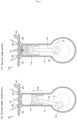
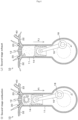
- Figs. 8 show an example of a valve opening/closing mechanism suitable for the six-cycle engine of Example 1 described above.
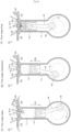
- Figs. 9 are essential portion sectional views of the camshaft, and Figs. 10 show a relationship between the camshaft and opening and closing of the valves 20 and 30.
- (A) of each of these drawings shows a state at the time of low-speed rotation, and (B) of each of these drawings shows a state at the time of high-speed rotation.
- the camshaft 300 is provided with a cam pulley 302, and a rotational drive force of a crankshaft timing gear 304 is transmitted through a timing belt 306.
- Reference sign 308 denotes a tension idler arranged to adjust a tension of the timing belt 306.
- the crankshaft timing gear 304 is provided on the above-described crankshaft 18.
- the camshaft 300 of the present example has a double structure consisting of a shaft outer 350 and a shaft inner 360 inserted in the shaft outer 350 as shown in Figs. 9 .
- the above-described cam pulley 302 is fixed to an outer circumference of the shaft outer 350.
- a helical screw 370 is provided, and at a bottom of the shaft outer 350 and the shaft inner 360, a pressing spring 372 is provided.
- a push rod 362 is provided, and on this push rod 362, and on this push rod 362, a governor 380 is provided.
- the governor 380 is a centrifugal type.
- various publicly known structures such as an electromagnetic type, a hydraulic type may be employed.
- the governor 380 closes and pushes the push rod 362 against a biasing force of the spring 372, and the shaft inner 360 is pushed into the shaft outer 350.
- the governor 380 is opened by a centrifugal force, and the push rod 362 and then the shaft inner 360 comes to be pushed against the spring 372. Therefore, the shaft inner 360 comes to slide in a direction toward the push rod 362 (refer to the arrow F9 in Fig. 9(B) ) while rotating due to the helical screw 370 (refer to the arrow F10 in Fig. 10(B) ).
- a required number of ball cams (rigid spheres) arranged to open the valves 20 and 30 are provided.
- the ball cam 400 is housed in a guide groove 402 provided in the shaft inner 360 so as not to escape but to protrude from the shaft outer 305.
- the guide groove 402 provided in the shaft inner 360 is formed along a helical direction of the above-described helical screw 370 so as to change in depth as shown Figs. 10 , and at the time of low-speed rotation, the ball cam 400 is at a deep position in the guide groove 402.
- the shaft inner 360 slides while rotating due to the helical screw 370, so that the ball cam 40 moves to a shallow position in the guide groove 402 and protrudes.
- the entirety of the camshaft 300 slides in the rotation direction, that is, an advance direction in which the angle is advanced in Fig. 5 .
- the camshaft 300 including such ball cams 400 is disposed as shown in Figs. 10 , the rocker arms 20A and 30A are biased by the ball cams 400 to push the valves 20 and 30, and accordingly, opening and closing operations shown in Figs. 1 to Figs. 4 are performed.
- Figs. 10 show one representative ball cam 400.
- the angles of opening of the valves 20 and 30 are approximately 60°, whereas in the two-cycle strokes, the angle is approximately 25° before the piston reaches the bottom dead center for first-stage exhaust, and is approximately 20° before the piston reaches the bottom dead center for scavenging and intake. Realization of this by using a general cam results in a protruding cam shape, and is not realistic. However, by applying the ball cam structure of the present example, the angle of opening of the valve 20, 30 can be adjusted by changing the protrusion amount by changing the diameter of the ball cam 400, and this is advantageous.
- Example 4 of the present invention is described.
- one kind of fuel such as only gasoline or only diesel fuel
- two kinds of fuel are used, and for example, in the four-cycle strokes of the first stage, diesel fuel is burned, and in the two-cycle strokes of the second stage, gasoline is burned.
- a fuel nozzle 514 is provided, and diesel fuel (light oil) is supplied from a diesel tank 510 through an injection pump 512.
- FIG. 5 and Fig. 6 Operations of an injection nozzle 232 at the gasoline fuel side and the injection pump 512 at the diesel fuel side are controlled by an ECU (Engine Control Unit) based on a crank angle detected by a crank angle sensor 520. That is, as shown in Fig. 5 and Fig. 6 , in the first stage, diesel fuel is supplied from the injection pump 512 and first-stage firing is performed, and in the second stage, in the same manner as in the examples described above, gasoline fuel is supplied from the injection nozzle 232 and second-stage ignition is performed.
- Figs. 12 show the first-stage strokes, and in the first-stage intake stroke shown in Fig. 12(A) , diesel fuel is supplied from the fuel nozzle 514 into the cylinder 11. Then, after first-stage compression in Fig. 12(B) , the first-stage firing stroke shown in Fig. 12(C) is entered. Other strokes are the same as in the examples described above.
- diesel fuel is used in the first stage and gasoline fuel is used in the second stage, and this brings about the following effects.
- Example 5 of the present invention discloses another combination of four-cycle strokes and two-cycle strokes.
- the timing of second-stage ignition is a timing retarded by 120 degrees. That is, next to a first-stage exhaust stroke of the four-cycle operation, second-stage intake ⁇ second-stage compression ⁇ second-stage ignition ⁇ second-stage combustion ⁇ scavenging and intake ⁇ first-stage intake are performed.
- the four-cycle and the two-cycle indicated in the drawings are indicated for convenience when focusing on the ignition timing at the top dead center.
- air can be supplied into the cylinder from an air nozzle 600 shown in Fig. 13(B) .
- the present invention is not limited to the examples described above, and can be variously modified without departing from the spirit of the present invention.
- the present invention includes the followings as well.
- an intake stroke ⁇ a compression stroke ⁇ a combustion stroke ⁇ an exhaust stroke in a four-cycle internal combustion engine are combined with an intake and compression stroke ⁇ a combustion and exhaust stroke in a two-cycle internal combustion engine, so that the pumping loss is reduced, the output is increased, and thermal efficiency is improved, and this is suitable for an internal combustion engine such as a gasoline engine of an automobile.
Landscapes
- Engineering & Computer Science (AREA)
- Mechanical Engineering (AREA)
- General Engineering & Computer Science (AREA)
- Chemical & Material Sciences (AREA)
- Combustion & Propulsion (AREA)
- Transportation (AREA)
- Oil, Petroleum & Natural Gas (AREA)
- Output Control And Ontrol Of Special Type Engine (AREA)
- Valve-Gear Or Valve Arrangements (AREA)
- Exhaust-Gas Circulating Devices (AREA)
- Hybrid Electric Vehicles (AREA)
- Valve Device For Special Equipments (AREA)
Applications Claiming Priority (3)
| Application Number | Priority Date | Filing Date | Title |
|---|---|---|---|
| JP2017090654A JP6359146B1 (ja) | 2017-04-28 | 2017-04-28 | 内燃機関及び駆動システム |
| PCT/JP2018/017279 WO2018199313A1 (ja) | 2017-04-28 | 2018-04-27 | 内燃機関及び駆動システム |
| EP18790609.4A EP3617477B1 (de) | 2017-04-28 | 2018-04-27 | Brennkraftmaschine und antriebssystem |
Related Parent Applications (1)
| Application Number | Title | Priority Date | Filing Date |
|---|---|---|---|
| EP18790609.4A Division EP3617477B1 (de) | 2017-04-28 | 2018-04-27 | Brennkraftmaschine und antriebssystem |
Publications (3)
| Publication Number | Publication Date |
|---|---|
| EP4442971A2 true EP4442971A2 (de) | 2024-10-09 |
| EP4442971A3 EP4442971A3 (de) | 2025-01-22 |
| EP4442971B1 EP4442971B1 (de) | 2026-01-14 |
Family
ID=62904863
Family Applications (2)
| Application Number | Title | Priority Date | Filing Date |
|---|---|---|---|
| EP18790609.4A Active EP3617477B1 (de) | 2017-04-28 | 2018-04-27 | Brennkraftmaschine und antriebssystem |
| EP24196068.1A Active EP4442971B1 (de) | 2017-04-28 | 2018-04-27 | Nockenwelle für verbrennungsmotor |
Family Applications Before (1)
| Application Number | Title | Priority Date | Filing Date |
|---|---|---|---|
| EP18790609.4A Active EP3617477B1 (de) | 2017-04-28 | 2018-04-27 | Brennkraftmaschine und antriebssystem |
Country Status (4)
| Country | Link |
|---|---|
| US (2) | US11225904B2 (de) |
| EP (2) | EP3617477B1 (de) |
| JP (1) | JP6359146B1 (de) |
| WO (1) | WO2018199313A1 (de) |
Families Citing this family (1)
| Publication number | Priority date | Publication date | Assignee | Title |
|---|---|---|---|---|
| JP6359146B1 (ja) | 2017-04-28 | 2018-07-18 | ▲福衛▼ 澤田 | 内燃機関及び駆動システム |
Citations (3)
| Publication number | Priority date | Publication date | Assignee | Title |
|---|---|---|---|---|
| JPH02119635A (ja) | 1988-10-28 | 1990-05-07 | Mazda Motor Corp | 6サイクルエンジン |
| JP2010031705A (ja) | 2008-07-26 | 2010-02-12 | Shigeru Sato | 内燃機関及び駆動システム |
| EP3617477A1 (de) | 2017-04-28 | 2020-03-04 | Fukuei Sawada | Brennkraftmaschine und antriebssystem |
Family Cites Families (25)
| Publication number | Priority date | Publication date | Assignee | Title |
|---|---|---|---|---|
| US1902996A (en) * | 1930-03-14 | 1933-03-28 | Gerard Paul | Valve actuating mechanism for internal combustion engines |
| US2249997A (en) * | 1938-11-12 | 1941-07-22 | Cities Service Oil Co | Internal combustion method |
| DE69421170T2 (de) | 1993-12-17 | 2000-07-06 | Christos Valasopoulos | Nockenspitze mit exzentrischer drehbewegung |
| US5402759A (en) * | 1994-07-08 | 1995-04-04 | Outboard Marine Corporation | Cylinder decompression arrangement in cam shaft |
| DE19914909A1 (de) * | 1999-04-01 | 2000-10-05 | Bayerische Motoren Werke Ag | Nockenwelle für eine Viertakt-Brennkraftmaschine |
| JP4244603B2 (ja) * | 2002-09-13 | 2009-03-25 | トヨタ自動車株式会社 | 可変サイクルエンジンにおける運転サイクルの切換制御 |
| JP2004108314A (ja) * | 2002-09-20 | 2004-04-08 | Toyota Motor Corp | 可変サイクルエンジンにおける運転サイクルの切換制御 |
| JP4165210B2 (ja) * | 2002-12-25 | 2008-10-15 | トヨタ自動車株式会社 | エンジン制御装置およびその方法 |
| AT501030B1 (de) * | 2004-06-03 | 2006-10-15 | Avl List Gmbh | Dekompressionseinrichtung für eine brennkraftmaschine |
| DE102006033024A1 (de) * | 2006-07-17 | 2008-01-24 | Robert Bosch Gmbh | Verfahren zum Betrieb einer Brennkraftmaschine |
| JP2008248756A (ja) * | 2007-03-29 | 2008-10-16 | Mitsubishi Motors Corp | 可変動弁装置 |
| US7481185B1 (en) * | 2007-08-14 | 2009-01-27 | Robert Bosch Gmbh | Multi-mode 2-stroke/4-stroke internal combustion engine |
| US8096050B2 (en) * | 2008-10-09 | 2012-01-17 | GM Global Technology Operations LLC | Double ballize camshaft assembly process |
| US7726268B2 (en) | 2008-10-20 | 2010-06-01 | Howard Kelem | Six stroke internal combustion engine and method of operation |
| DE102009005731B4 (de) * | 2009-01-22 | 2020-01-09 | Audi Ag | Ventiltrieb für Gaswechselventile mit geneigter Doppel-Kugelraste |
| JP5532953B2 (ja) * | 2010-01-21 | 2014-06-25 | トヨタ自動車株式会社 | 可変動弁システムの制御装置 |
| US9376941B2 (en) * | 2011-02-15 | 2016-06-28 | Shanghai Universoon Autoparts Co., Ltd. | Method and apparatus for resetting valve lift for use in engine brake |
| JP5826293B2 (ja) | 2012-01-27 | 2015-12-02 | ヤマハ発動機株式会社 | 掃気工程を有する燃料噴射式6サイクルエンジン |
| EP2653674A1 (de) * | 2012-04-19 | 2013-10-23 | Eaton S.r.l. | Hydraulisches Spielausgleichselement |
| JP6041753B2 (ja) * | 2012-11-21 | 2016-12-14 | 愛三工業株式会社 | エンジンの排気還流装置 |
| US8978603B2 (en) | 2012-12-12 | 2015-03-17 | Caterpillar Inc. | Six-stroke internal combustion engine valve activation system and method for operating such engine |
| JP6120143B2 (ja) | 2013-03-01 | 2017-04-26 | 三菱自動車工業株式会社 | 内燃機関のインタークーラ凝縮水排出装置 |
| DE112014006469B4 (de) | 2014-03-16 | 2020-11-26 | Shigeru Sato | Verbrennungsmotor und Antriebssystem |
| JP6098835B2 (ja) | 2014-09-25 | 2017-03-22 | マツダ株式会社 | エンジンの排気制御装置 |
| US20150122231A1 (en) * | 2015-01-12 | 2015-05-07 | Caterpillar Motoren Gmbh & Co. Kg | Method to disperse lubrication into a fuel supply for a fuel gas system |
-
2017
- 2017-04-28 JP JP2017090654A patent/JP6359146B1/ja active Active
-
2018
- 2018-04-27 WO PCT/JP2018/017279 patent/WO2018199313A1/ja not_active Ceased
- 2018-04-27 EP EP18790609.4A patent/EP3617477B1/de active Active
- 2018-04-27 EP EP24196068.1A patent/EP4442971B1/de active Active
- 2018-04-27 US US16/608,712 patent/US11225904B2/en active Active
-
2021
- 2021-11-30 US US17/538,630 patent/US11739685B2/en active Active
Patent Citations (3)
| Publication number | Priority date | Publication date | Assignee | Title |
|---|---|---|---|---|
| JPH02119635A (ja) | 1988-10-28 | 1990-05-07 | Mazda Motor Corp | 6サイクルエンジン |
| JP2010031705A (ja) | 2008-07-26 | 2010-02-12 | Shigeru Sato | 内燃機関及び駆動システム |
| EP3617477A1 (de) | 2017-04-28 | 2020-03-04 | Fukuei Sawada | Brennkraftmaschine und antriebssystem |
Also Published As
| Publication number | Publication date |
|---|---|
| EP3617477A4 (de) | 2021-01-27 |
| EP3617477B1 (de) | 2024-08-28 |
| US20220082048A1 (en) | 2022-03-17 |
| EP4442971A3 (de) | 2025-01-22 |
| US11739685B2 (en) | 2023-08-29 |
| JP2018189010A (ja) | 2018-11-29 |
| US11225904B2 (en) | 2022-01-18 |
| EP3617477A1 (de) | 2020-03-04 |
| EP4442971B1 (de) | 2026-01-14 |
| US20210054780A1 (en) | 2021-02-25 |
| JP6359146B1 (ja) | 2018-07-18 |
| WO2018199313A1 (ja) | 2018-11-01 |
Similar Documents
| Publication | Publication Date | Title |
|---|---|---|
| Wang | Introduction to engine valvetrains | |
| KR960007104B1 (ko) | 압축공기를 동력 매체로 하는 엔진 | |
| US20120227397A1 (en) | Gaseous fuel-powered engine system having turbo-compounding | |
| US9951679B2 (en) | Reciprocating internal combustion engine | |
| CN105683527B (zh) | 内燃机 | |
| US20070044778A1 (en) | Engine which operates repeatedly with a multi-stage combustion process | |
| US11739685B2 (en) | Camshaft for internal-combustion engine | |
| JP4980314B2 (ja) | 内燃機関及び駆動システム | |
| Turner et al. | 2-Stroke Engine Options for Automotive Use: A Fundamental Comparison of Different Potential Scavenging Arrangements for Medium-Duty Truck Applications | |
| JP6541825B2 (ja) | カムシャフト及び内燃機関 | |
| US8950368B2 (en) | Internal combustion engine and working cycle | |
| US20150285135A1 (en) | Combustion engine including an air injector, and power generating system including the combustion engine | |
| US8443773B2 (en) | Methods for controlling valves of an internal combustion engine, devices for controlling the valves, and engines employing the methods | |
| US7882631B2 (en) | Methods for controlling valves of an internal combustion engine, devices for controlling the valves, and engines employing the methods | |
| US9476349B1 (en) | Three and two half stroke freeboost internal combustion engine | |
| US11808231B2 (en) | Negative pressure operating method | |
| JP6177928B2 (ja) | 内燃機関及び駆動システム | |
| US7237537B2 (en) | Compression-ignition engine configuration for reducing pollutants and method and system thereof | |
| WO2014171017A1 (ja) | 内燃機関及び駆動システム |
Legal Events
| Date | Code | Title | Description |
|---|---|---|---|
| PUAI | Public reference made under article 153(3) epc to a published international application that has entered the european phase |
Free format text: ORIGINAL CODE: 0009012 |
|
| STAA | Information on the status of an ep patent application or granted ep patent |
Free format text: STATUS: THE APPLICATION HAS BEEN PUBLISHED |
|
| AC | Divisional application: reference to earlier application |
Ref document number: 3617477 Country of ref document: EP Kind code of ref document: P |
|
| AK | Designated contracting states |
Kind code of ref document: A2 Designated state(s): AL AT BE BG CH CY CZ DE DK EE ES FI FR GB GR HR HU IE IS IT LI LT LU LV MC MK MT NL NO PL PT RO RS SE SI SK SM TR |
|
| REG | Reference to a national code |
Ref country code: DE Ref legal event code: R079 Free format text: PREVIOUS MAIN CLASS: F01L0001047000 Ipc: F02B0075020000 Ref document number: 602018088672 Country of ref document: DE |
|
| PUAL | Search report despatched |
Free format text: ORIGINAL CODE: 0009013 |
|
| AK | Designated contracting states |
Kind code of ref document: A3 Designated state(s): AL AT BE BG CH CY CZ DE DK EE ES FI FR GB GR HR HU IE IS IT LI LT LU LV MC MK MT NL NO PL PT RO RS SE SI SK SM TR |
|
| RIC1 | Information provided on ipc code assigned before grant |
Ipc: F02D 23/00 20060101ALI20241217BHEP Ipc: F02D 39/04 20060101ALI20241217BHEP Ipc: F01L 1/344 20060101ALI20241217BHEP Ipc: F02B 25/14 20060101ALI20241217BHEP Ipc: F01L 1/047 20060101ALI20241217BHEP Ipc: F01L 1/18 20060101ALI20241217BHEP Ipc: F01L 1/08 20060101ALI20241217BHEP Ipc: F01L 1/053 20060101ALI20241217BHEP Ipc: F01L 1/02 20060101ALI20241217BHEP Ipc: F02M 26/22 20160101ALI20241217BHEP Ipc: F02M 26/07 20160101ALI20241217BHEP Ipc: F02M 26/06 20160101ALI20241217BHEP Ipc: F02M 26/05 20160101ALI20241217BHEP Ipc: F02D 19/06 20060101ALI20241217BHEP Ipc: F01L 13/00 20060101ALI20241217BHEP Ipc: F01L 1/356 20060101ALI20241217BHEP Ipc: F01L 1/04 20060101ALI20241217BHEP Ipc: B60W 20/15 20160101ALI20241217BHEP Ipc: B60K 6/24 20071001ALI20241217BHEP Ipc: F02B 75/02 20060101AFI20241217BHEP |
|
| STAA | Information on the status of an ep patent application or granted ep patent |
Free format text: STATUS: REQUEST FOR EXAMINATION WAS MADE |
|
| 17P | Request for examination filed |
Effective date: 20250515 |
|
| GRAP | Despatch of communication of intention to grant a patent |
Free format text: ORIGINAL CODE: EPIDOSNIGR1 |
|
| STAA | Information on the status of an ep patent application or granted ep patent |
Free format text: STATUS: GRANT OF PATENT IS INTENDED |
|
| INTG | Intention to grant announced |
Effective date: 20250801 |
|
| GRAS | Grant fee paid |
Free format text: ORIGINAL CODE: EPIDOSNIGR3 |
|
| GRAA | (expected) grant |
Free format text: ORIGINAL CODE: 0009210 |
|
| STAA | Information on the status of an ep patent application or granted ep patent |
Free format text: STATUS: THE PATENT HAS BEEN GRANTED |
|
| AC | Divisional application: reference to earlier application |
Ref document number: 3617477 Country of ref document: EP Kind code of ref document: P |
|
| AK | Designated contracting states |
Kind code of ref document: B1 Designated state(s): AL AT BE BG CH CY CZ DE DK EE ES FI FR GB GR HR HU IE IS IT LI LT LU LV MC MK MT NL NO PL PT RO RS SE SI SK SM TR |
|
| REG | Reference to a national code |
Ref country code: CH Ref legal event code: F10 Free format text: ST27 STATUS EVENT CODE: U-0-0-F10-F00 (AS PROVIDED BY THE NATIONAL OFFICE) Effective date: 20260114 Ref country code: GB Ref legal event code: FG4D |
|
| REG | Reference to a national code |
Ref country code: DE Ref legal event code: R096 Ref document number: 602018088672 Country of ref document: DE |
|
| REG | Reference to a national code |
Ref country code: IE Ref legal event code: FG4D |
|
| PGFP | Annual fee paid to national office [announced via postgrant information from national office to epo] |
Ref country code: GB Payment date: 20260324 Year of fee payment: 9 |