EP4439239A1 - Elektronische vorrichtung mit verbindungselement - Google Patents
Elektronische vorrichtung mit verbindungselement Download PDFInfo
- Publication number
- EP4439239A1 EP4439239A1 EP22916347.2A EP22916347A EP4439239A1 EP 4439239 A1 EP4439239 A1 EP 4439239A1 EP 22916347 A EP22916347 A EP 22916347A EP 4439239 A1 EP4439239 A1 EP 4439239A1
- Authority
- EP
- European Patent Office
- Prior art keywords
- electronic device
- circuit board
- battery
- conductive
- wire
- Prior art date
- Legal status (The legal status is an assumption and is not a legal conclusion. Google has not performed a legal analysis and makes no representation as to the accuracy of the status listed.)
- Pending
Links
Images


Classifications
-
- G—PHYSICS
- G06—COMPUTING OR CALCULATING; COUNTING
- G06F—ELECTRIC DIGITAL DATA PROCESSING
- G06F3/00—Input arrangements for transferring data to be processed into a form capable of being handled by the computer; Output arrangements for transferring data from processing unit to output unit, e.g. interface arrangements
- G06F3/01—Input arrangements or combined input and output arrangements for interaction between user and computer
- G06F3/011—Arrangements for interaction with the human body, e.g. for user immersion in virtual reality
-
- G—PHYSICS
- G06—COMPUTING OR CALCULATING; COUNTING
- G06F—ELECTRIC DIGITAL DATA PROCESSING
- G06F1/00—Details not covered by groups G06F3/00 - G06F13/00 and G06F21/00
- G06F1/16—Constructional details or arrangements
- G06F1/18—Packaging or power distribution
- G06F1/181—Enclosures
- G06F1/182—Enclosures with special features, e.g. for use in industrial environments; grounding or shielding against radio frequency interference [RFI] or electromagnetical interference [EMI]
-
- G—PHYSICS
- G02—OPTICS
- G02B—OPTICAL ELEMENTS, SYSTEMS OR APPARATUS
- G02B27/00—Optical systems or apparatus not provided for by any of the groups G02B1/00 - G02B26/00, G02B30/00
- G02B27/01—Head-up displays
-
- G—PHYSICS
- G02—OPTICS
- G02B—OPTICAL ELEMENTS, SYSTEMS OR APPARATUS
- G02B27/00—Optical systems or apparatus not provided for by any of the groups G02B1/00 - G02B26/00, G02B30/00
- G02B27/01—Head-up displays
- G02B27/017—Head mounted
-
- G—PHYSICS
- G02—OPTICS
- G02B—OPTICAL ELEMENTS, SYSTEMS OR APPARATUS
- G02B27/00—Optical systems or apparatus not provided for by any of the groups G02B1/00 - G02B26/00, G02B30/00
- G02B27/01—Head-up displays
- G02B27/017—Head mounted
- G02B27/0176—Head mounted characterised by mechanical features
-
- G—PHYSICS
- G02—OPTICS
- G02C—SPECTACLES; SUNGLASSES OR GOGGLES INSOFAR AS THEY HAVE THE SAME FEATURES AS SPECTACLES; CONTACT LENSES
- G02C11/00—Non-optical adjuncts; Attachment thereof
-
- G—PHYSICS
- G02—OPTICS
- G02C—SPECTACLES; SUNGLASSES OR GOGGLES INSOFAR AS THEY HAVE THE SAME FEATURES AS SPECTACLES; CONTACT LENSES
- G02C11/00—Non-optical adjuncts; Attachment thereof
- G02C11/10—Electronic devices other than hearing aids
-
- G—PHYSICS
- G06—COMPUTING OR CALCULATING; COUNTING
- G06F—ELECTRIC DIGITAL DATA PROCESSING
- G06F1/00—Details not covered by groups G06F3/00 - G06F13/00 and G06F21/00
- G06F1/16—Constructional details or arrangements
- G06F1/1613—Constructional details or arrangements for portable computers
- G06F1/163—Wearable computers, e.g. on a belt
-
- G—PHYSICS
- G06—COMPUTING OR CALCULATING; COUNTING
- G06F—ELECTRIC DIGITAL DATA PROCESSING
- G06F1/00—Details not covered by groups G06F3/00 - G06F13/00 and G06F21/00
- G06F1/16—Constructional details or arrangements
- G06F1/1613—Constructional details or arrangements for portable computers
- G06F1/1633—Constructional details or arrangements of portable computers not specific to the type of enclosures covered by groups G06F1/1615 - G06F1/1626
- G06F1/1635—Details related to the integration of battery packs and other power supplies such as fuel cells or integrated AC adapter
-
- G—PHYSICS
- G06—COMPUTING OR CALCULATING; COUNTING
- G06F—ELECTRIC DIGITAL DATA PROCESSING
- G06F1/00—Details not covered by groups G06F3/00 - G06F13/00 and G06F21/00
- G06F1/26—Power supply means, e.g. regulation thereof
-
- G—PHYSICS
- G06—COMPUTING OR CALCULATING; COUNTING
- G06F—ELECTRIC DIGITAL DATA PROCESSING
- G06F3/00—Input arrangements for transferring data to be processed into a form capable of being handled by the computer; Output arrangements for transferring data from processing unit to output unit, e.g. interface arrangements
- G06F3/01—Input arrangements or combined input and output arrangements for interaction between user and computer
-
- G—PHYSICS
- G02—OPTICS
- G02B—OPTICAL ELEMENTS, SYSTEMS OR APPARATUS
- G02B27/00—Optical systems or apparatus not provided for by any of the groups G02B1/00 - G02B26/00, G02B30/00
- G02B27/01—Head-up displays
- G02B27/017—Head mounted
- G02B2027/0178—Eyeglass type
Definitions
- the disclosure relates to an electronic device including a connection member.
- the disclosure relates to a wearable electronic device including a connection member.
- electronic devices may be reduced in size and weight to such an extent that the electronic devices may be used without great inconvenience even when the electronic devices are worn on a user's body.
- wearable electronic devices such as a head mounted device (HMD), a smartwatch (or band), a contact lens-type device, a ring-type device, a glove-type device, a shoe-type device, or a clothing-type device, are commercially available. Since the wearable electronic devices are directly worn on a user's body, portability and user accessibility may be improved.
- a head mounted device is a device used in the state of being worn on a user's head or face and may provide augmented reality (AR) to the user.
- AR augmented reality
- a head mounted device providing augmented reality may be implemented in the form of glasses, and may provide information about an object in the form of an image or text to the user in at least a partial space of the user's field of view.
- the head mounted device may provide virtual reality (VR) to the user. For example, by outputting independent images to the user's both eyes, respectively, and outputting a content provided from an external input to the user in the form of an image or sound, the head mounted device may provide an excellent sensation of immersion.
- VR virtual reality
- an electronic device may include a lens frame configured to accommodate a display member, a wearing member connected to the lens frame, a circuit board disposed inside the wearing member, a battery disposed inside the wearing member, and a connection member including a first end connected to the circuit board and a second end connected to the battery, wherein the connection member may include an elastic member formed of a conductive material and a wire at least partially surrounded by the elastic member, and the battery may be electrically connected to the circuit board via the elastic member and the wire.
- an electronic device may include a housing including a lens frame and a wearing member connected to the lens frame, a circuit board disposed inside the housing, a battery disposed inside the housing, and a connection member connected to the circuit board and the battery, wherein the connection member may include an elastic member including a coil spring and a wire at least partially surrounded by the coil spring and configured to electrically interconnect the battery and the circuit board, and a first ground area of the circuit board and a second ground area of the battery may electrically interconnected by the elastic member.
- FIG. 1 is a block diagram illustrating an electronic device in a network environment according to an embodiment of the disclosure.
- the electronic device 101 in the network environment 100 may communicate with an electronic device 102 via a first network 198 (e.g., a short-range wireless communication network), or an electronic device 104 or a server 108 via a second network 199 (e.g., a long-range wireless communication network).
- a first network 198 e.g., a short-range wireless communication network
- an electronic device 104 or a server 108 via a second network 199 (e.g., a long-range wireless communication network).
- the electronic device 101 may communicate with the electronic device 104 via the server 108.
- the electronic device 101 may include a processor 120, memory 130, an input module 150, a sound output module 155, a display module 160, an audio module 170, a sensor module 176, an interface 177, a connecting terminal 178, a haptic module 179, a camera module 180, a power management module 188, a battery 189, a communication module 190, a subscriber identification module (SIM) 196, or an antenna module 197.
- the components e.g., the connecting terminal 178) may be omitted from the electronic device 101, or one or more other components may be added in the electronic device 101.
- some of the components may be implemented as a single component (e.g., the display module 160).
- the processor 120 may execute, for example, software (e.g., a program 140) to control at least one other component (e.g., a hardware or software component) of the electronic device 101 coupled with the processor 120, and may perform various data processing or computation.
- the processor 120 may store a command or data received from another component (e.g., the sensor module 176 or the communication module 190) in volatile memory 132, process the command or the data stored in the volatile memory 132, and store resulting data in nonvolatile memory 134.
- another component e.g., the sensor module 176 or the communication module 190
- the processor 120 may include a main processor 121 (e.g., a central processing unit (CPU) or an application processor (AP)), or an auxiliary processor 123 (e.g., a graphics processing unit (GPU), a neural processing unit (NPU), an image signal processor (ISP), a sensor hub processor, or a communication processor (CP)) that is operable independently from, or in conjunction with, the main processor 121.
- a main processor 121 e.g., a central processing unit (CPU) or an application processor (AP)
- auxiliary processor 123 e.g., a graphics processing unit (GPU), a neural processing unit (NPU), an image signal processor (ISP), a sensor hub processor, or a communication processor (CP)
- the main processor 121 may be adapted to consume less power than the main processor 121, or to be specific to a specified function.
- the auxiliary processor 123 may be implemented as separate from, or as part of the main processor 121.
- the auxiliary processor 123 may control, for example, at least some of functions or states related to at least one component (e.g., the display module 160, the sensor module 176, or the communication module 190) among the components of the electronic device 101, instead of the main processor 121 while the main processor 121 is in an inactive (e.g., sleep) state, or together with the main processor 121 while the main processor 121 is in an active (e.g., executing an application) state.
- the auxiliary processor 123 e.g., an image signal processor or a communication processor
- the auxiliary processor 123 may include a hardware structure specified for artificial intelligence model processing.
- An artificial intelligence model may be generated by machine learning. Such learning may be performed, e.g., by the electronic device 101 where the artificial intelligence is performed or via a separate server (e.g., the server 108). Learning algorithms may include, but are not limited to, e.g., supervised learning, unsupervised learning, semi-supervised learning, or reinforcement learning.
- the artificial intelligence model may include a plurality of artificial neural network layers.
- the artificial neural network may be a deep neural network (DNN), a convolutional neural network (CNN), a recurrent neural network (RNN), a restricted Boltzmann machine (RBM), a deep belief network (DBN), a bidirectional recurrent deep neural network (BRDNN), deep Q-network or a combination of two or more thereof but is not limited thereto.
- the artificial intelligence model may, additionally or alternatively, include a software structure other than the hardware structure.
- the memory 130 may store various data used by at least one component (e.g., the processor 120 or the sensor module 176) of the electronic device 101.
- the various data may include, for example, software (e.g., the program 140) and input data or output data for a command related thereto.
- the memory 130 may include the volatile memory 132 or the nonvolatile memory 134.
- the program 140 may be stored in the memory 130 as software, and may include, for example, an operating system (OS) 142, middleware 144, or an application 146.
- OS operating system
- middleware middleware
- application application
- the input module 150 may receive a command or data to be used by another component (e.g., the processor 120) of the electronic device 101, from the outside (e.g., a user) of the electronic device 101.
- the input module 150 may include, for example, a microphone, a mouse, a keyboard, a key (e.g., a button), or a digital pen (e.g., a stylus pen).
- the sound output module 155 may output sound signals to the outside of the electronic device 101.
- the sound output module 155 may include, for example, a speaker or a receiver.
- the speaker may be used for general purposes, such as playing multimedia or playing record.
- the receiver may be used for receiving incoming calls. According to an embodiment, the receiver may be implemented as separate from, or as part of the speaker.
- the display module 160 may visually provide information to the outside (e.g., a user) of the electronic device 101.
- the display module 160 may include, for example, a display, a hologram device, or a projector and control circuitry to control a corresponding one of the display, hologram device, and projector.
- the display module 160 may include a touch sensor adapted to detect a touch, or a pressure sensor adapted to measure the intensity of force incurred by the touch.
- the audio module 170 may convert a sound into an electrical signal and vice versa. According to an embodiment, the audio module 170 may obtain the sound via the input module 150, or output the sound via the sound output module 155 or an external electronic device (e.g., an electronic device 102 (e.g., a speaker or a headphone)) directly or wirelessly coupled with the electronic device 101.
- an electronic device 102 e.g., a speaker or a headphone
- the sensor module 176 may detect an operational state (e.g., power or temperature) of the electronic device 101 or an environmental state (e.g., a state of a user) external to the electronic device 101, and then generate an electrical signal or data value corresponding to the detected state.
- the sensor module 176 may include, for example, a gesture sensor, a gyro sensor, an atmospheric pressure sensor, a magnetic sensor, an acceleration sensor, a grip sensor, a proximity sensor, a color sensor, an infrared (IR) sensor, a biometric sensor, a temperature sensor, a humidity sensor, or an illuminance sensor.
- the interface 177 may support one or more specified protocols to be used for the electronic device 101 to be coupled with the external electronic device (e.g., the electronic device 102) directly or wirelessly.
- the interface 177 may include, for example, a high definition multimedia interface (HDMI), a universal serial bus (USB) interface, a secure digital (SD) card interface, or an audio interface.
- HDMI high definition multimedia interface
- USB universal serial bus
- SD secure digital
- a connecting terminal 178 may include a connector via which the electronic device 101 may be physically connected with the external electronic device (e.g., the electronic device 102).
- the connecting terminal 178 may include, for example, an HDMI connector, a USB connector, an SD card connector, or an audio connector (e.g., a headphone connector).
- the haptic module 179 may convert an electrical signal into a mechanical stimulus (e.g., a vibration or a movement) or electrical stimulus which may be recognized by a user via his tactile sensation or kinesthetic sensation.
- the haptic module 179 may include, for example, a motor, a piezoelectric element, or an electric stimulator.
- the camera module 180 may capture a still image or moving images.
- the camera module 180 may include one or more lenses, image sensors, image signal processors, or flashes.
- the power management module 188 may manage power supplied to the electronic device 101.
- the power management module 188 may be implemented as at least part of, for example, a power management integrated circuit (PMIC).
- PMIC power management integrated circuit
- the battery 189 may supply power to at least one component of the electronic device 101.
- the battery 189 may include, for example, a primary cell which is not rechargeable, a secondary cell which is rechargeable, or a fuel cell.
- the communication module 190 may support establishing a direct (e.g., wired) communication channel or a wireless communication channel between the electronic device 101 and the external electronic device (e.g., the electronic device 102, the electronic device 104, or the server 108) and performing communication via the established communication channel.
- the communication module 190 may include one or more communication processors that are operable independently from the processor 120 (e.g., the AP) and supports a direct (e.g., wired) communication or a wireless communication.
- the communication module 190 may include a wireless communication module 192 (e.g., a cellular communication module, a short-range wireless communication module, or a global navigation satellite system (GNSS) communication module) or a wired communication module 194 (e.g., a local area network (LAN) communication module or a power line communication (PLC) module).
- a wireless communication module 192 e.g., a cellular communication module, a short-range wireless communication module, or a global navigation satellite system (GNSS) communication module
- GNSS global navigation satellite system
- wired communication module 194 e.g., a local area network (LAN) communication module or a power line communication (PLC) module.
- LAN local area network
- PLC power line communication
- a corresponding one of these communication modules may communicate with the external electronic device via the first network 198 (e.g., a short-range communication network, such as BluetoothTM, wireless-fidelity (Wi-Fi) direct, or infrared data association (IrDA)) or the second network 199 (e.g., a long-range communication network, such as a legacy cellular network, a 5G network, a next-generation communication network, the Internet, or a computer network (e.g., LAN or wide area network (WAN)).
- first network 198 e.g., a short-range communication network, such as BluetoothTM, wireless-fidelity (Wi-Fi) direct, or infrared data association (IrDA)
- the second network 199 e.g., a long-range communication network, such as a legacy cellular network, a 5G network, a next-generation communication network, the Internet, or a computer network (e.g., LAN or wide area network (WAN)).
- the wireless communication module 192 may identify or authenticate the electronic device 101 in a communication network, such as the first network 198 or the second network 199, using subscriber information (e.g., international mobile subscriber identity (IMSI)) stored in the subscriber identification module 196.
- subscriber information e.g., international mobile subscriber identity (IMSI)
- the wireless communication module 192 may support a 5G network, after a 4G network, and next-generation communication technology, e.g., new radio (NR) access technology.
- the NR access technology may support enhanced mobile broadband (eMBB), massive machine type communications (mMTC), or ultra-reliable and low-latency communications (URLLC).
- eMBB enhanced mobile broadband
- mMTC massive machine type communications
- URLLC ultra-reliable and low-latency communications
- the wireless communication module 192 may support a high-frequency band (e.g., the mmWave band) to achieve, e.g., a high data transmission rate.
- the wireless communication module 192 may support various technologies for securing performance on a high-frequency band, such as, e.g., beamforming, massive multiple-input and multiple-output (massive MIMO), full dimensional MIMO (FD-MIMO), array antenna, analog beam-forming, or large scale antenna.
- the wireless communication module 192 may support various requirements specified in the electronic device 101, an external electronic device (e.g., the electronic device 104), or a network system (e.g., the second network 199).
- the wireless communication module 192 may support a peak data rate (e.g., 20 Gbps or more) for implementing eMBB, loss coverage (e.g., 164 dB or less) for implementing mMTC, or U-plane latency (e.g., 0.5 ms or less for each of downlink (DL) and uplink (UL), or a round trip of 1 ms or less) for implementing URLLC.
- a peak data rate e.g., 20 Gbps or more
- loss coverage e.g., 164 dB or less
- U-plane latency e.g., 0.5 ms or less for each of downlink (DL) and uplink (UL), or a round trip of 1 ms or less
- the antenna module 197 may transmit or receive a signal or power to or from the outside (e.g., the external electronic device) of the electronic device 101.
- the antenna module may include an antenna including a radiating element composed of a conductive material or a conductive pattern formed in or on a substrate (e.g., a printed circuit board (PCB)).
- the antenna module 197 may include a plurality of antennas (e.g., array antennas). In such a case, at least one antenna appropriate for a communication scheme used in the communication network, such as the first network 198 or the second network 199, may be selected, for example, by the communication module 190 from the plurality of antennas.
- the signal or the power may then be transmitted or received between the communication module 190 and the external electronic device via the selected at least one antenna.
- another component e.g., a radio frequency integrated circuit (RFIC)
- RFIC radio frequency integrated circuit
- the antenna module 197 may form a mmWave antenna module.
- the mmWave antenna module may include a printed circuit board, an RFIC disposed on a first surface (e.g., the bottom surface) of the printed circuit board, or adjacent to the first surface and capable of supporting a designated high-frequency band (e.g., the mmWave band), and a plurality of antennas (e.g., array antennas) disposed on a second surface (e.g., the top or a side surface) of the printed circuit board, or adjacent to the second surface and capable of transmitting or receiving signals of the designated high-frequency band.
- a designated high-frequency band e.g., the mmWave band
- a plurality of antennas e.g., array antennas
- At least some of the above-described components may be coupled mutually and communicate signals (e.g., commands or data) therebetween via an inter-peripheral communication scheme (e.g., a bus, general purpose input and output (GPIO), serial peripheral interface (SPI), or mobile industry processor interface (MIPI)).
- an inter-peripheral communication scheme e.g., a bus, general purpose input and output (GPIO), serial peripheral interface (SPI), or mobile industry processor interface (MIPI)
- commands or data may be transmitted or received between the electronic device 101 and the external electronic device 104 via the server 108 coupled with the second network 199.
- Each of the external electronic devices 102 or 104 may be a device of a same type as, or a different type, from the electronic device 101.
- all or some of operations to be executed at the electronic device 101 may be executed at one or more external devices of the external electronic devices 102, 104, or 108. For example, if the electronic device 101 should perform a function or a service automatically, or in response to a request from a user or another device, the electronic device 101, instead of, or in addition to, executing the function or the service, may request the one or more external electronic devices to perform at least part of the function or the service.
- the one or more external electronic devices receiving the request may perform the at least part of the function or the service requested, or an additional function or an additional service related to the request, and transfer an outcome of the performing to the electronic device 101.
- the electronic device 101 may provide the outcome, with or without further processing of the outcome, as at least part of a reply to the request.
- a cloud computing, distributed computing, mobile edge computing (MEC), or client-server computing technology may be used, for example.
- the electronic device 101 may provide ultra low-latency services using, e.g., distributed computing or mobile edge computing.
- the external electronic device 104 may include an internet-of-things (IoT) device.
- the server 108 may be an intelligent server using machine learning and/or a neural network.
- the external electronic device 104 or the server 108 may be included in the second network 199.
- the electronic device 101 may be applied to intelligent services (e.g., smart home, smart city, smart car, or healthcare) based on 5G communication technology or IoT-related technology.
- the electronic device may be one of various types of electronic devices.
- the electronic devices may include, for example, a portable communication device (e.g., a smartphone), a computer device, a portable multimedia device, a portable medical device, a camera, a wearable device, or a home appliance.
- a portable communication device e.g., a smartphone
- a computer device e.g
- each of such phrases as “A or B”, “at least one of A and B”, “at least one of A or B”, “A, B, or C”, “at least one of A, B, and C”, and “at least one of A, B, or C”, may include any one of, or all possible combinations of the items enumerated together in a corresponding one of the phrases.
- such terms as “1st” and “2nd”, or “first” and “second” may be used to simply distinguish a corresponding component from another, and does not limit the components in other aspect (e.g., importance or order).
- an element e.g., a first element
- the element may be coupled with the other element directly (e.g., wiredly), wirelessly, or via a third element.
- module may include a unit implemented in hardware, software, or firmware, and may interchangeably be used with other terms, for example, “logic”, “logic block”, “part”, or “circuitry”.
- a module may be a single integral component, or a minimum unit or part thereof, adapted to perform one or more functions.
- the module may be implemented in a form of an application-specific integrated circuit (ASIC).
- ASIC application-specific integrated circuit
- each component e.g., a module or a program of the above-described components may include a single entity or multiple entities, and some of the multiple entities may be separately disposed in different components.
- one or more of the above-described components or operations may be omitted, or one or more other components or operations may be added.
- a plurality of components e.g., modules or programs
- the integrated component may still perform one or more functions of each of the plurality of components in the same or similar manner as they are performed by a corresponding one of the plurality of components before the integration.
- operations performed by the module, the program, or another component may be carried out sequentially, in parallel, repeatedly, or heuristically, or one or more of the operations may be executed in a different order or omitted, or one or more other operations may be added.
- FIG. 2 is a diagram of an electronic device according to an embodiment of the disclosure.
- the electronic device 200 is a glasses-type wearable electronic device, and a user may visually recognize a surrounding object or environment in the state of wearing the electronic device 200.
- the electronic device 200 may be a head mounted device (HMD) or smartglasses capable of providing an image directly in front of the user's eyes.
- the configuration of the electronic device 200 of FIG. 2 may be wholly or partly the same as that of the electronic device 101 of FIG. 1 .
- the electronic device 200 may include a housing 210 that defines the external appearance of the electronic device 200.
- the housing 210 may provide a space in which components of the electronic device 200 may be disposed.
- the housing 210 may include a lens frame 202 and one or more wearing members 203.
- the electronic device 200 may include one or more display members 201 capable of providing visual information to the user.
- the display members 201 may each include a lens, a display, a waveguide, and/or a module equipped with a touch circuit.
- the display members 201 may be transparent or translucent.
- the display members 201 may each include glass made of a translucent material or a window member the light transmittance of which is adjustable as the color concentration thereof is adjusted.
- a pair of display members 201 may be provided and disposed to correspond to the user's left and light eyes, respectively, in the state in which the electronic device 200 is worn on the user's body.
- the display members 201 may include a first display member 201a and a second display member 201b disposed to be spaced apart from the first display member 201a.
- the first display member 201a may be disposed to correspond to the user's right eye
- the second display member 201b may be disposed to correspond to the user's left eye.
- the lens frame 202 may at least partially accommodate the display members 201.
- the lens frame 202 may at least partially surround the edges of the display members 201.
- the lens frame 202 may position at least one of the display members 201 to correspond to the user's eyes.
- the lens frame 202 may be a rim of a general eyeglass structure.
- the lens frame 202 may include one or more closed curves surrounding the display members 201.
- the lens frame 202 may include a first lens frame end 202c and a second lens frame end 202d opposite the first lens frame end 202c.
- the first lens frame end 202c may be disposed adjacent to a first wearing member 203a
- the second lens frame end 202d may be disposed adjacent to a second wearing member 203b.
- the wearing members 203 may extend from the lens frame 202.
- the wearing members 203 may each extend from an end of the lens frame 202 and may be supported or positioned on the user's body (e.g., the ears), together with the lens frame 202.
- the wearing members 203 may each be rotatably coupled to the lens frame 202 via a hinge structure 229.
- the wearing members 203 may each include an inner side surface 231c configured to face the user's body and an outer side surface 231d opposite to the inner side surface.
- the wearing members 203 may be at least partially formed of a flexible material (e.g., rubber).
- at least a portion of each wearing member 203 may be formed in a band shape surrounding at least a portion of the user's body (e.g., an ear).
- the wearing members 203 may include a first wearing member 203a and a second wearing member 203b.
- the first wearing member 203a may be connected to the first lens frame end 202c of the lens frame 202
- the second wearing member 203b may be connected to the second lens frame end 202d of the lens frame 202.
- the electronic device 200 may include hinge structures 229 connected to the wearing members 203 and the lens frame 202.
- the user may carry or store the electronic device 200 in the state in which the wearing members 203 are folded to partially overlap the lens frame 202 by using the hinge structures 229.
- the hinge structures 229 may include a first hinge structure 229a connected to a portion (e.g., the first lens frame end 202c) of the lens frame 202 and the first wearing member 203a and a second hinge structure 229b connected to a portion (e.g., the second lens frame end 202d) of the lens frame 202 and the second wearing member 203b.
- FIG. 3 is a diagram of an internal configuration of an electronic device according to an embodiment of the disclosure.
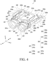
- FIG. 4 is a diagram of the electronic device according to an embodiment of the disclosure.
- the electronic device 200 may include display members 201, a lens frame 202, wearing members 203, hinge structures 229, one or more circuit boards 241, one or more batteries 243, one or more power transmission structures 246, a camera modules 250, and sensor modules 280.
- the configurations of the display members 201, the lens frame 202, the wearing members 203, and the hinge structures 229 of FIG. 3 and/or FIG. 4 may wholly or partly the same as those of the display members 201, the lens frame 202, the wearing members 203, and the hinge structures 229 of FIG. 2 .
- the electronic device 200 may acquire and/or recognize visual images regarding an object or environment in a direction, in which the user gazes or the electronic device 200 is oriented (e.g., the -Y direction) by using the camera modules 250 (e.g., the camera module 180 of FIG. 1 ) and may receive information about the object or environment from an external electronic device (e.g., the electronic devices 102 and 104 or the server 108 of FIG. 1 ) via a network (e.g., the first network 198 or the second network 199 of FIG. 1 ).
- the electronic device 200 may provide, to the user, the received information about the object or environment in an acoustic or visual form.
- the electronic device 200 may provide, to the user, the received information about the object or environment via the display members 201 in a visual form by using a display module (e.g., the display module 160 in FIG. 1 ).
- a display module e.g., the display module 160 in FIG. 1
- the electronic device 200 may implement augmented reality by implementing the information about the object or environment in a visual form and combining the information with an actual image of the environment around the user.
- the display member 201 may include a first surface F1 oriented in a direction (e.g., in the -Y direction) in which external light is incident and a second surface F2 facing away from the first surface F1 (e.g., in the +Y direction).
- a first surface F1 oriented in a direction (e.g., in the -Y direction) in which external light is incident
- a second surface F2 facing away from the first surface F1 (e.g., in the +Y direction).
- the first surface F1 oriented in a direction (e.g., in the -Y direction) in which external light is incident
- a second surface F2 facing away from the first surface F1 (e.g., in the +Y direction).
- the lens frame 202 may include at least two frames.
- the lens frame 202 may include a first frame 202a and a second frame 202b.
- the first frame 202a may be a frame of a portion facing the user's face
- the second frame 202b may be a portion of the lens frame 202 spaced apart from the first frame 202a in the user's gazing direction (e.g., the -Y direction).
- the electronic device 200 may include light output modules 211 configured to provide an image and/or a video to the user.
- the light output modules 211 may include display panels capable of outputting an image, and lenses corresponding to the user's eyes and configured to guide the image to the display members 201.
- the user may acquire an image output from the display panels of the light output modules 211 through the lenses of the light output modules 211.
- the light output modules 211 may each include a device configured to display various pieces of information.
- the light output modules 211 may each include at least one of a liquid crystal display (LCD), a digital mirror device (DMD), a liquid crystal-on-silicon (LCoS) display device, an organic light-emitting diode (OLED), or a micro light-emitting diode (a micro-LED).
- the electronic device 200 may include light sources configured to emit light to the display areas of the light output modules 211 and/or the display members 201.
- the light output modules 211 and/or the display members 201 each include one of an organic light emitting diode or a micro-LED
- the electronic device 200 may provide a virtual image to the user without including a separate light source.
- each of the light output modules 211 may be at least partially disposed inside the housing 210.
- the light output modules 211 may be disposed on the wearing members 203 or the lens frame 202 to correspond to the user's right eye and left eye, respectively.
- the light output modules 211 may be connected to the display members 201, respectively, and may provide an image to the user via the display members 201.
- an image output from the light output modules 211 is incident on the display members 201 via input optical members located at one ends of the display members 201, and may be emitted to the user's eyes through waveguides and output optical members each of which is located in at least a portion of corresponding one of the display members 201.
- the electronic device 200 may include circuit boards 241 each of which accommodates components for driving the electronic device 200 (e.g., a printed circuit board (PCB), a printed board assembly (PBA), an FPCB (flexible PCB), or a rigid-flexible PCB (RFPCB).
- the circuit boards 241 may each include at least one integrated circuit chip, and at least one of the processor 120, the memory 130, the power management module 188, or the communication module 190 of FIG. 1 may be provided in the integrated circuit chip.
- the circuit boards 241 may be disposed in the wearing members 203 of the housing 210, respectively.
- the circuit boards 241 may include a first circuit board 241a disposed in the first wearing member 203a and a second circuit board 241b disposed in the second wearing member 203b.
- the circuit boards 241 may be electrically connected to the batteries 243 via power transmission structures 246, respectively.
- the circuit boards 241 may be interposer boards.
- the batteries 243 may be electrically connected to the components (e.g., the light output modules 211, the circuit boards 241, the speaker modules 245, the microphone modules 247, and/or the camera modules 250) of the electronic device 200, and may supply power to the components of the electronic device 200.
- the components e.g., the light output modules 211, the circuit boards 241, the speaker modules 245, the microphone modules 247, and/or the camera modules 250
- the batteries 243 may be at least partially disposed within the wearing members 203, respectively.
- the batteries 243 may include a first battery 243a disposed in the first wearing member 203a and a second battery 243b disposed in the second wearing member 203b.
- the batteries 243 may be disposed adjacent to the ends 203a and 203d of the wearing members 203, respectively.
- the speaker modules 245 may convert an electrical signal into sound.
- the speaker modules 245 may be at least partially disposed inside the wearing members 203 of the housing 210, respectively.
- the speaker modules 245 may be located in the wearing members 203 to correspond to the user's ears, respectively.
- the speaker modules 245 may be disposed next to the circuit boards 241, respectively.
- the speaker modules 245 may be disposed between the circuit boards 241 and the batteries 243, respectively.
- the speaker modules 245 may be disposed on the circuit boards 241, respectively.
- the speaker modules 245 may be disposed between the circuit boards 241 and the inner cases (e.g., the inner cases 231 in FIG. 4 ), respectively.
- the electronic device 200 may include power transmission structures 246 configured to transmit power of the batteries 243 to electronic components (e.g., the light output modules 211) of the electronic device 200.
- the power transmission structures 246 may be electrically connected to the batteries 243 and/or the circuit boards 241, and the circuit boards 241 may transmit, to the light output modules 211, respectively, power received via the power transmission structures 246.
- the power transmission structures 246 may have a configuration capable of transmitting power.
- the power transmission structures 246 may each include a flexible printed circuit board or wire.
- the wire may include a plurality of cables.
- the shape of the power transmission structures 246 may be variously modified in consideration of the number and/or type of cables, or the like.
- microphone modules 247 may convert sound into an electrical signal.
- the microphone modules 247 may be disposed within the lens frame 202.
- one or more microphone modules 247 may be disposed at the lower end (e.g., in the -X-axis direction) and/or the upper end (e.g., the X-axis direction) of the electronic device 200.
- the electronic device 200 may more clearly recognize the user's voice by using voice information (e.g., sound) acquired from the one or more microphone modules 247.
- the electronic device 200 may distinguish voice information and ambient noise from each other. For example, the electronic device 200 may clearly recognize the user's voice and may perform a function of reducing ambient noise (e.g., noise canceling).
- additional information e.g., low-frequency vibration of the user's skin and bone
- the camera modules 250 may capture a still image and/or a video image.
- the camera modules 250 may each include at least one of a lens, at least one image sensor, an image signal processor, or a flash.
- the camera modules 250 may be disposed in the lens frame 202 and disposed around the display members 201, respectively.
- the camera modules 250 may include one or more first camera modules 251.
- the first camera modules 251 may image the trajectory of the user's eyes (e.g., pupils) or gaze.
- the first camera modules 251 may each include a light-emitting unit (e.g., an IR LED) configured to emit light in an infrared band, and a camera structure configured to image a reflection pattern of the light emitted by the light emitting unit to the user's eyes.
- the processor e.g., the processor 120 in FIG. 1
- the trajectory of the user's eyes or gaze may be tracked by using the plurality of first camera modules 251 having the same standard and performance.
- the first camera modules 251 may periodically or aperiodically transmit information related to the trajectory of the user's eyes or gaze (e.g., trajectory information) to the processor (e.g., the processor 120 in FIG. 1 ). According to another embodiment, the first camera modules 251 may transmit the trajectory information to the processor when detecting that the user's gaze has changed based on the trajectory information (e.g., when the eyes have moved more than a reference value in the state in which the head does not move).
- trajectory information e.g., trajectory information
- the processor e.g., the processor 120 in FIG. 1
- the first camera modules 251 may transmit the trajectory information to the processor when detecting that the user's gaze has changed based on the trajectory information (e.g., when the eyes have moved more than a reference value in the state in which the head does not move).
- the camera modules 250 may include a second camera module 253.
- the second camera module 253 may capture an external image.
- the second camera module 253 may capture an external image through a second optical hole 223 provided in the second frame 202b.
- the second camera module 253 may include a high-resolution color camera and may be a high-resolution (HR) or photo-video (PV) camera.
- the second camera module 253 may provide an auto focus (AF) function and an optical image stabilizer (OIS) function.
- AF auto focus
- OIS optical image stabilizer
- the electronic device 200 may include a flash located adjacent to the second camera module 253.
- the flash may provide light for increasing the brightness (e.g., illuminance) around the electronic device 200 when acquiring an external image of the second camera module 253, and may reduce difficulty of acquiring an image due to a dark environment, mixing of various light sources, and/or reflection of light.
- the camera modules 250 may include one or more third camera modules 255.
- the third camera modules 255 may image a user's motion through the first optical holes 221 provided in the lens frame 202.
- the third camera modules 255 may image the user's gesture (e.g., a hand gesture).
- the third camera modules 255 and/or first optical holes 221 may be disposed respective at the opposite ends of the lens frame 202 (e.g., the second frame 202b) (e.g., the opposite ends of the lens frame 202 (e.g., the second frame 202b) in the X direction).
- the third camera modules 255 may be global shutter (GS) type cameras.
- GS global shutter
- the third camera modules 255 may provide 360-degree spatial (e.g., omnidirectional) or positional recognition and/or movement recognition using cameras that support 3 degrees of freedom (DoF) or 6 DoF.
- the third camera modules 255 may perform a movement path tracking function (simultaneous localization and mapping (SLAM)) and a user movement recognition function using a plurality of global shutter type cameras of the same standard and performance as stereo cameras.
- the third camera modules 255 may each include an infrared (IR) camera (e.g., a time of flight (ToF) camera or a structured light camera).
- the IR camera may be operated as at least a portion of a sensor module (e.g., the sensor module 176 in FIG. 1 ) for detecting a distance to a subject.
- the first camera modules 251 and the third camera modules 255 may be replaced with a sensor module (e.g., the sensor module 176 in FIG. 1 ).
- the sensor module may include at least one of a vertical cavity surface emitting laser (VCSEL), an infrared sensor, and/or a photodiode.
- the photodiode may include a positive intrinsic negative (PIN) photodiode or an avalanche photodiode (APD). The photodiode may be interpreted as a photo detector or a photo sensor.
- At least one of the first camera modules 251, the second camera module 253, or the third camera modules 255 may include a plurality of camera modules.
- the second camera module 253 may include a plurality of lenses (e.g., wide-angle and telephoto lenses) and image sensors, and may be disposed on one surface (e.g., the surface oriented in the -Y-axis direction) of the electronic device 200.
- the electronic device 200 may include a plurality of camera modules having different attributes (e.g., angles of view) or functions, respectively, and may control the camera modules to change the angles of view thereof based on the user's selection and/or trajectory information.
- at least one of the plurality of camera modules may be a wide-angle camera, and at least another one of the camera modules may be a telephoto camera.
- the processor may determine the movement of the electronic device 200 and/or the user's movement using the information of the electronic device 200 acquired by using at least one of the gesture sensor, the gyro sensor, or the acceleration sensor of the sensor module (e.g., the sensor module 176 in FIG. 1 ) and the user's movement (e.g., the approach of the user's body to the electronic device 200) acquired by using the third camera modules 255.
- the processor e.g., the processor 120 in FIG. 1
- the processor may determine the movement of the electronic device 200 and/or the user's movement using the information of the electronic device 200 acquired by using at least one of the gesture sensor, the gyro sensor, or the acceleration sensor of the sensor module (e.g., the sensor module 176 in FIG. 1 ) and the user's movement (e.g., the approach of the user's body to the electronic device 200) acquired by using the third camera modules 255.
- the electronic device 200 may include a magnetic (geomagnetic) sensor capable of measuring an azimuth using a magnetic field and a line of magnetic force and/or a Hall sensor capable of acquiring movement information (e.g., a movement direction or a movement distance) using the intensity of the magnetic field.
- the processor may determine the movement of the electronic device 200 and/or the movement of the user based on information acquired from a magnetic (geomagnetic) sensor and/or a Hall sensor.
- the electronic device 200 may perform an input function (e.g., a touch and/or a pressure detection function) capable of interacting with the user.
- an input function e.g., a touch and/or a pressure detection function
- components configured to perform a touch and/or a pressure detection function e.g., a touch sensor and/or a pressure sensor
- the electronic device 200 may control a virtual image output through the display members 201 based on the information acquired via the components.
- the sensors related to a touch detection function and/or a pressure detection function may be configured in various types, such as a resistive type, a capacitive type, an electromagnetic (EM) type, or an optical type.
- all or some of the components configured to perform a touch detection function and/or a pressure detection function may be the same as those of the input module 150 of FIG. 1 .
- the electronic device 200 may include lens structures 270.
- the lens structures 270 may refract at least a part of light.
- the lens structures 270 may be prescription lenses having a specified refractive power.
- the lens structures 270 may be at least partially disposed behind the window member of the display members 201 (e.g., in the +Y direction).
- the lens structures 270 may be located between the display members 201 and the user's eyes.
- the housing 210 may include hinge covers 227 capable of partially concealing the hinge structures 229, respectively.
- the other portions of the hinge structures 229 may be accommodated or concealed between inner cases 231 and outer cases 233, which will be described later.
- the wearing members 203 may each include an inner case 231 and an outer case 233.
- the inner case 231 is, for example, a case configured to face the user's body or to come into direct contact with the user's body, and may be made of a material having a low thermal conductivity (e.g., a synthetic resin).
- the inner case 231 may include an inner side surface (e.g., the inner side surface 231c in FIG. 2 ) facing the user's body.
- the outer cases 233 may include, for example, a material (e.g., a metal material) capable of at least partially transferring heat, and may be coupled to face the inner cases 231, respectively.
- the outer cases 233 may each include an outer side surface (e.g., the outer side surface 231d in FIG. 2 ) opposite to the inner side surface 231c.
- at least one of the circuit boards 241 or the speaker modules 245 may be accommodated in a space separated from the battery 243 within the wearing member 203.
- the inner cases 231 may include a first case 231a including a circuit board 241 and/or a speaker module 245 and a second case 231b configured to accommodate a battery 243
- the outer cases 233 may include a third case 233a coupled to face the first case 231a and a fourth case 233b coupled to face the second case 231b.
- first case parts 231a and 233a may be coupled to accommodate the circuit board 241 and/or the speaker module 245, and the second case 231b and the fourth case 233b (hereinafter, “second case parts 231b and 233b”) may be coupled to accommodate the battery 243.
- the first case parts 231a and 233a may be rotatably coupled to the lens frame 202 via the hinge structures 229, and the second case parts 231b and 233b may be connected to or mounted on the ends of the first case parts 231a and 233a via the connection structures 235.
- the portions of the connection structures 235 that come into contact with the user's body may be made of a material having low thermal conductivity (e.g., an elastic material such as silicone, polyurethane, or rubber), and the portions that do not come into contact with the user's body may be made of a material having a high thermal conductivity (e.g., a metal material).
- connection structures 235 block heat from being transferred to portions that come into contact with the user's body, and may distribute or release heat through the portions that do not come into contact with the user's body.
- the portions of the connection structures 235 that are configured to come into contact with the user's body may be interpreted as portions of the inner cases 231, and the portions of the connection structures 235 that do not come into contact with the user's body may be interpreted as portions of the outer cases 233.
- the first case 231a and the second case 231b may be integrally configured without a connection structure 235
- the third case 233a and the fourth case 233b may be integrally configured without a connection structure 235
- other components e.g., the antenna module 197 of FIG. 1
- information about an object or environment may be provided from an external electronic device (e.g., the electronic device 102 or 104 or the server 108 in FIG. 1 ) by using a communication module 190 via a network (e.g., the first network 198 or the second network 199 in FIG. 1 ).
- connection structures 235 may be formed of a flexible material (e.g., rubber and/or silicone).
- a flexible material e.g., rubber and/or silicone
- the shape of the connection structures 235 may be deformed to correspond to the user's body.
- each connection structure 235 may accommodate at least a portion of a connection member (e.g., the connection member 300 in FIG. 5 ).
- the sensor module 280 may detect light passing through the display members 201.
- the sensor module 280 may include a first sensor module 281 capable of detecting light passing through the first display member 201a, and a second sensor module 282 capable of detecting light passing through the second display member 201b.
- the first sensor module 281 may detect light at the rear side (e.g., +Y direction) of the first display member 201a
- the second sensor module 282 may detect light at the rear side of the second display member 201b.
- the sensor modules 280 may include a third sensor module 283 capable of detecting light at the front side (e.g., - Y direction) of the display members 201.
- the third sensor module 283 may detect light at the front side (e.g., -Y direction) of the display members 201.
- the sensor modules 280 may be illuminance sensors.
- the configuration of the third sensor module 283 be wholly or partly the same as that of the second camera module 253.
- FIG. 5 is a diagram of the internal structure of the electronic device according to an embodiment of the disclosure.
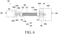
- FIG. 6 is a diagram of the electronic device including a connection member according to an embodiment of the disclosure.
- FIG. 7 is a diagram of an electrical connection structure between the connection member and a circuit board according to an embodiment of the disclosure.
- the electronic device 200 may include a housing 210, a connection member 300, a circuit board 400, and a battery 500.
- the configurations of the housing 210, the circuit board 400, and the battery 500 of FIG. 5 may be wholly or partly the same as those of the housing 210, the circuit board 241, and the battery 243 of FIGS. 3 and 4 .
- connection member 300 may interconnect the circuit board 400 and the battery 500.
- connection member 300 may electrically interconnect the circuit board 400 and the battery 500.
- the battery 500 may be electrically connected to a processor (e.g., the processor 120 in FIG. 1 ) and/or a power management module (e.g., the power management module 186 in FIG. 1 ) located on the circuit board 400 via the connection member 300.
- the circuit board 400 and/or the battery 500 may each operate as a ground that provides a reference potential. The current of the circuit board 400 may flow to the battery 500 via the connection member 300.
- the shape of at least a portion of the housing 210 of the electronic device 200 may be changed.
- at least a portion of the connection structure e.g., the connection structure 235 in FIG. 4
- the connection structure 235 in FIG. 4 may be bent to increase user convenience.
- connection member 300 may be disposed in the connection structure 235. At least a portion of the connection member 300 may be deformed or bent together with the connection structure 235. According to an embodiment, the connection member 300 may be referred to as a goose neck hinge and/or a bellows structure.
- connection member 300 may mechanically interconnect the circuit board 400 and the battery 500.
- the connection member 300 may include a first end 300a connected to the circuit board 400 and a second end 300b located opposite to the first end 300a and connected to the battery 500.
- the connection member 300 may be disposed in the housing 210.
- at least a portion of the connection member 300 may be accommodated in the connection structure (e.g., the connection structure 235 in FIG. 4 ) of the housing 210.
- connection member 300 may include an elastic member 310 and a wire 320.
- the configuration of the wire 320 may be wholly or partly the same as the configuration of the power transmission structure 246 of FIG. 3 and/or FIG. 4 .
- the wire 320 may have various shapes according to the design of the electronic device 200.
- the elastic member 310 may electrically interconnect the circuit board 400 and the battery 500.
- at least a portion of the elastic member 310 may be formed of a conductive material.
- at least some of the current of the circuit board 400 may flow to the battery 500 via the elastic member 310, or at least some of the current of the battery 500 may flow to the circuit board 400 via the elastic member 310.
- the elastic member 310 may protect the wire 320 from an external impact.
- the elastic member 310 may surround at least a portion of the wire 320.
- the elastic member 310 may be a coil spring.
- the elastic member 310 may include a third end 310a facing the circuit board 400 and a fourth end 310b located opposite to the third end 310a and facing the battery 500.
- the wire 320 may electrically interconnect the circuit board 400 and the battery 500.
- the current output from the battery 500 may be transmitted to the circuit board 400 via the wire 320.
- the wire 320 may include a fifth end 320a connected to a first power terminal 400a of the circuit board 400 and a sixth end 320b located opposite to the fifth end 320a and connected to a second power terminal 500a of the battery 500.
- a power management module e.g., the power management module 188 in FIG. 1
- the power management module 188 may be electrically connected to the battery 500 via the first power terminal 400a, the wire 320, and the second power terminal 500a.
- the wire 320 may mechanically interconnect the circuit board 400 and the battery 500.
- the wire 320 may include a flexible conductive material (e.g., metal).
- At least a portion of the wire 320 may be located inside the elastic member 310.
- at least a portion of the wire 320 may be surrounded by the elastic member 310.
- the elastic member 310 and the wire 320 may be electrically separated from each other.
- the wire 320 may include an insulating coating forming at least a portion of an outer circumferential surface of the wire 320.
- the insulating coating may be referred to as a sheath surrounding an internal wire that provides a path for current to flow.
- the wire 320 may include at least one conductive line.
- the wire 320 may include at least one conductive line and an insulating coating surrounding the at least one conductive line.
- the connection member 300 may include a conductive member 330 connected to the elastic member 310.
- the conductive member 330 may include a first conductive member 331 electrically connected to the third end 310a of the elastic member 310 and a second conductive member 332 electrically connected to the fourth end 310b of the elastic member 310.
- the first conductive member 331 may be disposed between the elastic member 310 and the circuit board 400.
- the second conductive member 332 may be disposed between the elastic member 310 and the battery 500.
- the conductive member 330 may surround at least a portion of the wire 320.
- the connection member 300 may include first conductive plates 341 and 342 extending from the first conductive member 331.
- the first conductive plates 341 and 342 may be connected to a first ground area 400b, 400c of the circuit board 400.
- the first conductive plates 341 and 342 may include a first plate 341 and a second plate 342 spaced apart from the first plate 341.
- the wire 320 may be located between the first plate 341 and the second plate 342.
- the first ground area 400b, 400c may be interpreted as a metal and/or conductive portion of the circuit board 400 for providing a reference potential.
- the conductive member 300 may include a second conductive plate 343 extending from the second conductive member 332.
- the second conductive plate 343 may be connected to a second ground area 500b of the battery 500.
- the second ground area 500b may be interpreted as a metal and/or conductive portion of the battery 500 for providing a reference potential.
- the first ground area 400b and the second ground area 500b may function as a single ground due to the connection member 300.
- the conductive member 330 may provide a path through which current flows, together with the elastic member 310.
- the circuit board 400 may be electrically connected to the battery 500 via the first conductive member 331, the elastic member 310, and the second conductive member 332.
- the current of the circuit board 400 may flow to the battery 500 via the first conductive plate 341, the first conductive member 331, the elastic member 310, the second conductive member 332, and the second conductive plate 343.
- the electronic device 200 may use, as a ground structure, the second ground area 500b of the battery 500 together with the first ground area 400b of the printed circuit board 400.
- the ground structure may be referred to as a ground or an earth.
- the first end 300a of the connection member 300 may include the first conductive plate 341, the second conductive plate 342, and/or a third end 320a of the wire 320.
- the second end 300b of the connection member 300 may include a fourth end 320b of the wire 320 and/or the second conductive plate 343.
- the electronic device 200 may include a cable structure 305 spaced apart from the connection member 300.
- the cable structure 305 may be electrically connected to a connection terminal for charging the electronic device 200 (e.g., the connection terminal 307 in FIG. 10 ) and the circuit board 400.
- a connection terminal for charging the electronic device 200 e.g., the connection terminal 307 in FIG. 10
- an electrical signal and/or current acquired from an external electronic device by using the connection terminal 307 may be transmitted to the circuit board 400 and/or the battery 500.
- at least a portion of the cable structure 305 may be arranged in substantially parallel to at least a portion of the wire 320.
- connection member 300 may include at least one fastening member 303 for connecting or fixing a plate (e.g., the first conductive plate 341 and/or the second conductive plate 343) to the circuit board 400.
- the fastening member 303 may have a screw or boss structure.
- connection member 300 is illustrated as being located in the housing 210 between the circuit board 400 and the battery 500, but the position of the connection member 300 is not limited thereto.
- the connection member 300 may be located inside the housing 210 and may mechanically and/or electrically connect the components of the electronic device 200.
- the connection member 300 may be located inside the housing 210 corresponding to the hinge structure (e.g., the hinge structure 229 in FIG. 2 ).
- the connection member 300 may be electrically connected the battery 500 via to a circuit board (e.g., the first circuit board 241a and/or the second circuit board 241b of FIG. 4 ) without being directly connected to the battery 500.
- the shape and/or structure of the second end 300b may correspond to the shape and/or structure of the first end 300a.
- the structure of the second conductive plate 343 of the second end 300b may be substantially the same as that of the first conductive plates 341 and 342 of the first end 300a.
- FIG. 8 is a diagram of an electronic device including a connection member according to an embodiment of the disclosure.
- FIG. 9 is a diagram of an electrical connection structure between the connection member and the circuit board of FIG. 8 according to an embodiment of the disclosure.
- the electronic device 200 may include a connection member 300, a fastening member 303, a cable structure 305, a circuit board 400, and a battery 500.
- the configurations of the connection structure 300, the fastening member 303, the cable structure 305, the circuit board 400, and the battery 500 of FIG. 8 and/or FIG. 9 are wholly or partly the same as those of the connection member 300, the fastening member 303, the cable structure 305, the circuit board 400, and the battery 500 of FIG. 7 and/or FIG. 8 .
- the connection member 300 may include a third plate 344.
- the third plate 344 may be electrically connected to the wire 320.
- the third plate 344 may be interpreted as a conductive metal extending from the wire 320.
- the current output from the battery 500 may be transmitted to the first power terminal 400a of the circuit board 400 via the wire 320 and the third plate 344.
- the third plate 344 may not be electrically connected to the elastic member 310, the first conductive member 331, and the first conductive plate 341.
- FIG. 10 is a diagram of an electronic device including a connection member and a connection terminal according to an embodiment of the disclosure.
- the electronic device 200 may include a connection member 300, a cable structure 305, a circuit board 400, and a battery 500.
- the configurations of the connection structure 300, the cable structure 305, the circuit board 400, and the battery 500 of FIG. 10 are wholly or partly the same as those of the connection member 300, the fastening member 303, the cable structure 305, the circuit board 400, and the battery 500 of FIG. 6 and/or FIG. 7 .
- the electronic device 200 may include a connection terminal 307.
- the connection terminal 307 may include a pin structure 307a to be connected to an external electronic device (e.g., a charging cable or a charging case) and a transmission member 307b electrically connected to the pin structure 307a.
- the pin structure 307a may include an elastic body (e.g., a spring) and a barrel structure that is at least partially compressible.
- the fin structure 307a may be referred to as a pogo pin.
- the transmission member 307b may provide a path for transmitting current and/or an electrical signal acquired from the pin structure 307a to the battery 500, a processor (e.g., the processor 120 in FIG. 1 ) located on the circuit board 400, and/or a power management module (e.g., the power management module 188 in FIG. 1 ).
- the transmission member 307b may include a flexible printed circuit board and/or a cable.
- the current and/or electrical signal acquired from the connection terminal 307 may be transmitted to the circuit board 400 via the connection member 300 and/or the cable structure 305.
- the electronic device 200 may include a coil structure received from an external electronic device.
- the coil structure may be a coil for wireless charging.
- the coil structure may generate an induced current based on a magnetic field transmitted from an external electronic device. Induced current generated in the coil structure may be transmitted to the circuit board 400 by using the transmission member 307b.
- the current generated in the coil structure may be transmitted to the circuit board 400 via the connection member 300 and/or the cable structure 305.
- the first end 300a of the connection member 300 may be connected to the circuit board 400, and the second end 300b may be connected to the battery 500 and/or the connection terminal 307.
- the second end 300b may include a second conductive plate 343 electrically connected to the connection terminal 307.
- the connection terminal 307 may include a first transmission member 307b-1 configured to transmit current and/or an electrical signal, and a second transmission member 307b-2 configured to transmit current and/or an electrical signal and electrically separated from the first transmission member 307b-1.
- the connection member 300 may include a first conductive plate 343a electrically connected to the first transmission member 307b-1 and a 2nd conductive plate 343b electrically connected to the second transmission member 307b-2.
- the second end 300b may be connected to the battery 500 through at least one fastening member 303.
- the component to which the connection member 300 is connected is not limited to the battery 500.
- the connection member 300 may electrically connect components of the electronic device 200.
- the connection member 300 may electrically interconnect a first circuit board (e.g., the first circuit board 241a in FIG. 4 ) and a second circuit board (e.g., the second circuit board 241b in FIG. 4 )).
- the connection member 300 may electrically connect the wireless communication module (e.g., the wireless communication module 192 in FIG. 1 ) and/or the antenna module (e.g., the antenna module 197 of FIG. 1 ).
- connection member 300 may be electrically connected to a connection terminal (e.g., the connection terminal 178 in FIG. 1 ), and the electronic device 200 may be electrically connected to an external electronic device by using the connection terminal 178 and the connection member 300.
- a connection terminal e.g., the connection terminal 178 in FIG. 1
- the electronic device 200 may be electrically connected to an external electronic device by using the connection terminal 178 and the connection member 300.
- An electronic device may increase a grounding area by using a wire and a connection member including an elastic member surrounding the wire. By increasing the ground area, a voltage drop may be reduced, and stability of power supply may be increased.
- a wire positioned inside the elastic member of the connection member may be used as a power transmission path.
- an internal space usable in the electronic device may be increased.
- an electronic device may include a lens frame (e.g., the lens frame 202 in FIG. 2 ) configured to accommodate a display member (e.g., the display member 201 in FIG. 2 ), a wearing member (e.g., the wearing member 203 in FIG. 2 ) connected to the lens frame, a circuit board disposed in the wearing member (e.g., the circuit board 400 in FIG. 5 ), a battery (e.g., battery 500 in FIG. 5 ) disposed therein, where the connection member may include a first end coupled to the circuit board (e.g., first end 300a in FIG.
- connection member may include an elastic member (e.g., the elastic member 310 in FIG. 6 ) formed of a conductive material and a wire (e.g., the wire 320 in FIG. 6 ) at least partially surrounded by the elastic member, and the battery may be electrically connected to the circuit board via the elastic member and the wire.
- an elastic member e.g., the elastic member 310 in FIG. 6
- a wire e.g., the wire 320 in FIG. 6
- the circuit board may include a first ground area (e.g., the first ground area 400b of FIG. 6 ), the battery may include a second ground area (e.g., the second ground area 500b in FIG. 6 ), and the connection member may interconnect the first ground area and the second ground area.
- a first ground area e.g., the first ground area 400b of FIG. 6
- the battery may include a second ground area (e.g., the second ground area 500b in FIG. 6 )
- the connection member may interconnect the first ground area and the second ground area.
- the electronic device may further include a power management module (e.g., the power management module 188 in FIG. 1 ) disposed on the circuit board, where the elastic member may be electrically connected to the first ground area and the second ground area, and the wire may be electrically connected to the power management module and the battery.
- a power management module e.g., the power management module 188 in FIG. 1
- connection member may include a first conductive member (e.g., the first conductive member 331 in FIG. 6 ) connected to a third end (e.g., the third end 310a in FIG. 6 ) of the elastic member, and a second conductive member (e.g., the second conductive member 332 in FIG. 6 ) connected to a fourth end (e.g., fourth end 310b in FIG. 6 ) of the elastic member opposite the third end.
- first conductive member e.g., the first conductive member 331 in FIG. 6
- second conductive member e.g., the second conductive member 332 in FIG. 6
- fourth end e.g., fourth end 310b in FIG. 6
- the connection member may include a first conductive plate (e.g., the first conductive plates 341 and 342 in FIG. 6 ) extending from the first conductive member and connected to a first ground area (e.g., the first ground area 400b in FIG. 6 ) of the circuit board, and a second conductive plate (e.g., the second conductive plate 343 of FIG. 6 ) extending from the second conductive member and connected to a second ground area (e.g., the second ground area 500b of FIG. 6 ) of the battery.
- a first conductive plate e.g., the first conductive plates 341 and 342 in FIG. 6
- a first ground area e.g., the first ground area 400b in FIG. 6
- a second conductive plate e.g., the second conductive plate 343 of FIG. 6
- the first conductive plate may include a first plate (e.g., the first plate 341 in FIG. 7 ) and a second plate (e.g., the second plate 342 in FIG. 7 ) spaced apart from the first plate, and the wire may be disposed between the first plate and the second plate.
- connection member may include a third conductive plate (e.g., the third conductive plate 344 in FIG. 9 ) extending from the wire and connected to the first ground area.
- a third conductive plate e.g., the third conductive plate 344 in FIG. 9
- the elastic member may be electrically connected to the first conductive plate and the second conductive plate, and the wire is insulated from the first plate and the second conductive plate.
- the wire may be configured to transmit the power of the battery to the circuit board, and the circuit board may be configured to cause the current to flow to the battery via the elastic member.
- the wearing member may include a first case portion (e.g., the first case portions 231a and 233a in FIG. 4 ) configured to accommodate the circuit board, a second case portion (e.g., the second case portions 231b and 233b in FIG. 4 ) configured to accommodating the battery, and a connection structure (e.g., the connection structure 235 in FIG. 4 ) configured to interconnect the first case portion and the second case portion and accommodate at least a portion of the connection member.
- a first case portion e.g., the first case portions 231a and 233a in FIG. 4
- a second case portion e.g., the second case portions 231b and 233b in FIG. 4
- a connection structure e.g., the connection structure 235 in FIG. 4
- connection structure may be formed of a flexible material.
- the elastic member may be a coil spring.
- the electronic device may further include a connection terminal (e.g., the connection terminal 307 in FIG. 10 ) configured to receive power from an external electronic device.
- a connection terminal e.g., the connection terminal 307 in FIG. 10
- the electronic device may further include a cable structure (e.g., the cable structure 305 in FIG. 10 ) configured to electrically interconnect the circuit board and the connection terminal and at least partially arranged in parallel with the connection member.
- a cable structure e.g., the cable structure 305 in FIG. 10
- the electronic device may further include a light output module (e.g., the light output module 211 of FIG. 3 ) configured to output an image by using the display member.
- a light output module e.g., the light output module 211 of FIG. 3
- an electronic device may include a housing (e.g., the housing 210 in FIG. 2 ) including a lens frame (e.g., the lens frame 202 in FIG. 2 ) and a wearing member (e.g., the wearing member 203 in FIG. 2 ) connected to the lens frame, a circuit board (e.g., the circuit board 241 in FIG. 3 ) disposed in the housing, a battery (e.g., the battery 243 in FIG. 3 ) disposed in the housing, and a connection member (e.g., the connection member 300 of FIG.
- a housing e.g., the housing 210 in FIG. 2
- a lens frame e.g., the lens frame 202 in FIG. 2
- a wearing member e.g., the wearing member 203 in FIG. 2
- a connection member e.g., the connection member 300 of FIG.
- connection member may include an elastic member including a coil member (e.g., the elastic member 310 in FIG. 7 ) and a wire (e.g., the wire 320 in FIG. 7 ) at least partially surrounded by the coil spring and configured to electrically interconnect the battery and the circuit board, and a first ground area (e.g., the first ground area 400b in FIG. 7 ) of the circuit board and a second ground area (e.g., the second ground area 500b in FIG. 6 ) of the battery may be electrically connected by the elastic member.
- a first ground area e.g., the first ground area 400b in FIG. 7
- second ground area e.g., the second ground area 500b in FIG. 6
- connection member may include a first conductive member (e.g., the first conductive member 331 in FIG. 5 ) connected to one end (e.g., the first end 310a in FIG. 6 ) of the elastic member, and a second conductive member (e.g., the second conductive member 332 in FIG. 5 ) connected to the other end of the elastic member (e.g., the second end 310b of FIG. 6 ).
- first conductive member e.g., the first conductive member 331 in FIG. 5
- second conductive member e.g., the second conductive member 332 in FIG. 5
- the connection member may include a first conductive plate (e.g., the first conductive plates 341 and 342 in FIG. 7 ) extending from the first conductive member and connected to a first ground area (e.g., the first ground area 400b in FIG. 6 ) of the circuit board, and a second conductive plate (e.g., the second conductive plate 343 of FIG. 7 ) extending from the second conductive member and connected to a second ground area (e.g., the second ground area 400b of FIG. 6 ) of the battery, where the first conductive plate may include a first plate (e.g., the first plate 341 in FIG. 7 ) and a second plate (e.g., the second plate 342 in FIG. 7 ) spaced apart from the first plate, and the wire may be disposed between the first plate and the second plate.
- a first conductive plate e.g., the first conductive plates 341 and 342 in FIG. 7
- a first ground area e.g., the first
- connection member may include a third conductive plate (e.g., the third conductive plate 344 in FIG. 9 ) extending from the wire and connected to the first ground area.
- a third conductive plate e.g., the third conductive plate 344 in FIG. 9
- the wearing member may include a first case portion (e.g., the first case portions 231a and 233a in FIG. 4 ) configured to accommodate the circuit board, a second case portion (e.g., the second case portions 231b and 233b in FIG. 4 ) configured to accommodating the battery, and a connection structure (e.g., the connection structure 235 in FIG. 4 ) configured to interconnect the first case portion and the second case portion and accommodate at least a portion of the connection member, and the connection structure may be made of a flexible material.
- a first case portion e.g., the first case portions 231a and 233a in FIG. 4
- a second case portion e.g., the second case portions 231b and 233b in FIG. 4
- a connection structure e.g., the connection structure 235 in FIG. 4
Landscapes
- Engineering & Computer Science (AREA)
- Physics & Mathematics (AREA)
- General Physics & Mathematics (AREA)
- Theoretical Computer Science (AREA)
- General Engineering & Computer Science (AREA)
- Optics & Photonics (AREA)
- Human Computer Interaction (AREA)
- Computer Hardware Design (AREA)
- Health & Medical Sciences (AREA)
- Power Engineering (AREA)
- Ophthalmology & Optometry (AREA)
- Electromagnetism (AREA)
- Otolaryngology (AREA)
- General Health & Medical Sciences (AREA)
- Acoustics & Sound (AREA)
- Eyeglasses (AREA)
- User Interface Of Digital Computer (AREA)
Applications Claiming Priority (2)
| Application Number | Priority Date | Filing Date | Title |
|---|---|---|---|
| KR1020210192007A KR20230102122A (ko) | 2021-12-30 | 2021-12-30 | 접속 부재를 포함하는 전자 장치 |
| PCT/KR2022/016486 WO2023128193A1 (ko) | 2021-12-30 | 2022-10-26 | 접속 부재를 포함하는 전자 장치 |
Publications (2)
| Publication Number | Publication Date |
|---|---|
| EP4439239A1 true EP4439239A1 (de) | 2024-10-02 |
| EP4439239A4 EP4439239A4 (de) | 2025-04-09 |
Family
ID=86991574
Family Applications (1)
| Application Number | Title | Priority Date | Filing Date |
|---|---|---|---|
| EP22916347.2A Pending EP4439239A4 (de) | 2021-12-30 | 2022-10-26 | Elektronische vorrichtung mit verbindungselement |
Country Status (2)
| Country | Link |
|---|---|
| US (1) | US12306680B2 (de) |
| EP (1) | EP4439239A4 (de) |
Families Citing this family (1)
| Publication number | Priority date | Publication date | Assignee | Title |
|---|---|---|---|---|
| US12393052B1 (en) * | 2022-02-04 | 2025-08-19 | Meta Platforms Technologies, Llc | Systems and methods for controlling thermal energy between hinged portions of electronic devices |
Family Cites Families (19)
| Publication number | Priority date | Publication date | Assignee | Title |
|---|---|---|---|---|
| US5416273A (en) * | 1993-11-22 | 1995-05-16 | The United States Of America As Represented By The Secretary Of The Navy | Strain relief for flexible wire at fixed junction |
| JPH11136598A (ja) | 1997-10-28 | 1999-05-21 | Seiko Epson Corp | 頭部装着型表示装置及びそれを備えた情報機器 |
| US6076927A (en) * | 1998-07-10 | 2000-06-20 | Owens; Raymond L. | Adjustable focal length eye glasses |
| US8485661B2 (en) * | 2006-08-31 | 2013-07-16 | Nike, Inc. | Adjustable flicker rate vision training and testing |
| KR101285364B1 (ko) | 2011-03-15 | 2013-07-11 | 황진성 | 입체 영상용 안경 |
| JP2013239813A (ja) * | 2012-05-14 | 2013-11-28 | Olympus Corp | 頭部装着型表示装置 |
| US9442305B2 (en) | 2012-06-14 | 2016-09-13 | Mitsui Chemicals, Inc. | Electronic eyeglasses and methods of manufacturing |
| KR20150057122A (ko) | 2013-11-18 | 2015-05-28 | 삼성전자주식회사 | 두부 착용형 웨어러블 전자 장치 |
| KR20150072927A (ko) | 2013-12-20 | 2015-06-30 | 최철기 | 귀걸이형 라이트 |
| KR102318788B1 (ko) | 2014-11-12 | 2021-10-29 | 삼성전자주식회사 | 착용형 전자 장치 |
| KR102439993B1 (ko) * | 2015-02-27 | 2022-09-06 | 삼성전자주식회사 | 방열 장치를 구비한 전자 장치 및 이의 제어 방법 |
| KR20170016192A (ko) | 2015-08-03 | 2017-02-13 | 엘지전자 주식회사 | 웨어러블 디바이스 |
| US10534203B2 (en) | 2017-07-31 | 2020-01-14 | Snap Inc. | Near-field antenna for eyewear |
| EP3483647B1 (de) | 2017-11-08 | 2024-02-21 | Essilor International | Brillengestell mit elektrischen leitern und kontrollierter faltbarkeit, verfahren zur herstellung |
| KR102059173B1 (ko) * | 2017-12-27 | 2019-12-24 | (주)이노션 | 모듈화된 안경 다리 및 스마트 아이웨어 |
| KR20190001821U (ko) | 2018-01-09 | 2019-07-17 | 주식회사 큐엘티 | 조명 탈부착이 가능한 독서대 |
| WO2019181150A1 (ja) | 2018-03-22 | 2019-09-26 | 三井化学株式会社 | アイウェア |
| CN112526752A (zh) * | 2020-12-07 | 2021-03-19 | 歌尔光学科技有限公司 | 可穿戴显示设备 |
| CN117940831A (zh) * | 2021-09-09 | 2024-04-26 | 三星电子株式会社 | 包括天线结构的电子装置 |
-
2022
- 2022-10-26 EP EP22916347.2A patent/EP4439239A4/de active Pending
- 2022-12-08 US US18/077,766 patent/US12306680B2/en active Active
Also Published As
| Publication number | Publication date |
|---|---|
| US20230213984A1 (en) | 2023-07-06 |
| US12306680B2 (en) | 2025-05-20 |
| EP4439239A4 (de) | 2025-04-09 |
Similar Documents
| Publication | Publication Date | Title |
|---|---|---|
| US11852821B2 (en) | Glasses-type electronic device including flexible circuit board | |
| US11994677B2 (en) | Wearable electronic device | |
| EP4382988A1 (de) | Elektronische vorrichtung mit antennenstruktur | |
| US12174389B2 (en) | Wearable electronic device comprising speaker module | |
| US20250192421A1 (en) | Wearable electronic device including antenna | |
| CN120188087A (zh) | 根据外部光源的照度调节透光率的可穿戴设备及其控制方法 | |
| US20220179215A1 (en) | Wearable electronic device including light emitting unit | |
| EP4432044A1 (de) | Tragbare elektronische vorrichtung | |
| KR20230037944A (ko) | 플렉서블 회로 기판을 포함하는 안경형 전자 장치 | |
| EP4439239A1 (de) | Elektronische vorrichtung mit verbindungselement | |
| EP4694600A1 (de) | Wärmeableitungsstruktur und elektronische vorrichtung damit | |
| EP4503011A1 (de) | Tragbare vorrichtung zur anpassung der grösse eines effektiven anzeigebereichs gemäss externer beleuchtung und steuerungsverfahren dafür | |
| US11832048B2 (en) | Electronic device including speaker module | |
| US12101585B2 (en) | Speaker module mounting structure and electronic device including the same | |
| US11762486B2 (en) | Electronic device for performing plurality of functions using stylus pen and method for operating same | |
| KR20230102122A (ko) | 접속 부재를 포함하는 전자 장치 | |
| KR20220142269A (ko) | 회로 기판과 결합된 쉴딩 부재 및 이를 포함하는 전자 장치 | |
| KR20220118170A (ko) | 웨어러블 전자 장치 | |
| EP4369076A1 (de) | Tragbare elektronische vorrichtung mit sensormodul | |
| US20250237889A1 (en) | Wearable electronic device comprising plurality of hinge structures | |
| KR20230115856A (ko) | 웨어러블 전자 장치 및 이를 수용하는 외부 전자 장치 | |
| KR20250023231A (ko) | 눈 추적을 위해 발광 모듈을 제어하는 웨어러블 장치 및 그 제어 방법 | |
| KR20230101641A (ko) | 웨어러블 전자 장치 | |
| KR20240141605A (ko) | 페이스 커버 | |
| KR20230084924A (ko) | 웨어러블 전자 장치 및 이를 수용하는 외부 전자 장치 |
Legal Events
| Date | Code | Title | Description |
|---|---|---|---|
| STAA | Information on the status of an ep patent application or granted ep patent |
Free format text: STATUS: THE INTERNATIONAL PUBLICATION HAS BEEN MADE |
|
| PUAI | Public reference made under article 153(3) epc to a published international application that has entered the european phase |
Free format text: ORIGINAL CODE: 0009012 |
|
| STAA | Information on the status of an ep patent application or granted ep patent |
Free format text: STATUS: REQUEST FOR EXAMINATION WAS MADE |
|
| 17P | Request for examination filed |
Effective date: 20240627 |
|
| AK | Designated contracting states |
Kind code of ref document: A1 Designated state(s): AL AT BE BG CH CY CZ DE DK EE ES FI FR GB GR HR HU IE IS IT LI LT LU LV MC ME MK MT NL NO PL PT RO RS SE SI SK SM TR |
|
| A4 | Supplementary search report drawn up and despatched |
Effective date: 20250312 |
|
| DAV | Request for validation of the european patent (deleted) | ||
| DAX | Request for extension of the european patent (deleted) | ||
| RIC1 | Information provided on ipc code assigned before grant |
Ipc: G06F 1/16 20060101ALI20250306BHEP Ipc: G02C 11/00 20060101ALI20250306BHEP Ipc: G02B 27/01 20060101ALI20250306BHEP Ipc: G06F 1/26 20060101ALI20250306BHEP Ipc: G06F 3/01 20060101AFI20250306BHEP |