EP4438865A1 - Verfahren zum betreiben eines fahrzeugkühlsystems - Google Patents
Verfahren zum betreiben eines fahrzeugkühlsystems Download PDFInfo
- Publication number
- EP4438865A1 EP4438865A1 EP24154374.3A EP24154374A EP4438865A1 EP 4438865 A1 EP4438865 A1 EP 4438865A1 EP 24154374 A EP24154374 A EP 24154374A EP 4438865 A1 EP4438865 A1 EP 4438865A1
- Authority
- EP
- European Patent Office
- Prior art keywords
- cooling
- air flow
- heat exchanger
- main
- main cooling
- Prior art date
- Legal status (The legal status is an assumption and is not a legal conclusion. Google has not performed a legal analysis and makes no representation as to the accuracy of the status listed.)
- Granted
Links
Images

Classifications
-
- F—MECHANICAL ENGINEERING; LIGHTING; HEATING; WEAPONS; BLASTING
- F01—MACHINES OR ENGINES IN GENERAL; ENGINE PLANTS IN GENERAL; STEAM ENGINES
- F01P—COOLING OF MACHINES OR ENGINES IN GENERAL; COOLING OF INTERNAL-COMBUSTION ENGINES
- F01P1/00—Air cooling
- F01P1/06—Arrangements for cooling other engine or machine parts
-
- B—PERFORMING OPERATIONS; TRANSPORTING
- B60—VEHICLES IN GENERAL
- B60K—ARRANGEMENT OR MOUNTING OF PROPULSION UNITS OR OF TRANSMISSIONS IN VEHICLES; ARRANGEMENT OR MOUNTING OF PLURAL DIVERSE PRIME-MOVERS IN VEHICLES; AUXILIARY DRIVES FOR VEHICLES; INSTRUMENTATION OR DASHBOARDS FOR VEHICLES; ARRANGEMENTS IN CONNECTION WITH COOLING, AIR INTAKE, GAS EXHAUST OR FUEL SUPPLY OF PROPULSION UNITS IN VEHICLES
- B60K11/00—Arrangement in connection with cooling of propulsion units
- B60K11/02—Arrangement in connection with cooling of propulsion units with liquid cooling
-
- F—MECHANICAL ENGINEERING; LIGHTING; HEATING; WEAPONS; BLASTING
- F01—MACHINES OR ENGINES IN GENERAL; ENGINE PLANTS IN GENERAL; STEAM ENGINES
- F01P—COOLING OF MACHINES OR ENGINES IN GENERAL; COOLING OF INTERNAL-COMBUSTION ENGINES
- F01P11/00—Component parts, details, or accessories not provided for in, or of interest apart from, groups F01P1/00 - F01P9/00
- F01P11/10—Guiding or ducting cooling-air, to, or from, liquid-to-air heat exchangers
-
- F—MECHANICAL ENGINEERING; LIGHTING; HEATING; WEAPONS; BLASTING
- F01—MACHINES OR ENGINES IN GENERAL; ENGINE PLANTS IN GENERAL; STEAM ENGINES
- F01P—COOLING OF MACHINES OR ENGINES IN GENERAL; COOLING OF INTERNAL-COMBUSTION ENGINES
- F01P3/00—Liquid cooling
- F01P3/18—Arrangements or mounting of liquid-to-air heat-exchangers
-
- F—MECHANICAL ENGINEERING; LIGHTING; HEATING; WEAPONS; BLASTING
- F01—MACHINES OR ENGINES IN GENERAL; ENGINE PLANTS IN GENERAL; STEAM ENGINES
- F01P—COOLING OF MACHINES OR ENGINES IN GENERAL; COOLING OF INTERNAL-COMBUSTION ENGINES
- F01P5/00—Pumping cooling-air or liquid coolants
- F01P5/02—Pumping cooling-air; Arrangements of cooling-air pumps, e.g. fans or blowers
- F01P5/06—Guiding or ducting air to, or from, ducted fans
-
- F—MECHANICAL ENGINEERING; LIGHTING; HEATING; WEAPONS; BLASTING
- F01—MACHINES OR ENGINES IN GENERAL; ENGINE PLANTS IN GENERAL; STEAM ENGINES
- F01P—COOLING OF MACHINES OR ENGINES IN GENERAL; COOLING OF INTERNAL-COMBUSTION ENGINES
- F01P7/00—Controlling of coolant flow
- F01P7/02—Controlling of coolant flow the coolant being cooling-air
- F01P7/04—Controlling of coolant flow the coolant being cooling-air by varying pump speed, e.g. by changing pump-drive gear ratio
-
- F—MECHANICAL ENGINEERING; LIGHTING; HEATING; WEAPONS; BLASTING
- F01—MACHINES OR ENGINES IN GENERAL; ENGINE PLANTS IN GENERAL; STEAM ENGINES
- F01P—COOLING OF MACHINES OR ENGINES IN GENERAL; COOLING OF INTERNAL-COMBUSTION ENGINES
- F01P7/00—Controlling of coolant flow
- F01P7/02—Controlling of coolant flow the coolant being cooling-air
- F01P7/08—Controlling of coolant flow the coolant being cooling-air by cutting in or out of pumps
-
- F—MECHANICAL ENGINEERING; LIGHTING; HEATING; WEAPONS; BLASTING
- F01—MACHINES OR ENGINES IN GENERAL; ENGINE PLANTS IN GENERAL; STEAM ENGINES
- F01P—COOLING OF MACHINES OR ENGINES IN GENERAL; COOLING OF INTERNAL-COMBUSTION ENGINES
- F01P3/00—Liquid cooling
- F01P3/18—Arrangements or mounting of liquid-to-air heat-exchangers
- F01P2003/185—Arrangements or mounting of liquid-to-air heat-exchangers arranged in parallel
-
- F—MECHANICAL ENGINEERING; LIGHTING; HEATING; WEAPONS; BLASTING
- F01—MACHINES OR ENGINES IN GENERAL; ENGINE PLANTS IN GENERAL; STEAM ENGINES
- F01P—COOLING OF MACHINES OR ENGINES IN GENERAL; COOLING OF INTERNAL-COMBUSTION ENGINES
- F01P3/00—Liquid cooling
- F01P3/18—Arrangements or mounting of liquid-to-air heat-exchangers
- F01P2003/187—Arrangements or mounting of liquid-to-air heat-exchangers arranged in series
-
- F—MECHANICAL ENGINEERING; LIGHTING; HEATING; WEAPONS; BLASTING
- F01—MACHINES OR ENGINES IN GENERAL; ENGINE PLANTS IN GENERAL; STEAM ENGINES
- F01P—COOLING OF MACHINES OR ENGINES IN GENERAL; COOLING OF INTERNAL-COMBUSTION ENGINES
- F01P5/00—Pumping cooling-air or liquid coolants
- F01P5/10—Pumping liquid coolant; Arrangements of coolant pumps
- F01P2005/105—Using two or more pumps
Definitions
- the invention relates to a method for operating a vehicle cooling system which has a main cooling path and a secondary cooling path branching off upstream from the main cooling path, wherein the main cooling path is assigned a main cooling unit for generating a main cooling air flow passing through a first heat exchanger arrangement and the secondary cooling path is assigned a secondary cooling unit located upstream in the main cooling path for generating a secondary cooling air flow passing through a second heat exchanger arrangement.
- Such a vehicle cooling system distributed over several cooling paths is used, for example, in agricultural tractors made by John Deere.
- This comprises an axial fan that can be set in rotation by a diesel engine via a belt drive, by means of which air is sucked in from the outside environment through a front grill of a hood in order to generate a main cooling air flow that passes through a heat exchanger package.
- the heat exchanger package contains, among other things, an engine cooler, an oil cooler and an air conditioning condenser of a vehicle air conditioning system, whereby these are arranged next to one another or one behind the other in the main cooling air flow. Upstream in an upper edge area of the main cooling air flow there is another axial fan.
- the other axial fan is assigned a separate drive in the form of a hydraulic or electric motor, which is used to independently generate an essentially vertical secondary cooling air flow branching off upwards from the main cooling air flow.
- the secondary cooling air flow generated in this way is passed through a charge air cooler of the diesel engine and then exits into the outside environment at the top of the bonnet of the agricultural tractor.
- the known vehicle cooling system has the characteristic that the operation of the two axial fans, each with separate drives, is comparatively inefficient, especially when there is a moderate cooling requirement in the low load range of the agricultural tractor.
- the object of the present invention is therefore to optimize a method of the type mentioned at the outset with regard to energy-efficient operation of a vehicle cooling system distributed over several cooling paths.
- the vehicle cooling system has a main cooling path and a secondary cooling path branching off upstream from the main cooling path, wherein the main cooling path is assigned a main cooling unit for generating a main cooling air flow passing through a first heat exchanger arrangement and the secondary cooling path is assigned a secondary cooling unit located upstream in the main cooling path for generating a secondary cooling air flow passing through a second heat exchanger arrangement.
- a control unit in a first operating mode controls both the Both the main cooling unit and the auxiliary cooling unit are operated to generate cooling air flows that are independent of one another, whereas in a second operating mode the control unit operates exclusively the main cooling unit or puts the auxiliary cooling unit into an idle operating state in such a way that a passive auxiliary cooling air flow passing through the second heat exchanger arrangement is caused due to the pressure conditions prevailing upstream in the main cooling air flow.
- the first operating mode corresponds to a conventional operation of the two cooling units with active generation of both the main and the secondary cooling air flow
- the secondary cooling unit in the second operating mode is deliberately deactivated or is in an idle operating state, so that power consumption is essentially limited to the operation of the main cooling unit.
- This takes into account circumstances in which the cooling requirement of the second heat exchanger arrangement is so low that the generation of a passive secondary cooling air flow passing through the second heat exchanger in the opposite direction is sufficient for the purposes of adequate heat dissipation.
- the distributed vehicle cooling system can therefore be operated in a particularly energy-efficient manner.
- the cooling units typically each comprise an axial fan which, in the case of the main cooling unit, is rotated by a belt drive of a diesel engine of the agricultural tractor and, in the case of the secondary cooling unit, by means of a separate hydraulic or electric motor.
- a fan speed in the range of 10 to 15 revolutions per minute is typically selected.
- the selection of such a low fan speed ensures that the passive secondary cooling air flow remains unaffected in the idle operating state, but due to the rotating fan blades of the axial fan it is clear that the vehicle cooling system is currently in operation and therefore poses a potential risk of injury, especially when the bonnet is open.
- cooling path is used abstractly here and refers to the path provided or specified for the course of the respective cooling air flow, regardless of whether such a cooling air flow is currently present or not.
- the first or second operating mode is selected depending on a determination of the current cooling requirement of the second heat exchanger arrangement carried out by the control unit.
- the control unit always prioritizes the second operating mode.
- the first operating mode is selected if the control unit recognizes, based on the cooling requirement determination carried out, that the cooling capacity achievable by generating the passive secondary cooling air flow is not is sufficient to reliably cover the cooling requirements of the second heat exchanger arrangement. The same applies if the control unit detects that the full capacity of the main cooling unit is required to adequately cool the first heat exchanger arrangement.
- control unit takes into account the determined cooling requirement of the first heat exchanger arrangement when selecting the operating mode.
- control unit can relate the temperature conditions recorded by sensors in the respective cooling circuits of the heat exchanger arrangements to the outside temperature.
- a corresponding number of temperature sensors are available to record the temperature conditions prevailing in the cooling circuits and the outside temperature, and their sensor data is fed to the control unit via an internal vehicle CAN data bus or a comparable data transmission interface.
- the intensity of the main cooling air flow is increased by the control unit by controlling the main cooling unit, in particular in accordance with a cooling requirement determined for the first heat exchanger arrangement.
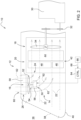
- Fig. 1 shows a schematic representation of an embodiment of a vehicle cooling system distributed over several cooling paths.
- the vehicle cooling system 12 accommodated in an agricultural tractor 10 has a main cooling path 14 and a secondary cooling path 16 branching off upstream from the main cooling path 14, wherein the main cooling path 14 is provided with a main cooling unit 18 for generating a main cooling air flow 22 passing through a first heat exchanger arrangement 20 and the secondary cooling path 16 is provided with a secondary cooling unit 24 located upstream in the main cooling path 14 for generating a secondary cooling air flow 28 passing through a second heat exchanger arrangement 26.
- the main cooling unit 18 comprises an axial fan 34 that can be rotated by a diesel engine 30 of the agricultural tractor 10 via a belt drive 32, by means of which air is sucked in from the outside environment 36 through a front grill 38 of a hood 40 in order to generate the main cooling air flow 22 passing through the first heat exchanger arrangement 20.
- the first heat exchanger arrangement 20, designed as a heat exchanger package 42 contains, among other things, an engine cooler 44, an oil cooler 46 and an air conditioning condenser 48 of a vehicle air conditioning system, wherein these are arranged lying next to one another or one behind the other in the main cooling air flow 22.
- the axial fan 34 is located behind the heat exchanger package 42 with respect to the direction of the main cooling air flow 22, but it can also be arranged in front of it.
- the auxiliary cooling unit 24 is a further axial fan 52 located upstream in an upper edge region 50 of the main cooling air flow 22.
- the further axial fan 52 is assigned a separate drive 54 in the form of a hydraulic or electric motor 56, which serves to independently generate the auxiliary cooling air flow 28 branching off essentially vertically upwards from the main cooling air flow 22.
- the secondary cooling air flow 28 generated by the additional axial fan 52 is a charge air cooler 58 of the diesel engine 30, which is included in the second heat exchanger arrangement 26, and then exits into the external environment 36 at an upper side 60 of the engine hood 40 of the agricultural tractor 10.
- the additional axial fan 52 is located in front of the heat exchanger package 26 with respect to the direction of the secondary cooling air flow 28, but it can also be arranged behind it.
- the axial fans 34, 52 of both the main cooling unit 18 and the secondary cooling unit 24 are operated in such a way that independent cooling air flows 22, 28 are generated, whereas in a Fig. 2 reproduced second operating mode, only the axial fan 34 of the main cooling unit 18 is in operation.
- the further axial fan 52 of the secondary cooling unit 24 is stationary in the second operating mode or is put into an idle operating state in which it has only a low fan speed in the range of 10 to 15 revolutions per minute, so that due to the pressure conditions prevailing upstream in the main cooling air flow 22 (which lead to the formation of a negative pressure), a passive secondary cooling air flow 62 is caused which passes through the second heat exchanger arrangement 26 in the opposite direction or is sucked in from the external environment 36.
- a control unit 64 coordinates the operation of the cooling units 18, 24 by switching between the two operating modes.
- the first or second operating mode is selected depending on a determination made by the control unit 64.
- the current cooling requirement of the two heat exchanger arrangements 20, 26 is selected, for which purpose the temperature conditions detected by sensors in the respective cooling circuits of the heat exchanger arrangements 20, 26 are related to the outside temperature.
- a corresponding number of temperature sensors 66 are provided for sensory detection of the temperature conditions prevailing in the cooling circuits as well as the outside temperature, the sensor data of which are fed to the control unit 64 via an internal vehicle CAN data bus 68.
- the control unit 64 always prioritizes the Fig. 2 shown second operating mode.
- the first operating mode is selected if the control unit 64 recognizes, on the basis of the cooling requirement determination carried out, that the cooling capacity achievable by generating the passive secondary cooling air flow 62 is not sufficient to reliably cover the cooling requirements of the second heat exchanger arrangement 26.
- the control unit 64 recognizes that the full capacity of the main cooling unit 18 is required to adequately cool the first heat exchanger arrangement 20.
- the determined cooling requirement of the first heat exchanger arrangement 20 is also taken into account by the control unit 64 when selecting the operating mode.
- the intensity of the main cooling air flow 22 is controlled by the control unit 64, if necessary by controlling the main cooling unit 18 in accordance with the setting for the first heat exchanger arrangement. 20 determined cooling requirement is increased.
- the cooling capacity of the main cooling unit 18 it is possible, among other things, to prevent the cooling of the first heat exchanger arrangement 20 from being impaired when the auxiliary cooling unit 24 is taken out of operation or in the idle operating state due to the waste heat of the second heat exchanger arrangement 26 additionally entering the main cooling air flow 22 via the passive auxiliary cooling air flow 62.
Landscapes
- Engineering & Computer Science (AREA)
- Chemical & Material Sciences (AREA)
- Combustion & Propulsion (AREA)
- Mechanical Engineering (AREA)
- General Engineering & Computer Science (AREA)
- Transportation (AREA)
- Cooling, Air Intake And Gas Exhaust, And Fuel Tank Arrangements In Propulsion Units (AREA)
Abstract
Description
- Die Erfindung betrifft ein Verfahren zum Betreiben eines Fahrzeugkühlsystems, das einen Hauptkühlpfad sowie einen am Hauptkühlpfad stromaufwärts abzweigenden Nebenkühlpfad aufweist, wobei dem Hauptkühlpfad ein Hauptkühlaggregat zur Erzeugung eines durch eine erste Wärmetauscheranordnung hindurchtretenden Hauptkühlluftstroms und dem Nebenkühlpfad ein stromaufwärts im Hauptkühlpfad liegendes Nebenkühlaggregat zur Erzeugung eines durch eine zweite Wärmetauscheranordnung hindurchtretenden Nebenkühlluftstroms zugeordnet ist.
- Ein solches auf mehrere Kühlpfade verteiltes Fahrzeugkühlsystem findet beispielsweise bei landwirtschaftlichen Traktoren des Herstellers John Deere Verwendung. Dieses umfasst einen von einem Dieselmotor über einen Riementrieb in Drehung versetzbaren Axiallüfter, mittels dessen Luft aus der Außenumgebung durch einen Frontgrill einer Motorhaube angesaugt wird, um einen durch ein Wärmetauscherpaket hindurchtretenden Hauptkühlluftstrom zu erzeugen. Das Wärmetauscherpaket enthält unter anderem einen Motorkühler, einen Ölkühler und einen Klimakondensator einer Fahrzeugklimaanlage, wobei diese im Hauptkühlluftstrom liegend nebeneinander bzw. hintereinander angeordnet sind. Stromaufwärts in einem oberen Randbereich des Hauptkühlluftstroms befindet sich ein weiterer Axiallüfter. Dem weiteren Axiallüfter ist ein separater Antrieb in Gestalt eines hydraulischen oder elektrischen Motors zugeordnet, der der unabhängigen Erzeugung eines im Wesentlichen senkrecht nach oben aus dem Hauptkühlluftstrom abzweigenden Nebenkühlluftstroms dient. Der solchermaßen erzeugte Nebenkühlluftstrom wird durch einen Ladeluftkühler des Dieselmotors geleitet und tritt anschließend an einer Oberseite der Motorhaube des landwirtschaftlichen Traktors in die Außenumgebung aus.
- Das bekannte Fahrzeugkühlsystem weist die Eigenschaft auf, dass der Betrieb der beiden Axiallüfter mit jeweils separaten Antrieben vor allem bei mäßigem Kühlbedarf im Niederlastbereich des landwirtschaftlichen Traktors vergleichsweise ineffizient ist.
- Aufgabe der vorliegenden Erfindung ist es daher, ein Verfahren der eingangs genannten Art hinsichtlich eines energieeffizienten Betriebs eines auf mehrere Kühlpfade verteilten Fahrzeugkühlsystems zu optimieren.
- Diese Aufgabe wird durch ein Verfahren zum Betreiben eines Fahrzeugkühlsystems mit den Merkmalen des Patentanspruchs 1 gelöst.
- Bei einem Verfahren zum Betreiben eines Fahrzeugkühlsystems weist das Fahrzeugkühlsystem einen Hauptkühlpfad sowie einen am Hauptkühlpfad stromaufwärts abzweigenden Nebenkühlpfad auf, wobei dem Hauptkühlpfad ein Hauptkühlaggregat zur Erzeugung eines durch eine erste Wärmetauscheranordnung hindurchtretenden Hauptkühlluftstroms und dem Nebenkühlpfad ein stromaufwärts im Hauptkühlpfad liegendes Nebenkühlaggregat zur Erzeugung eines durch eine zweite Wärmetauscheranordnung hindurchtretenden Nebenkühlluftstroms zugeordnet ist. Hierbei wird von einer Kontrolleinheit in einem ersten Betriebsmodus sowohl das Hauptkühlaggregat wie auch das Nebenkühlaggregat betrieben, um voneinander unabhängige Kühlluftströme zu erzeugen, wohingegen von der Kontrolleinheit in einem zweiten Betriebsmodus ausschließlich das Hauptkühlaggregat betrieben bzw. das Nebenkühlaggregat in einen Leerlaufbetriebszustand derart versetzt wird, sodass aufgrund der stromaufwärts im Hauptkühlluftstrom herrschenden Druckverhältnisse ein durch die zweite Wärmetauscheranordnung hindurchtretender passiver Nebenkühlluftstrom hervorgerufen wird.
- Der erste Betriebsmodus entspricht hierbei einem konventionellen Betrieb der beiden Kühlaggregate mit aktiver Erzeugung sowohl des Haupt- wie auch des Nebenkühlluftstroms, wohingegen im zweiten Betriebsmodus das Nebenkühlaggregat gezielt außer Betrieb gesetzt ist bzw. sich in einem Leerlaufbetriebszustand befindet, sodass eine Leistungsaufnahme im Wesentlichen auf den Betrieb des Hauptkühlaggregats beschränkt ist. Dies trägt Umständen Rechnung, in denen der Kühlbedarf der zweiten Wärmetauscheranordnung so gering ist, dass die Erzeugung eines durch den zweiten Wärmetauscher in umgekehrter Richtung hindurchtretenden passiven Nebenkühlluftstroms für die Zwecke einer ausreichenden Wärmeabfuhr genügt. Durch bedarfsgerechte Auswahl des ersten oder zweiten Betriebsmodus lässt sich daher das verteilte Fahrzeugkühlsystem besonders energieeffizient betreiben.
- Die Kühlaggregate umfassen typischerweise jeweils einen Axiallüfter, der im Falle des Hauptkühlaggregats über einen Riementrieb eines Dieselmotors des landwirtschaftlichen Traktors und im Falle des Nebenkühlaggregats mittels eines separaten hydraulischen oder elektrischen Motors in Drehung versetzt wird.
- Für den im zweiten Betriebsmodus vorgesehenen Leerlaufbetriebszustand bedeutet dies, dass typischerweise eine Lüfterdrehzahl im Bereich von 10 bis 15 Umdrehungen pro Minute gewählt wird. Die Wahl einer solch geringen Lüfterdrehzahl stellt sicher, dass der passive Nebenkühlluftstrom im Leerlaufbetriebszustand unbeeinflusst bleibt, es jedoch aufgrund der sich drehenden Lüfterflügel des Axiallüfters ersichtlich ist, dass sich das Fahrzeugkühlsystem gerade in Betrieb befindet und daher insbesondere bei geöffneter Motorhaube ein potentielles Verletzungsrisiko birgt.
- Der Vollständigkeit halber sei angemerkt, dass der Begriff des "Kühlpfads" vorliegend abstrakt verwendet wird und den für den Verlauf des jeweiligen Kühlluftstroms vorgesehenen bzw. vorgegebenen Weg bezeichnet, ungeachtet dessen, ob ein derartiger Kühlluftstrom gerade vorhanden ist oder nicht.
- Vorteilhafte Weiterbildungen des erfindungsgemäßen Verfahrens gehen aus den Unteransprüchen hervor.
- Vorzugsweise wird der erste oder zweite Betriebsmodus in Abhängigkeit einer von der Kontrolleinheit durchgeführten Ermittlung des aktuellen Kühlbedarfs der zweiten Wärmetauscheranordnung ausgewählt.
- Aus Gründen der Energieeffizienz erfolgt seitens der Kontrolleinheit stets eine Priorisierung des zweiten Betriebsmodus. Abweichend davon wird jedoch der erste Betriebsmodus ausgewählt, wenn die Kontrolleinheit auf Grundlage der durchgeführten Kühlbedarfsermittlung erkennt, dass die durch Erzeugung des passiven Nebenkühlluftstroms erzielbare Kühlleistung nicht genügt, um den Kühlbedarf der zweiten Wärmetauscheranordnung verlässlich abzudecken. Gleiches gilt, wenn von der Kontrolleinheit erkannt wird, dass die volle Leistung des Hauptkühlaggregats zur ausreichenden Kühlung der ersten Wärmetauscheranordnung erforderlich ist.
- Insofern wird also bei der Auswahl des Betriebsmodus von der Kontrolleinheit der ermittelte Kühlbedarf der ersten Wärmetauscheranordnung mitberücksichtigt.
- Um den aktuellen Kühlbedarf zu ermitteln, können von der Kontrolleinheit die in jeweiligen Kühlkreisläufen der Wärmetauscheranordnungen sensorisch erfassten Temperaturverhältnisse in Beziehung zur Außentemperatur gesetzt werden. Zur sensorischen Erfassung der in den Kühlkreisläufen herrschenden Temperaturverhältnisse sowie der Außentemperatur ist eine entsprechende Anzahl von Temperatursensoren vorhanden, deren Sensordaten der Kontrolleinheit über einen fahrzeuginternen CAN-Datenbus oder eine vergleichbare Datenübertragungsschnittstelle zugeführt werden.
- Weiterhin besteht die Möglichkeit, dass im zweiten Betriebsmodus die Intensität des Hauptkühlluftstroms von der Kontrolleinheit durch Ansteuerung des Hauptkühlaggregats insbesondere nach Maßgabe eines für die erste Wärmetauscheranordnung ermittelten Kühlbedarfs erhöht wird. Durch entsprechende Anhebung der Kühlleistung des Hauptkühlaggregats lässt sich unter anderem verhindern, dass bei Außerbetriebnahme bzw. im Leerlaufbetriebszustand des Nebenkühlaggregats die Kühlung der ersten Wärmetauscheranordnung aufgrund der über den passiven Nebenkühlluftstrom in den Hauptkühlluftstrom zusätzlich eintretenden Abwärme der zweiten Wärmetauscheranordnung beeinträchtigt wird.
- Das erfindungsgemäße Verfahren zum Betreiben eines Fahrzeugkühlsystems wird im Folgenden anhand der Zeichnungen näher beschrieben. Dabei beziehen sich identische Bezugszeichen auf übereinstimmende oder bezüglich ihrer Funktion vergleichbare Komponenten. Es zeigen:
- Fig. 1
- ein schematisch dargestelltes Ausführungsbeispiel eines auf mehrere Kühlpfade verteilten Fahrzeugkühlsystems eines landwirtschaftlichen Traktors in einem ersten Betriebsmodus, und
- Fig. 2
- das in
Fig. 1 wiedergegebene Fahrzeugkühlsystem in einem zweiten Betriebsmodus. -
Fig. 1 zeigt in schematischer Darstellung ein Ausführungsbeispiel eines auf mehrere Kühlpfade verteilten Fahrzeugkühlsystems. - Das in einem nicht näher abgebildeten landwirtschaftlichen Traktor 10 untergebrachte Fahrzeugkühlsystem 12 weist einen Hauptkühlpfad 14 sowie einen am Hauptkühlpfad 14 stromaufwärts abzweigenden Nebenkühlpfad 16 auf, wobei dem Hauptkühlpfad 14 ein Hauptkühlaggregat 18 zur Erzeugung eines durch eine erste Wärmetauscheranordnung 20 hindurchtretenden Hauptkühlluftstroms 22 und dem Nebenkühlpfad 16 ein stromaufwärts im Hauptkühlpfad 14 liegendes Nebenkühlaggregat 24 zur Erzeugung eines durch eine zweite Wärmetauscheranordnung 26 hindurchtretenden Nebenkühlluftstroms 28 zugeordnet ist.
- Beispielsgemäß umfasst das Hauptkühlaggregat 18 einen von einem Dieselmotor 30 des landwirtschaftlichen Traktors 10 über einen Riementrieb 32 in Drehung versetzbaren Axiallüfter 34, mittels dessen Luft aus der Außenumgebung 36 durch einen Frontgrill 38 einer Motorhaube 40 angesaugt wird, um den durch die erste Wärmetauscheranordnung 20 hindurchtretenden Hauptkühlluftstrom 22 zu erzeugen. Die als Wärmetauscherpaket 42 ausgebildete erste Wärmetauscheranordnung 20 enthält unter anderem einen Motorkühler 44, einen Ölkühler 46 und einen Klimakondensator 48 einer Fahrzeugklimaanlage, wobei diese im Hauptkühlluftstrom 22 liegend nebeneinander bzw. hintereinander angeordnet sind.
- Beispielsgemäß befindet sich der Axiallüfter 34 bezüglich der Richtung des Hauptkühlluftstroms 22 hinter dem Wärmetauscherpaket 42, dieser kann jedoch auch davor angeordnet sein.
- Bei dem Nebenkühlaggregat 24 handelt es sich um einen stromaufwärts in einem oberen Randbereich 50 des Hauptkühlluftstroms 22 liegenden weiteren Axiallüfter 52. Dem weiteren Axiallüfter 52 ist ein separater Antrieb 54 in Gestalt eines hydraulischen oder elektrischen Motors 56 zugeordnet, der der unabhängigen Erzeugung des im Wesentlichen senkrecht nach oben aus dem Hauptkühlluftstrom 22 abzweigenden Nebenkühlluftstroms 28 dient. Entsprechend einem in
Fig. 1 wiedergegebenen ersten Betriebsmodus des Fahrzeugkühlsystems 12 wird der mittels des weiteren Axiallüfters 52 erzeugte Nebenkühlluftstrom 28 durch einen von der zweiten Wärmetauscheranordnung 26 umfassten Ladeluftkühler 58 des Dieselmotors 30 geleitet und tritt anschließend an einer Oberseite 60 der Motorhaube 40 des landwirtschaftlichen Traktors 10 in die Außenumgebung 36 aus. - Vorliegend befindet sich der weitere Axiallüfter 52 bezüglich der Richtung des Nebenkühlluftstroms 28 vor dem Wärmetauscherpaket 26, dieser kann jedoch auch dahinter angeordnet sein.
- Genauer gesagt werden im ersten Betriebsmodus die Axiallüfter 34, 52 sowohl des Hauptkühlaggregats 18 wie auch des Nebenkühlaggregats 24 derart betrieben, dass voneinander unabhängige Kühlluftströme 22, 28 erzeugt werden, wohingegen in einem in
Fig. 2 wiedergegebenen zweiten Betriebsmodus sich ausschließlich der Axiallüfter 34 des Hauptkühlaggregats 18 in Betrieb befindet. Der weitere Axiallüfter 52 des Nebenkühlaggregats 24 steht im zweiten Betriebsmodus still bzw. wird in einen Leerlaufbetriebszustand versetzt, in dem dieser eine lediglich geringe Lüfterdrehzahl im Bereich von 10 bis 15 Umdrehungen pro Minute aufweist, sodass aufgrund der stromaufwärts im Hauptkühlluftstrom 22 herrschenden Druckverhältnisse (die zur Ausbildung eines Unterdrucks führen) ein durch die zweite Wärmetauscheranordnung 26 in umgekehrter Richtung hindurchtretender bzw. aus der Außenumgebung 36 angesaugter passiver Nebenkühlluftstrom 62 hervorgerufen wird. - Eine Kontrolleinheit 64 koordiniert den Betrieb der Kühlaggregate 18, 24 durch Umschaltung zwischen den beiden Betriebsmodi. Hierbei wird der erste oder zweite Betriebsmodus in Abhängigkeit einer von der Kontrolleinheit 64 durchgeführten Ermittlung des aktuellen Kühlbedarfs der beiden Wärmetauscheranordnungen 20, 26 ausgewählt, wozu die in jeweiligen Kühlkreisläufen der Wärmetauscheranordnungen 20, 26 sensorisch erfassten Temperaturverhältnisse in Beziehung zur Außentemperatur gesetzt werden.
- Zur sensorischen Erfassung der in den Kühlkreisläufen herrschenden Temperaturverhältnisse sowie der Außentemperatur ist eine entsprechende Anzahl von Temperatursensoren 66 vorhanden, deren Sensordaten der Kontrolleinheit 64 über einen fahrzeuginternen CAN-Datenbus 68 zugeführt werden.
- Aus Gründen der Energieeffizienz erfolgt seitens der Kontrolleinheit 64 stets eine Priorisierung des in
Fig. 2 gezeigten zweiten Betriebsmodus. Abweichend davon wird jedoch der erste Betriebsmodus ausgewählt, wenn die Kontrolleinheit 64 auf Grundlage der durchgeführten Kühlbedarfsermittlung erkennt, dass die durch Erzeugung des passiven Nebenkühlluftstroms 62 erzielbare Kühlleistung nicht genügt, um den Kühlbedarf der zweiten Wärmetauscheranordnung 26 verlässlich abzudecken. Gleiches gilt, wenn von der Kontrolleinheit 64 erkannt wird, dass die volle Leistung des Hauptkühlaggregats 18 zur ausreichenden Kühlung der ersten Wärmetauscheranordnung 20 erforderlich ist. Insofern wird also bei der Auswahl des Betriebsmodus von der Kontrolleinheit 64 der ermittelte Kühlbedarf der ersten Wärmetauscheranordnung 20 mitberücksichtigt. - Erfolgt eine Umschaltung in den zweiten Betriebsmodus, so wird die Intensität des Hauptkühlluftstroms 22 von der Kontrolleinheit 64 gegebenenfalls durch Ansteuerung des Hauptkühlaggregats 18 nach Maßgabe des für die erste Wärmetauscheranordnung 20 ermittelten Kühlbedarfs erhöht. Durch entsprechende Anhebung der Kühlleistung des Hauptkühlaggregats 18 lässt sich unter anderem verhindern, dass bei Außerbetriebnahme bzw. im Leerlaufbetriebszustand des Nebenkühlaggregats 24 die Kühlung der ersten Wärmetauscheranordnung 20 aufgrund der über den passiven Nebenkühlluftstrom 62 in den Hauptkühlluftstrom 22 zusätzlich eintretenden Abwärme der zweiten Wärmetauscheranordnung 26 beeinträchtigt wird.
Claims (5)
- Verfahren zum Betreiben eines Fahrzeugkühlsystems, umfassend einen Hauptkühlpfad (14) sowie einen am Hauptkühlpfad (14) stromaufwärts abzweigenden Nebenkühlpfad (16), wobei dem Hauptkühlpfad (14) ein Hauptkühlaggregat (18) zur Erzeugung eines durch eine erste Wärmetauscheranordnung (20) hindurchtretenden Hauptkühlluftstroms (22) und dem Nebenkühlpfad (16) ein stromaufwärts im Hauptkühlpfad (14) liegendes Nebenkühlaggregat (24) zur Erzeugung eines durch eine zweite Wärmetauscheranordnung (26) hindurchtretenden Nebenkühlluftstroms (28) zugeordnet ist, dadurch gekennzeichnet, dass von einer Kontrolleinheit (64) in einem ersten Betriebsmodus sowohl das Hauptkühlaggregat (18) wie auch das Nebenkühlaggregat (24) betrieben wird, um voneinander unabhängige Kühlluftströme (22, 28) zu erzeugen, wohingegen von der Kontrolleinheit (64) in einem zweiten Betriebsmodus ausschließlich das Hauptkühlaggregat (18) betrieben bzw. das Nebenkühlaggregat (24) in einen Leerlaufbetriebszustand derart versetzt wird, sodass aufgrund der stromaufwärts im Hauptkühlluftstrom (22) herrschenden Druckverhältnisse ein durch die zweite Wärmetauscheranordnung (26) hindurchtretender passiver Nebenkühlluftstrom (62) hervorgerufen wird.
- Verfahren nach Anspruch 1, dadurch gekennzeichnet, dass der erste oder zweite Betriebsmodus in Abhängigkeit einer von der Kontrolleinheit (64) durchgeführten Ermittlung des aktuellen Kühlbedarfs der zweiten Wärmetauscheranordnung (26) ausgewählt wird.
- Verfahren nach Anspruch 2, dadurch gekennzeichnet, dass bei der Auswahl des Betriebsmodus von der Kontrolleinheit (64) ein ermittelter Kühlbedarf der ersten Wärmetauscheranordnung (20) mitberücksichtigt wird.
- Verfahren nach Anspruch 2 oder 3, dadurch gekennzeichnet, dass zur Ermittlung des aktuellen Kühlbedarfs von der Kontrolleinheit (64) die in jeweiligen Kühlkreisläufen der Wärmetauscheranordnungen (20, 26) sensorisch erfassten Temperaturverhältnisse in Beziehung zur Außentemperatur gesetzt werden.
- Verfahren nach wenigstens einem der vorhergehenden Ansprüche, dadurch gekennzeichnet, dass im zweiten Betriebsmodus die Intensität des Hauptkühlluftstroms (22) von der Kontrolleinheit (64) durch Ansteuerung des Hauptkühlaggregats (18) erhöht wird.
Applications Claiming Priority (1)
| Application Number | Priority Date | Filing Date | Title |
|---|---|---|---|
| DE102023105066.4A DE102023105066A1 (de) | 2023-03-01 | 2023-03-01 | Verfahren zum Betreiben eines Fahrzeugkühlsystems |
Publications (2)
| Publication Number | Publication Date |
|---|---|
| EP4438865A1 true EP4438865A1 (de) | 2024-10-02 |
| EP4438865B1 EP4438865B1 (de) | 2025-12-31 |
Family
ID=89767280
Family Applications (1)
| Application Number | Title | Priority Date | Filing Date |
|---|---|---|---|
| EP24154374.3A Active EP4438865B1 (de) | 2023-03-01 | 2024-01-29 | Verfahren zum betreiben eines fahrzeugkühlsystems |
Country Status (3)
| Country | Link |
|---|---|
| US (1) | US12497915B2 (de) |
| EP (1) | EP4438865B1 (de) |
| DE (1) | DE102023105066A1 (de) |
Families Citing this family (1)
| Publication number | Priority date | Publication date | Assignee | Title |
|---|---|---|---|---|
| DE102023105066A1 (de) * | 2023-03-01 | 2024-09-05 | Deere & Company | Verfahren zum Betreiben eines Fahrzeugkühlsystems |
Citations (6)
| Publication number | Priority date | Publication date | Assignee | Title |
|---|---|---|---|---|
| JPH02133233A (ja) * | 1988-11-11 | 1990-05-22 | Kubota Ltd | エンジンの冷却風防塵吸風装置 |
| EP2757233A1 (de) * | 2013-01-18 | 2014-07-23 | Deere & Company | Kühlungsanordnung für ein Kraftfahrzeug |
| DE102014208545A1 (de) * | 2014-05-07 | 2015-11-12 | Deere & Company | Vorrichtung zur Kühlung von Ladeluft |
| FR3093303A1 (fr) * | 2019-02-28 | 2020-09-04 | Valeo Systemes Thermiques | Vehicule automobile comprenant un systeme de regulation thermique |
| DE102019204468A1 (de) * | 2019-03-29 | 2020-10-01 | Deere & Company | Traktor mit Ladeluftkühlung |
| EP4257809A1 (de) * | 2022-03-23 | 2023-10-11 | Deere & Company | Verfahren zum betreiben eines fahrzeugkühlsystems |
Family Cites Families (7)
| Publication number | Priority date | Publication date | Assignee | Title |
|---|---|---|---|---|
| DE19910651A1 (de) * | 1998-03-13 | 1999-09-16 | Denso Corp | Motorkühlvorrichtung |
| SE542203C2 (en) * | 2016-01-15 | 2020-03-10 | Scania Cv Ab | A vehicle with a fan arrangement |
| US10479191B2 (en) * | 2017-12-19 | 2019-11-19 | Cnh Industrial America Llc | Cooling systems and methods for an agricultural harvester |
| US10823041B2 (en) * | 2017-12-19 | 2020-11-03 | Pratt & Whitney Canada Corp. | Engine assembly with plenum and remote fan |
| JP7248395B2 (ja) * | 2018-08-31 | 2023-03-29 | トヨタ自動車株式会社 | 車両用冷却装置 |
| DE102021127498A1 (de) * | 2021-10-22 | 2023-04-27 | Cabero Beteiligungs-Gmbh | Kühlsystem |
| DE102023105066A1 (de) * | 2023-03-01 | 2024-09-05 | Deere & Company | Verfahren zum Betreiben eines Fahrzeugkühlsystems |
-
2023
- 2023-03-01 DE DE102023105066.4A patent/DE102023105066A1/de active Pending
-
2024
- 2024-01-29 EP EP24154374.3A patent/EP4438865B1/de active Active
- 2024-02-19 US US18/444,919 patent/US12497915B2/en active Active
Patent Citations (6)
| Publication number | Priority date | Publication date | Assignee | Title |
|---|---|---|---|---|
| JPH02133233A (ja) * | 1988-11-11 | 1990-05-22 | Kubota Ltd | エンジンの冷却風防塵吸風装置 |
| EP2757233A1 (de) * | 2013-01-18 | 2014-07-23 | Deere & Company | Kühlungsanordnung für ein Kraftfahrzeug |
| DE102014208545A1 (de) * | 2014-05-07 | 2015-11-12 | Deere & Company | Vorrichtung zur Kühlung von Ladeluft |
| FR3093303A1 (fr) * | 2019-02-28 | 2020-09-04 | Valeo Systemes Thermiques | Vehicule automobile comprenant un systeme de regulation thermique |
| DE102019204468A1 (de) * | 2019-03-29 | 2020-10-01 | Deere & Company | Traktor mit Ladeluftkühlung |
| EP4257809A1 (de) * | 2022-03-23 | 2023-10-11 | Deere & Company | Verfahren zum betreiben eines fahrzeugkühlsystems |
Also Published As
| Publication number | Publication date |
|---|---|
| US20240295187A1 (en) | 2024-09-05 |
| US12497915B2 (en) | 2025-12-16 |
| EP4438865B1 (de) | 2025-12-31 |
| DE102023105066A1 (de) | 2024-09-05 |
Similar Documents
| Publication | Publication Date | Title |
|---|---|---|
| EP0638712B1 (de) | Kühlmittelkreislauf | |
| DE4109498B4 (de) | Vorrichtung und Verfahren zur Regelung der Temperatur einer Brennkraftmaschine | |
| EP0389502B1 (de) | Vorrichtung und verfahren zur motorkühlung | |
| DE112014000209T5 (de) | Baufahrzeug | |
| DE102018207004A1 (de) | System zum Kühlen einer Elektromaschine | |
| DE102012204492B4 (de) | Verfahren zum Überprüfen der Funktionstüchtigkeit von Hydraulikkomponenten im Kühlkreislauf eines Kraftfahrzeuges | |
| EP3088235A1 (de) | Energiemanagementsystem für eine landwirtschaftliche fahrzeuganordnung | |
| DE102021116290A1 (de) | Abwärmeabfangverfahren und -system für eine arbeitsmaschine | |
| DE102017217685A1 (de) | Anordnung zur Temperierung einer Batterie und weiterer elektrischer Komponenten eines Fahrzeugs, Fahrzeug sowie Verfahren zur Steuerung der Anordnung | |
| DE102011052754B4 (de) | Antriebseinheit mit zwei koppelbaren Kühlkreisläufen und Verfahren | |
| WO2021052785A1 (de) | Verfahren zur überwachung eines ölflusses in einem ölkühlkreis | |
| DE102013214560A1 (de) | Detektieren einer blockierung einer luftströmung durch eine fahrzeugtraktionsbatterie | |
| EP4438865A1 (de) | Verfahren zum betreiben eines fahrzeugkühlsystems | |
| EP4031755A1 (de) | Thermomanagementsystem und fahrzeug | |
| DE112020000329T5 (de) | Ein verteiltes kühlsystem für eine arbeitsmaschine | |
| DE112016006612T5 (de) | Kühlungssystem für eine Hochspannungsausstattung für Fahrzeuge mit Elektroantrieb | |
| DE102006041819A1 (de) | Steuerung zum selektiven Steuern des Ausgangsstroms und einer Ausgangsspannung eines Elektroerzeugers | |
| DE102020133283A1 (de) | Kühlsystem zum Kühlen einer steuerbaren Wärmequelle | |
| DE102023101659A1 (de) | Hydrauliksystem für eine landwirtschaftliche Arbeitsmaschine | |
| DE102024132538A1 (de) | Erwärmungs-ölmanagementstrategie | |
| DE102015008006B3 (de) | Verfahren zum Begrenzen einer Performanz eines Steuergeräts in einem Kraftfahrzeug und Kraftfahrzeug | |
| DE102013225487B4 (de) | Verfahren zum Steuern der Temperatur eines Steuergeräts einer Kompressoranordnung für eine Klimaanlage in einem Fahrzeug | |
| DE102023129471A1 (de) | Verfahren zum Steuern eines Betriebs eines Fahrzeugkühlsystems, Computerprogramm, computerlesbares Medium, Steueranordnung, Fahrzeugkühlsystem, und Fahrzeug | |
| DE102008041800B4 (de) | Kühleinrichtung für ein Kraftfahrzeug | |
| DE102021125741A1 (de) | Kühlsystem eines Kraftfahrzeugs und Verfahren für ein Kühlsystem eines Kraftfahrzeugs |
Legal Events
| Date | Code | Title | Description |
|---|---|---|---|
| PUAI | Public reference made under article 153(3) epc to a published international application that has entered the european phase |
Free format text: ORIGINAL CODE: 0009012 |
|
| STAA | Information on the status of an ep patent application or granted ep patent |
Free format text: STATUS: THE APPLICATION HAS BEEN PUBLISHED |
|
| AK | Designated contracting states |
Kind code of ref document: A1 Designated state(s): AL AT BE BG CH CY CZ DE DK EE ES FI FR GB GR HR HU IE IS IT LI LT LU LV MC ME MK MT NL NO PL PT RO RS SE SI SK SM TR |
|
| STAA | Information on the status of an ep patent application or granted ep patent |
Free format text: STATUS: REQUEST FOR EXAMINATION WAS MADE |
|
| 17P | Request for examination filed |
Effective date: 20250402 |
|
| GRAP | Despatch of communication of intention to grant a patent |
Free format text: ORIGINAL CODE: EPIDOSNIGR1 |
|
| STAA | Information on the status of an ep patent application or granted ep patent |
Free format text: STATUS: GRANT OF PATENT IS INTENDED |
|
| RIC1 | Information provided on ipc code assigned before grant |
Ipc: F01P 3/18 20060101AFI20250829BHEP Ipc: B60K 11/02 20060101ALI20250829BHEP Ipc: F01P 5/06 20060101ALI20250829BHEP Ipc: F01P 7/04 20060101ALI20250829BHEP Ipc: F01P 7/08 20060101ALI20250829BHEP Ipc: F01P 11/10 20060101ALI20250829BHEP Ipc: F01P 5/10 20060101ALN20250829BHEP |
|
| INTG | Intention to grant announced |
Effective date: 20250919 |
|
| GRAS | Grant fee paid |
Free format text: ORIGINAL CODE: EPIDOSNIGR3 |
|
| GRAA | (expected) grant |
Free format text: ORIGINAL CODE: 0009210 |
|
| STAA | Information on the status of an ep patent application or granted ep patent |
Free format text: STATUS: THE PATENT HAS BEEN GRANTED |
|
| AK | Designated contracting states |
Kind code of ref document: B1 Designated state(s): AL AT BE BG CH CY CZ DE DK EE ES FI FR GB GR HR HU IE IS IT LI LT LU LV MC ME MK MT NL NO PL PT RO RS SE SI SK SM TR |
|
| REG | Reference to a national code |
Ref country code: CH Ref legal event code: F10 Free format text: ST27 STATUS EVENT CODE: U-0-0-F10-F00 (AS PROVIDED BY THE NATIONAL OFFICE) Effective date: 20251231 Ref country code: GB Ref legal event code: FG4D Free format text: NOT ENGLISH |
|
| REG | Reference to a national code |
Ref country code: DE Ref legal event code: R096 Ref document number: 502024000552 Country of ref document: DE |
|
| REG | Reference to a national code |
Ref country code: IE Ref legal event code: FG4D Free format text: LANGUAGE OF EP DOCUMENT: GERMAN |
|
| REG | Reference to a national code |
Ref country code: LT Ref legal event code: MG9D |
|
| PG25 | Lapsed in a contracting state [announced via postgrant information from national office to epo] |
Ref country code: NO Free format text: LAPSE BECAUSE OF FAILURE TO SUBMIT A TRANSLATION OF THE DESCRIPTION OR TO PAY THE FEE WITHIN THE PRESCRIBED TIME-LIMIT Effective date: 20260331 |
|
| PGFP | Annual fee paid to national office [announced via postgrant information from national office to epo] |
Ref country code: DE Payment date: 20260128 Year of fee payment: 3 |
|
| PG25 | Lapsed in a contracting state [announced via postgrant information from national office to epo] |
Ref country code: FI Free format text: LAPSE BECAUSE OF FAILURE TO SUBMIT A TRANSLATION OF THE DESCRIPTION OR TO PAY THE FEE WITHIN THE PRESCRIBED TIME-LIMIT Effective date: 20251231 Ref country code: HR Free format text: LAPSE BECAUSE OF FAILURE TO SUBMIT A TRANSLATION OF THE DESCRIPTION OR TO PAY THE FEE WITHIN THE PRESCRIBED TIME-LIMIT Effective date: 20251231 |
|
| PGFP | Annual fee paid to national office [announced via postgrant information from national office to epo] |
Ref country code: AT Payment date: 20260301 Year of fee payment: 3 |
|
| PGFP | Annual fee paid to national office [announced via postgrant information from national office to epo] |
Ref country code: IT Payment date: 20260131 Year of fee payment: 3 |
|
| PG25 | Lapsed in a contracting state [announced via postgrant information from national office to epo] |
Ref country code: RS Free format text: LAPSE BECAUSE OF FAILURE TO SUBMIT A TRANSLATION OF THE DESCRIPTION OR TO PAY THE FEE WITHIN THE PRESCRIBED TIME-LIMIT Effective date: 20260331 |
|
| PGFP | Annual fee paid to national office [announced via postgrant information from national office to epo] |
Ref country code: FR Payment date: 20260126 Year of fee payment: 3 |
|
| PG25 | Lapsed in a contracting state [announced via postgrant information from national office to epo] |
Ref country code: LV Free format text: LAPSE BECAUSE OF FAILURE TO SUBMIT A TRANSLATION OF THE DESCRIPTION OR TO PAY THE FEE WITHIN THE PRESCRIBED TIME-LIMIT Effective date: 20251231 |