EP4438352A2 - Verfahren zur steuerung eines aufhängungssystems, steuerungssystem und aufhängungssteuerungssystem - Google Patents
Verfahren zur steuerung eines aufhängungssystems, steuerungssystem und aufhängungssteuerungssystem Download PDFInfo
- Publication number
- EP4438352A2 EP4438352A2 EP23211799.4A EP23211799A EP4438352A2 EP 4438352 A2 EP4438352 A2 EP 4438352A2 EP 23211799 A EP23211799 A EP 23211799A EP 4438352 A2 EP4438352 A2 EP 4438352A2
- Authority
- EP
- European Patent Office
- Prior art keywords
- signals
- group
- suspension
- signal
- vehicle
- Prior art date
- Legal status (The legal status is an assumption and is not a legal conclusion. Google has not performed a legal analysis and makes no representation as to the accuracy of the status listed.)
- Pending
Links
Images


Classifications
-
- B—PERFORMING OPERATIONS; TRANSPORTING
- B60—VEHICLES IN GENERAL
- B60G—VEHICLE SUSPENSION ARRANGEMENTS
- B60G17/00—Resilient suspensions having means for adjusting the spring or vibration-damper characteristics, for regulating the distance between a supporting surface and a sprung part of vehicle or for locking suspension during use to meet varying vehicular or surface conditions, e.g. due to speed or load
- B60G17/015—Resilient suspensions having means for adjusting the spring or vibration-damper characteristics, for regulating the distance between a supporting surface and a sprung part of vehicle or for locking suspension during use to meet varying vehicular or surface conditions, e.g. due to speed or load the regulating means comprising electric or electronic elements
- B60G17/016—Resilient suspensions having means for adjusting the spring or vibration-damper characteristics, for regulating the distance between a supporting surface and a sprung part of vehicle or for locking suspension during use to meet varying vehicular or surface conditions, e.g. due to speed or load the regulating means comprising electric or electronic elements characterised by their responsiveness, when the vehicle is travelling, to specific motion, a specific condition, or driver input
- B60G17/0164—Resilient suspensions having means for adjusting the spring or vibration-damper characteristics, for regulating the distance between a supporting surface and a sprung part of vehicle or for locking suspension during use to meet varying vehicular or surface conditions, e.g. due to speed or load the regulating means comprising electric or electronic elements characterised by their responsiveness, when the vehicle is travelling, to specific motion, a specific condition, or driver input mainly during accelerating or braking
-
- B—PERFORMING OPERATIONS; TRANSPORTING
- B60—VEHICLES IN GENERAL
- B60G—VEHICLE SUSPENSION ARRANGEMENTS
- B60G17/00—Resilient suspensions having means for adjusting the spring or vibration-damper characteristics, for regulating the distance between a supporting surface and a sprung part of vehicle or for locking suspension during use to meet varying vehicular or surface conditions, e.g. due to speed or load
- B60G17/015—Resilient suspensions having means for adjusting the spring or vibration-damper characteristics, for regulating the distance between a supporting surface and a sprung part of vehicle or for locking suspension during use to meet varying vehicular or surface conditions, e.g. due to speed or load the regulating means comprising electric or electronic elements
- B60G17/016—Resilient suspensions having means for adjusting the spring or vibration-damper characteristics, for regulating the distance between a supporting surface and a sprung part of vehicle or for locking suspension during use to meet varying vehicular or surface conditions, e.g. due to speed or load the regulating means comprising electric or electronic elements characterised by their responsiveness, when the vehicle is travelling, to specific motion, a specific condition, or driver input
- B60G17/0165—Resilient suspensions having means for adjusting the spring or vibration-damper characteristics, for regulating the distance between a supporting surface and a sprung part of vehicle or for locking suspension during use to meet varying vehicular or surface conditions, e.g. due to speed or load the regulating means comprising electric or electronic elements characterised by their responsiveness, when the vehicle is travelling, to specific motion, a specific condition, or driver input to an external condition, e.g. rough road surface, side wind
-
- B—PERFORMING OPERATIONS; TRANSPORTING
- B60—VEHICLES IN GENERAL
- B60G—VEHICLE SUSPENSION ARRANGEMENTS
- B60G17/00—Resilient suspensions having means for adjusting the spring or vibration-damper characteristics, for regulating the distance between a supporting surface and a sprung part of vehicle or for locking suspension during use to meet varying vehicular or surface conditions, e.g. due to speed or load
- B60G17/015—Resilient suspensions having means for adjusting the spring or vibration-damper characteristics, for regulating the distance between a supporting surface and a sprung part of vehicle or for locking suspension during use to meet varying vehicular or surface conditions, e.g. due to speed or load the regulating means comprising electric or electronic elements
- B60G17/018—Resilient suspensions having means for adjusting the spring or vibration-damper characteristics, for regulating the distance between a supporting surface and a sprung part of vehicle or for locking suspension during use to meet varying vehicular or surface conditions, e.g. due to speed or load the regulating means comprising electric or electronic elements characterised by the use of a specific signal treatment or control method
- B60G17/0182—Resilient suspensions having means for adjusting the spring or vibration-damper characteristics, for regulating the distance between a supporting surface and a sprung part of vehicle or for locking suspension during use to meet varying vehicular or surface conditions, e.g. due to speed or load the regulating means comprising electric or electronic elements characterised by the use of a specific signal treatment or control method involving parameter estimation, e.g. observer, Kalman filter
-
- B—PERFORMING OPERATIONS; TRANSPORTING
- B60—VEHICLES IN GENERAL
- B60G—VEHICLE SUSPENSION ARRANGEMENTS
- B60G17/00—Resilient suspensions having means for adjusting the spring or vibration-damper characteristics, for regulating the distance between a supporting surface and a sprung part of vehicle or for locking suspension during use to meet varying vehicular or surface conditions, e.g. due to speed or load
- B60G17/015—Resilient suspensions having means for adjusting the spring or vibration-damper characteristics, for regulating the distance between a supporting surface and a sprung part of vehicle or for locking suspension during use to meet varying vehicular or surface conditions, e.g. due to speed or load the regulating means comprising electric or electronic elements
- B60G17/0195—Resilient suspensions having means for adjusting the spring or vibration-damper characteristics, for regulating the distance between a supporting surface and a sprung part of vehicle or for locking suspension during use to meet varying vehicular or surface conditions, e.g. due to speed or load the regulating means comprising electric or electronic elements characterised by the regulation being combined with other vehicle control systems
-
- B—PERFORMING OPERATIONS; TRANSPORTING
- B60—VEHICLES IN GENERAL
- B60R—VEHICLES, VEHICLE FITTINGS, OR VEHICLE PARTS, NOT OTHERWISE PROVIDED FOR
- B60R16/00—Electric or fluid circuits specially adapted for vehicles and not otherwise provided for; Arrangement of elements of electric or fluid circuits specially adapted for vehicles and not otherwise provided for
- B60R16/02—Electric or fluid circuits specially adapted for vehicles and not otherwise provided for; Arrangement of elements of electric or fluid circuits specially adapted for vehicles and not otherwise provided for electric constitutive elements
- B60R16/037—Electric or fluid circuits specially adapted for vehicles and not otherwise provided for; Arrangement of elements of electric or fluid circuits specially adapted for vehicles and not otherwise provided for electric constitutive elements for occupant comfort, e.g. for automatic adjustment of appliances according to personal settings, e.g. seats, mirrors, steering wheel
-
- B—PERFORMING OPERATIONS; TRANSPORTING
- B60—VEHICLES IN GENERAL
- B60T—VEHICLE BRAKE CONTROL SYSTEMS OR PARTS THEREOF; BRAKE CONTROL SYSTEMS OR PARTS THEREOF, IN GENERAL; ARRANGEMENT OF BRAKING ELEMENTS ON VEHICLES IN GENERAL; PORTABLE DEVICES FOR PREVENTING UNWANTED MOVEMENT OF VEHICLES; VEHICLE MODIFICATIONS TO FACILITATE COOLING OF BRAKES
- B60T8/00—Arrangements for adjusting wheel-braking force to meet varying vehicular or ground-surface conditions, e.g. limiting or varying distribution of braking force
- B60T8/17—Using electrical or electronic regulation means to control braking
- B60T8/171—Detecting parameters used in the regulation; Measuring values used in the regulation
-
- B—PERFORMING OPERATIONS; TRANSPORTING
- B60—VEHICLES IN GENERAL
- B60T—VEHICLE BRAKE CONTROL SYSTEMS OR PARTS THEREOF; BRAKE CONTROL SYSTEMS OR PARTS THEREOF, IN GENERAL; ARRANGEMENT OF BRAKING ELEMENTS ON VEHICLES IN GENERAL; PORTABLE DEVICES FOR PREVENTING UNWANTED MOVEMENT OF VEHICLES; VEHICLE MODIFICATIONS TO FACILITATE COOLING OF BRAKES
- B60T8/00—Arrangements for adjusting wheel-braking force to meet varying vehicular or ground-surface conditions, e.g. limiting or varying distribution of braking force
- B60T8/18—Arrangements for adjusting wheel-braking force to meet varying vehicular or ground-surface conditions, e.g. limiting or varying distribution of braking force responsive to vehicle weight or load, e.g. load distribution
-
- B—PERFORMING OPERATIONS; TRANSPORTING
- B60—VEHICLES IN GENERAL
- B60T—VEHICLE BRAKE CONTROL SYSTEMS OR PARTS THEREOF; BRAKE CONTROL SYSTEMS OR PARTS THEREOF, IN GENERAL; ARRANGEMENT OF BRAKING ELEMENTS ON VEHICLES IN GENERAL; PORTABLE DEVICES FOR PREVENTING UNWANTED MOVEMENT OF VEHICLES; VEHICLE MODIFICATIONS TO FACILITATE COOLING OF BRAKES
- B60T8/00—Arrangements for adjusting wheel-braking force to meet varying vehicular or ground-surface conditions, e.g. limiting or varying distribution of braking force
- B60T8/24—Arrangements for adjusting wheel-braking force to meet varying vehicular or ground-surface conditions, e.g. limiting or varying distribution of braking force responsive to vehicle inclination or change of direction, e.g. negotiating bends
- B60T8/245—Longitudinal vehicle inclination
-
- B—PERFORMING OPERATIONS; TRANSPORTING
- B60—VEHICLES IN GENERAL
- B60T—VEHICLE BRAKE CONTROL SYSTEMS OR PARTS THEREOF; BRAKE CONTROL SYSTEMS OR PARTS THEREOF, IN GENERAL; ARRANGEMENT OF BRAKING ELEMENTS ON VEHICLES IN GENERAL; PORTABLE DEVICES FOR PREVENTING UNWANTED MOVEMENT OF VEHICLES; VEHICLE MODIFICATIONS TO FACILITATE COOLING OF BRAKES
- B60T8/00—Arrangements for adjusting wheel-braking force to meet varying vehicular or ground-surface conditions, e.g. limiting or varying distribution of braking force
- B60T8/32—Arrangements for adjusting wheel-braking force to meet varying vehicular or ground-surface conditions, e.g. limiting or varying distribution of braking force responsive to a speed condition, e.g. acceleration or deceleration
-
- F—MECHANICAL ENGINEERING; LIGHTING; HEATING; WEAPONS; BLASTING
- F16—ENGINEERING ELEMENTS AND UNITS; GENERAL MEASURES FOR PRODUCING AND MAINTAINING EFFECTIVE FUNCTIONING OF MACHINES OR INSTALLATIONS; THERMAL INSULATION IN GENERAL
- F16D—COUPLINGS FOR TRANSMITTING ROTATION; CLUTCHES; BRAKES
- F16D63/00—Brakes not otherwise provided for; Brakes combining more than one of the types of groups F16D49/00 - F16D61/00
- F16D63/002—Brakes with direct electrical or electro-magnetic actuation
-
- B—PERFORMING OPERATIONS; TRANSPORTING
- B60—VEHICLES IN GENERAL
- B60G—VEHICLE SUSPENSION ARRANGEMENTS
- B60G2400/00—Indexing codes relating to detected, measured or calculated conditions or factors
- B60G2400/10—Acceleration; Deceleration
-
- B—PERFORMING OPERATIONS; TRANSPORTING
- B60—VEHICLES IN GENERAL
- B60G—VEHICLE SUSPENSION ARRANGEMENTS
- B60G2400/00—Indexing codes relating to detected, measured or calculated conditions or factors
- B60G2400/10—Acceleration; Deceleration
- B60G2400/106—Acceleration; Deceleration longitudinal with regard to vehicle, e.g. braking
-
- B—PERFORMING OPERATIONS; TRANSPORTING
- B60—VEHICLES IN GENERAL
- B60G—VEHICLE SUSPENSION ARRANGEMENTS
- B60G2400/00—Indexing codes relating to detected, measured or calculated conditions or factors
- B60G2400/20—Speed
-
- B—PERFORMING OPERATIONS; TRANSPORTING
- B60—VEHICLES IN GENERAL
- B60G—VEHICLE SUSPENSION ARRANGEMENTS
- B60G2400/00—Indexing codes relating to detected, measured or calculated conditions or factors
- B60G2400/30—Propulsion unit conditions
- B60G2400/39—Brake pedal position
-
- B—PERFORMING OPERATIONS; TRANSPORTING
- B60—VEHICLES IN GENERAL
- B60G—VEHICLE SUSPENSION ARRANGEMENTS
- B60G2400/00—Indexing codes relating to detected, measured or calculated conditions or factors
- B60G2400/80—Exterior conditions
- B60G2400/82—Ground surface
-
- B—PERFORMING OPERATIONS; TRANSPORTING
- B60—VEHICLES IN GENERAL
- B60G—VEHICLE SUSPENSION ARRANGEMENTS
- B60G2500/00—Indexing codes relating to the regulated action or device
- B60G2500/10—Damping action or damper
-
- B—PERFORMING OPERATIONS; TRANSPORTING
- B60—VEHICLES IN GENERAL
- B60G—VEHICLE SUSPENSION ARRANGEMENTS
- B60G2500/00—Indexing codes relating to the regulated action or device
- B60G2500/30—Height or ground clearance
-
- B—PERFORMING OPERATIONS; TRANSPORTING
- B60—VEHICLES IN GENERAL
- B60G—VEHICLE SUSPENSION ARRANGEMENTS
- B60G2600/00—Indexing codes relating to particular elements, systems or processes used on suspension systems or suspension control systems
- B60G2600/02—Retarders, delaying means, dead zones, threshold values, cut-off frequency, timer interruption
-
- B—PERFORMING OPERATIONS; TRANSPORTING
- B60—VEHICLES IN GENERAL
- B60G—VEHICLE SUSPENSION ARRANGEMENTS
- B60G2600/00—Indexing codes relating to particular elements, systems or processes used on suspension systems or suspension control systems
- B60G2600/18—Automatic control means
- B60G2600/184—Semi-Active control means
-
- B—PERFORMING OPERATIONS; TRANSPORTING
- B60—VEHICLES IN GENERAL
- B60G—VEHICLE SUSPENSION ARRANGEMENTS
- B60G2600/00—Indexing codes relating to particular elements, systems or processes used on suspension systems or suspension control systems
- B60G2600/70—Computer memory; Data storage, e.g. maps for adaptive control
-
- B—PERFORMING OPERATIONS; TRANSPORTING
- B60—VEHICLES IN GENERAL
- B60G—VEHICLE SUSPENSION ARRANGEMENTS
- B60G2800/00—Indexing codes relating to the type of movement or to the condition of the vehicle and to the end result to be achieved by the control action
- B60G2800/01—Attitude or posture control
- B60G2800/014—Pitch; Nose dive
-
- B—PERFORMING OPERATIONS; TRANSPORTING
- B60—VEHICLES IN GENERAL
- B60G—VEHICLE SUSPENSION ARRANGEMENTS
- B60G2800/00—Indexing codes relating to the type of movement or to the condition of the vehicle and to the end result to be achieved by the control action
- B60G2800/22—Braking, stopping
-
- B—PERFORMING OPERATIONS; TRANSPORTING
- B60—VEHICLES IN GENERAL
- B60T—VEHICLE BRAKE CONTROL SYSTEMS OR PARTS THEREOF; BRAKE CONTROL SYSTEMS OR PARTS THEREOF, IN GENERAL; ARRANGEMENT OF BRAKING ELEMENTS ON VEHICLES IN GENERAL; PORTABLE DEVICES FOR PREVENTING UNWANTED MOVEMENT OF VEHICLES; VEHICLE MODIFICATIONS TO FACILITATE COOLING OF BRAKES
- B60T2260/00—Interaction of vehicle brake system with other systems
- B60T2260/06—Active Suspension System
-
- B—PERFORMING OPERATIONS; TRANSPORTING
- B60—VEHICLES IN GENERAL
- B60Y—INDEXING SCHEME RELATING TO ASPECTS CROSS-CUTTING VEHICLE TECHNOLOGY
- B60Y2400/00—Special features of vehicle units
- B60Y2400/86—Suspension systems
-
- F—MECHANICAL ENGINEERING; LIGHTING; HEATING; WEAPONS; BLASTING
- F16—ENGINEERING ELEMENTS AND UNITS; GENERAL MEASURES FOR PRODUCING AND MAINTAINING EFFECTIVE FUNCTIONING OF MACHINES OR INSTALLATIONS; THERMAL INSULATION IN GENERAL
- F16D—COUPLINGS FOR TRANSMITTING ROTATION; CLUTCHES; BRAKES
- F16D2121/00—Type of actuator operation force
- F16D2121/18—Electric or magnetic
- F16D2121/32—Electric or magnetic using shape memory or other thermo-mechanical elements
Definitions
- the present application relates to a vehicle-related technology, and more particularly, to a technology for controlling suspension systems.
- CST Consumer Stop
- comfort braking control system i.e., comfort braking control system
- a method for controlling a suspension system comprising obtaining a first group of signals and a second group of signals; determining whether a trigger condition is met based on the first group of signals and the second group of signals; determining an adjustment signal for adjusting the suspension system based on related signals of the suspension system, in response to the trigger condition being met; the suspension system controlling the suspension based on the adjustment signal; the first group of signals being signals related to a comfort braking control system and the second group of signals being signals related to driving expectations.
- the first group of signals comprises a status signal indicating the status of the comfort braking control system, an actual acceleration signal indicating the actual acceleration of the vehicle, and a target acceleration signal indicating the target acceleration.
- the second group of signals comprises a signal indicating the brake pressure size requested by the driver, a signal indicating the speed at which the driver is stepping on the brake foot pedal, and a signal indicating the road slope.
- determining whether a trigger condition is met comprises: determining whether a vehicle begins braking comfortably based on the first group of signals and the second group of signals; obtaining a first parameter from a first parameter table according to the actual acceleration signal of the vehicle, in response to the determination result that the vehicle has begun braking comfortably; setting a timing value for a timer according to the first parameter; obtaining a second parameter from a second parameter table according to a road slope signal; modifying the timing value according to the second parameter; the trigger condition being met once the timer starts timing and the timing is up,
- relevant signals of the suspension system comprise a signal related to suspension stiffness, a signal related to suspension damping, and a signal related to suspension height, the adjustment signal being a signal indicating a target damping force.
- a controller for a suspension system comprising a processor and memory for storing instructions, the processor being configured to implement the control method described above when the instructions are executed.
- a system for controlling a suspension system comprising a receiving module for receiving a first group of signals and a second group of signals; a processing module for determining whether a trigger condition is met based on the first group of signals and the second group of signals; an adjustment signal determined for adjusting the suspension system based on relevant signals of the suspension system, in response to the trigger condition being met; an output module for outputting the adjustment signal to the suspension system; the first group of signals are signals related to the comfort braking control system and the second group of signals are signals related to driving expectations.
- the processing module is set to comprise a trigger unit and a processing unit, the trigger unit being set to determine whether a vehicle begins braking comfortably based on the first group of signals and the second group of signals; obtain a first parameter from a first parameter table according to the actual acceleration signal of the vehicle, wherein the actual acceleration signal is from the first group of signals, in response to the determination result that the vehicle has begun braking comfortably; set a timing value for a timer according to the first parameter; obtain a second parameter from a second parameter table according to a road slope signal, wherein the road slope signal is from the second group of signals; modify the timing value according to the second parameter; generate a trigger signal and send it to the processing unit when the trigger condition is met, i.e., once the timer starts timing and the timing is up; the processing unit is set as an adjustment signal for adjusting the suspension system determined based on related signals of the suspension system.
- a suspension control system comprising a processor connected to a comfort braking control system and a suspension control actuator, the processor when executing instructions stored in the memory, being configured to obtain a first group of signals related to the comfort braking control system; obtain a second group of signals related to driving expectations; determine whether a trigger condition is met based on the first group of signals and second group of signals; determine an adjustment signal for adjusting the suspension system based on related signals of the suspension system, in response to the trigger condition being met; send the adjustment signal to the suspension control actuator; the first group of signals being from the comfort braking control system and the second group of signals being from related parts.
- the processor is configured to implement the following process when executing instructions to determine if a trigger condition is met: determining whether a vehicle begins braking comfortably based on the first group of signals and the second group of signals; obtaining a first parameter from a first parameter table according to the actual acceleration signal of the vehicle, wherein the actual acceleration signal is from the first group of signals, in response to the determination result that the vehicle has begun braking comfortably; setting a timing value for a timer according to the first parameter; obtaining a second parameter from a second parameter table according to a road slope signal, wherein the road slope signal is from the second group of signals; modifying the timing value according to the second parameter; the trigger condition being met once the timer's timing is up,
- a vehicle is further provided, the vehicle being configured to be capable of performing the method for controlling a suspension system as described above, comprise a system for controlling a suspension system as described above, or comprise a suspension control system as described above.
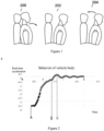
- Figure 1 illustrates changes in the status of a driver and a passenger during the braking process of a vehicle, wherein the vehicle uses a semi-active suspension of a Skyhook damping shock-absorbing control strategy and the vehicle comprises a CST system.
- the driver and passenger referred to herein refer to either or both of a driver and a passenger.
- the first stage 200 is the process where pitch of the vehicle where the driver and passenger are in starts
- the second stage 202 is an illustration of a driver and a passenger leaning forward due to inertia when the limit of vehicle pitch is reached and the vehicle shifts backwards
- the third stage 204 is an illustration of a driver and a passenger beginning to revert to the original state.
- Figure 2 is a plot of changes corresponding to acceleration output of the CST system during the braking of the vehicle shown in Figure 1 , wherein the horizontal axis indicates time and the vertical axis indicates vehicle acceleration.
- the intersection point B of the AB portion and the BC portion of the curve is the starting point for the compressed suspension to begin further compression and is also the point at which the vehicle enters the stationary state.
- the driver and passenger begin to lean forward, for example, as shown in the second stage 202 and lean backwards as shown in the third stage 204 of Figure 2 .
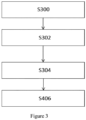
- FIG. 3 is a flow chart of a suspension control method for a vehicle using a CST (Comfort Stop) system according to some examples of the present application.
- a first group of signals and a second group of signals are obtained.
- the first group of signals and the second group of signals are obtained from related parts (for example, related sensor) or systems of the vehicle, wherein the first group of signals are signals related to the comfort braking control system CST and the second group of signals are signals related to driving expectations.
- signals related to the comfort braking control system CST refers to signals output by the CST controller, for example, comprising a status signal indicating the status of the CST, an actual acceleration signal indicating the actual acceleration of the vehicle, and a target acceleration signal indicating the target acceleration.
- the first group of signals comprises a status signal indicating the CST status, an actual acceleration signal indicating the actual acceleration of the vehicle, and a target acceleration signal indicating the target acceleration.
- the first group of signals may also use signals indicating the actual vehicle speed and the target vehicle speed, signals indicating the actual brake pressure and the target brake pressure, and the like.
- signals related to driving expectations refer to signals used to determine a driver's braking intent with respect to a vehicle. For example, signals indicating the driver's requested brake pressure size, signals indicating the speed at which the driver is stepping on the brake foot pedal, and signals indicating the road slope, all of which may be obtained from vehicle-related systems and/or parts (such as the brake system).
- step S302 whether the trigger condition is met is determined based on the first group of signals and the second group of signals.
- the trigger condition referred to herein refers to a condition used to determine an adjustment signal for adjusting the current suspension system, and is described further below in conjunction with Figure 4 .
- step S304 an adjustment signal for adjusting the vehicle suspension is determined based on related signals of the vehicle suspension system, in response to the trigger condition being met.
- related signals of the suspension system comprise a signal related to suspension stiffness, a signal related to suspension damping, and a signal related to suspension height.
- a signal related to suspension stiffness for example, is a current signal indicating suspension stiffness sent by a suspension stiffness controller; a signal related to suspension damping, for example, is a current signal indicating damping size sent by a damping controller; a signal related to current suspension height, for example, is a signal indicating the difference between the sprung height displacement of the suspension and unsprung height displacement of the suspension.
- the adjustment signal is a signal that indicates the target damping force. In other words, the adjustment target is the damping force of the suspension.
- the target damping force for adjusting the damping force of the suspension is determined based on a signal related to suspension stiffness, a signal related to suspension damping, and a signal related to suspension height.
- the adjustment signal may be determined according to a system of equations (1) in step 304.
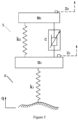
- a simplified equivalent chart of a semi-active suspension using a Skyhook damping shock-absorbing control strategy is illustrated in Figure 5 .
- a suspension 5 is simplified to comprise a sprung mass portion with a value of m 2 , a stiff spring portion with a stiffness value of k 2 , a damping portion with a damping value of c, and a unsprung mass portion with a value of m 1 .
- a tire 6 is simplified as a tire portion 6 having a stiffness value of k 1 .
- z 1 is an unsprung height value
- z 2 is a sprung height value
- z 2 -z 1 is a suspension compression value.
- c used as damping value in the system of equations (1), is selected among maximum damping value c max and conventional value c normal mode , as shown in equation (2).
- c max is selected for c when the target damping force is calculated according to the system of equations (1); but when the trigger condition is not met and when the target damping force is calculated according to the system of equations (1), conventional value c normal mode is selected for c.
- Damping force is used in the present application as a control target for adjusting the suspension, but control targets such as spring stiffness, suspension height, and the like may also be used for adjusting the suspension.
- the adjustment signal may be a signal indicating a target damping force in an example of the present application, but may also comprise or be a signal indicating target stiffness, a signal indicating target height, or the like.
- step S306 the suspension system controls the suspension based on the adjustment signal, i.e., the calculated adjustment signal is used by the suspension system (for example, the actuator of the suspension system) to adjust the suspension, so as to buffer the force generated by the compressed suspension returning to the original position thereof.
- the suspension system for example, the actuator of the suspension system
- the suspension is controlled by an actuator of the suspension system according to, for example, a target damping force F_Suspension determined according to the system of equation (1), so as to buffer the force generated when the compressed suspension returns to the original position thereof.
- a target damping force F_Suspension determined according to the system of equation (1), so as to buffer the force generated when the compressed suspension returns to the original position thereof.
- Figure 4 is a flow chart of a method for determining whether a trigger condition is met according to an example of the present application, i.e., a flow chart of the specific example of step S302 in Figure. 3 .
- step S400 whether a vehicle begins braking comfortably is determined based on the first group of signals and the second group of signals, i.e., whether the vehicle begins braking comfortably is determined based on a CST status signal output by the CST controller, an actual acceleration signal, a target acceleration signal, and a signal of the driver's intent to brake the vehicle.
- step S402 a first parameter is obtained from a first parameter table according to the actual acceleration signal output by the CST controller and a timing value for the timer is set according to the first parameter.
- step S404 a second parameter is obtained from a second parameter table according to a slope signal of the road the vehicle is driving on, and the timing value of the timer is modified according to the second parameter.
- step S406 whether timing by the timer is up is determined. If timing is up, the trigger condition is met, as shown in step S408.
- step S406 determines whether the timer counts down to zero. If the timer counts down to zero, the trigger condition is met. If the timing is not up, proceed to step S406.
- a first mapping table maps the relationship between acceleration and time from the start of the vehicle braking comfortably to the time when the vehicle is stationary.
- a second mapping table maps the relationship between the slope of the road and the duration of vehicle braking from the start of the vehicle braking comfortably to the time when the vehicle is stationary.
- the first and second mapping tables may be pre-set based on pre-testing and/or experience and may be continuously updated after the vehicle starts to be driven, as appropriate.
- the term "braking comfortably” refers to the braking process of a vehicle using the CST system.
- Point A shown in Figure 2 , is the starting point for the increase in vehicle acceleration, and is the point at which the timer starts timing in step S406 of Figure 4 .
- the method for controlling a suspension system determines whether a moving vehicle starts to brake comfortably based on the comfort braking control system and real-time data of related systems, and if it is determined that the vehicle has begun braking comfortably, i.e. related signals, such as target damping force of the vehicle suspension control system are combined in real-time to calculate the adjustment signal for controlling (may also be referred to as adjusting with respect to conventional suspension control) the work of the suspension system, the calculated adjustment signal is applied in real time to a suspension control system, for example, an actuator, such that the suspension is capable of working in a gentler manner during braking.
- related signals such as target damping force of the vehicle suspension control system
- FIG. 6 is a structural schematic diagram of a control system that may be applied to a suspension system of a vehicle according to some examples of the present application.
- the control system comprises a receiving module 60, a processing module 62, and an output module 64.
- the receiving module 60 is used to receive a first group of signals and a second group of signals.
- the processing module 62 is used to determine whether a trigger condition is met based on the first group of signals and the second group of signals, and, to determine an adjustment signal for adjusting the suspension system based on related signals of the suspension system, in response to the trigger condition being met.
- the output module 64 is used to output the adjustment signal.
- the receiving module 60 receives a first group of signals from the CST system, and more particularly, from a controller of the CST system, comprising a signal indicating the status of the CST, an actual acceleration signal indicating the actual acceleration of the vehicle, and a target acceleration signal indicating the target acceleration.
- the receiving module 60 receives a signal from a vehicle-related system and/or part that may be used to determine driving intent, i.e., a second group of signals, and the related system may be a vehicle brake system or a part thereof, and may also be a controller of a CST, and the like.
- a signal indicating the brake pressure size requested by the driver a signal indicating the speed at which the driver is stepping on the brake foot pedal, and a signal indicating the road slope obtained from the brake system of the vehicle.
- the processing module 62 may comprise a trigger unit 620 and a processing unit 622.
- the trigger unit 620 is configured to perform the process described above in conjunction with Figure 4 and to trigger the processing unit 622 when the trigger condition is met, such that the processing unit 622 determines the adjustment signal for adjusting the suspension system based on related signals of the suspension system.
- Related signals of the suspension system comprise a signal related to suspension stiffness, a signal related to suspension damping, and a signal related to suspension height, which are input to the processing unit 622 in order to determine the adjustment signal based on the parameter values that they each indicate.
- the adjustment signal herein is a signal indicating the target damping force.
- the processing unit 622 is configured to be capable of performing the above determination of the adjustment signal in conjunction with the step S304 of Figure. 3 . Hence, it will not be repeated herein.
- the system shown in Figure 6 may be implemented as hardware, software, or a combination of software and hardware.
- the modules when implemented in software, the modules may be implemented as software modules.
- the system as shown in Figure 6 may be applied to the vehicle as a standalone system and be communicatively connected to the suspension system and CST system to connect with other related systems and parts of the vehicle as desired.
- the system as shown in Figure 6 is implemented directly in an existing system of the vehicle, such as in software for implementation in a CST system controller.
- FIG. 7 is a structural schematic diagram of a suspension control system according to some examples of the present application.
- the suspension control system comprises a processor 74 connected to a comfort brake CST system controller 72 and a suspension control actuator 76.
- the processor 74 may obtain instructions from a memory 73.
- the memory 73 may be disposed outside of the processor 74 to exist as a standalone part; or the memory 73 may be memory already in the vehicle (such as a memory of the CST system or the suspension system); or the memory may be a storage part disposed within the processor 74.
- the memory is indicated in the figure by a dashed box 73 and is illustrated as being disposed outside of the processor 74, but may be implemented as one or a combination of the above-described dispositions.
- the processor 74 may obtain instructions from the memory 73 and execute them. When the processor 74 executes this instruction, the processor obtains a first group of signals related to the comfort braking control system from the CST system controller 72 and a second group of signals related to driving expectations from other related parts, such as the controller 70 of the vehicle brake system; the processor 74 determines whether the trigger condition is met based on these signals; and determines an adjustment signal for adjusting the vehicle suspension based on related signals of the vehicle suspension system from the suspension control system, in response to the trigger condition being met, and sends the determined adjustment signal to the suspension control actuator 76 for adjusting the suspension based on this.
- the processor 74 when executing the instructions, determines whether the trigger condition is met based on the following process implementations: determining whether a vehicle begins braking comfortably based on the first group of signals and the second group of signals; obtaining an actual acceleration signal from the CST controller 72, in response to the determination result that the vehicle has begun braking comfortably; obtaining a first parameter from a first parameter table; setting a timing value for a timer according to the first parameter; obtaining a road slope signal from. for example, a controller 70 of the vehicle brake system and obtaining a second parameter from a second parameter table; modifying the timing value according to the second parameter; determining that the trigger condition is met once the timer's timing is up.
- the suspension control system shown in Figure 7 which may perform the method for controlling a suspension system described in conjunction with Figures 3-5 .
- the processor 74 obtains a first group of signals from the comfort braking control system controller 72 and a related system and/or part of the vehicle obtains a second group of signals (step S300).
- the processor 74 determines whether the trigger condition is met based on the first group of signals and the second group of signals (step S302).
- the processor 74 performs the method for determining if a trigger condition is met as shown in Figure 4 to determine if the trigger condition is met.
- the processor 74 determines an adjustment signal for adjusting the suspension system based on related signals of the suspension system if the trigger condition is met (step S304).
- the processor 74 sends the determined adjustment signal to the suspension system actuator 76 so as to adjust the suspension system accordingly (step S306).
- the suspension system shown in Figure 7 wherein the processor 74 is a separate part, may also be implemented in the CST system, such as in the CST controller 72, or in the suspension control system, such as in the actuator 76 of the suspension control system.
- Whether a vehicle is about to brake comfortably may be determined by performing an example of the suspension control method of the present application, using an example of the system for controlling a suspension system of the present application, or using an example of the suspension control system of the present application example.
- This determination is based on existing signals of the vehicle's CST controller, such as a signal of CST status, vehicle acceleration signal, and the like, and takes into account a signal indicating driving intention that is collected by existing related systems and/or parts of the vehicle (for example, a signal related to the driver's stepping of the brake that is collected from the brake system).
- Changes in suspension damping force are modified in real time based on this such that the compression of the suspension becomes gentler in the recovery process from the braking to stopping of the vehicle, effectively preventing the occurrence of vehicle pitch phenomenon.
- Figure 8 is a plot of changes of acceleration output by the CST system during the braking of a vehicle, before and after an example of the suspension control method of the present application is performed, or an example of the system for controlling a suspension system is used, or an example of a suspension control system of the present application is used.
- the curve 80 shown in Figure 8 is the curve shown in Figure 2 , and is a plot of changes of acceleration output by the CST system during the braking of a vehicle before a scheme according to examples of the present application is adopted.
- the curve 82 is a plot of changes of acceleration output by the CST system during the braking of a vehicle after schemes according to examples of the present application are adopted, i.e., an example of the suspension control method of the present application is performed, or an example of the system for controlling a suspension system of the present application is used, or an example of a suspension control system of the present application is used, and is also a plot of desired and targeted changes of acceleration.
- the curve 82 is translated slightly to the right here, and in fact, point A of the curve 80 is supposed to be the same point as point A' of the curve 82, while the rest of the curve 82 is generally overlaid with the curve 80, except for the portions that differ from curve 80 after being adjusted to be gentler. As shown in Figure 8 , it can be seen that the BC segment of the curve 80 has been transformed into the B'C' segment of the curve 82, which is gentler.
- the present application also provides a controller for a suspension system comprising a processor and memory for storing instructions, the processor being configured to implement the control methods described above when executing the instructions.
- the controller may be incorporated into an existing suspension control system.
- the present application further provides a vehicle performing the method for controlling a suspension system as described above, or a vehicle using a system for controlling the suspension system as described above, or a vehicle using a suspension control system as described above.
- suspension mentioned in the above examples of the present application are semi-active suspensions of a Skyhook damping shock-absorbing control strategy, but the methods and systems of the examples of the present application are also applicable to other types of semi-active suspensions, such as suspensions using continuous damping control (CDC) systems and suspensions using magnetorheological dampers (MRD).
- CDC continuous damping control
- MRD magnetorheological dampers
Landscapes
- Engineering & Computer Science (AREA)
- Mechanical Engineering (AREA)
- Transportation (AREA)
- Automation & Control Theory (AREA)
- General Engineering & Computer Science (AREA)
- Vehicle Body Suspensions (AREA)
- Regulating Braking Force (AREA)
Applications Claiming Priority (1)
| Application Number | Priority Date | Filing Date | Title |
|---|---|---|---|
| CN202310175221.1A CN118372598A (zh) | 2023-02-27 | 2023-02-27 | 用于悬架系统的控制方法、控制系统及悬架控制系统 |
Publications (2)
| Publication Number | Publication Date |
|---|---|
| EP4438352A2 true EP4438352A2 (de) | 2024-10-02 |
| EP4438352A3 EP4438352A3 (de) | 2024-10-16 |
Family
ID=88965197
Family Applications (1)
| Application Number | Title | Priority Date | Filing Date |
|---|---|---|---|
| EP23211799.4A Pending EP4438352A3 (de) | 2023-02-27 | 2023-11-23 | Verfahren zur steuerung eines aufhängungssystems, steuerungssystem und aufhängungssteuerungssystem |
Country Status (7)
| Country | Link |
|---|---|
| US (1) | US20240286450A1 (de) |
| EP (1) | EP4438352A3 (de) |
| JP (1) | JP2024128997A (de) |
| KR (1) | KR20240133628A (de) |
| CN (1) | CN118372598A (de) |
| AU (1) | AU2024201260A1 (de) |
| TW (1) | TWI897252B (de) |
Family Cites Families (13)
| Publication number | Priority date | Publication date | Assignee | Title |
|---|---|---|---|---|
| US6701235B2 (en) * | 2000-08-31 | 2004-03-02 | Tokico Ltd. | Suspension control system |
| JP2005247068A (ja) * | 2004-03-02 | 2005-09-15 | Yokohama Rubber Co Ltd:The | 路面状態検出システム及びアクティブ・サスペンション・システム及びアンチロック・ブレーキ・システム並びにそのセンサユニット |
| JP5158333B2 (ja) * | 2007-09-28 | 2013-03-06 | 日立オートモティブシステムズ株式会社 | サスペンション制御装置 |
| JP6236884B2 (ja) * | 2013-06-04 | 2017-11-29 | アイシン精機株式会社 | 車両制御装置 |
| CN103448792A (zh) * | 2013-08-30 | 2013-12-18 | 郑州宇通客车股份有限公司 | 混合动力车的双驱动助力转向系统和控制方法 |
| US9428242B2 (en) * | 2014-02-24 | 2016-08-30 | Harley-Davidson Motor Company Group, LLC | Variable ride height systems and methods |
| JP6357127B2 (ja) * | 2015-03-19 | 2018-07-11 | 本田技研工業株式会社 | 車両のサスペンション制御装置 |
| GB2552028B (en) * | 2016-07-08 | 2020-07-08 | Jaguar Land Rover Ltd | Off-Road Route Rating System |
| JP2018070080A (ja) * | 2016-11-04 | 2018-05-10 | ローベルト ボッシュ ゲゼルシャフト ミット ベシュレンクテル ハフツング | 車両のブレーキシステムが車輪に生じさせるブレーキ力を制御する制御装置、及び、制御方法 |
| CN110525401A (zh) * | 2019-08-15 | 2019-12-03 | 芜湖伯特利汽车安全系统股份有限公司 | 一种提升车辆制动舒适性的方法 |
| MX2022015902A (es) * | 2020-07-17 | 2023-01-24 | Polaris Inc | Suspensiones ajustables y operacion de vehiculo para vehiculos recreativos todoterreno. |
| CN116568572A (zh) * | 2021-12-07 | 2023-08-08 | 华为技术有限公司 | 制动控制方法及相关装置 |
| CN117284309A (zh) * | 2022-06-17 | 2023-12-26 | 罗伯特·博世有限公司 | 用于车辆的舒适制动控制系统和控制方法 |
-
2023
- 2023-02-27 CN CN202310175221.1A patent/CN118372598A/zh active Pending
- 2023-11-23 EP EP23211799.4A patent/EP4438352A3/de active Pending
-
2024
- 2024-01-21 US US18/418,299 patent/US20240286450A1/en active Pending
- 2024-02-21 JP JP2024024334A patent/JP2024128997A/ja active Pending
- 2024-02-22 TW TW113106367A patent/TWI897252B/zh active
- 2024-02-26 KR KR1020240027194A patent/KR20240133628A/ko active Pending
- 2024-02-26 AU AU2024201260A patent/AU2024201260A1/en active Pending
Also Published As
| Publication number | Publication date |
|---|---|
| CN118372598A (zh) | 2024-07-23 |
| JP2024128997A (ja) | 2024-09-26 |
| KR20240133628A (ko) | 2024-09-04 |
| TW202446620A (zh) | 2024-12-01 |
| EP4438352A3 (de) | 2024-10-16 |
| US20240286450A1 (en) | 2024-08-29 |
| AU2024201260A1 (en) | 2024-09-12 |
| TWI897252B (zh) | 2025-09-11 |
Similar Documents
| Publication | Publication Date | Title |
|---|---|---|
| EP2808189B1 (de) | Fahrzeugsteuerungssystem | |
| US7406371B2 (en) | Suspension control system | |
| EP2808191B1 (de) | Fahrzeugsteuerungssystem und fahrzeugsteuerungsverfahren | |
| CN104024008B (zh) | 车辆的控制装置 | |
| CN102300729B (zh) | 用于对机动车进行行车平衡调节的方法及用于实施的装置 | |
| US9452653B2 (en) | Vehicle controlling apparatus and method | |
| EP2808214B1 (de) | Fahrzeugsteuerungssystem und fahrzeugsteuerungsverfahren | |
| EP3950391B1 (de) | Verfahren zur steuerung einer radaufhängung | |
| JP6292161B2 (ja) | 制動力制御装置 | |
| US8874314B2 (en) | Vehicle damping control apparatus | |
| CN102325662B (zh) | 衰减力控制装置 | |
| EP2808210B1 (de) | Fahrzeugsteuerungssystem und fahrzeugsteuerungsverfahren | |
| US9150074B2 (en) | Control apparatus for vehicle | |
| JP6233609B2 (ja) | 車両の駆動力制御装置 | |
| EP2808190A1 (de) | Fahrzeugsteuerungssystem und fahrzeugsteuerungsverfahren | |
| EP4438352A2 (de) | Verfahren zur steuerung eines aufhängungssystems, steuerungssystem und aufhängungssteuerungssystem | |
| CN118617921A (zh) | 刚度与阻尼的协同控制方法、悬架系统、车辆及存储介质 | |
| JP2013241075A (ja) | サスペンション制御装置 | |
| JP5224058B2 (ja) | サスペンション制御装置 | |
| CN118019653A (zh) | 车辆控制装置以及车辆控制系统 | |
| JP2026048289A (ja) | 車両の制御システム及び制御方法 | |
| KR102775075B1 (ko) | 차량용 자세 제어방법 및 장치 | |
| JP2026048288A (ja) | 車両の制御システム及び制御方法 | |
| GB2643401A (en) | A control system for a damper of a suspension system | |
| JP2025089056A (ja) | 車両制御装置 |
Legal Events
| Date | Code | Title | Description |
|---|---|---|---|
| PUAI | Public reference made under article 153(3) epc to a published international application that has entered the european phase |
Free format text: ORIGINAL CODE: 0009012 |
|
| STAA | Information on the status of an ep patent application or granted ep patent |
Free format text: STATUS: THE APPLICATION HAS BEEN PUBLISHED |
|
| PUAL | Search report despatched |
Free format text: ORIGINAL CODE: 0009013 |
|
| AK | Designated contracting states |
Kind code of ref document: A2 Designated state(s): AL AT BE BG CH CY CZ DE DK EE ES FI FR GB GR HR HU IE IS IT LI LT LU LV MC ME MK MT NL NO PL PT RO RS SE SI SK SM TR |
|
| AK | Designated contracting states |
Kind code of ref document: A3 Designated state(s): AL AT BE BG CH CY CZ DE DK EE ES FI FR GB GR HR HU IE IS IT LI LT LU LV MC ME MK MT NL NO PL PT RO RS SE SI SK SM TR |
|
| RIC1 | Information provided on ipc code assigned before grant |
Ipc: B60W 30/18 20120101ALI20240912BHEP Ipc: B60T 8/32 20060101ALI20240912BHEP Ipc: B60G 17/016 20060101AFI20240912BHEP |
|
| STAA | Information on the status of an ep patent application or granted ep patent |
Free format text: STATUS: REQUEST FOR EXAMINATION WAS MADE |
|
| 17P | Request for examination filed |
Effective date: 20250416 |
|
| STAA | Information on the status of an ep patent application or granted ep patent |
Free format text: STATUS: EXAMINATION IS IN PROGRESS |
|
| 17Q | First examination report despatched |
Effective date: 20260120 |