EP4438269A1 - Automatische bauteilentfernung - Google Patents
Automatische bauteilentfernung Download PDFInfo
- Publication number
- EP4438269A1 EP4438269A1 EP23165467.4A EP23165467A EP4438269A1 EP 4438269 A1 EP4438269 A1 EP 4438269A1 EP 23165467 A EP23165467 A EP 23165467A EP 4438269 A1 EP4438269 A1 EP 4438269A1
- Authority
- EP
- European Patent Office
- Prior art keywords
- component
- construction platform
- printing device
- platform
- printing
- Prior art date
- Legal status (The legal status is an assumption and is not a legal conclusion. Google has not performed a legal analysis and makes no representation as to the accuracy of the status listed.)
- Pending
Links
Images


Classifications
-
- B—PERFORMING OPERATIONS; TRANSPORTING
- B29—WORKING OF PLASTICS; WORKING OF SUBSTANCES IN A PLASTIC STATE IN GENERAL
- B29C—SHAPING OR JOINING OF PLASTICS; SHAPING OF MATERIAL IN A PLASTIC STATE, NOT OTHERWISE PROVIDED FOR; AFTER-TREATMENT OF THE SHAPED PRODUCTS, e.g. REPAIRING
- B29C64/00—Additive manufacturing, i.e. manufacturing of three-dimensional [3D] objects by additive deposition, additive agglomeration or additive layering, e.g. by 3D printing, stereolithography or selective laser sintering
- B29C64/10—Processes of additive manufacturing
- B29C64/106—Processes of additive manufacturing using only liquids or viscous materials, e.g. depositing a continuous bead of viscous material
- B29C64/112—Processes of additive manufacturing using only liquids or viscous materials, e.g. depositing a continuous bead of viscous material using individual droplets, e.g. from jetting heads
-
- B—PERFORMING OPERATIONS; TRANSPORTING
- B29—WORKING OF PLASTICS; WORKING OF SUBSTANCES IN A PLASTIC STATE IN GENERAL
- B29C—SHAPING OR JOINING OF PLASTICS; SHAPING OF MATERIAL IN A PLASTIC STATE, NOT OTHERWISE PROVIDED FOR; AFTER-TREATMENT OF THE SHAPED PRODUCTS, e.g. REPAIRING
- B29C64/00—Additive manufacturing, i.e. manufacturing of three-dimensional [3D] objects by additive deposition, additive agglomeration or additive layering, e.g. by 3D printing, stereolithography or selective laser sintering
- B29C64/30—Auxiliary operations or equipment
- B29C64/379—Handling of additively manufactured objects, e.g. using robots
-
- B—PERFORMING OPERATIONS; TRANSPORTING
- B29—WORKING OF PLASTICS; WORKING OF SUBSTANCES IN A PLASTIC STATE IN GENERAL
- B29C—SHAPING OR JOINING OF PLASTICS; SHAPING OF MATERIAL IN A PLASTIC STATE, NOT OTHERWISE PROVIDED FOR; AFTER-TREATMENT OF THE SHAPED PRODUCTS, e.g. REPAIRING
- B29C64/00—Additive manufacturing, i.e. manufacturing of three-dimensional [3D] objects by additive deposition, additive agglomeration or additive layering, e.g. by 3D printing, stereolithography or selective laser sintering
- B29C64/20—Apparatus for additive manufacturing; Details thereof or accessories therefor
- B29C64/245—Platforms or substrates
-
- B—PERFORMING OPERATIONS; TRANSPORTING
- B29—WORKING OF PLASTICS; WORKING OF SUBSTANCES IN A PLASTIC STATE IN GENERAL
- B29C—SHAPING OR JOINING OF PLASTICS; SHAPING OF MATERIAL IN A PLASTIC STATE, NOT OTHERWISE PROVIDED FOR; AFTER-TREATMENT OF THE SHAPED PRODUCTS, e.g. REPAIRING
- B29C64/00—Additive manufacturing, i.e. manufacturing of three-dimensional [3D] objects by additive deposition, additive agglomeration or additive layering, e.g. by 3D printing, stereolithography or selective laser sintering
- B29C64/20—Apparatus for additive manufacturing; Details thereof or accessories therefor
- B29C64/295—Heating elements
-
- B—PERFORMING OPERATIONS; TRANSPORTING
- B29—WORKING OF PLASTICS; WORKING OF SUBSTANCES IN A PLASTIC STATE IN GENERAL
- B29C—SHAPING OR JOINING OF PLASTICS; SHAPING OF MATERIAL IN A PLASTIC STATE, NOT OTHERWISE PROVIDED FOR; AFTER-TREATMENT OF THE SHAPED PRODUCTS, e.g. REPAIRING
- B29C64/00—Additive manufacturing, i.e. manufacturing of three-dimensional [3D] objects by additive deposition, additive agglomeration or additive layering, e.g. by 3D printing, stereolithography or selective laser sintering
- B29C64/30—Auxiliary operations or equipment
- B29C64/35—Cleaning
-
- B—PERFORMING OPERATIONS; TRANSPORTING
- B29—WORKING OF PLASTICS; WORKING OF SUBSTANCES IN A PLASTIC STATE IN GENERAL
- B29C—SHAPING OR JOINING OF PLASTICS; SHAPING OF MATERIAL IN A PLASTIC STATE, NOT OTHERWISE PROVIDED FOR; AFTER-TREATMENT OF THE SHAPED PRODUCTS, e.g. REPAIRING
- B29C64/00—Additive manufacturing, i.e. manufacturing of three-dimensional [3D] objects by additive deposition, additive agglomeration or additive layering, e.g. by 3D printing, stereolithography or selective laser sintering
- B29C64/40—Structures for supporting 3D objects during manufacture and intended to be sacrificed after completion thereof
-
- B—PERFORMING OPERATIONS; TRANSPORTING
- B33—ADDITIVE MANUFACTURING TECHNOLOGY
- B33Y—ADDITIVE MANUFACTURING, i.e. MANUFACTURING OF THREE-DIMENSIONAL [3D] OBJECTS BY ADDITIVE DEPOSITION, ADDITIVE AGGLOMERATION OR ADDITIVE LAYERING, e.g. BY 3D PRINTING, STEREOLITHOGRAPHY OR SELECTIVE LASER SINTERING
- B33Y10/00—Processes of additive manufacturing
-
- B—PERFORMING OPERATIONS; TRANSPORTING
- B33—ADDITIVE MANUFACTURING TECHNOLOGY
- B33Y—ADDITIVE MANUFACTURING, i.e. MANUFACTURING OF THREE-DIMENSIONAL [3D] OBJECTS BY ADDITIVE DEPOSITION, ADDITIVE AGGLOMERATION OR ADDITIVE LAYERING, e.g. BY 3D PRINTING, STEREOLITHOGRAPHY OR SELECTIVE LASER SINTERING
- B33Y30/00—Apparatus for additive manufacturing; Details thereof or accessories therefor
-
- B—PERFORMING OPERATIONS; TRANSPORTING
- B33—ADDITIVE MANUFACTURING TECHNOLOGY
- B33Y—ADDITIVE MANUFACTURING, i.e. MANUFACTURING OF THREE-DIMENSIONAL [3D] OBJECTS BY ADDITIVE DEPOSITION, ADDITIVE AGGLOMERATION OR ADDITIVE LAYERING, e.g. BY 3D PRINTING, STEREOLITHOGRAPHY OR SELECTIVE LASER SINTERING
- B33Y40/00—Auxiliary operations or equipment, e.g. for material handling
Definitions
- the present invention relates to a method for printing a three-dimensional component, a construction platform for a printing device and a printing device for printing a three-dimensional component.
- the printed components are removed mechanically from the build platform using a spatula or other means; this is done while the build platform remains in the printer or after the build platform has been removed from the printer.
- the build platform is then cleaned and, if necessary, reinserted into the printer. This requires a large number of manual steps and results in an interruption of the workflow.
- the technical problem is solved by a method for printing a three-dimensional component, comprising the steps of heating a construction platform to melt a material component in order to form a sliding film between the component and the construction platform; and Removing the component from the build platform.
- This process enables continuous printing of components without manual intervention.
- the material component is integrated into a support structure of the component. This achieves the technical advantage, for example, that a sliding film can be easily created under the component when the construction platform is heated.
- the material component is applied to the construction platform. This achieves the technical advantage, for example, that non-meltable support structure material can also be used.
- the meltable material component is arranged over a large area across the entire construction platform or selectively underneath the component. This also achieves the technical advantage that the component can be built up at different locations on the construction platform.
- the meltable material component is selectively applied using an integrated inkjet module.
- an integrated inkjet module can be used for application.
- a stereolithography module, a fused deposition modeling module (FDM) or any other module suitable for applying the meltable material component can also be used.
- the component is pushed off the construction platform on the sliding film. This achieves the technical advantage, for example, that the component can be efficiently removed from the construction platform.
- the meltable material component comprises polyethylene glycol, polyvinyl acetate, paraffin or wax. This achieves the technical advantage that the material can be easily melted.
- the fusible material component is removed from the construction platform after the component has been removed. This achieves the technical advantage, for example, that the construction platform can be used for another construction job. This also has the technical advantage that a controlled application of the fusible material component can be ensured or the construction platform can also be used for another job without the fusible material component.
- the construction platform is cooled after the component has been removed. This achieves the technical advantage, for example, that the construction platform is available again more quickly for another construction job.
- the meltable material component is removed from the component. This achieves the technical advantage that the component can be further processed.
- a construction platform for a printing device which comprises a heating device for melting a meltable material component in order to form a sliding film between the component and the construction platform.
- the construction platform achieves the same technical advantages as the method according to the first aspect.
- the technical problem is solved by a printing device for printing a three-dimensional component, with a construction platform according to the first aspect.
- the printing device achieves the same technical advantages as the method according to the first aspect.
- the printing device comprises an application device for applying the meltable material component to the construction platform. This achieves the technical advantage, for example, that the construction platform can be automatically provided with the meltable material component.
- the printing device comprises a sliding device for sliding the component from the construction platform.
- a sliding device for sliding the component from the construction platform.
- the printing device comprises an opening in the housing for ejecting the component. After ejection, the component can be collected in a collecting container or a collecting device. This achieves the technical advantage, for example, that no manual removal of the component including the support structure from the printing device is necessary and the printing process is thus not disrupted.
- the printing device comprises a removal device for removing the sliding film from the construction platform. This achieves the technical advantage, for example, that the construction platform is ready for a new print job.
- the removal device is formed by a blade. This achieves the technical advantage, for example, that the meltable material component can be removed evenly or completely and the construction platform is ready for the next construction job.
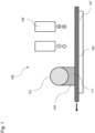
- Fig. 1 shows a schematic view of a component 101 with a support structure 103 made of a meltable material component 117.
- the component 101 is constructed on the construction platform 105 from a material that is applied using an inkjet process.
- a support structure 103 made of a meltable material component 117 is used for the component 101, which is also applied using the inkjet process using a printing nozzle 129.
- the component 101 can also be constructed using another process.
- the construction platform 105 can be heated for a short time so that the support material 103 melts and a sliding film 125 is formed between component 101 and construction platform 105.
- the printing device 100 comprises a heating device 107 that heats the construction platform 105.
- the heating device 107 is, for example, an electrical heating device that is controlled by the printing device 100.
- the component 101 together with the support structure 103 is then pushed by means of a squeegee from the construction platform 105 through a hatch from the printing device 100 into a collecting vessel.
- the heating creates a sliding film 125 between the construction platform 105 and the component 101, the force required to push the component 101 together with the support structure 103 off the construction platform is minimal and the component 101 is not mechanically stressed.
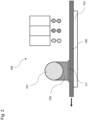
- Fig. 2 shows a schematic view of a component 101 on a meltable material component 117 applied as a layer.
- the material component 117 is applied as a layer on the construction platform 105 using the inkjet method.
- the support structure 103 made of support material is built on this layer and the component 101 made of a construction material is built on the support structure 103 using the inkjet method.
- the material component 117 can also be applied thinly to the construction platform 105 as a separate, meltable material. The application can be carried out over a large area over the entire construction platform 105 or selectively below the component 101.
- Fig. 3 shows a further schematic view of a component 101 on a layered, fusible Material component 117.
- the material component 117 is applied over a large area to the construction platform 105 using a slot dispenser 121 as an application device 115.
- the support structure 103 is constructed on the material component 117 using the inkjet method and the component 101 is constructed from a construction material on the support structure 103 using the inkjet method.
- Fig. 4 shows another schematic view of a component 101 on a meltable material component 117 applied as a layer.
- the material component 117 is applied over a large area on the construction platform 105.
- the heated construction platform 105 is guided underneath a wax plate that is held in a shaft 127.
- the wax plate melts onto the front or base of the construction platform 105.
- the component 101 is then produced using the component material and support material on the thin wax film, which is then melted again for automatic removal of the component 101.
- Fig. 5 shows a printing device 100 with a resealable opening with a rotatable flap 123.
- the component 101 can be moved out of the printing device 100 via the flap 123.
- the bottom layer of the support structure 103 is melted on the temporarily heated construction platform 105 so that a sliding film 125 is created from the meltable material component 117.
- Fig. 6 shows the material component 117 melted to the sliding film 125 through the temporarily heated construction platform 105.
- a doctor blade 127 as a pushing device 109 pushes the component 101 together with the support structure 103 from the construction platform 105.
- the pushing device 109 pushes the component 101 in a horizontal direction on the sliding film 125 made of the heated material component 117 from the construction platform 105.
- the squeegee 127 has, for example, a blade in contact with the construction platform 105, which is designed as a metal blade or a silicone blade.
- a collecting container or a conveying mechanism can be arranged outside the printing device 100 in order to receive the component 101 or to convey it to another location where it is, for example, freed of support material, cleaned and reworked.
- the printing device 100 comprises a removal device 111, which is formed by an elongated blade 113.
- the blade 113 is in contact with the construction platform 105.
- the construction platform 105 and the blade 113 are moved against each other in such a way that the sliding film 125 is stripped off. After that, the process can continue with a new application of the meltable material component and/or the new construction of another component 101.
- the construction platform 105 can be cooled by means of a cooling device 119, such as a water circuit or a Peltier element. This allows the construction platform 105 to be quickly used again for the next print job without a sliding film 125 initially forming.
- a cooling device 119 such as a water circuit or a Peltier element.
- Fig. 8 shows a block diagram of a method for printing the three-dimensional component.
- a meltable material component 117 is applied to the construction platform 105.
- the material component 117 can be applied as a layer on the construction platform 105 or integrated into a support structure 103 of the component 105.
- the construction platform 105 is heated in step S101 to melt the material component 117. This creates a sliding film 125 between the component 101 and the construction platform 105.
- step S102 the component 101 is pushed off the construction platform 105.
- the method allows fully printed components 101 to be automatically removed from the construction platform 105 after the print job has been completed. This makes the construction platform 105 ready for the following component 101. This enables continuous printing of components 101 without manual intervention.
- All process steps can be implemented by devices that are suitable for carrying out the respective process step. All functions that objective features can be a procedural step of a procedure.
Landscapes
- Engineering & Computer Science (AREA)
- Chemical & Material Sciences (AREA)
- Materials Engineering (AREA)
- Manufacturing & Machinery (AREA)
- Physics & Mathematics (AREA)
- Mechanical Engineering (AREA)
- Optics & Photonics (AREA)
- Robotics (AREA)
- Ink Jet (AREA)
Abstract
Die vorliegende Erfindung betrifft ein Verfahren zum Drucken eines dreidimensionalen Bauteils (101), mit den Schritten eines Erwärmens (S101) einer Bauplattform zum Schmelzen einer Materialkomponente, um einen Gleitfilm zwischen dem Bauteil und der Bauplattform zu bilden; und Entfernen (S102) des Bauteiles (101) von der Bauplattform.
Description
- Die vorliegende Erfindung betrifft ein Verfahren zum Drucken eines dreidimensionalen Bauteils, eine Bauplattform für eine Druckvorrichtung und eine Druckvorrichtung zum Drucken eines dreidimensionalen Bauteils.
- Bei den derzeit bekannten Inkjet-3D-Druckern werden die gedruckten Bauteile mit einem Spatel oder anderweitig mechanisch von der Bauplattform entfernt; dies erfolgt bei Verbleib der Bauplattform im Drucker oder nach Entnahme der Bauplattform aus dem Drucker. Danach wird die Bauplattform gereinigt, ggf. wieder im Drucker eingesetzt. Dies erfordert eine Vielzahl von manuellen Arbeitsschritten und bedingt eine Unterbrechung des Arbeitsablaufes.
- Es ist die technische Aufgabe der vorlinden Erfindung, die fertig gedruckten Bauteile nach Beendigung des Druckens automatisch von der Bauplattform zu entfernen und so die Bauplattform für den folgenden Druckprozess bereit zu machen.
- Diese Aufgabe wird durch Gegenstände nach den unabhängigen Ansprüchen gelöst. Technisch vorteilhafte Ausführungsformen sind Gegenstand der abhängigen Ansprüche, der Beschreibung und der Zeichnungen.
- Gemäß einem ersten Aspekt wird die technische Aufgabe durch ein Verfahren zum Drucken eines dreidimensionalen Bauteils gelöst, mit den Schritten eines Erwärmens einer Bauplattform zum Schmelzen einer Materialkomponente, um einen Gleitfilm zwischen dem Bauteil und der Bauplattform zu bilden; und Entfernen des Bauteiles von der Bauplattform. Durch das Verfahren wird ein kontinuierliches Drucken von Bauteilen ohne manuellen Eingriff ermöglicht.
- In einer technisch vorteilhaften Ausführungsform des Verfahrens ist die Materialkomponente in einer Stützstruktur des Bauteiles intergiert. Dadurch wird beispielsweise der technische Vorteil erreicht, dass auf einfache Weise unter dem Bauteil ein Gleitfilm beim Erwärmen der Bauplattform erzeugt werden kann.
- In einer weiteren technisch vorteilhaften Ausführungsform des Verfahrens ist die Materialkomponente auf die Bauplattform aufgetragen. Dadurch wird beispielsweise der technische Vorteil erreicht, dass auch nicht schmelzbares Stützstrukturmaterial verwendet werden kann.
- In einer weiteren technisch vorteilhaften Ausführungsform des Verfahrens wird die schmelzbare Materialkomponente großflächig über die gesamte Bauplattform oder selektiv unterhalb des Bauteiles angeordnet. Dadurch wird beispielsweise ebenfalls der technische Vorteil erreicht, dass das Bauteil an unterschiedlichen Stellen auf der Bauplattform aufgebaut werden kann.
- In einer weiteren technisch vorteilhaften Ausführungsform des Verfahrens erfolgt der selektive Auftrag der schmelzbaren Materialkomponente durch ein integriertes Inkjet-Modul. Dadurch wird beispielsweise der technische Vorteil erreicht, dass das bereits vorhandene Inkjet-Module zum Auftrag genutzt werden können. Im Allgemeinen kann aber auch ein Stereolithografie-Modul, ein Schmelzschichtung-Modul (FDM - Fused Deposition Modeling) oder jedes andere Modul verwendet werden, das zum Auftragen der schmelzbaren Materialkomponente geeignet ist.
- In einer weiteren technisch vorteilhaften Ausführungsform des Verfahrens wird das Bauteil auf dem Gleitfilm von der Bauplattform geschoben. Dadurch wird beispielsweise der technische Vorteil erreicht, dass das Bauteil effizient von der Bauplattform entfernt werden kann.
- In einer weiteren technisch vorteilhaften Ausführungsform des Verfahrens umfasst die schmelzbare Materialkomponente Polyethylenglykol, Polyvinylacetat, Paraffin oder Wachs. Dadurch wird beispielsweise der technische Vorteil erreicht, dass sich das Material leicht anschmelzen lässt.
- In einer weiteren technisch vorteilhaften Ausführungsform des Verfahrens wird die schmelzbare Materialkomponente nach dem Entfernen des Bauteiles von der Bauplattform entfernt. Dadurch wird beispielsweise der technische Vorteil erreicht, dass die Bauplattform für einen weiteren Bauauftrag verwendet werden kann. Dies hat zusätzlich den technischen Vorteil, dass ein kontrollierter Auftrag der schmelzbaren Materialkomponente gewährleistet werden kann oder die Bauplattform auch ohne die schmelzbare Materialkomponente für einen weiteren Auftrag verwendet werden.
- In einer weiteren technisch vorteilhaften Ausführungsform des Verfahrens wird die Bauplattform nach dem Entfernen des Bauteils gekühlt. Dadurch wird beispielsweise der technische Vorteil erreicht, dass die Bauplattform schneller wieder für einen weiteren Bauauftrag zu Verfügung steht.
- In einer weiteren technisch vorteilhaften Ausführungsform des Verfahrens wird die schmelzbare Materialkomponente von dem Bauteil entfernt. Dadurch wird beispielsweise der technische Vorteil erreicht, dass das Bauteil weiterverarbeitet werden kann.
- Gemäß einem zweiten Aspekt wird die technische Aufgabe durch eine Bauplattform für eine Druckvorrichtung gelöst, die eine Heizeinrichtung zum Schmelzen einer schmelzbaren Materialkomponente umfasst, um einen Gleitfilm zwischen dem Bauteil und der Bauplattform zu bilden. Durch die Bauplattform werden die gleichen technischen Vorteile wie durch das Verfahren nach dem ersten Aspekt erreicht.
- Gemäß einem dritten Aspekt wird die technische Aufgabe durch eine Druckvorrichtung zum Drucken eines dreidimensionalen Bauteils gelöst, mit einer Bauplattform nach dem ersten Aspekt. Durch die Druckvorrichtung werden die gleichen technischen Vorteile wie durch das Verfahren nach dem ersten Aspekt erreicht.
- In einer technisch vorteilhaften Ausführungsform der Druckvorrichtung umfasst die Druckvorrichtung eine Auftragungsvorrichtung zum Auftragen der schmelzbaren Materialkomponente auf die Bauplattform. Dadurch wird beispielsweise der technische Vorteil erreicht, dass die Bauplattform automatisch mit der schmelzbaren Materialkomponente versehen werden kann.
- In einer weiteren technisch vorteilhaften Ausführungsform der Druckvorrichtung umfasst die Druckvorrichtung eine Schiebevorrichtung zum Schieben des Bauteiles von der Bauplattform. Dadurch wird beispielsweise der technische Vorteil erreicht, dass das Bauteil schnell entfernt werden kann. Zusätzlich kann vorgesehen sein, dass zwischen den Bauteil und der Bauplattform ein Stützstruktur vorgesehen ist, die auch wie im oben erwähnten technischen Vorteil zum Tragen kommen kann und somit das Bauteil mitsamt der Stützstruktur automatisch entfernt werden kann.
- In einer weiteren technisch vorteilhaften Ausführungsform der Druckvorrichtung umfasst die Druckvorrichtung eine Öffnung im Gehäuse zum Auswurf des Bauteils. Das Bauteil kann nach dem Auswurf in einem Auffangbehälter oder einer Auffangvorrichtung aufgenommen werden. Dadurch wird beispielsweise der technische Vorteil erreicht, dass keine manuelle Entnahme des Bauteils mitsamt Stützstruktur aus der Druckvorrichtung erforderlich ist und so der Druckvorgang nicht gestört wird.
- In einer weiteren technisch vorteilhaften Ausführungsform der Druckvorrichtung umfasst die Druckvorrichtung eine Entfernungsvorrichtung zum Entfernen des Gleitfilms von der Bauplattform. Dadurch wird beispielsweise der technische Vorteil erreicht, dass die Bauplattform für einen neuen Druckauftrag bereitsteht.
- In einer weiteren technisch vorteilhaften Ausführungsform der Druckvorrichtung ist die Entfernungsvorrichtung durch eine Klinge gebildet. Dadurch wird beispielsweise der technische Vorteil erreicht, dass die schmelzbare Materialkomponente gleichmäßig oder restlos entfernt werden kann und die Bauplattform für den nächsten Bauauftrag bereit ist.
- Ausführungsbeispiele der Erfindung sind in den Zeichnungen dargestellt und werden im Folgenden näher beschrieben.
- Es zeigen:
- Fig. 1
- eine schematische Ansicht eines Bauteils mit einer Stützstruktur aus einem schmelzbaren Material;
- Fig. 2
- eine schematische Ansicht eines Bauteils auf einem als Schicht aufgetragenen, schmelzbaren Material;
- Fig. 3
- eine weitere schematische Ansicht eines Bauteils auf einem als Schicht aufgetragenen, schmelzbaren Material;
- Fig. 4
- eine weitere schematische Ansicht eines Bauteils auf einem als Schicht aufgetragenen, schmelzbaren Material;
- Fig. 5
- eine schematische Ansicht einer Druckvorrichtung mit einer wiederverschließbaren Öffnung;
- Fig. 6
- eine schematische Ansicht einer zum Gleitfilm angeschmolzene Materialkomponente;
- Fig. 7
- eine schematische Ansicht einer Druckvorrichtung mit einer geöffneten, wiederverschließbaren Öffnung; und
- Fig. 8
- ein Blockdiagramm eines Verfahrens zum Drucken eines dreidimensionalen Bauteils.
-
Fig. 1 zeigt eine schematische Ansicht eines Bauteils 101 mit einer Stützstruktur 103 aus einer schmelzbaren Materialkomponente 117. Das Bauteil 101 wird auf der Bauplattform 105 aus einem Material aufgebaut, das mittels eines Inkjet-Verfahrens aufgetragen wird. Für das Bauteil 101 wird eine Stützstruktur 103 aus einer schmelzbaren Materialkomponente 117 verwendet, das ebenfalls mittels des Inkjet-Verfahrens mittels einer Druckdüse 129 aufgetragen wird. Im Allgemeinen kann das Bauteil 101 aber auch mittels eines anderen Verfahrens aufgebaut werden. - Bei der Auswahl eines Stützmaterials mit einer schmelzbaren Materialkomponente 117 nach dem Drucken des Bauteils 101 kann die Bauplattform 105 kurzzeitig aufgeheizt werden, damit das Stützmaterial 103 anschmilzt und so ein Gleitfilm 125 zwischen Bauteil 101 und Bauplattform 105 entsteht. Zu diesem Zweck umfasst die Druckvorrichtung 100 eine Heizeinrichtung 107, die die Bauplattform 105 erwärmt. Die Heizeinrichtung 107 ist beispielsweise eine elektrische Heizeinrichtung, die durch die Druckvorrichtung 100 gesteuert wird.
- Das Bauteil 101 mitsamt der Stützstruktur 103 wird dann, sobald das Stützmaterial auf der Bauplattformoberfläche angeschmolzen ist, mittels einer Rakel von der Bauplattform 105 durch eine Luke aus der Druckvorrichtung 100 in ein Auffanggefäß geschoben.
- Dadurch dass durch die Erwärmung ein Gleitfilm 125 zwischen der Bauplattform 105 und dem Bauteil 101 entsteht, ist der Kraftaufwand zum Herunterschieben des Bauteils 101 mitsamt Stützstruktur 103 von der Bauplattform minimal und das Bauteil 101 wird mechanisch nicht belastet.
-
Fig. 2 zeigt eine schematische Ansicht eines Bauteils 101 auf einer als Schicht aufgetragenen, schmelzbaren Materialkomponente 117. Die Materialkomponente 117 wird mittels des Inkjet-Verfahrens als Schicht auf der Bauplattform 105 aufgetragen. Auf dieser Schicht werden die Stützstruktur 103 aus Stützmaterial und auf der Stützstruktur 103 das Bauteil 101 aus einem Baumaterial mittels des Inkjet-Verfahrens aufgebaut. - Die Materialkomponente 117 kann auch als separates, aufschmelzbares Material dünn auf die Bauplattform 105 aufgetragen werden. Die Auftragung kann großflächig über die gesamte Bauplattform 105 oder selektiv unterhalb des Bauteils 101 erfolgen.
-
Fig. 3 zeigt eine weitere schematische Ansicht eines Bauteils 101 auf einer als Schicht aufgetragenen, schmelzbaren Materialkomponente 117. Die Materialkomponente 117 wird mittels eines Schlitz-Dispensers 121 als Auftragungsvorrichtung 115 großflächig auf die Bauplattform 105 aufgetragen. Auf der Materialkomponente 117 werden die Stützstruktur 103 mittels des Inkjet-Verfahrens und auf der Stützstruktur 103 das Bauteil 101 aus einem Baumaterial mittels des Inkjet-Verfahrens aufgebaut. -
Fig. 4 zeigt eine weitere schematische Ansicht eines Bauteils 101 auf einer als Schicht aufgetragenen, schmelzbaren Materialkomponente 117. Die Materialkomponente 117 ist großflächig auf der Bauplattform 105 aufgetragen. Zu diesem Zweck wird die beheizte Bauplattform 105 unterhalb einer Wachsplatte entlanggeführt, die in einem Schacht 127 gehalten wird. Auf diese Weise schmilzt die Wachsplatte stirnseitig oder am Fuß auf die Bauplattform 105 auf. Dadurch wird ein dünner Wachsfilm auf der Bauplattform 105 aufgetragen. Das Bauteil 101 erfolgt dann mittels des Bauteilmaterials und Stützmaterials auf dem dünnen Wachsfilm, der zur automatischen Entfernung des Bauteils 101 schließlich wieder angeschmolzen wird. -
Fig. 5 zeigt eine Druckvorrichtung 100 mit einer wiederverschließbaren Öffnung mit einer drehbaren Klappe 123. Über die Klappe 123 kann das Bauteil 101 aus der Druckvorrichtung 100 bewegt werden. Auf der temporär beheizten Bauplattform 105 wird nach Beendigung des Bauauftrags die unterste Schicht der Stützstruktur 103 angeschmolzen, so dass aus der schmelzbaren Materialkomponente 117 ein Gleitfilm 125 entsteht. -
Fig. 6 zeigt die zum Gleitfilm 125 angeschmolzene Materialkomponente 117 durch die temporär beheizte Bauplattform 105. Eine Rakel 127 als Schiebevorrichtung 109 schiebt das Bauteil 101 zusammen mit der Stützstruktur 103 von der Bauplattform 105. Die Schiebevorrichtung 109 schiebt das Bauteil 101 in horizontaler Richtung auf dem Gleitfilm 125 aus der erwärmten Materialkomponente 117 von der Bauplattform 105. - Nach dem Entfernen des Bauteils 101 durch die Rakel 127 verbleiben keine störenden Rückstände des Stützmaterials auf der Bauplattform 105. Die Rakel 127 weist im Kontakt mit der Bauplattform 105 beispielsweise eine Klinge auf, die als eine Metallklinge oder eine Silikonklinge ausgebildet ist.
-
Fig. 7 zeigt wie das Bauteil samt Stützstruktur durch die geöffnete, wiederverschließbaren Klappe 123 von der Bauplattform 105 aus der Druckvorrichtung 100 geschoben wird. Die Klappe 123 ist seitlich in einer der beiden Endpositionen angeordnet und wird durch den Rakelmechanismus automatisch geöffnet, damit das Bauteil 101 unbeschädigt von der Bauplattform 105 aus der Druckvorrichtung 100 heraus befördert werden kann. - Außerhalb der Druckvorrichtung 100 kann ein Auffangbehälter oder ein Fördermechanismus angeordnet sein, um das Bauteil 101 aufzunehmen oder an einen weiteren Ort zu befördern, an dem dieses beispielsweise von Stützmaterial befreit, gereinigt und nachbearbeitet wird.
- Zusätzlich umfasst die Druckvorrichtung 100 eine Entfernungsvorrichtung 111, die durch eine langgezogene Klinge 113 gebildet ist. Die Klinge 113 ist in Kontakt mit der Bauplattform 105.Die Bauplattform 105 und die Klinge 113 werden so gegeneinander verfahren, dass dabei der Gleitfilm 125 abgestreift wird. Danach kann mit einem erneuten Auftrag der schmelzbaren Materialkomponente und/oder dem erneuten Aufbauen eines weiteren Bauteils 101 fortgefahren werden.
- Die Bauplattform 105 kann nach dem Entfernen des Bauteils 101 mittels einer Kühlvorrichtung 119, wie beispielsweise einen Wasserkreislauf oder einen Peltier-Element gekühlt werden. Dadurch kann die Bauplattform 105 schnell wieder für den nächsten Druckauftrag verwendet werden, ohne dass sich anfänglich ein Gleitfilm 125 bildet.
-
Fig. 8 zeigt ein Blockdiagramm eines Verfahrens zum Drucken des dreidimensionalen Bauteils. In Schritt S100 wird eine schmelzbare Materialkomponente 117 auf die Bauplattform 105 aufgetragen. Die Materialkomponente 117 kann als Schicht auf der Bauplattform 105 aufgetragen werden oder in einer Stützstruktur 103 des Bauteils 105 integriert sein. Nach dem Ende des Druckens wird in Schritt S101 die Bauplattform 105 erhitzt, um die Materialkomponente 117 zu schmelzen. Dadurch entsteht ein Gleitfilm 125 zwischen dem Bauteil 101 und der Bauplattform 105. In Schritt S102 wird das Bauteil 101 von der Bauplattform 105 geschoben. - Durch das Verfahren können fertig gedruckte Bauteile 101 nach Beendigung des Druckauftrags von der Bauplattform 105 automatisch entfernt werden. Dadurch wird die Bauplattform 105 für das folgende Bauteil 101 bereit gemacht. Dadurch wird ein kontinuierliches Drucken von Bauteilen 101 ohne manuellen Eingriff ermöglicht.
- Alle in Verbindung mit einzelnen Ausführungsformen der Erfindung erläuterten und gezeigten Merkmale können in unterschiedlicher Kombination in dem erfindungsgemäßen Gegenstand vorgesehen sein, um gleichzeitig deren vorteilhafte Wirkungen zu realisieren.
- Alle Verfahrensschritte können durch Vorrichtungen implementiert werden, die zum Ausführen des jeweiligen Verfahrensschrittes geeignet sind. Alle Funktionen, die von gegenständlichen Merkmalen ausgeführt werden, können ein Verfahrensschritt eines Verfahrens sein.
- Der Schutzbereich der vorliegenden Erfindung ist durch die Ansprüche gegeben und wird durch die in der Beschreibung erläuterten oder den Figuren gezeigten Merkmale nicht beschränkt.
-
- 100
- Druckvorrichtung
- 101
- Bauteil
- 103
- Stützstruktur
- 105
- Bauplattform
- 107
- Heizeinrichtung
- 109
- Schiebevorrichtung
- 111
- Entfernungsvorrichtung
- 113
- Klinge
- 115
- Auftragungsvorrichtung
- 117
- Materialkomponente
- 119
- Kühlvorrichtung
- 121
- Schlitz-Dispenser
- 123
- Klappe
- 125
- Gleitfilm
- 127
- Schacht
- 129
- Druckdüse
Claims (15)
- Verfahren zum Drucken eines dreidimensionalen Bauteils (101), mit den Schritten:- Erwärmen (S101) einer Bauplattform (105) zum Schmelzen einer Materialkomponente (117), um einen Gleitfilm (125) zwischen dem Bauteil (101) und der Bauplattform (105) zu bilden; und- Entfernen (S102) des Bauteiles (101) von der Bauplattform.
- Verfahren nach Anspruch 1, wobei die Materialkomponente (117) in einer Stützstruktur (103) des Bauteiles (101) intergiert ist.
- Verfahren nach einem der vorangehenden Ansprüche, wobei die Materialkomponente (117) auf die Bauplattform (105) aufgetragen ist.
- Verfahren nach Anspruch 3, wobei die schmelzbare Materialkomponente (117) großflächig über die gesamte Bauplattform (105) oder selektiv unterhalb des Bauteiles (101) angeordnet wird.
- Verfahren nach einem der vorangehenden Ansprüche, wobei das Bauteil (101) auf dem Gleitfilm (125) von der Bauplattform (105) geschoben wird.
- Verfahren nach einem der vorangehenden Ansprüche, wobei die schmelzbare Materialkomponente (117) Polyethylenglykol, Polyvinylacetat, Paraffin oder Wachs umfasst.
- Verfahren nach einem der vorangehenden Ansprüche, wobei die schmelzbare Materialkomponente (117) nach dem Entfernen des Bauteiles (101) von der Bauplattform (105) entfernt wird.
- Verfahren nach einem der vorangehenden Ansprüche, wobei die Bauplattform (105) nach dem Entfernen des Bauteils (101) gekühlt wird.
- Bauplattform (105) für eine Druckvorrichtung (100), die eine Heizeinrichtung (107) zum Schmelzen einer schmelzbaren Materialkomponente (117) umfasst, um einen Gleitfilm (125) zwischen dem Bauteil (101) und der Bauplattform (105) zu bilden.
- Druckvorrichtung (100) zum Drucken eines dreidimensionalen Bauteils (101), mit einer Bauplattform (105) nach Anspruch 9.
- Druckvorrichtung (100) nach Anspruch 10, wobei Druckvorrichtung (100) eine Auftragungsvorrichtung (115) zum Auftragen der schmelzbaren Materialkomponente (117) auf die Bauplattform (105) umfasst.
- Druckvorrichtung (100) nach Anspruch 10 oder 11, wobei die Druckvorrichtung (100) eine Schiebevorrichtung (109) zum Schieben des Bauteiles (101) von der Bauplattform (105) umfasst.
- Druckvorrichtung (100) nach einem der Ansprüchen 10 bis 12, wobei die Druckvorrichtung (100) eine Öffnung (123) im Gehäuse zum Auswurf des Bauteils (101) umfasst.
- Druckvorrichtung (100) nach einem der Ansprüche 11 bis 13, wobei die Druckvorrichtung (100) eine Entfernungsvorrichtung (111) zum Entfernen des Gleitfilms (125) von der Bauplattform (105) umfasst.
- Druckvorrichtung (100) nach Anspruch 14, wobei die Entfernungsvorrichtung (111) durch eine Klinge (113) gebildet ist.
Priority Applications (2)
| Application Number | Priority Date | Filing Date | Title |
|---|---|---|---|
| EP23165467.4A EP4438269A1 (de) | 2023-03-30 | 2023-03-30 | Automatische bauteilentfernung |
| US18/620,660 US20240326336A1 (en) | 2023-03-30 | 2024-03-28 | Automatic component removal |
Applications Claiming Priority (1)
| Application Number | Priority Date | Filing Date | Title |
|---|---|---|---|
| EP23165467.4A EP4438269A1 (de) | 2023-03-30 | 2023-03-30 | Automatische bauteilentfernung |
Publications (1)
| Publication Number | Publication Date |
|---|---|
| EP4438269A1 true EP4438269A1 (de) | 2024-10-02 |
Family
ID=85791844
Family Applications (1)
| Application Number | Title | Priority Date | Filing Date |
|---|---|---|---|
| EP23165467.4A Pending EP4438269A1 (de) | 2023-03-30 | 2023-03-30 | Automatische bauteilentfernung |
Country Status (2)
| Country | Link |
|---|---|
| US (1) | US20240326336A1 (de) |
| EP (1) | EP4438269A1 (de) |
Citations (1)
| Publication number | Priority date | Publication date | Assignee | Title |
|---|---|---|---|---|
| US20210221067A1 (en) * | 2016-11-02 | 2021-07-22 | R3 Printing, Inc. | System and method for automated successive three-dimensional printing |
Family Cites Families (4)
| Publication number | Priority date | Publication date | Assignee | Title |
|---|---|---|---|---|
| EP2359964B1 (de) * | 2010-01-26 | 2013-11-20 | Alstom Technology Ltd | Verfahren zum Herstellen eines 3-dimensionalen Bauteils mittels selektiven Laserschmelzens (SLM) |
| JP2012096429A (ja) * | 2010-11-01 | 2012-05-24 | Keyence Corp | 三次元造形装置及び三次元造形方法 |
| US8961167B2 (en) * | 2012-12-21 | 2015-02-24 | Stratasys, Inc. | Automated additive manufacturing system for printing three-dimensional parts, printing farm thereof, and method of use thereof |
| US9931784B2 (en) * | 2014-05-02 | 2018-04-03 | Virginia Tech Intellectual Properties, Inc. | 3D printing part removal and interface for a 3D printing vending machine |
-
2023
- 2023-03-30 EP EP23165467.4A patent/EP4438269A1/de active Pending
-
2024
- 2024-03-28 US US18/620,660 patent/US20240326336A1/en active Pending
Patent Citations (1)
| Publication number | Priority date | Publication date | Assignee | Title |
|---|---|---|---|---|
| US20210221067A1 (en) * | 2016-11-02 | 2021-07-22 | R3 Printing, Inc. | System and method for automated successive three-dimensional printing |
Also Published As
| Publication number | Publication date |
|---|---|
| US20240326336A1 (en) | 2024-10-03 |
Similar Documents
| Publication | Publication Date | Title |
|---|---|---|
| EP2922687B1 (de) | Aufbau eines 3d-druckgerätes zur herstellung von bauteilen | |
| DE4037031C2 (de) | ||
| DE102016013610A1 (de) | Intregierte Druckkopfwartungsstation für das pulverbettbasierte 3D-Drucken | |
| DE3526632C2 (de) | ||
| WO2021151778A1 (de) | 3d-drucker zur additiven fertigung eines mehrschichtigen bauteils, druckverfahren und bauteil | |
| DE10111033B4 (de) | Siebdruckverfahren | |
| DE102012219534A1 (de) | Vorrichtung zum schichtweisen Herstellen eines Formkörpers | |
| DE3902324A1 (de) | Vorrichtung zum entfernen eines etiketts | |
| DE3012988A1 (de) | Vorrichtung und verfahren zur herstellung eines druckplattenrohlings | |
| DE3837941C2 (de) | ||
| DE3143856A1 (de) | Vorrichtung zur automatischen reinigung von seiden-siebdruckrahmen | |
| DE102013112348A1 (de) | Verfahren zur Reparatur einer Leiterplatte mit zumindest einem defekten Bauteil | |
| DE2258017A1 (de) | Geraet zum auftragen einer fluessigkeit | |
| DE112012004675T5 (de) | Siebdrucker und Siebdruckverfahren | |
| DE102007017746B4 (de) | Vorrichtung und Verfahren zum Entfernen von Lotresten | |
| DE102007029726A1 (de) | Vorrichtung zur Herstellung und Präsentation von Flüssigkeitsschichten | |
| DE202024107655U1 (de) | Automatischer Entlademechanismus und 3D-Drucker | |
| EP3345745A1 (de) | Fertigungsanlage und verfahren zur herstellung eines bauteils | |
| DE2311700C3 (de) | Verfahren und Vorrichtung zum Gießen von Kerzen | |
| DE69514974T2 (de) | Planfräsvorrichtung für zweiseitige bearbeitung | |
| DE102018124975B4 (de) | Vorrichtung zur Herstellung eines Bauteils | |
| WO2023046353A1 (de) | Einheit zum auftragen und abstreifen von material | |
| US20240326336A1 (en) | Automatic component removal | |
| DE2330408A1 (de) | Doppeltwirkender siebdrucker | |
| DE69626552T2 (de) | Verfahren und gerät zum reinigen eines bildübertragungselementes |
Legal Events
| Date | Code | Title | Description |
|---|---|---|---|
| PUAI | Public reference made under article 153(3) epc to a published international application that has entered the european phase |
Free format text: ORIGINAL CODE: 0009012 |
|
| STAA | Information on the status of an ep patent application or granted ep patent |
Free format text: STATUS: THE APPLICATION HAS BEEN PUBLISHED |
|
| AK | Designated contracting states |
Kind code of ref document: A1 Designated state(s): AL AT BE BG CH CY CZ DE DK EE ES FI FR GB GR HR HU IE IS IT LI LT LU LV MC ME MK MT NL NO PL PT RO RS SE SI SK SM TR |
|
| STAA | Information on the status of an ep patent application or granted ep patent |
Free format text: STATUS: REQUEST FOR EXAMINATION WAS MADE |
|
| 17P | Request for examination filed |
Effective date: 20241227 |