EP4433396B1 - Stapelvorrichtung für eierschalen - Google Patents
Stapelvorrichtung für eierschalen Download PDFInfo
- Publication number
- EP4433396B1 EP4433396B1 EP23723094.1A EP23723094A EP4433396B1 EP 4433396 B1 EP4433396 B1 EP 4433396B1 EP 23723094 A EP23723094 A EP 23723094A EP 4433396 B1 EP4433396 B1 EP 4433396B1
- Authority
- EP
- European Patent Office
- Prior art keywords
- egg tray
- egg
- platform
- stacking
- carrying elements
- Prior art date
- Legal status (The legal status is an assumption and is not a legal conclusion. Google has not performed a legal analysis and makes no representation as to the accuracy of the status listed.)
- Active
Links
Images


Classifications
-
- B—PERFORMING OPERATIONS; TRANSPORTING
- B65—CONVEYING; PACKING; STORING; HANDLING THIN OR FILAMENTARY MATERIAL
- B65G—TRANSPORT OR STORAGE DEVICES, e.g. CONVEYORS FOR LOADING OR TIPPING, SHOP CONVEYOR SYSTEMS OR PNEUMATIC TUBE CONVEYORS
- B65G57/00—Stacking of articles
- B65G57/30—Stacking of articles by adding to the bottom of the stack
- B65G57/301—Stacking of articles by adding to the bottom of the stack by means of reciprocatory or oscillatory lifting and holding or gripping devices
- B65G57/302—Stacking of articles by adding to the bottom of the stack by means of reciprocatory or oscillatory lifting and holding or gripping devices added articles being lifted to substantially stationary grippers or holders
-
- B—PERFORMING OPERATIONS; TRANSPORTING
- B65—CONVEYING; PACKING; STORING; HANDLING THIN OR FILAMENTARY MATERIAL
- B65B—MACHINES, APPARATUS OR DEVICES FOR, OR METHODS OF, PACKAGING ARTICLES OR MATERIALS; UNPACKING
- B65B35/00—Supplying, feeding, arranging or orientating articles to be packaged
- B65B35/30—Arranging and feeding articles in groups
- B65B35/50—Stacking one article, or group of articles, upon another before packaging
-
- B—PERFORMING OPERATIONS; TRANSPORTING
- B65—CONVEYING; PACKING; STORING; HANDLING THIN OR FILAMENTARY MATERIAL
- B65B—MACHINES, APPARATUS OR DEVICES FOR, OR METHODS OF, PACKAGING ARTICLES OR MATERIALS; UNPACKING
- B65B23/00—Packaging fragile or shock-sensitive articles other than bottles; Unpacking eggs
- B65B23/02—Packaging or unpacking eggs
-
- B—PERFORMING OPERATIONS; TRANSPORTING
- B65—CONVEYING; PACKING; STORING; HANDLING THIN OR FILAMENTARY MATERIAL
- B65G—TRANSPORT OR STORAGE DEVICES, e.g. CONVEYORS FOR LOADING OR TIPPING, SHOP CONVEYOR SYSTEMS OR PNEUMATIC TUBE CONVEYORS
- B65G2201/00—Indexing codes relating to handling devices, e.g. conveyors, characterised by the type of product or load being conveyed or handled
- B65G2201/02—Articles
- B65G2201/0202—Agricultural and processed food products
- B65G2201/0208—Eggs
Definitions
- the present invention is related to a stacking device that is suitable for the stacking of substantially square egg trays, supplied, or at least to be supplied, via a supply conveyor in a supply transport direction under a stacking location, and to be discharged via a discharge conveyor in a discharge transport direction from the stacking location, comprising:
- Egg trays are available in various types and sizes.
- a widely used form is a square egg tray in which eggs are, or at least are to be, packed in a matrix pattern of five rows and six columns.
- Thirty cups in which the eggs are, or at least are to be, placed are formed as cups with a shape that is midway between an inverted truncated pyramid and an inverted dome.
- the stacking device according to the present invention has been developed in particular for an egg tray of this kind. It ought to be clear, however, that other shapes of egg trays, for example with a matrix of four by five columns, may also be processed with a device according to the invention, as also occurs with known devices. That is possible because the orientation and the distance apart of the eggs in most cases, even with egg trays that are not square but are for example rectangular, coincides with that in the familiar square five by six egg tray.
- Known stacking devices of the type described above have, as second carrying elements, four strips defining a rectangle, each hinged about a horizontal axis.
- Two second carrying elements are fitted to, and rest on horizontal edges of the stacking location.
- the other two second carrying elements extend at right angles to the discharge transport direction and rest with their ends on the second carrying elements mentioned in the previous sentence.
- a disadvantage of the known device is that the action of the second carrying elements is fault-prone.
- the second carrying elements arranged at right angles to the discharge transport direction cannot drop downward earlier than the second carrying elements that are carried by and rest on the edges of the stacking location, because otherwise they tilt downward completely.
- the known second carrying elements can only carry an egg tray over a narrow bottom edge of an egg tray.
- Egg trays are often made of bulk material, which is very fragile, and becomes very weak if it gets just a bit wet. This has a considerable negative effect on the carrying capacity of the thin bottom edge of the egg tray. When a stack of egg trays drops downward in the device this produces a lot of rubbish. The device must remain clean, since foodstuffs are being packed by it.
- the automatic packaging egg plate lamination apparatus comprises a horizontal moving unit and a corner-type rotation unit which, when a packaging egg plate enters from the horizontal moving unit, rotates the first egg plate by 90 degrees and pushes it to be lifted to an apparatus unit with an impact buffering means by a lifting lamination unit, and lifts the next egg plate without rotating to the apparatus unit with the impact buffering means by the lifting lamination unit so that the packaging egg plates can be laminated to fit the grooves.
- Patent application KR 2022 0009811 A discloses a stacking device according to the preamble of claim 1 and a method for stacking egg trays according to the preamble of claim 14.
- the present invention aims to provide a stacking device of the type disclosed in the preamble that can carry a stack of egg trays in a more reliable manner and is not very fault-prone.
- the second carrying elements extend at least substantially horizontally and at right angles to the discharge transport direction and are configured to move in a horizontal plane in the transport direction away from each other and toward each other.
- the motion of the second carrying elements may be motor-controlled and is therefore less fault-prone than in the known device, wherein the motion of the second carrying elements depends on contact with egg trays, and on gravity.
- the invention offers the possibility of positioning the second carrying elements better and the design freedom thereof is greater, so that they can be designed better according to their function.
- a further advantageous effect is that the passage, in the direction at right angles to the discharge transport direction, only needs to be minimally wider than the corresponding dimension of an egg tray, and that in addition it can remain free from parts moving uncontrollably.
- Another advantageous effect is that the tray only needs to extend minimally above the horizontal plane of the upper transit space, because the carrying elements move a small distance from each other in the same horizontal plane.
- the second carrying elements are elongated, they can carry an egg tray over a relatively large length, substantially the whole length or width thereof, without needing to be bulky.
- the second carrying elements have a longitudinal direction that extends at right angles to the discharge transport direction and a transverse direction which, seen from bottom to top, extend slanting toward each other.
- the slanting angle preferably corresponds generally with the slanting angle of a corresponding edge of an egg tray to be carried, in such a way that the second carrying elements can engage over a part or in nearly the entire height of the corresponding edge of the egg tray in a reliable way.
- the second carrying elements may comprise a strip extending, in use, transversely to the discharge transport direction, on which there are for example six lips extending slanting upward.
- first carrying elements extend in the supply transport direction.
- the respective two first carrying elements may be mounted in the extension of the supply transport device, so that an egg tray can be pushed as it were by the supply conveyor belt with the lateral edges on the respective two first carrying elements.
- the platform has a rectangular, preferably square perimeter.
- Said shape corresponds to the shape of the most used five by six egg tray and can thus support it well.
- other shapes are also possible, such as a rectangular shape wherein the length differs from the width, or an octagonal or round shape.
- the perimeter of the platform has a length and a width that are in each case smaller than the length and width, respectively, of a five by six tray [length width tray], wherein the length and/or width are preferably less than 250 mm, more preferably less than 220 mm.
- the platform is provided, on an upper side thereof, with upward-projecting projections, which are configured for being able to engage, in two positions turned 90 degrees about a vertical axis, with an underside of an egg tray that is to be carried.
- an egg tray carried on the platform can be carried, aligned more reliably and possibly better aligned relative to an egg tray at the stacking location, and moved to the stacking location.
- the carrying device comprises an elongated lifting element extending vertically, provided on the underside of the platform. Accordingly, by means of a lifting drive known per se, an upward and downward motion can be transmitted to the platform easily, and the weight to be transferred can be limited.
- the carrying device is configured for rotating the platform about a vertical axis, the platform can rotate an egg tray through an angle of 90 degrees. This is advantageous, since egg platforms should always be stacked turned 90 degrees relative to each other.
- the discharge transport device comprises an endless belt, on which stacked egg trays are placed. If the stack is up to height, i.e. if the desired number of egg trays has been stacked, the rear carrier remains open and the front holder drops down with it. The stacks are led away like this.
- the receiving device and/or the stacking location extend at least substantially in a horizontal plane. However, for example when a supply or discharge transport device is oriented slanting relative to the horizontal, the receiving device and/or the stacking location may extend at an angle relative to the horizontal.
- the supply conveyor comprises at least first and second partial conveyors extending at a distance from and parallel to each other, or wherein the supply conveyor comprises three parallel belts, separate from each other, extending parallel to each other through a space, and wherein, between the first and second partial conveyors, or in the two spaces, there are two vertical elements, which in a first supply orientation of an egg tray function as a stop for two cups of the egg tray, and which, in a second discharge orientation of an egg tray, turned 90 degrees relative to the first orientation, are located between two adjacent cups, so that a supplied egg tray is stopped by the vertical elements to be gripped by the lifting device, and stacked egg trays deposited by the lifting device can pass the vertical elements unhindered.
- An advantage thereof is that the supply conveyor doesn't have to be stopped every time a supplied egg tray is just above the lifting device and that the lifting device doesn't have to be started every time the respective egg tray is lifted from the supply conveyor by the lifting device.
- Every egg tray is supplied in the same orientation and is rotated 90 degrees under the already stacked egg trays, so the lowermost egg tray of a stack is always 90 degrees rotated with respect to the supply orientation. Because the number of columns of an egg tray always differs one from the number of rows, a vertical element is now located between two adjacent columns, so that the vertical element allows the stacked tray to pass.
- a stacking device that is suitable for the stacking of substantially square egg trays, supplied, or at least to be supplied, via a supply conveyor in a supply transport direction under a stacking location, and to be discharged via a discharge conveyor in a discharge transport direction from the stacking location, comprising:
- the vertical elements preferably comprise cams that are hinged toward each other so that in the hinged state they allow egg trays to pass unhindered over the supply conveyor direction of the discharge conveyor.
- the cams may be pretensioned in the vertical state.
- such a stacking device comprises a third partial conveyor that is configured to be placed between the first and second partial conveyors for forming an at least substantially continuous conveyor belt extending transversely to a transport direction of the supply conveyor.
- the supply conveyor convey packages that are narrower than the mutual distance between the first and second partial conveyor.
- the vertical elements are located under the level of belts of the partial conveyors. Therefore, they are no obstacle for egg trays located at the partial conveyors and, in use of the third partial conveyer, the vertical elements may be located under the belt, at least the part of the belt that carries the egg trays, of said third partial conveyor.
- the invention is related to a method for stacking egg trays, comprising the steps of:
- Figs. 1a and 1b show, respectively, a perspective view of an empty stacking device 1 for egg trays, in which a device according to the present invention is incorporated, and a perspective view of the stacking device 1, filled with egg trays stacked and to be stacked 8, 9.
- the stacking device comprises a conveyor belt 2 as supply conveyor that forms part of a supply transport device in which, in a manner known per se, eggs are packed in egg trays.
- egg trays to be stacked 8 in this case filled with five rows and six columns of eggs, are supplied via conveyor belt 2.
- the egg trays come into a receiving device 3, where they are brought upward by a lifting device 4 toward stacked egg trays 9 carried by second carrying elements in the form of a front and a rear carrier 5, 6.
- Egg trays 9 stacked to a desired height are deposited by the lifting device 4 on the conveyor belt 2, with which the separate egg trays are supplied, and the conveyor belt 2 transports the stacked egg trays to a discharge conveyor in the form of a conveyor belt 7, via which the stacked egg trays 9 are led away.
- the discharge conveyor forms part of a discharge transport device that drives the conveyor belt 7 and by which the stacked egg trays 9 may be fed for example to a palletizing device.
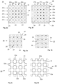
- Figs. 2a and 2b show a bottom view of an egg tray 20.
- This egg tray has a matrix pattern of five rows 21a-21e and six columns 22a-22f with cups 23, in which eggs are placed during use. Note that, because the underside of an egg tray 20 is shown here, the eggs are located on the side of the figures turned away from the side in view.
- the egg tray from Fig. 2b is shown turned through 90 degrees anticlockwise relative to the egg tray from Fig. 2a . Between the cups 23 there are raised portions 24 (in these figures, away from the viewer) which in the case of stacked egg trays 9, carry cups 23 of egg tray 20 stacked thereon.
- Figs. 3a and 3b show a top view of platform 25 for carrying and for raising and lowering egg trays.
- the flat base surface 26, and the projections 27 with their base 28 and flat upper surface 29 of the platform 25 can be seen in the top view.
- the platform 25 is shown in Figs. 3a and 3b in the same orientation with supporting points shown for an egg tray 20 that is turned 90 degrees.
- the egg trays 20 are always supplied oriented identically and it is the platform 25 that, turned 90 degrees every time, engages on the next egg trays 20.
- the platform 25 may of course also be used with stacking devices wherein egg trays 20 are supplied turned 90 degrees every time.
- Figs. 3c and 3d show a top view of platform 30 for carrying and for raising and lowering egg trays.
- the flat base surface 31 and the through holes 32 in the platform 30 can be seen in the top view.
- the holes 32a in the base surface, which in use receive cups 23 of an egg tray 20, are marked with black lines.
- the holes 32b in the base surface, which in use receive cups 23 of an egg tray 20, are marked with black lines.
- the platform 30 is shown in Figs. 3c and 3d in the same orientation with supporting points shown for an egg tray 20 that is turned 90 degrees.
- successive egg trays 20 are always supplied oriented identically and it is the platform 30 that, turned 90 degrees every time, engages on the next egg trays 20.
- the platform 30 may of course also be used with stacking devices wherein egg trays 20 are supplied turned 90 degrees every time.
- blind holes may also be provided in platform 30, which are at least formed so that cups of egg trays can be received therein.
- Fig. 4a shows a perspective bottom view (rotated 180 degrees) of the platform 25 that supports an egg tray 20 (because the arrangement is photographed upside down, the bottom ends of the eggs do not come into contact with the cups. It should be clear, however, that if the arrangement is reversed and the egg tray 20 is located on platform 25, the eggs rest in the cups 23). It can be seen in this figure that some cups 23 of the egg tray 20 rest on the flat base surface 26 of the platform 25. On their side, the projections 27 of the egg tray 20 relative to the platform 25 help centering (or vice versa), not only in the state in which the egg tray 20 rests completely on the platform 25, but certainly also while bringing the platform 25 under the egg tray 20. The upper surfaces of the projections 27 do not come into contact with the egg tray 20.
- Fig. 4b shows a perspective bottom view of a platform 30 with holes 32a, 32b extending through the platform 30 that supports an egg tray 20. It can be seen in this figure that some cups 23 of the egg tray 20 rest on the edges of holes 32a of the platform 30. The holes 32a center the cups 23 of the egg tray 20 relative to the platform 30, not only in the state in which the egg tray 20 rests completely on the platform 30, but certainly also while bringing the platform 30 under the egg tray 23.
- Fig. 5 shows a perspective view of a lifting device 40.
- the lifting device 40 has a driven guide wheel 41 rotating, or at least rotatable, about a rotation axis 50.
- the guide wheel 41 is of solid configuration in this embodiment example.
- In the side surface 44 of the guide wheel 41 there is an oval groove 45.
- a platform 25 is carried by a lifting element in the form of a rod 46. Underneath the rod 46 there is a cam wheel 47 extending at right angles to the rod 46, with cams 48, which project outwards in the plane of the cam wheel 47. Next to the side of the guide wheel 41 there is a rocker arm 49 with an axis 50 that extends at right angles to the plane of the guide wheel 41 into the oval groove 45. The rocker arm 49 is connected to a transmitting device 51 that carries the rod 46 with the cam wheel 47.
- the rocker arm 49 When guide wheel 41 rotates, the rocker arm 49 performs a rocking motion, which is converted via transmitting device 51 to a vertical up and down motion of the rod 46 with the platform 25 and the cam wheel 47.
- the slot 43 of the guide wheel 41 engages on one of the cams 48 of the cam wheel 47.
- the deflection 43b moves the respective cam 47 sideways, so that rod 46 with platform 25 is turned through 90 degrees. Then the guide wheel 41 turns further again, so that the rocker arm 49 moves the rod 46 down again via the transmitting device 51.
- Fig. 6a shows stacked egg trays 9 in side view. It can be seen in Fig. 6 that the egg trays 20 stacked on one another are oriented relative to each other turned a quarter turn, i.e. 90 degrees every time. Of the upper egg tray 20, only the outermost row 21e of eggs can be seen. In the egg tray 20 located thereunder, the outermost column 22a of eggs can be seen. In the egg tray 20 located thereunder, the outermost row (21a, not visible in Fig. 6a ) of eggs is obstructed behind the superjacent egg tray 20. In the egg tray 20 located thereunder, again an outermost column 22f of eggs is visible. The bottom egg tray is carried by a front carrier 5 and rear carrier 6, which are shown in more detail in Fig. 6b .
- Fig. 6b shows a perspective view of a carrying device 60 for carrying egg trays 20.
- the carrying device 60 has a frame 61 that supports a carrier 5. During the steps for the stacking of egg trays 20, the frame 61 moves to and fro horizontally relative to the stacked egg trays 9, as will be explained in more detail later.
- the front carrier 5 comprises a transverse beam 62 and lips 63 slanting upward, extending from the transverse beam 62.
- the lips 63 correspond in shape substantially with the raised portions (24, not shown in Fig. 6b ) on the edge of an egg tray 20.
- the slanting form of the lips 63 corresponds substantially to the angle of projections (24, not shown in Fig. 6b ) of an egg tray 20.
- the shape of the lips may be adapted to the egg trays to be carried.
- the transverse beam 62 and the outer lip 63 of front and rear carriers 5, 6 are visible.
- the lips 63 engage on inner sides of raised portions 24 of the bottom egg tray 20, so that the egg tray 20 can be carried reliably by the lips 63 over a relatively large area thereof, at least in comparison with a known device wherein the bottom egg tray 20 only rests with the underside of the edge of the egg tray 20 on a horizontal strip
- Fig. 6c shows a perspective view of a part of the packaging device 1, in which the platform 25 and the carriers 5, 6 are visible.
- the platform 25 has a smaller area than a passage that is defined by the carriers 5, 6 and by lateral edges 52, 53 of the discharge transport device 54.
- the shape of the lips 63 of carriers 5, 6 can also be seen in Fig. 6c .
- Figs. 7a-h show a side view of a packaging device 1 for eggs in successive steps during the stacking of egg trays 20. In particular, it follows the movement of egg tray 20* during the successive steps.
- Fig. 7a shows an initial state of the packaging device 1.
- the egg tray filled with eggs 20* is brought via conveyor belt (not shown in Fig. 7 ) and a first 7a and second 7b conveyor into the receiving device 3.
- the egg tray 20* just like the "next" egg tray 20 to be stacked after egg tray 20*, is oriented with the rows 21 of eggs in the longitudinal direction or transport direction of the conveyor belt.
- the platform 25 of the lifting device 40 is located at a distance directly under the egg tray 20*.
- Egg tray 20* is located directly under stacked egg trays 9.
- the orientation of the bottom egg tray 20 of the stacked egg trays is turned 90 degrees relative to egg platform 20*.
- Fig. 7b shows the next step.
- Egg tray 20* is gripped by the platform 25 on the underside and brought upward, so that the egg tray 20* engages with the upper side on the "previous" egg tray 20, stacked one cycle earlier.
- the cups 23 of the previous egg tray are supported on the raised portions 24 of egg tray 20*.
- the front 5 and rear 6 carrier under the previous egg tray 20 can now be removed, because egg tray 20* and the egg trays stacked above that are carried by the platform 25.
- Fig. 7f the platform 25 is rotated 90 degrees relative to Fig. 7d .
- Egg tray 20* is located at the bottom and is now oriented with the rows 21 of eggs at right angles to the original orientation and so also to the transport direction.
- Egg tray 20* now has the same orientation as the egg tray 20 which in Fig. 7a was located at the bottom of the stacked egg trays 9.
- the next egg tray 20 with the rows in the transport direction can be stacked under egg tray 20*.
- Fig. 7g the carriers 5,6 are moved again to their starting position and platform 25 moves downward, wherein the carriers 5, 6 engage in raised portions 24 of egg tray 20*, so that the stacked egg trays 9 are again carried reliably.
- Fig. 7h the state of the packaging device corresponds to the state that is shown in Fig. 7a , but the stack of egg trays is now stacked one layer higher, because egg tray 20* now forms the lowest egg tray.
- the cycle can now be repeated, until the desired number of egg trays 20 is stacked.
- Each cycle of steps 7a-7g is the same, at least with regard to the movements of the lifting device.
- the transverse beams 62 remain in an open state, so that the lips 63 thereof do not engage on the lowest egg tray.
- the platform 25 still rotates of course through 90 degrees after the last egg tray is placed under the already stacked egg trays 9.
- the lifting device 4 with the stacked egg trays 9 drops downward and deposits the stacked egg trays 9 on the conveyor belt, in this case the partial conveyors 7a, 7b which supplied the last (lowest) egg tray.
- the partial conveyors transport the stacked egg trays 9 further in the transport direction under the stacking device thereof, so that a new cycle can begin.
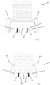
- Figs. 8a and 8b show a schematic front view of the lifting device with stacked egg trays 9, supplying an egg tray 8, or discharging stacked egg trays 9, wherein the action of the vertical elements, in this case in the form of cams 55, blocks the passage for an egg tray 8, and keeps it open for stacked egg trays 9.
- Fig. 8a shows an egg tray 8 supplied by partial conveyors 7a, 7b.
- Cams 55 extend above the partial conveyors 7a, 7b, so that they are located in the conveyor track of the egg tray 8.
- the cams 55 block egg tray 8 because they are located in the path of respective cups 23 of the egg tray.
- the partial conveyors 7a, 7b run continuously, the egg tray 8 is stationary and then, as described above, is gripped by platform 25 and is brought upward.
- platform 25 carries the stacked egg trays 9 downward in order to deposit the stacked egg trays 9 on the partial conveyors 7a, 7b, see Fig. 8b .
- the lowest egg tray is rotated 90 degrees every time after it has engaged with the egg tray located above it, the lowest egg tray is, when deposited on the partial conveyors 7a, 7b, in another orientation than during feed of said egg tray. This is clearly visible in Fig. 8b , wherein the cams 55, which are still in the same place, are positioned just between the cups 23 of the lowest egg tray. Because the partial conveyors 7a, 7b are still running, they engage on the stacked egg trays 9 and move them in the transport direction further.
Landscapes
- Engineering & Computer Science (AREA)
- Mechanical Engineering (AREA)
- Wrapping Of Specific Fragile Articles (AREA)
- Specific Conveyance Elements (AREA)
Claims (15)
- Stapelvorrichtung, die zum Stapeln von im Wesentlichen quadratischen Eierablagen (8) geeignet ist, die über einen Zuführförderer (2) in einer Zuführtransportrichtung unter einem Stapelort zugeführt werden oder zumindest zugeführt werden sollen und über einen Abführförderer (54) in einer Abführtransportrichtung vom Stapelort abgeführt werden sollen, umfassend:- eine Aufnahmevorrichtung (3), die zum sukzessiven Aufnehmen und Tragen von mit Eiern gefüllten Eierablagen (8) ausgelegt ist, die vom Zuführförderer (2) zugeführt werden, wobei die Aufnahmevorrichtung (3) einen Transitraum aufweist, der zum Bewegen einer Plattform (25) dort hindurch geeignet ist und der auf mindestens zwei Seiten durch erste Tragelemente begrenzt ist, die im Gebrauch Kanten einer Eierablage (8) tragen, die den ersten Tragelementen entsprechen,- eine am Stapelort oberhalb der Aufnahmevorrichtung (3) angeordnete Stapelvorrichtung, die einen sich im Wesentlichen in einer horizontalen Ebene erstreckenden Durchgang umfasst, der zum Transportieren der mit einer Eierablage (8) beladenen Plattform (25) dort hindurch geeignet ist und der oberhalb des Aufnahmeraums angeordnet ist und auf mindestens zwei sich parallel zueinander erstreckenden Seiten durch bewegliche zweite Tragelemente (5, 6) definiert ist, die während des Gebrauchs mit den zweiten Tragelementen (5, 6) entsprechende Kanten einer Eierablage (8) tragen und die zum Vergrößern und Verkleinern des Durchgangs ausgelegt sind,- eine Hebevorrichtung (4), die eine sich zumindest im Wesentlichen horizontal erstreckende Plattform (25) umfasst, die von einer Tragvorrichtung (60) getragen ist, die zum Bringen einer Eierablage (8) von der Aufnahmevorrichtung (3) nach oben ausgelegt ist, wobei die Plattform (25) derartige Abmessungen aufweist, dass sie durch den Transitraum und den Durchgang hindurchgehen kann,- wobei die Stapelvorrichtung dazu ausgelegt ist, eine mit Eiern gefüllte Eierablage (8), die mittels der Hebevorrichtung (4) von der Aufnahmevorrichtung (3) nach oben gebracht wurde, zu veranlassen, mit einer Oberseite der Eierablage (8) auf einer Unterseite einer weiteren in der Stapelvorrichtung angeordneten Eierablage in Eingriff zu kommen, dann die zweiten Tragelemente (5, 6) dazu zu veranlassen, sich derart zu bewegen, dass die Eierablage (8) durch den Durchgang hindurchgehen kann, dann die Hebevorrichtung (4) mit der/den so von der Plattform (25) getragenen Eierablage(n) (9) weiter nach oben zu bringen und dann die zweiten Tragelemente (5, 6) dazu zu veranlassen, den Durchgang zu verkleinern, so dass, wenn die Hebevorrichtung (4) nach unten bewegt wird, die Eierablage (8) von den zweiten Tragelementen (5, 6) getragen wird,dadurch gekennzeichnet, dass sich die zweiten Tragelemente (5, 6) zumindest im Wesentlichen horizontal und rechtwinklig zur Abführtransportrichtung erstrecken und dazu ausgelegt sind, sich in einer horizontalen Ebene in der Transportrichtung voneinander weg und zueinander hin zu bewegen.
- Stapelvorrichtung nach Anspruch 1, wobei die zweiten Tragelemente (5, 6) länglich sind.
- Stapelvorrichtung nach Anspruch 1 oder 2, wobei die zweiten Tragelemente (5, 6) eine Längsrichtung, die sich rechtwinklig zur Abführtransportrichtung erstreckt, und eine Querrichtung aufweisen, die sich von unten nach oben gesehen schräg zueinander hin erstrecken.
- Stapelvorrichtung nach einem oder mehreren der vorhergehenden Ansprüche, wobei die zweiten Tragelemente (5, 6) auf einer sich schräg nach oben erstreckenden Seite ein Profil aufweisen, das einer Innenseite einer Seitenkante einer Eierablage (8) entspricht.
- Stapelvorrichtung nach einem oder mehreren der vorhergehenden Ansprüche, wobei sich zwei erste Tragelemente in der Zuführtransportrichtung erstrecken, und/oder wobei die Plattform (25) einen rechteckigen, vorzugsweise quadratischen Umfang aufweist.
- Stapelvorrichtung nach einem oder mehreren der vorhergehenden Ansprüche, wobei der Umfang der Plattform (25) eine Länge und eine Breite aufweist, die jeweils kleiner als 400 mm sind, wobei die Länge und/oder Breite vorzugsweise kleiner als 250 mm, stärker bevorzugt kleiner als 220 mm ist.
- Stapelvorrichtung nach einem oder mehreren der vorhergehenden Ansprüche, wobei die Plattform (25) auf einer Oberseite davon mit nach oben ragenden Vorsprüngen versehen ist, die dazu ausgelegt sind, in zwei um 90 Grad um eine vertikale Achse gedrehten Positionen mit einer Unterseite einer zu tragenden Eierablage (8) in Eingriff kommen zu können.
- Stapelvorrichtung nach einem oder mehreren der vorhergehenden Ansprüche, wobei die Tragvorrichtung (60) ein sich vertikal erstreckendes längliches Hebeelement umfasst, das auf der Unterseite der Plattform (25) bereitgestellt ist, und/oder wobei die Tragvorrichtung (60) dazu ausgelegt ist, die Plattform (25) um eine vertikale Achse zu drehen.
- Stapelvorrichtung nach einem oder mehreren der vorhergehenden Ansprüche, wobei die Abführtransportvorrichtung ein Endlosband umfasst, wobei sich die Aufnahmevorrichtung (3) und/oder der Stapelort zumindest im Wesentlichen in einer horizontalen Ebene erstrecken.
- Stapelvorrichtung nach einem oder mehreren der vorhergehenden Ansprüche, wobei der Zuführförderer (2) mindestens einen ersten und einen zweiten Teilförderer umfasst, die sich in einem Abstand voneinander und parallel zueinander erstrecken, oder wobei der Zuführförderer (2) drei parallele, voneinander getrennte Bänder umfasst, die sich parallel zueinander durch einen Raum erstrecken, und wobei zwischen dem ersten und dem zweiten Teilförderer oder in den zwei Räumen zwei vertikale Elemente vorhanden sind, die in einer ersten Zuführorientierung einer Eierablage (8) als ein Anschlag für zwei Becher der Eierablage (8) dienen und die in einer zweiten Abführorientierung einer um 90 Grad relativ zur ersten Orientierung gedrehten Eierablage (8) zwischen zwei benachbarten Bechern angeordnet sind, so dass eine zugeführte Eierablage (8) durch die von der Hebevorrichtung (4) zu erfassenden vertikalen Elemente gestoppt wird und gestapelte Eierablagen (9), die von der Hebevorrichtung (4) abgelegt werden, die vertikalen Elemente ungehindert passieren können.
- Stapelvorrichtung nach Anspruch 10, umfassend mindestens den ersten und den zweiten Teilförderer, die sich in einem Abstand voneinander und parallel zueinander erstrecken, wobei die vertikalen Elemente Nocken umfassen, die derart zueinander hin klappbar sind, dass sie im geklappten Zustand ermöglichen, dass Eierablagen (8) ungehindert über den Zuführförderer(2) Richtung Abführförderer (54) passieren.
- Stapelvorrichtung nach Anspruch 10 oder 11, umfassend einen dritten Teilförderer, der dazu ausgelegt ist, zwischen dem ersten und zweiten Teilförderer platziert zu sein, um ein zumindest im Wesentlichen durchgehendes Förderband zu bilden, das sich quer zu einer Transportrichtung des Zuführförderers (2) erstreckt.
- Stapelvorrichtung nach den Ansprüchen 11 und 12, wobei die vertikalen Elemente im genannten zueinander hin geklappten Zustand unter der Höhe der Bänder der Teilförderer angeordnet sind.
- Verfahren zum Stapeln von Eierablagen (8), das die folgenden Schritte umfasst:- Zuführen einer mit Eiern gefüllten Eierablage (8) zu einer Aufnahmevorrichtung (3), die unter einem Stapelort einer Stapelvorrichtung angeordnet ist und einen Durchgang umfasst, wobei die Aufnahmevorrichtung (3) einen Transitraum aufweist, der zum Bewegen einer Plattform (25) dort hindurch geeignet ist und der auf mindestens zwei Seiten durch erste Tragelemente definiert ist, die im Gebrauch Kanten einer Eierablage (8) tragen, die den ersten Tragelementen entsprechen,- Bewegen der Eierablage (8) nach oben in Richtung der Stapelvorrichtung mittels einer Hebevorrichtung (4), die eine sich zumindest im Wesentlichen horizontal erstreckende, von einer Tragvorrichtung (60) getragene Plattform (25) mit derartigen Abmessungen umfasst, dass sie durch den Transitraum und den Durchgang hindurchgehen kann,- Transportieren der mit einer Eierablage (8) beladenen Plattform (25) durch den Durchgang, wobei der Durchgang auf mindestens zwei sich parallel zueinander erstreckenden Seiten durch bewegliche zweite Tragelemente (5, 6) definiert ist, um Kanten einer Eierablage (8) zu tragen, die den zweiten Tragelementen (5, 6) entsprechen,- Veranlassen, dass die mit Eiern gefüllte, mittels der Hebevorrichtung (4) nach oben gebrachte Eierablage (8) mit einer Oberseite der Eierablage (8) auf einer Unterseite einer weiteren in der Stapelvorrichtung angeordneten Eierablage (9) in Eingriff kommt,- Veranlassen, dass sich die zweiten Tragelemente (5, 6) derart bewegen, dass die Eierablage (8) durch den Durchgang hindurchgehen kann,- mittels der Hebevorrichtung (4), Bringen der von der Plattform (25) getragenen Eierablage (8) weiter nach oben,- Verkleinern des Durchgangs mittels der zweiten Tragelemente (5, 6),- Bewegen der Hebevorrichtung (4) nach unten, und Überführen der Eierablage (8) auf die zweiten Tragelemente (5, 6), so dass sie von den zweiten Tragelementen (5, 6) getragen wird,dadurch gekennzeichnet, dass sich die zweiten Tragelemente (5, 6) zumindest im Wesentlichen horizontal und rechtwinklig zur Abführtransportrichtung erstrecken und sich zum Vergrößern und Verkleinern des Durchgangs in einer horizontalen Ebene in der Transportrichtung voneinander weg und zueinander hin bewegen.
- Verfahren nach Anspruch 14, wobei die Eierablagen (8) mittels einer Stapelvorrichtung nach einem oder mehreren der Ansprüche 1 bis 13 gestapelt werden.
Applications Claiming Priority (2)
| Application Number | Priority Date | Filing Date | Title |
|---|---|---|---|
| NL2031793A NL2031793B1 (nl) | 2022-05-06 | 2022-05-06 | Stapelinrichting voor eiertrays |
| PCT/NL2023/050245 WO2023214878A1 (en) | 2022-05-06 | 2023-05-08 | Stacking device for egg trays |
Publications (3)
| Publication Number | Publication Date |
|---|---|
| EP4433396A1 EP4433396A1 (de) | 2024-09-25 |
| EP4433396C0 EP4433396C0 (de) | 2025-03-19 |
| EP4433396B1 true EP4433396B1 (de) | 2025-03-19 |
Family
ID=83188598
Family Applications (1)
| Application Number | Title | Priority Date | Filing Date |
|---|---|---|---|
| EP23723094.1A Active EP4433396B1 (de) | 2022-05-06 | 2023-05-08 | Stapelvorrichtung für eierschalen |
Country Status (8)
| Country | Link |
|---|---|
| US (1) | US20250320011A1 (de) |
| EP (1) | EP4433396B1 (de) |
| CN (1) | CN119325448A (de) |
| CA (1) | CA3252420A1 (de) |
| ES (1) | ES3028428T3 (de) |
| NL (1) | NL2031793B1 (de) |
| PL (1) | PL4433396T3 (de) |
| WO (1) | WO2023214878A1 (de) |
Families Citing this family (1)
| Publication number | Priority date | Publication date | Assignee | Title |
|---|---|---|---|---|
| CN117383268A (zh) * | 2023-11-30 | 2024-01-12 | 江苏宏盛景智能装备有限公司 | 一种机器人码卸盘机的辅助供料装置 |
Family Cites Families (10)
| Publication number | Priority date | Publication date | Assignee | Title |
|---|---|---|---|---|
| US3643817A (en) * | 1970-09-16 | 1972-02-22 | Fmc Corp | Combination stacker-feeder |
| US4787799A (en) * | 1986-09-12 | 1988-11-29 | Kornelis Platteschorre | Egg carton stacking-loading device and method |
| US4995785A (en) * | 1986-09-12 | 1991-02-26 | Kornelis Platteschorre | Egg carton stacking-loading device and method |
| IT1234246B (it) * | 1988-04-13 | 1992-05-13 | Ima Spa | Dispositivo per la formazione, dal basso verso l'alto, di una pila di blister |
| US5232080A (en) * | 1989-03-10 | 1993-08-03 | Fps Food Processing Systems B.V. | Article handling method and apparatus |
| JP5253771B2 (ja) * | 2007-07-25 | 2013-07-31 | 株式会社東芝 | トレイ保持装置 |
| PL2766264T3 (pl) * | 2011-10-10 | 2016-04-29 | Moba Group Bv | Głowica zaciskowa do palet |
| EP4065473A4 (de) * | 2019-11-27 | 2024-06-19 | Punchbowl Automation IP Limited | Vorrichtung und verfahren zum verschliessen und stapeln von kartons |
| KR102227568B1 (ko) * | 2020-04-10 | 2021-03-11 | 은 식 신 | 계란판 자동 적층장치 |
| KR102507257B1 (ko) * | 2020-07-16 | 2023-03-06 | 은 식 신 | 포장 계란판 자동 적층장치, 이를 구비한 계란판에 라벨 자동 부착형 상판 캡슐 포장 장치 |
-
2022
- 2022-05-06 NL NL2031793A patent/NL2031793B1/nl active
-
2023
- 2023-05-08 CA CA3252420A patent/CA3252420A1/en active Pending
- 2023-05-08 US US18/863,273 patent/US20250320011A1/en active Pending
- 2023-05-08 EP EP23723094.1A patent/EP4433396B1/de active Active
- 2023-05-08 PL PL23723094.1T patent/PL4433396T3/pl unknown
- 2023-05-08 WO PCT/NL2023/050245 patent/WO2023214878A1/en not_active Ceased
- 2023-05-08 CN CN202380045419.6A patent/CN119325448A/zh active Pending
- 2023-05-08 ES ES23723094T patent/ES3028428T3/es active Active
Also Published As
| Publication number | Publication date |
|---|---|
| WO2023214878A1 (en) | 2023-11-09 |
| EP4433396A1 (de) | 2024-09-25 |
| US20250320011A1 (en) | 2025-10-16 |
| NL2031793B1 (nl) | 2023-11-14 |
| CN119325448A (zh) | 2025-01-17 |
| ES3028428T3 (en) | 2025-06-19 |
| EP4433396C0 (de) | 2025-03-19 |
| PL4433396T3 (pl) | 2025-06-09 |
| CA3252420A1 (en) | 2023-11-09 |
Similar Documents
| Publication | Publication Date | Title |
|---|---|---|
| EP2773564B1 (de) | Becherzuführer | |
| EP2393736B1 (de) | Verfahren und vorrichtung zum sammeln verschiedener produkte, die teil eines auftrags bilden | |
| EP4520689A2 (de) | Lagerbehälter für automatisiertes regalbediensystem | |
| EP2397428B1 (de) | Vorrichtung und Verfahren zum Stapeln von Verpackungseinheiten | |
| ES2303865T3 (es) | Dispositivo para el apilado o desapilado de objetos. | |
| US6264422B1 (en) | Apparatus and method for assembling items onto a pallet | |
| EP4433396B1 (de) | Stapelvorrichtung für eierschalen | |
| JP2025063258A (ja) | 荷下ろし構成体および荷下ろしステーション、ならびに、保管コンテナからアイテムを降ろす方法 | |
| NL1010468C2 (nl) | Inrichting en werkwijze voor het automatisch stapelen van producten op een pallet. | |
| EP4433397B1 (de) | Hebevorrichtung für eiertragplatten | |
| US11161635B2 (en) | Egg-orienting station for orienting eggs, and apparatus for transporting and packaging eggs | |
| WO2003106316A1 (en) | Contoured palletizer layer pad | |
| CN110254860B (zh) | 一种装箱方法 | |
| US6305526B1 (en) | Ampule transfer unit | |
| CA3117120A1 (en) | Storage container for automated storage and retrieval system | |
| EP2172398B1 (de) | Vorrichtung zum Stapeln mehrerer plattenförmiger Produkte | |
| GB2078650A (en) | Storage tower for vehicle panels | |
| JP2006347753A (ja) | 搬送システム | |
| JP7670339B2 (ja) | 鍔付き容器の処理装置 | |
| EP4349722A1 (de) | Verfahren und system zum plazieren von produkten in kisten | |
| JP3758716B2 (ja) | 円錐台形状容器の集積・段積方法 | |
| WO2007039511A1 (en) | Method for lifting up punnets containing horticultural products from the corresponding conveyance trays | |
| HK40118634A (en) | Storage container for automated storage and retrieval system | |
| JP2002249202A (ja) | 搬送保管装置 | |
| EP1271431A3 (de) | Verkaufsautomat für verpackte Produkte |
Legal Events
| Date | Code | Title | Description |
|---|---|---|---|
| STAA | Information on the status of an ep patent application or granted ep patent |
Free format text: STATUS: UNKNOWN |
|
| STAA | Information on the status of an ep patent application or granted ep patent |
Free format text: STATUS: THE INTERNATIONAL PUBLICATION HAS BEEN MADE |
|
| PUAI | Public reference made under article 153(3) epc to a published international application that has entered the european phase |
Free format text: ORIGINAL CODE: 0009012 |
|
| STAA | Information on the status of an ep patent application or granted ep patent |
Free format text: STATUS: REQUEST FOR EXAMINATION WAS MADE |
|
| 17P | Request for examination filed |
Effective date: 20240617 |
|
| AK | Designated contracting states |
Kind code of ref document: A1 Designated state(s): AL AT BE BG CH CY CZ DE DK EE ES FI FR GB GR HR HU IE IS IT LI LT LU LV MC ME MK MT NL NO PL PT RO RS SE SI SK SM TR |
|
| GRAP | Despatch of communication of intention to grant a patent |
Free format text: ORIGINAL CODE: EPIDOSNIGR1 |
|
| STAA | Information on the status of an ep patent application or granted ep patent |
Free format text: STATUS: GRANT OF PATENT IS INTENDED |
|
| INTG | Intention to grant announced |
Effective date: 20241031 |
|
| GRAS | Grant fee paid |
Free format text: ORIGINAL CODE: EPIDOSNIGR3 |
|
| GRAA | (expected) grant |
Free format text: ORIGINAL CODE: 0009210 |
|
| STAA | Information on the status of an ep patent application or granted ep patent |
Free format text: STATUS: THE PATENT HAS BEEN GRANTED |
|
| DAV | Request for validation of the european patent (deleted) | ||
| DAX | Request for extension of the european patent (deleted) | ||
| AK | Designated contracting states |
Kind code of ref document: B1 Designated state(s): AL AT BE BG CH CY CZ DE DK EE ES FI FR GB GR HR HU IE IS IT LI LT LU LV MC ME MK MT NL NO PL PT RO RS SE SI SK SM TR |
|
| REG | Reference to a national code |
Ref country code: GB Ref legal event code: FG4D |
|
| REG | Reference to a national code |
Ref country code: CH Ref legal event code: EP |
|
| REG | Reference to a national code |
Ref country code: IE Ref legal event code: FG4D |
|
| REG | Reference to a national code |
Ref country code: DE Ref legal event code: R096 Ref document number: 602023002510 Country of ref document: DE |
|
| U01 | Request for unitary effect filed |
Effective date: 20250422 |
|
| U07 | Unitary effect registered |
Designated state(s): AT BE BG DE DK EE FI FR IT LT LU LV MT NL PT RO SE SI Effective date: 20250512 |
|
| REG | Reference to a national code |
Ref country code: ES Ref legal event code: FG2A Ref document number: 3028428 Country of ref document: ES Kind code of ref document: T3 Effective date: 20250619 |
|
| U20 | Renewal fee for the european patent with unitary effect paid |
Year of fee payment: 3 Effective date: 20250528 |
|
| PG25 | Lapsed in a contracting state [announced via postgrant information from national office to epo] |
Ref country code: RS Free format text: LAPSE BECAUSE OF FAILURE TO SUBMIT A TRANSLATION OF THE DESCRIPTION OR TO PAY THE FEE WITHIN THE PRESCRIBED TIME-LIMIT Effective date: 20250619 |
|
| PGFP | Annual fee paid to national office [announced via postgrant information from national office to epo] |
Ref country code: PL Payment date: 20250512 Year of fee payment: 3 |
|
| PG25 | Lapsed in a contracting state [announced via postgrant information from national office to epo] |
Ref country code: NO Free format text: LAPSE BECAUSE OF FAILURE TO SUBMIT A TRANSLATION OF THE DESCRIPTION OR TO PAY THE FEE WITHIN THE PRESCRIBED TIME-LIMIT Effective date: 20250619 |
|
| PG25 | Lapsed in a contracting state [announced via postgrant information from national office to epo] |
Ref country code: HR Free format text: LAPSE BECAUSE OF FAILURE TO SUBMIT A TRANSLATION OF THE DESCRIPTION OR TO PAY THE FEE WITHIN THE PRESCRIBED TIME-LIMIT Effective date: 20250319 |
|
| PG25 | Lapsed in a contracting state [announced via postgrant information from national office to epo] |
Ref country code: GR Free format text: LAPSE BECAUSE OF FAILURE TO SUBMIT A TRANSLATION OF THE DESCRIPTION OR TO PAY THE FEE WITHIN THE PRESCRIBED TIME-LIMIT Effective date: 20250620 |
|
| PGFP | Annual fee paid to national office [announced via postgrant information from national office to epo] |
Ref country code: TR Payment date: 20250610 Year of fee payment: 3 |
|
| PG25 | Lapsed in a contracting state [announced via postgrant information from national office to epo] |
Ref country code: SM Free format text: LAPSE BECAUSE OF FAILURE TO SUBMIT A TRANSLATION OF THE DESCRIPTION OR TO PAY THE FEE WITHIN THE PRESCRIBED TIME-LIMIT Effective date: 20250319 |
|
| PGFP | Annual fee paid to national office [announced via postgrant information from national office to epo] |
Ref country code: ES Payment date: 20250630 Year of fee payment: 3 |
|
| PG25 | Lapsed in a contracting state [announced via postgrant information from national office to epo] |
Ref country code: CZ Free format text: LAPSE BECAUSE OF FAILURE TO SUBMIT A TRANSLATION OF THE DESCRIPTION OR TO PAY THE FEE WITHIN THE PRESCRIBED TIME-LIMIT Effective date: 20250319 |
|
| PG25 | Lapsed in a contracting state [announced via postgrant information from national office to epo] |
Ref country code: SK Free format text: LAPSE BECAUSE OF FAILURE TO SUBMIT A TRANSLATION OF THE DESCRIPTION OR TO PAY THE FEE WITHIN THE PRESCRIBED TIME-LIMIT Effective date: 20250319 |
|
| PG25 | Lapsed in a contracting state [announced via postgrant information from national office to epo] |
Ref country code: IS Free format text: LAPSE BECAUSE OF FAILURE TO SUBMIT A TRANSLATION OF THE DESCRIPTION OR TO PAY THE FEE WITHIN THE PRESCRIBED TIME-LIMIT Effective date: 20250719 |
|
| PLBE | No opposition filed within time limit |
Free format text: ORIGINAL CODE: 0009261 |
|
| STAA | Information on the status of an ep patent application or granted ep patent |
Free format text: STATUS: NO OPPOSITION FILED WITHIN TIME LIMIT |
|
| REG | Reference to a national code |
Ref country code: CH Ref legal event code: L10 Free format text: ST27 STATUS EVENT CODE: U-0-0-L10-L00 (AS PROVIDED BY THE NATIONAL OFFICE) Effective date: 20260128 |
|
| PG25 | Lapsed in a contracting state [announced via postgrant information from national office to epo] |
Ref country code: MC Free format text: LAPSE BECAUSE OF FAILURE TO SUBMIT A TRANSLATION OF THE DESCRIPTION OR TO PAY THE FEE WITHIN THE PRESCRIBED TIME-LIMIT Effective date: 20250319 |
|
| 26N | No opposition filed |
Effective date: 20251222 |
|
| PG25 | Lapsed in a contracting state [announced via postgrant information from national office to epo] |
Ref country code: IE Free format text: LAPSE BECAUSE OF NON-PAYMENT OF DUE FEES Effective date: 20250508 |