EP4431856A1 - Micro-channel heat exchanger and heat pump system having the same - Google Patents
Micro-channel heat exchanger and heat pump system having the same Download PDFInfo
- Publication number
- EP4431856A1 EP4431856A1 EP24161809.9A EP24161809A EP4431856A1 EP 4431856 A1 EP4431856 A1 EP 4431856A1 EP 24161809 A EP24161809 A EP 24161809A EP 4431856 A1 EP4431856 A1 EP 4431856A1
- Authority
- EP
- European Patent Office
- Prior art keywords
- micro
- channel
- heat exchange
- heat exchanger
- manifold
- Prior art date
- Legal status (The legal status is an assumption and is not a legal conclusion. Google has not performed a legal analysis and makes no representation as to the accuracy of the status listed.)
- Pending
Links
Images



Classifications
-
- F—MECHANICAL ENGINEERING; LIGHTING; HEATING; WEAPONS; BLASTING
- F28—HEAT EXCHANGE IN GENERAL
- F28D—HEAT-EXCHANGE APPARATUS, NOT PROVIDED FOR IN ANOTHER SUBCLASS, IN WHICH THE HEAT-EXCHANGE MEDIA DO NOT COME INTO DIRECT CONTACT
- F28D1/00—Heat-exchange apparatus having stationary conduit assemblies for one heat-exchange medium only, the media being in contact with different sides of the conduit wall, in which the other heat-exchange medium is a large body of fluid, e.g. domestic or motor car radiators
- F28D1/02—Heat-exchange apparatus having stationary conduit assemblies for one heat-exchange medium only, the media being in contact with different sides of the conduit wall, in which the other heat-exchange medium is a large body of fluid, e.g. domestic or motor car radiators with heat-exchange conduits immersed in the body of fluid
- F28D1/04—Heat-exchange apparatus having stationary conduit assemblies for one heat-exchange medium only, the media being in contact with different sides of the conduit wall, in which the other heat-exchange medium is a large body of fluid, e.g. domestic or motor car radiators with heat-exchange conduits immersed in the body of fluid with tubular conduits
- F28D1/053—Heat-exchange apparatus having stationary conduit assemblies for one heat-exchange medium only, the media being in contact with different sides of the conduit wall, in which the other heat-exchange medium is a large body of fluid, e.g. domestic or motor car radiators with heat-exchange conduits immersed in the body of fluid with tubular conduits the conduits being straight
- F28D1/0535—Heat-exchange apparatus having stationary conduit assemblies for one heat-exchange medium only, the media being in contact with different sides of the conduit wall, in which the other heat-exchange medium is a large body of fluid, e.g. domestic or motor car radiators with heat-exchange conduits immersed in the body of fluid with tubular conduits the conduits being straight the conduits having a non-circular cross-section
- F28D1/05366—Assemblies of conduits connected to common headers, e.g. core type radiators
- F28D1/05383—Assemblies of conduits connected to common headers, e.g. core type radiators with multiple rows of conduits or with multi-channel conduits
-
- F—MECHANICAL ENGINEERING; LIGHTING; HEATING; WEAPONS; BLASTING
- F28—HEAT EXCHANGE IN GENERAL
- F28F—DETAILS OF HEAT-EXCHANGE AND HEAT-TRANSFER APPARATUS, OF GENERAL APPLICATION
- F28F1/00—Tubular elements; Assemblies of tubular elements
- F28F1/10—Tubular elements and assemblies thereof with means for increasing heat-transfer area, e.g. with fins, with projections, with recesses
- F28F1/12—Tubular elements and assemblies thereof with means for increasing heat-transfer area, e.g. with fins, with projections, with recesses the means being only outside the tubular element
- F28F1/126—Tubular elements and assemblies thereof with means for increasing heat-transfer area, e.g. with fins, with projections, with recesses the means being only outside the tubular element consisting of zig-zag shaped fins
- F28F1/128—Fins with openings, e.g. louvered fins
-
- F—MECHANICAL ENGINEERING; LIGHTING; HEATING; WEAPONS; BLASTING
- F28—HEAT EXCHANGE IN GENERAL
- F28D—HEAT-EXCHANGE APPARATUS, NOT PROVIDED FOR IN ANOTHER SUBCLASS, IN WHICH THE HEAT-EXCHANGE MEDIA DO NOT COME INTO DIRECT CONTACT
- F28D7/00—Heat-exchange apparatus having stationary tubular conduit assemblies for both heat-exchange media, the media being in contact with different sides of a conduit wall
- F28D7/16—Heat-exchange apparatus having stationary tubular conduit assemblies for both heat-exchange media, the media being in contact with different sides of a conduit wall the conduits being arranged in parallel spaced relation
-
- F—MECHANICAL ENGINEERING; LIGHTING; HEATING; WEAPONS; BLASTING
- F28—HEAT EXCHANGE IN GENERAL
- F28F—DETAILS OF HEAT-EXCHANGE AND HEAT-TRANSFER APPARATUS, OF GENERAL APPLICATION
- F28F1/00—Tubular elements; Assemblies of tubular elements
- F28F1/10—Tubular elements and assemblies thereof with means for increasing heat-transfer area, e.g. with fins, with projections, with recesses
- F28F1/12—Tubular elements and assemblies thereof with means for increasing heat-transfer area, e.g. with fins, with projections, with recesses the means being only outside the tubular element
- F28F1/14—Tubular elements and assemblies thereof with means for increasing heat-transfer area, e.g. with fins, with projections, with recesses the means being only outside the tubular element and extending longitudinally
- F28F1/16—Tubular elements and assemblies thereof with means for increasing heat-transfer area, e.g. with fins, with projections, with recesses the means being only outside the tubular element and extending longitudinally the means being integral with the element, e.g. formed by extrusion
- F28F1/18—Tubular elements and assemblies thereof with means for increasing heat-transfer area, e.g. with fins, with projections, with recesses the means being only outside the tubular element and extending longitudinally the means being integral with the element, e.g. formed by extrusion the element being built-up from finned sections
-
- F—MECHANICAL ENGINEERING; LIGHTING; HEATING; WEAPONS; BLASTING
- F28—HEAT EXCHANGE IN GENERAL
- F28F—DETAILS OF HEAT-EXCHANGE AND HEAT-TRANSFER APPARATUS, OF GENERAL APPLICATION
- F28F1/00—Tubular elements; Assemblies of tubular elements
- F28F1/10—Tubular elements and assemblies thereof with means for increasing heat-transfer area, e.g. with fins, with projections, with recesses
- F28F1/12—Tubular elements and assemblies thereof with means for increasing heat-transfer area, e.g. with fins, with projections, with recesses the means being only outside the tubular element
- F28F1/24—Tubular elements and assemblies thereof with means for increasing heat-transfer area, e.g. with fins, with projections, with recesses the means being only outside the tubular element and extending transversely
- F28F1/32—Tubular elements and assemblies thereof with means for increasing heat-transfer area, e.g. with fins, with projections, with recesses the means being only outside the tubular element and extending transversely the means having portions engaging further tubular elements
- F28F1/325—Fins with openings
-
- F—MECHANICAL ENGINEERING; LIGHTING; HEATING; WEAPONS; BLASTING
- F28—HEAT EXCHANGE IN GENERAL
- F28F—DETAILS OF HEAT-EXCHANGE AND HEAT-TRANSFER APPARATUS, OF GENERAL APPLICATION
- F28F17/00—Removing ice or water from heat-exchange apparatus
- F28F17/005—Means for draining condensates from heat exchangers, e.g. from evaporators
-
- F—MECHANICAL ENGINEERING; LIGHTING; HEATING; WEAPONS; BLASTING
- F28—HEAT EXCHANGE IN GENERAL
- F28F—DETAILS OF HEAT-EXCHANGE AND HEAT-TRANSFER APPARATUS, OF GENERAL APPLICATION
- F28F9/00—Casings; Header boxes; Auxiliary supports for elements; Auxiliary members within casings
- F28F9/22—Arrangements for directing heat-exchange media into successive compartments, e.g. arrangements of guide plates
-
- F—MECHANICAL ENGINEERING; LIGHTING; HEATING; WEAPONS; BLASTING
- F28—HEAT EXCHANGE IN GENERAL
- F28F—DETAILS OF HEAT-EXCHANGE AND HEAT-TRANSFER APPARATUS, OF GENERAL APPLICATION
- F28F1/00—Tubular elements; Assemblies of tubular elements
- F28F1/02—Tubular elements of cross-section which is non-circular
- F28F1/022—Tubular elements of cross-section which is non-circular with multiple channels
-
- F—MECHANICAL ENGINEERING; LIGHTING; HEATING; WEAPONS; BLASTING
- F28—HEAT EXCHANGE IN GENERAL
- F28F—DETAILS OF HEAT-EXCHANGE AND HEAT-TRANSFER APPARATUS, OF GENERAL APPLICATION
- F28F2260/00—Heat exchangers or heat exchange elements having special size, e.g. microstructures
- F28F2260/02—Heat exchangers or heat exchange elements having special size, e.g. microstructures having microchannels
-
- F—MECHANICAL ENGINEERING; LIGHTING; HEATING; WEAPONS; BLASTING
- F28—HEAT EXCHANGE IN GENERAL
- F28F—DETAILS OF HEAT-EXCHANGE AND HEAT-TRANSFER APPARATUS, OF GENERAL APPLICATION
- F28F2265/00—Safety or protection arrangements; Arrangements for preventing malfunction
- F28F2265/06—Safety or protection arrangements; Arrangements for preventing malfunction by using means for draining heat exchange media from heat exchangers
-
- F—MECHANICAL ENGINEERING; LIGHTING; HEATING; WEAPONS; BLASTING
- F28—HEAT EXCHANGE IN GENERAL
- F28F—DETAILS OF HEAT-EXCHANGE AND HEAT-TRANSFER APPARATUS, OF GENERAL APPLICATION
- F28F2265/00—Safety or protection arrangements; Arrangements for preventing malfunction
- F28F2265/22—Safety or protection arrangements; Arrangements for preventing malfunction for draining
Definitions
- the present invention relates to the technical field of heat exchange, in particular to a micro-channel heat exchanger, and further to a heat pump system configured with the micro-channel heat exchanger.
- Micro-Channel Heat Exchanger is a heat exchanger with a channel having an equivalent diameter ranging from 10 to 1000 ⁇ m. This kind of heat exchanger has dozens of fine flow channels inside its flat tube. Both ends of the flat tube are connected to a cylindrical manifold, where a partition is arranged inside the manifold to separate the flow channel of the micro-channel heat exchanger into several flow paths.
- a micro-channel heat exchanger 10 typically includes an inlet manifold 11, an outlet manifold 12, a plurality of flat tubes 13 in connection with these manifolds, and a plurality of heat exchange fins 14.
- Each flat tube 13 has micro-channels or small paths for refrigerant, such as gas, liquid, or gas-liquid two-phase fluid, to pass through.
- refrigerant such as gas, liquid, or gas-liquid two-phase fluid
- the refrigerant After heat exchange with the external fluid, the refrigerant leaves the flat tube 13 and enters the outlet manifold 12, and then leaves the outlet manifold 12 through the outlet of the outlet manifold 12.
- an additional heat dissipation structure such as a louver structure, is usually added to the surface of the heat exchange fin 14.
- the surface temperature of the heat exchange fin 14 is lower than the dew point temperature of the ambient air, so the water vapor contained in the air will precipitate from the surface of the heat exchange fin 14. Due to gravity, water droplets gradually flow to the bottom of the heat exchange fins 14.
- the present invention provides a micro-channel heat exchanger, so as to solve or at least alleviate one or more of the aforementioned problems and problems in other aspects existing in the prior art, or to provide an alternative technical solution for the prior art.
- each of the plurality of heat exchange fins below the bottommost micro-channel flat tube may be provided with a guiding structure, and the guiding structure may have smooth planes on both sides.
- the guiding structure may be the lower surface of the bottommost micro-channel flat tube.
- the area of the portions of the plurality of heat exchange fins below the bottommost micro-channel flat tube may gradually increase towards the side of the drainage groove.
- the bottom of the guiding structure may have a bent, curved, linear or non-linear contour.
- the heat dissipation structure for increasing the heat exchange area may be at least one of a strip structure, a corrugated structure, a staggered teeth structure, a louver structure, a structure with openings, a structure with protrusions, or a structure with grooves on the surface.
- the plurality of heat exchange fins may be of the same size and shape, and may be spaced apart from each other at the same distance.
- the plurality of heat exchange fins may be made of aluminum alloy.
- the micro-channel heat exchanger may be a condenser or an evaporator.
- a heat pump system comprising the aforementioned micro-channel heat exchanger is provided.
- micro-channel heat exchanger of the present invention adopts a specially designed guiding structure, which can ensure heat exchange efficiency while preventing accumulation of condensed water on the heat exchange fins, thereby improving the overall performance of the micro-channel heat exchanger.
- orientation terms mentioned or possibly mentioned in the present invention such as up, down, left, right, front, back, inner side, outer side, front side, top, bottom, etc., are defined relative to the structures shown in the respective drawings, and they are relative concepts. Therefore, they may vary accordingly according to their different positions and usage states. Therefore, these or other orientation terms should not be interpreted as restrictive terms.
- references to the terms “one embodiment”, “some embodiments”, “examples”, “specific examples”, or “some examples” means that the specific features, structures, materials, or features described in conjunction with the embodiment(s) or example(s) are included in at least one embodiment or example of the embodiments of the present invention.
- the illustrative expressions for the above terms do not necessarily refer to the same embodiment(s) or example(s).
- the specific characteristics, structures, materials, or features described can be combined in an appropriate manner in any one or more embodiments or examples.
- those skilled in the art may combine the different embodiments or examples described in the present invention, as well as the features of the different embodiments or examples, without conflicting with each other.
- connection can be a fixed connection, a detachable connection, or an integral connection. It can be a mechanical connection or an electrical connection. It can be a direct connection or an indirect connection through an intermediate medium. It can be the internal connection of two components or the interaction relationship between two components, unless otherwise specified.
- fix can be a fixed connection, a detachable connection, or an integral connection. It can be a mechanical connection or an electrical connection. It can be a direct connection or an indirect connection through an intermediate medium. It can be the internal connection of two components or the interaction relationship between two components, unless otherwise specified.
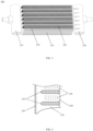
- FIG. 3 schematically illustrates the structure of an embodiment of a micro-channel heat exchanger of the present invention in general.
- the micro-channel heat exchanger 100 is composed of a first manifold 110, a second manifold 120, a plurality of micro-channel flat tubes 130, and a plurality of heat exchange fins 140, and other parts.
- the first manifold 110 and the second manifold 120 are spaced apart, with one serving as the inlet manifold and the other as the outlet manifold.
- the plurality of micro-channel flat tubes 130 are sequentially connected from top to bottom between the first manifold 110 and the second manifold 120, and the plurality of heat exchange fins 140 are spaced at a predetermined distance from each other and formed with tube holes for the plurality of micro-channel flat tubes 130 to pass through.
- Refrigerant or coolant flows inside the plurality of micro-channel flat tubes 130, while fluid medium, such as air, flows outside the micro-channel flat tubes 130. Heat conduction is carried out between the refrigerant and air through the tube walls and heat exchange fins 140, thereby achieving heat exchange.
- the plurality of heat exchange fins 140 are additionally configured with heat dissipation structures 150, which are located above the micro-channel flat tubes, so that more fluid medium can pass through the heat exchanger of the same size, thereby achieving higher heat exchange efficiency and heat transfer coefficient.
- a drainage groove 160 is vertically arranged on the same side of the plurality of heat exchange fins 140.
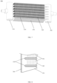
- the portions of the at least one of the plurality of heat exchange fins 140 below the bottommost micro-channel flat tube is provided with a guiding structure 170, which is used to guide water droplets condensed on the surface of the at least one heat exchange fin to the drainage groove 160, thereby avoiding the accumulation of condensed water on the surface of the heat exchange fin at its bottom.
- the guiding structure 170 can be the portion of each of the plurality of heat exchange fins 140 below the bottommost micro-channel flat tube, and the guiding structure 170 has smooth planes on both sides.
- the bottom portions of the plurality of heat exchange fins 140 are not provided with additional heat dissipation structures, such a design, however, can effectively prevent condensed water from accumulating in that area, so as to not affect the overall heat exchange efficiency.
- the contour of the bottom of the guiding structure 170 is linear and is parallel to the contour of the bottom of the micro-channel flat tube 130, so that the guiding structure 170 forms a substantially rectangular shape.
- guiding structures on each of the plurality of heat exchange fins 140 it is also feasible to configure guiding structures on specific heat exchange fins among the plurality of heat exchange fins 140. For example, guiding structures are only configured on the leftmost and rightmost heat exchange fins of the plurality of heat exchange fins.
- the area of the portions of the plurality of heat exchange fins below the bottommost micro-channel flat tube i.e., the area of the guiding structure
- the bottom of the guiding structure has a bent, curved, linear, or non-linear contour.
- the bottom of the guiding structure 270 has a curved contour.
- the first manifold 210, the second manifold 220, the plurality of micro-channel flat tubes 230, the plurality of heat exchange fins 240, the heat dissipation structures 250, and the drainage groove 260 and other parts in the micro-channel heat exchanger 200 can refer to the aforementioned embodiments, which will not be repeated here.
- the bottom of the guiding structure 370 has a linear contour.
- FIGS. 9 and 10 schematically illustrate the structure of another embodiment of the micro-channel heat exchanger of the present invention.
- the guiding structure 470 is the lower surface of the bottommost micro-channel flat tube 430, thereby reducing the risk of accumulation of water droplets below the bottommost micro-channel flat tube.
- the first manifold 410, the second manifold 420, the plurality of micro-channel flat tubes 430, the plurality of heat exchange fins 440, the heat dissipation structures 450, and the drainage groove 460 and other parts in the micro-channel heat exchanger 400 can refer to the aforementioned embodiments, which will not be repeated here.
- the heat dissipation structure 150 used to increase the heat exchange area can be constructed as a solid or hollow strip structure, a corrugated structure, a staggered teeth structure, a louver structure, a structure with openings, a structure with protrusions, or a structure with grooves on the surface, or other similar structures, which is conducive to further increasing the contact area between the fin body and the fluid medium, thereby achieving greater heat transfer efficiency.
- the plurality of heat exchange fins 140 can be designed to be of the same size and shape, and spaced from each other at the same distance, so as to improve the heat exchange area and efficiency of the micro-channel heat exchanger.
- the heat exchange fins 140 can be made of aluminum alloy. Those skilled in the art are aware that aluminum materials have good processability and good heat exchange performance.
- the present invention also provides a heat pump system.
- the heat pump system typically has multiple operating modes, including the cooling mode, heating mode, and dehumidification mode (also known as defogging mode).
- the heat pump system mainly includes a coolant circulation circuit and a water circuit.
- the coolant circulation circuit is sequentially provided with a compressor, an indoor heat exchanger, a throttling device, and an outdoor heat exchanger, wherein, both the indoor and outdoor heat exchangers can be in the form of a micro-channel heat exchanger according to the present invention.
- the coolant In the heating mode, the coolant is compressed into high-temperature and high-pressure gas through the compressor, and the high-temperature and high-pressure gas enters the indoor heat exchanger for heat exchange with circulating water to heat the water. After passing through the indoor heat exchanger, the coolant is further throttled by the throttling device to form a low-temperature and low-pressure liquid (or gas-liquid mixed refrigerant).
- the low-temperature and low-pressure liquid refrigerant evaporates in the outdoor heat exchanger, absorbs heat from the outside air, and converts into a gaseous refrigerant.
- the gaseous refrigerant can return to the compressor further using a gas-liquid separator or other means when necessary, thus completing the coolant circulation circuit.
- the indoor heat exchanger is a condenser
- the outdoor heat exchanger is an evaporator.
- the coolant In the cooling mode, the coolant is compressed into high-temperature and high-pressure gas through the compressor, and the high-temperature and high-pressure gas enters the outdoor heat exchanger for heat exchange with air, etc., thus becoming a medium-temperature and high-pressure gas.
- the coolant After passing through the outdoor heat exchanger, the coolant is further throttled by the throttling device to form a low-temperature and low-pressure liquid (or gas-liquid mixed refrigerant).
- the low-temperature and low-pressure liquid refrigerant evaporates in the indoor heat exchanger, absorbs heat from the outside air, and converts into a gaseous refrigerant.
- the gaseous refrigerant can return to the compressor further using a gas-liquid separator or other means when necessary, thus completing the coolant circulation circuit.
- the outdoor heat exchanger is a condenser
- the indoor heat exchanger is an evaporator.
- the aforementioned heat pump system can be used in other household, commercial or industrial devices to improve the cooling or heating efficiency of these devices, where specific limitations are not made here.
- the micro-channel heat exchanger of the present invention can prevent the accumulation of condensed water on the surface of the heat exchange fins while ensuring heat exchange efficiency, thereby improving the overall heat exchange performance of the micro-channel heat exchanger, and significantly improving the cooling and heating performance of the heat pump system.
- micro-channel heat exchanger and the heat pump system configured with the micro-channel heat exchanger according to the present invention been described above in detail by enumerating several specific embodiments. These examples are merely used to illustrate the principles and embodiments of the present invention, rather than limiting the present invention. The scope of protection is defined by the appended claims.
Landscapes
- Engineering & Computer Science (AREA)
- Physics & Mathematics (AREA)
- Thermal Sciences (AREA)
- Mechanical Engineering (AREA)
- General Engineering & Computer Science (AREA)
- Geometry (AREA)
- Heat-Exchange Devices With Radiators And Conduit Assemblies (AREA)
Abstract
Description
- The present invention relates to the technical field of heat exchange, in particular to a micro-channel heat exchanger, and further to a heat pump system configured with the micro-channel heat exchanger.
- Micro-Channel Heat Exchanger (MCHE) is a heat exchanger with a channel having an equivalent diameter ranging from 10 to 1000 µm. This kind of heat exchanger has dozens of fine flow channels inside its flat tube. Both ends of the flat tube are connected to a cylindrical manifold, where a partition is arranged inside the manifold to separate the flow channel of the micro-channel heat exchanger into several flow paths.
- As shown in
FIGS. 1 and 2 , amicro-channel heat exchanger 10 typically includes aninlet manifold 11, anoutlet manifold 12, a plurality offlat tubes 13 in connection with these manifolds, and a plurality ofheat exchange fins 14. Eachflat tube 13 has micro-channels or small paths for refrigerant, such as gas, liquid, or gas-liquid two-phase fluid, to pass through. During the operation of themicro-channel heat exchanger 10, the refrigerant first enters theinlet manifold 11 through the inlet of theinlet manifold 11, and then flows through theflat tube 13. When flowing inside the flat tube, the refrigerant exchanges heat with the fluid outside theflat tube 13, such as the ambient air. After heat exchange with the external fluid, the refrigerant leaves theflat tube 13 and enters theoutlet manifold 12, and then leaves theoutlet manifold 12 through the outlet of theoutlet manifold 12. In order to increase the heat exchange area, an additionalheat dissipation structure 15, such as a louver structure, is usually added to the surface of theheat exchange fin 14. When themicro-channel heat exchanger 10 operates as an evaporator, the surface temperature of theheat exchange fin 14 is lower than the dew point temperature of the ambient air, so the water vapor contained in the air will precipitate from the surface of theheat exchange fin 14. Due to gravity, water droplets gradually flow to the bottom of theheat exchange fins 14. As the heat exchange fins are arranged together, an extremely narrow channel is formed between the louver structures of two adjacent heat exchange fins, causing water droplets to gradually accumulate at the bottom of the heat exchange fins and unable to flow to thedrainage groove 16 on one side of the heat exchange fins, resulting in poor drainage of the heat exchange fins, which leads to significant degradation of the performance of the micro-channel heat exchanger. - In view of the above, the present invention provides a micro-channel heat exchanger, so as to solve or at least alleviate one or more of the aforementioned problems and problems in other aspects existing in the prior art, or to provide an alternative technical solution for the prior art.
- According to a first aspect of the present invention, a micro-channel heat exchanger is provided, comprising:
- a first manifold and a second manifold, wherein the first manifold and the second manifold are spaced apart;
- a plurality of micro-channel flat tubes, sequentially connected from top to bottom between the first manifold and the second manifold; and
- a plurality of heat exchange fins, spaced at a predetermined distance from each other and formed with tube holes for the plurality of micro-channel flat tubes to pass through, wherein the plurality of heat exchange fins are provided with heat dissipation structures for increasing heat exchange area, where the heat dissipation structures are located above the micro-channel flat tube, and a drainage groove is arranged vertically at the same side of the plurality of heat exchange fins,
- wherein, a portion of at least one heat exchange fin of the plurality of heat exchange fins below the bottommost micro-channel flat tube is provided with a guiding structure for guiding water droplets condensed on the surface of the at least one heat exchange fin to the drainage groove.
- The portion of each of the plurality of heat exchange fins below the bottommost micro-channel flat tube may be provided with a guiding structure, and the guiding structure may have smooth planes on both sides.
- The guiding structure may be the lower surface of the bottommost micro-channel flat tube.
- The area of the portions of the plurality of heat exchange fins below the bottommost micro-channel flat tube may gradually increase towards the side of the drainage groove.
- The bottom of the guiding structure may have a bent, curved, linear or non-linear contour.
- The heat dissipation structure for increasing the heat exchange area may be at least one of a strip structure, a corrugated structure, a staggered teeth structure, a louver structure, a structure with openings, a structure with protrusions, or a structure with grooves on the surface.
- The plurality of heat exchange fins may be of the same size and shape, and may be spaced apart from each other at the same distance.
- The plurality of heat exchange fins may be made of aluminum alloy.
- The micro-channel heat exchanger may be a condenser or an evaporator.
- According to a second aspect of the present invention, a heat pump system comprising the aforementioned micro-channel heat exchanger is provided.
- It can be appreciated that the micro-channel heat exchanger of the present invention adopts a specially designed guiding structure, which can ensure heat exchange efficiency while preventing accumulation of condensed water on the heat exchange fins, thereby improving the overall performance of the micro-channel heat exchanger.
- The technical solution of the present invention will be described in further detail below in conjunction with the accompanying drawings and embodiments. However, it should be noted that these drawings are only designed for explanatory purposes and are intended to conceptually illustrate the structure described herein, without the need to be drawn proportionally.
-
FIG. 1 shows a structural schematic diagram of a micro-channel heat exchanger of the prior art; -
FIG. 2 shows a local schematic diagram of a heat exchange fin of the micro-channel heat exchanger inFIG. 1 ; -
FIG. 3 illustratively shows a structural schematic diagram of a micro-channel heat exchanger according to the present invention; -
FIG. 4 illustratively shows a local schematic diagram of a heat exchange fin of the micro-channel heat exchanger inFIG. 3 ; -
FIG. 5 illustratively shows a structural schematic diagram of a micro-channel heat exchanger according to the present invention; -
FIG. 6 illustratively shows a local schematic diagram of a heat exchange fins of the micro-channel heat exchanger inFIG. 5 ; -
FIG. 7 illustratively shows a structural schematic diagram of a micro-channel heat exchanger according to the present invention; -
FIG. 8 illustratively shows a local schematic diagram of a heat exchange fin of the micro-channel heat exchanger inFIG. 7 ; -
FIG. 9 illustratively shows a structural schematic diagram of a micro-channel heat exchanger according to the present invention; and -
FIG. 10 illustratively shows a local schematic diagram of a heat exchange fin of the micro-channel heat exchanger inFIG. 9 . - The technical solution in the embodiments of the present invention will be described in a clear and complete manner in conjunction with the accompanying drawings in the embodiments of the present invention. Obviously, the described embodiments are only a part of the embodiments of the present invention, not all of them. Based on the embodiments in the present invention, all other embodiments obtained by those skilled in the art without creative labor fall within the scope of protection of the present invention.
- It should be noted that the orientation terms mentioned or possibly mentioned in the present invention, such as up, down, left, right, front, back, inner side, outer side, front side, top, bottom, etc., are defined relative to the structures shown in the respective drawings, and they are relative concepts. Therefore, they may vary accordingly according to their different positions and usage states. Therefore, these or other orientation terms should not be interpreted as restrictive terms.
- In addition, descriptions related to "first", "second", etc. in the present invention are only used for descriptive purposes, and cannot be understood as indicating or implying their relative importance, or implicitly indicating the number of indicated technical features. Therefore, the features defined with "first" and "second" can explicitly or implicitly include at least one of these features. In the description of the present invention, "a plurality of" means at least two, such as two, three, etc., unless otherwise specified.
- In the description of the present invention, reference to the terms "one embodiment", "some embodiments", "examples", "specific examples", or "some examples" means that the specific features, structures, materials, or features described in conjunction with the embodiment(s) or example(s) are included in at least one embodiment or example of the embodiments of the present invention. In the present invention, the illustrative expressions for the above terms do not necessarily refer to the same embodiment(s) or example(s). In addition, the specific characteristics, structures, materials, or features described can be combined in an appropriate manner in any one or more embodiments or examples. Moreover, those skilled in the art may combine the different embodiments or examples described in the present invention, as well as the features of the different embodiments or examples, without conflicting with each other.
- In the present invention, unless otherwise specified and limited, the terms "connect", "fix", etc. should be interpreted in a broader sense. For example, "fix" can be a fixed connection, a detachable connection, or an integral connection. It can be a mechanical connection or an electrical connection. It can be a direct connection or an indirect connection through an intermediate medium. It can be the internal connection of two components or the interaction relationship between two components, unless otherwise specified. The specific meanings of the above terms in the present invention can be understood by those skilled in the art based on specific circumstances.
-
FIG. 3 schematically illustrates the structure of an embodiment of a micro-channel heat exchanger of the present invention in general. As can be clearly seen inFIGS. 3 and 4 , themicro-channel heat exchanger 100 is composed of afirst manifold 110, asecond manifold 120, a plurality of micro-channelflat tubes 130, and a plurality ofheat exchange fins 140, and other parts. Thefirst manifold 110 and thesecond manifold 120 are spaced apart, with one serving as the inlet manifold and the other as the outlet manifold. The plurality of micro-channelflat tubes 130 are sequentially connected from top to bottom between thefirst manifold 110 and thesecond manifold 120, and the plurality ofheat exchange fins 140 are spaced at a predetermined distance from each other and formed with tube holes for the plurality of micro-channelflat tubes 130 to pass through. Refrigerant or coolant flows inside the plurality of micro-channelflat tubes 130, while fluid medium, such as air, flows outside the micro-channelflat tubes 130. Heat conduction is carried out between the refrigerant and air through the tube walls andheat exchange fins 140, thereby achieving heat exchange. In order to increase the heat exchange area, the plurality ofheat exchange fins 140 are additionally configured withheat dissipation structures 150, which are located above the micro-channel flat tubes, so that more fluid medium can pass through the heat exchanger of the same size, thereby achieving higher heat exchange efficiency and heat transfer coefficient. In order to discharge the condensed water precipitated from the air, adrainage groove 160 is vertically arranged on the same side of the plurality ofheat exchange fins 140. The portions of the at least one of the plurality ofheat exchange fins 140 below the bottommost micro-channel flat tube is provided with a guidingstructure 170, which is used to guide water droplets condensed on the surface of the at least one heat exchange fin to thedrainage groove 160, thereby avoiding the accumulation of condensed water on the surface of the heat exchange fin at its bottom. - With continued reference to
FIGS. 3 and 4 , the guidingstructure 170 can be the portion of each of the plurality ofheat exchange fins 140 below the bottommost micro-channel flat tube, and the guidingstructure 170 has smooth planes on both sides. Although the bottom portions of the plurality ofheat exchange fins 140 are not provided with additional heat dissipation structures, such a design, however, can effectively prevent condensed water from accumulating in that area, so as to not affect the overall heat exchange efficiency. In the embodiment shown inFIGS. 3 and 4 , the contour of the bottom of the guidingstructure 170 is linear and is parallel to the contour of the bottom of the micro-channelflat tube 130, so that the guidingstructure 170 forms a substantially rectangular shape. In addition to configuring guiding structures on each of the plurality ofheat exchange fins 140, it is also feasible to configure guiding structures on specific heat exchange fins among the plurality ofheat exchange fins 140. For example, guiding structures are only configured on the leftmost and rightmost heat exchange fins of the plurality of heat exchange fins. - In the above embodiments, the area of the portions of the plurality of heat exchange fins below the bottommost micro-channel flat tube, i.e., the area of the guiding structure, can be designed to gradually increase towards the side of the drainage groove. Specifically, the bottom of the guiding structure has a bent, curved, linear, or non-linear contour. For example, in the
micro-channel heat exchanger 200 of the present invention shown inFIGS. 5 and 6 , the bottom of the guidingstructure 270 has a curved contour. Thefirst manifold 210, thesecond manifold 220, the plurality of micro-channelflat tubes 230, the plurality ofheat exchange fins 240, theheat dissipation structures 250, and thedrainage groove 260 and other parts in themicro-channel heat exchanger 200 can refer to the aforementioned embodiments, which will not be repeated here. For example, in the embodiment of the micro-channel heat exchanger shown inFIGS. 7 and 8 , the bottom of the guidingstructure 370 has a linear contour. Thefirst manifold 310, thesecond manifold 320, the plurality of micro-channelflat tubes 330, the plurality ofheat exchange fins 340, theheat dissipation structures 350, and thedrainage groove 360 and other parts in themicro-channel heat exchanger 300 can refer to the aforementioned embodiments, which will not be repeated here.FIGS. 9 and 10 schematically illustrate the structure of another embodiment of the micro-channel heat exchanger of the present invention. In this embodiment, the guidingstructure 470 is the lower surface of the bottommost micro-channelflat tube 430, thereby reducing the risk of accumulation of water droplets below the bottommost micro-channel flat tube. Thefirst manifold 410, thesecond manifold 420, the plurality of micro-channelflat tubes 430, the plurality ofheat exchange fins 440, theheat dissipation structures 450, and thedrainage groove 460 and other parts in themicro-channel heat exchanger 400 can refer to the aforementioned embodiments, which will not be repeated here. - In conjunction with the above embodiments, in other optional embodiments, the
heat dissipation structure 150 used to increase the heat exchange area can be constructed as a solid or hollow strip structure, a corrugated structure, a staggered teeth structure, a louver structure, a structure with openings, a structure with protrusions, or a structure with grooves on the surface, or other similar structures, which is conducive to further increasing the contact area between the fin body and the fluid medium, thereby achieving greater heat transfer efficiency. - It is easy to understand that in the micro-channel heat exchanger according to the present invention, the plurality of
heat exchange fins 140 can be designed to be of the same size and shape, and spaced from each other at the same distance, so as to improve the heat exchange area and efficiency of the micro-channel heat exchanger. In addition, theheat exchange fins 140 can be made of aluminum alloy. Those skilled in the art are aware that aluminum materials have good processability and good heat exchange performance. - In addition, the present invention also provides a heat pump system. The heat pump system typically has multiple operating modes, including the cooling mode, heating mode, and dehumidification mode (also known as defogging mode). Specifically, the heat pump system mainly includes a coolant circulation circuit and a water circuit. The coolant circulation circuit is sequentially provided with a compressor, an indoor heat exchanger, a throttling device, and an outdoor heat exchanger, wherein, both the indoor and outdoor heat exchangers can be in the form of a micro-channel heat exchanger according to the present invention.
- In the heating mode, the coolant is compressed into high-temperature and high-pressure gas through the compressor, and the high-temperature and high-pressure gas enters the indoor heat exchanger for heat exchange with circulating water to heat the water. After passing through the indoor heat exchanger, the coolant is further throttled by the throttling device to form a low-temperature and low-pressure liquid (or gas-liquid mixed refrigerant). The low-temperature and low-pressure liquid refrigerant evaporates in the outdoor heat exchanger, absorbs heat from the outside air, and converts into a gaseous refrigerant. The gaseous refrigerant can return to the compressor further using a gas-liquid separator or other means when necessary, thus completing the coolant circulation circuit. In this case, the indoor heat exchanger is a condenser, and the outdoor heat exchanger is an evaporator.
- In the cooling mode, the coolant is compressed into high-temperature and high-pressure gas through the compressor, and the high-temperature and high-pressure gas enters the outdoor heat exchanger for heat exchange with air, etc., thus becoming a medium-temperature and high-pressure gas. After passing through the outdoor heat exchanger, the coolant is further throttled by the throttling device to form a low-temperature and low-pressure liquid (or gas-liquid mixed refrigerant). The low-temperature and low-pressure liquid refrigerant evaporates in the indoor heat exchanger, absorbs heat from the outside air, and converts into a gaseous refrigerant. The gaseous refrigerant can return to the compressor further using a gas-liquid separator or other means when necessary, thus completing the coolant circulation circuit. In this case, the outdoor heat exchanger is a condenser, and the indoor heat exchanger is an evaporator.
- The aforementioned heat pump system can be used in other household, commercial or industrial devices to improve the cooling or heating efficiency of these devices, where specific limitations are not made here.
- In summary, the micro-channel heat exchanger of the present invention can prevent the accumulation of condensed water on the surface of the heat exchange fins while ensuring heat exchange efficiency, thereby improving the overall heat exchange performance of the micro-channel heat exchanger, and significantly improving the cooling and heating performance of the heat pump system.
- The micro-channel heat exchanger and the heat pump system configured with the micro-channel heat exchanger according to the present invention been described above in detail by enumerating several specific embodiments. These examples are merely used to illustrate the principles and embodiments of the present invention, rather than limiting the present invention. The scope of protection is defined by the appended claims.
Claims (10)
- A micro-channel heat exchanger (100, 200, 300, 400), comprising:a first manifold (110, 210, 310, 410) and a second manifold (120, 220, 320, 420), wherein the first manifold and the second manifold are spaced apart;a plurality of micro-channel flat tubes (130, 230, 330, 430), sequentially connected from top to bottom between the first manifold and the second manifold; anda plurality of heat exchange fins (140, 240, 340, 440), spaced at a predetermined distance from each other and formed with tube holes for the plurality of micro-channel flat tubes to pass through, wherein the plurality of heat exchange fins are provided with heat dissipation structures (150, 250, 350, 450) for increasing heat exchange area, where the heat dissipation structures are located above the micro-channel flat tube, and a drainage groove (160, 260, 360, 460) is arranged vertically at the same side of the plurality of heat exchange fins,wherein, a portion of at least one heat exchange fin of the plurality of heat exchange fins below the bottommost micro-channel flat tube is provided with a guiding structure (170, 270, 370, 470) for guiding water droplets condensed on a surface of the at least one heat exchange fin to the drainage groove.
- The micro-channel heat exchanger according to claim 1, wherein the portion of each of the plurality of heat exchange fins below the bottommost micro-channel flat tube is provided with a guiding structure, and the guiding structure has smooth planes on both sides.
- The micro-channel heat exchanger according to claim 1, wherein the guiding structure is a lower surface of the bottommost micro-channel flat tube.
- The micro-channel heat exchanger according to claim 2, wherein an area of the portions of the plurality of heat exchange fins below the bottommost micro-channel flat tube gradually increases towards one side of the drainage groove.
- The micro-channel heat exchanger according to claim 4, wherein the bottom of the guiding structure has a bent, curved, linear or non-linear contour.
- The micro-channel heat exchanger according to any of claims 1-4, wherein the heat dissipation structure for increasing heat exchange area is at least one of a strip structure, a corrugated structure, a staggered teeth structure, a louver structure, a structure with openings, a structure with protrusions, or a structure with grooves on surface.
- The micro-channel heat exchanger according to any of claims 1-4, wherein the plurality of heat exchange fins are of the same size and shape, and are spaced apart from each other at the same distance.
- The micro-channel heat exchanger according to any of claims 1-4, wherein the plurality of heat exchange fins are made of aluminum alloy.
- The micro-channel heat exchanger according to any of claims 1-4, wherein the micro-channel heat exchanger is a condenser or an evaporator.
- A heat pump system, wherein the heat pump system comprises the micro-channel heat exchanger according to any of claims 1-9.
Applications Claiming Priority (1)
| Application Number | Priority Date | Filing Date | Title |
|---|---|---|---|
| CN202310259013.XA CN118670162A (en) | 2023-03-16 | 2023-03-16 | Microchannel heat exchanger and heat pump system having the same |
Publications (1)
| Publication Number | Publication Date |
|---|---|
| EP4431856A1 true EP4431856A1 (en) | 2024-09-18 |
Family
ID=90362292
Family Applications (1)
| Application Number | Title | Priority Date | Filing Date |
|---|---|---|---|
| EP24161809.9A Pending EP4431856A1 (en) | 2023-03-16 | 2024-03-06 | Micro-channel heat exchanger and heat pump system having the same |
Country Status (3)
| Country | Link |
|---|---|
| US (1) | US20240310130A1 (en) |
| EP (1) | EP4431856A1 (en) |
| CN (1) | CN118670162A (en) |
Families Citing this family (2)
| Publication number | Priority date | Publication date | Assignee | Title |
|---|---|---|---|---|
| USD1065257S1 (en) * | 2023-06-21 | 2025-03-04 | Resource Intl Inc. | Transmission cooler |
| CN120201700A (en) * | 2025-05-27 | 2025-06-24 | 辽宁和天精工科技有限公司 | Microchannel liquid cooling circulation system heat abstractor |
Citations (4)
| Publication number | Priority date | Publication date | Assignee | Title |
|---|---|---|---|---|
| WO2015058452A1 (en) * | 2013-10-21 | 2015-04-30 | 美的集团股份有限公司 | Heat exchanger fin and heat exchanger using heat exchanger fin |
| US20180356166A1 (en) * | 2015-09-21 | 2018-12-13 | Sanhua (Hangzhou) Micro Channel Heat Exchanger Co., Ltd. | Fin and heat exchanger having same |
| WO2020062721A1 (en) * | 2018-09-30 | 2020-04-02 | 珠海格力电器股份有限公司 | Fin and heat exchanger with same |
| US11499784B2 (en) * | 2018-10-05 | 2022-11-15 | Mitsubishi Electric Corporation | Heat exchanger and refrigeration cycle apparatus |
Family Cites Families (8)
| Publication number | Priority date | Publication date | Assignee | Title |
|---|---|---|---|---|
| JP2002139282A (en) * | 2000-10-31 | 2002-05-17 | Mitsubishi Electric Corp | Heat exchanger, refrigerating air conditioner and manufacturing method of heat exchanger |
| US20130299153A1 (en) * | 2011-01-21 | 2013-11-14 | Daikin Industries, Ltd. | Heat exchanger and air conditioner |
| JP5464207B2 (en) * | 2011-12-28 | 2014-04-09 | ダイキン工業株式会社 | Refrigeration unit outdoor unit |
| WO2013160950A1 (en) * | 2012-04-26 | 2013-10-31 | 三菱電機株式会社 | Heat exchanger and air conditioner |
| GB2565486B (en) * | 2016-07-01 | 2020-11-18 | Mitsubishi Electric Corp | Heat exchanger and refrigeration cycle apparatus |
| EP3608618B1 (en) * | 2017-04-04 | 2021-05-26 | Mitsubishi Electric Corporation | Heat exchanger and refrigeration cycle device |
| JP2019190727A (en) * | 2018-04-25 | 2019-10-31 | パナソニックIpマネジメント株式会社 | Heat exchanger |
| CN110425904B (en) * | 2019-08-13 | 2024-10-29 | 青岛海信日立空调系统有限公司 | Flat fin, microchannel heat exchanger, and air conditioner |
-
2023
- 2023-03-16 CN CN202310259013.XA patent/CN118670162A/en active Pending
-
2024
- 2024-03-06 EP EP24161809.9A patent/EP4431856A1/en active Pending
- 2024-03-14 US US18/604,515 patent/US20240310130A1/en active Pending
Patent Citations (4)
| Publication number | Priority date | Publication date | Assignee | Title |
|---|---|---|---|---|
| WO2015058452A1 (en) * | 2013-10-21 | 2015-04-30 | 美的集团股份有限公司 | Heat exchanger fin and heat exchanger using heat exchanger fin |
| US20180356166A1 (en) * | 2015-09-21 | 2018-12-13 | Sanhua (Hangzhou) Micro Channel Heat Exchanger Co., Ltd. | Fin and heat exchanger having same |
| WO2020062721A1 (en) * | 2018-09-30 | 2020-04-02 | 珠海格力电器股份有限公司 | Fin and heat exchanger with same |
| US11499784B2 (en) * | 2018-10-05 | 2022-11-15 | Mitsubishi Electric Corporation | Heat exchanger and refrigeration cycle apparatus |
Also Published As
| Publication number | Publication date |
|---|---|
| CN118670162A (en) | 2024-09-20 |
| US20240310130A1 (en) | 2024-09-19 |
Similar Documents
| Publication | Publication Date | Title |
|---|---|---|
| US9651317B2 (en) | Heat exchanger and air conditioner | |
| US10508862B2 (en) | Heat exchanger for air-cooled chiller | |
| US10309701B2 (en) | Heat exchanger and air conditioner | |
| US20240310130A1 (en) | Micro-channel heat exchanger and heat pump system having the same | |
| EP3156752B1 (en) | Heat exchanger | |
| CN107702382B (en) | Microchannel evaporator | |
| US20160298886A1 (en) | Heat exchanger and heat pump apparatus | |
| CN113587251B (en) | Air conditioner | |
| US12313341B2 (en) | Heat transfer tube and heat exchanger | |
| CN106322850A (en) | Microchannel heat exchanger, refrigerator and air-cooled refrigerator | |
| CN106288526A (en) | Micro-channel heat exchanger and refrigerator, wind cooling refrigerator | |
| JP2012063089A (en) | Indoor unit of air conditioner | |
| CN116255843A (en) | A kind of heat exchanger and refrigeration system | |
| WO2018040036A1 (en) | Micro-channel heat exchanger and air-cooled refrigerator | |
| JPH03140795A (en) | Lamination type heat exchanger | |
| CN111902683A (en) | Heat exchanger and refrigeration cycle device | |
| CN106288525A (en) | Micro-channel heat exchanger and refrigerator, wind cooling refrigerator | |
| JP2014137177A (en) | Heat exchanger and refrigerator | |
| US11988452B2 (en) | Heat exchanger | |
| JP2014137172A (en) | Heat exchanger and refrigerator | |
| EP4300026A1 (en) | Heat exchange fin, heat exchanger, and heat pump system | |
| EP3734190A1 (en) | Heat exchanger and refrigeration cycle device | |
| WO2018040034A1 (en) | Micro-channel heat exchanger and air-cooled refrigerator | |
| EP4506629B1 (en) | Outdoor unit and air conditioner equipped with same | |
| JP2020190383A (en) | Heat exchanger |
Legal Events
| Date | Code | Title | Description |
|---|---|---|---|
| PUAI | Public reference made under article 153(3) epc to a published international application that has entered the european phase |
Free format text: ORIGINAL CODE: 0009012 |
|
| STAA | Information on the status of an ep patent application or granted ep patent |
Free format text: STATUS: THE APPLICATION HAS BEEN PUBLISHED |
|
| AK | Designated contracting states |
Kind code of ref document: A1 Designated state(s): AL AT BE BG CH CY CZ DE DK EE ES FI FR GB GR HR HU IE IS IT LI LT LU LV MC ME MK MT NL NO PL PT RO RS SE SI SK SM TR |
|
| STAA | Information on the status of an ep patent application or granted ep patent |
Free format text: STATUS: REQUEST FOR EXAMINATION WAS MADE |
|
| 17P | Request for examination filed |
Effective date: 20250310 |
|
| STAA | Information on the status of an ep patent application or granted ep patent |
Free format text: STATUS: EXAMINATION IS IN PROGRESS |
|
| 17Q | First examination report despatched |
Effective date: 20250731 |
|
| GRAP | Despatch of communication of intention to grant a patent |
Free format text: ORIGINAL CODE: EPIDOSNIGR1 |
|
| STAA | Information on the status of an ep patent application or granted ep patent |
Free format text: STATUS: GRANT OF PATENT IS INTENDED |
|
| GRAJ | Information related to disapproval of communication of intention to grant by the applicant or resumption of examination proceedings by the epo deleted |
Free format text: ORIGINAL CODE: EPIDOSDIGR1 |
|
| STAA | Information on the status of an ep patent application or granted ep patent |
Free format text: STATUS: EXAMINATION IS IN PROGRESS |
|
| GRAP | Despatch of communication of intention to grant a patent |
Free format text: ORIGINAL CODE: EPIDOSNIGR1 |
|
| STAA | Information on the status of an ep patent application or granted ep patent |
Free format text: STATUS: GRANT OF PATENT IS INTENDED |