EP4431287A1 - Verfahren zum einstellen einer tropfenform in einem druckprozess - Google Patents
Verfahren zum einstellen einer tropfenform in einem druckprozess Download PDFInfo
- Publication number
- EP4431287A1 EP4431287A1 EP23161781.2A EP23161781A EP4431287A1 EP 4431287 A1 EP4431287 A1 EP 4431287A1 EP 23161781 A EP23161781 A EP 23161781A EP 4431287 A1 EP4431287 A1 EP 4431287A1
- Authority
- EP
- European Patent Office
- Prior art keywords
- voltage profile
- voltage
- profile
- printing
- current value
- Prior art date
- Legal status (The legal status is an assumption and is not a legal conclusion. Google has not performed a legal analysis and makes no representation as to the accuracy of the status listed.)
- Granted
Links
Images




Classifications
-
- B—PERFORMING OPERATIONS; TRANSPORTING
- B29—WORKING OF PLASTICS; WORKING OF SUBSTANCES IN A PLASTIC STATE IN GENERAL
- B29C—SHAPING OR JOINING OF PLASTICS; SHAPING OF MATERIAL IN A PLASTIC STATE, NOT OTHERWISE PROVIDED FOR; AFTER-TREATMENT OF THE SHAPED PRODUCTS, e.g. REPAIRING
- B29C64/00—Additive manufacturing, i.e. manufacturing of three-dimensional [3D] objects by additive deposition, additive agglomeration or additive layering, e.g. by 3D printing, stereolithography or selective laser sintering
- B29C64/30—Auxiliary operations or equipment
- B29C64/386—Data acquisition or data processing for additive manufacturing
- B29C64/393—Data acquisition or data processing for additive manufacturing for controlling or regulating additive manufacturing processes
-
- B—PERFORMING OPERATIONS; TRANSPORTING
- B41—PRINTING; LINING MACHINES; TYPEWRITERS; STAMPS
- B41J—TYPEWRITERS; SELECTIVE PRINTING MECHANISMS, i.e. MECHANISMS PRINTING OTHERWISE THAN FROM A FORME; CORRECTION OF TYPOGRAPHICAL ERRORS
- B41J2/00—Typewriters or selective printing mechanisms characterised by the printing or marking process for which they are designed
- B41J2/005—Typewriters or selective printing mechanisms characterised by the printing or marking process for which they are designed characterised by bringing liquid or particles selectively into contact with a printing material
- B41J2/01—Ink jet
- B41J2/015—Ink jet characterised by the jet generation process
- B41J2/04—Ink jet characterised by the jet generation process generating single droplets or particles on demand
- B41J2/045—Ink jet characterised by the jet generation process generating single droplets or particles on demand by pressure, e.g. electromechanical transducers
- B41J2/04501—Control methods or devices therefor, e.g. driver circuits, control circuits
- B41J2/04591—Width of the driving signal being adjusted
-
- B—PERFORMING OPERATIONS; TRANSPORTING
- B41—PRINTING; LINING MACHINES; TYPEWRITERS; STAMPS
- B41J—TYPEWRITERS; SELECTIVE PRINTING MECHANISMS, i.e. MECHANISMS PRINTING OTHERWISE THAN FROM A FORME; CORRECTION OF TYPOGRAPHICAL ERRORS
- B41J2/00—Typewriters or selective printing mechanisms characterised by the printing or marking process for which they are designed
- B41J2/005—Typewriters or selective printing mechanisms characterised by the printing or marking process for which they are designed characterised by bringing liquid or particles selectively into contact with a printing material
- B41J2/01—Ink jet
- B41J2/015—Ink jet characterised by the jet generation process
- B41J2/04—Ink jet characterised by the jet generation process generating single droplets or particles on demand
- B41J2/045—Ink jet characterised by the jet generation process generating single droplets or particles on demand by pressure, e.g. electromechanical transducers
-
- B—PERFORMING OPERATIONS; TRANSPORTING
- B29—WORKING OF PLASTICS; WORKING OF SUBSTANCES IN A PLASTIC STATE IN GENERAL
- B29C—SHAPING OR JOINING OF PLASTICS; SHAPING OF MATERIAL IN A PLASTIC STATE, NOT OTHERWISE PROVIDED FOR; AFTER-TREATMENT OF THE SHAPED PRODUCTS, e.g. REPAIRING
- B29C64/00—Additive manufacturing, i.e. manufacturing of three-dimensional [3D] objects by additive deposition, additive agglomeration or additive layering, e.g. by 3D printing, stereolithography or selective laser sintering
- B29C64/10—Processes of additive manufacturing
- B29C64/106—Processes of additive manufacturing using only liquids or viscous materials, e.g. depositing a continuous bead of viscous material
- B29C64/112—Processes of additive manufacturing using only liquids or viscous materials, e.g. depositing a continuous bead of viscous material using individual droplets, e.g. from jetting heads
-
- B—PERFORMING OPERATIONS; TRANSPORTING
- B29—WORKING OF PLASTICS; WORKING OF SUBSTANCES IN A PLASTIC STATE IN GENERAL
- B29C—SHAPING OR JOINING OF PLASTICS; SHAPING OF MATERIAL IN A PLASTIC STATE, NOT OTHERWISE PROVIDED FOR; AFTER-TREATMENT OF THE SHAPED PRODUCTS, e.g. REPAIRING
- B29C64/00—Additive manufacturing, i.e. manufacturing of three-dimensional [3D] objects by additive deposition, additive agglomeration or additive layering, e.g. by 3D printing, stereolithography or selective laser sintering
- B29C64/20—Apparatus for additive manufacturing; Details thereof or accessories therefor
- B29C64/205—Means for applying layers
- B29C64/209—Heads; Nozzles
-
- B—PERFORMING OPERATIONS; TRANSPORTING
- B33—ADDITIVE MANUFACTURING TECHNOLOGY
- B33Y—ADDITIVE MANUFACTURING, i.e. MANUFACTURING OF THREE-DIMENSIONAL [3D] OBJECTS BY ADDITIVE DEPOSITION, ADDITIVE AGGLOMERATION OR ADDITIVE LAYERING, e.g. BY 3D PRINTING, STEREOLITHOGRAPHY OR SELECTIVE LASER SINTERING
- B33Y10/00—Processes of additive manufacturing
-
- B—PERFORMING OPERATIONS; TRANSPORTING
- B33—ADDITIVE MANUFACTURING TECHNOLOGY
- B33Y—ADDITIVE MANUFACTURING, i.e. MANUFACTURING OF THREE-DIMENSIONAL [3D] OBJECTS BY ADDITIVE DEPOSITION, ADDITIVE AGGLOMERATION OR ADDITIVE LAYERING, e.g. BY 3D PRINTING, STEREOLITHOGRAPHY OR SELECTIVE LASER SINTERING
- B33Y30/00—Apparatus for additive manufacturing; Details thereof or accessories therefor
-
- B—PERFORMING OPERATIONS; TRANSPORTING
- B41—PRINTING; LINING MACHINES; TYPEWRITERS; STAMPS
- B41J—TYPEWRITERS; SELECTIVE PRINTING MECHANISMS, i.e. MECHANISMS PRINTING OTHERWISE THAN FROM A FORME; CORRECTION OF TYPOGRAPHICAL ERRORS
- B41J2/00—Typewriters or selective printing mechanisms characterised by the printing or marking process for which they are designed
- B41J2/005—Typewriters or selective printing mechanisms characterised by the printing or marking process for which they are designed characterised by bringing liquid or particles selectively into contact with a printing material
- B41J2/01—Ink jet
- B41J2/015—Ink jet characterised by the jet generation process
- B41J2/04—Ink jet characterised by the jet generation process generating single droplets or particles on demand
- B41J2/045—Ink jet characterised by the jet generation process generating single droplets or particles on demand by pressure, e.g. electromechanical transducers
- B41J2/04501—Control methods or devices therefor, e.g. driver circuits, control circuits
-
- B—PERFORMING OPERATIONS; TRANSPORTING
- B41—PRINTING; LINING MACHINES; TYPEWRITERS; STAMPS
- B41J—TYPEWRITERS; SELECTIVE PRINTING MECHANISMS, i.e. MECHANISMS PRINTING OTHERWISE THAN FROM A FORME; CORRECTION OF TYPOGRAPHICAL ERRORS
- B41J2/00—Typewriters or selective printing mechanisms characterised by the printing or marking process for which they are designed
- B41J2/005—Typewriters or selective printing mechanisms characterised by the printing or marking process for which they are designed characterised by bringing liquid or particles selectively into contact with a printing material
- B41J2/01—Ink jet
- B41J2/015—Ink jet characterised by the jet generation process
- B41J2/04—Ink jet characterised by the jet generation process generating single droplets or particles on demand
- B41J2/045—Ink jet characterised by the jet generation process generating single droplets or particles on demand by pressure, e.g. electromechanical transducers
- B41J2/04501—Control methods or devices therefor, e.g. driver circuits, control circuits
- B41J2/04516—Control methods or devices therefor, e.g. driver circuits, control circuits preventing formation of satellite drops
-
- B—PERFORMING OPERATIONS; TRANSPORTING
- B41—PRINTING; LINING MACHINES; TYPEWRITERS; STAMPS
- B41J—TYPEWRITERS; SELECTIVE PRINTING MECHANISMS, i.e. MECHANISMS PRINTING OTHERWISE THAN FROM A FORME; CORRECTION OF TYPOGRAPHICAL ERRORS
- B41J2/00—Typewriters or selective printing mechanisms characterised by the printing or marking process for which they are designed
- B41J2/005—Typewriters or selective printing mechanisms characterised by the printing or marking process for which they are designed characterised by bringing liquid or particles selectively into contact with a printing material
- B41J2/01—Ink jet
- B41J2/015—Ink jet characterised by the jet generation process
- B41J2/04—Ink jet characterised by the jet generation process generating single droplets or particles on demand
- B41J2/045—Ink jet characterised by the jet generation process generating single droplets or particles on demand by pressure, e.g. electromechanical transducers
- B41J2/04501—Control methods or devices therefor, e.g. driver circuits, control circuits
- B41J2/04555—Control methods or devices therefor, e.g. driver circuits, control circuits detecting current
-
- B—PERFORMING OPERATIONS; TRANSPORTING
- B41—PRINTING; LINING MACHINES; TYPEWRITERS; STAMPS
- B41J—TYPEWRITERS; SELECTIVE PRINTING MECHANISMS, i.e. MECHANISMS PRINTING OTHERWISE THAN FROM A FORME; CORRECTION OF TYPOGRAPHICAL ERRORS
- B41J2/00—Typewriters or selective printing mechanisms characterised by the printing or marking process for which they are designed
- B41J2/005—Typewriters or selective printing mechanisms characterised by the printing or marking process for which they are designed characterised by bringing liquid or particles selectively into contact with a printing material
- B41J2/01—Ink jet
- B41J2/015—Ink jet characterised by the jet generation process
- B41J2/04—Ink jet characterised by the jet generation process generating single droplets or particles on demand
- B41J2/045—Ink jet characterised by the jet generation process generating single droplets or particles on demand by pressure, e.g. electromechanical transducers
- B41J2/04501—Control methods or devices therefor, e.g. driver circuits, control circuits
- B41J2/04581—Control methods or devices therefor, e.g. driver circuits, control circuits controlling heads based on piezoelectric elements
-
- B—PERFORMING OPERATIONS; TRANSPORTING
- B41—PRINTING; LINING MACHINES; TYPEWRITERS; STAMPS
- B41J—TYPEWRITERS; SELECTIVE PRINTING MECHANISMS, i.e. MECHANISMS PRINTING OTHERWISE THAN FROM A FORME; CORRECTION OF TYPOGRAPHICAL ERRORS
- B41J2/00—Typewriters or selective printing mechanisms characterised by the printing or marking process for which they are designed
- B41J2/005—Typewriters or selective printing mechanisms characterised by the printing or marking process for which they are designed characterised by bringing liquid or particles selectively into contact with a printing material
- B41J2/01—Ink jet
- B41J2/015—Ink jet characterised by the jet generation process
- B41J2/04—Ink jet characterised by the jet generation process generating single droplets or particles on demand
- B41J2/045—Ink jet characterised by the jet generation process generating single droplets or particles on demand by pressure, e.g. electromechanical transducers
- B41J2/04501—Control methods or devices therefor, e.g. driver circuits, control circuits
- B41J2/04588—Control methods or devices therefor, e.g. driver circuits, control circuits using a specific waveform
-
- B—PERFORMING OPERATIONS; TRANSPORTING
- B41—PRINTING; LINING MACHINES; TYPEWRITERS; STAMPS
- B41J—TYPEWRITERS; SELECTIVE PRINTING MECHANISMS, i.e. MECHANISMS PRINTING OTHERWISE THAN FROM A FORME; CORRECTION OF TYPOGRAPHICAL ERRORS
- B41J2/00—Typewriters or selective printing mechanisms characterised by the printing or marking process for which they are designed
- B41J2/005—Typewriters or selective printing mechanisms characterised by the printing or marking process for which they are designed characterised by bringing liquid or particles selectively into contact with a printing material
- B41J2/01—Ink jet
- B41J2/015—Ink jet characterised by the jet generation process
- B41J2/04—Ink jet characterised by the jet generation process generating single droplets or particles on demand
- B41J2/045—Ink jet characterised by the jet generation process generating single droplets or particles on demand by pressure, e.g. electromechanical transducers
- B41J2/04501—Control methods or devices therefor, e.g. driver circuits, control circuits
- B41J2/0459—Height of the driving signal being adjusted
Definitions
- the present invention relates to a method for adjusting a drop shape in a printing process and a printing device for carrying out the method.
- the technical problem is solved by a method for setting a drop shape in a printing process, with the steps of controlling a piezo element of a printing nozzle by a first voltage profile; detecting an electrical current value averaged over the first voltage profile or a sound amplitude averaged over the first voltage profile; controlling the piezo element of the printing nozzle by a second voltage profile; detecting an electrical current value averaged over the second voltage profile or a sound amplitude averaged over the second voltage profile; and selecting the voltage profile with the lower detected current value or the lower detected sound amplitude.
- Automatic adjustment of the voltage profile for an optimal drop shape can be achieved. Independent auto-tuning of a print head is possible. Complex devices for determining the drop shape of the ejected printing fluid can be dispensed with. In addition, the time required to adjust the drop shape is reduced.
- the second stress profile is determined on the basis of the first stress profile. This achieves the technical advantage, for example, that the second stress profile can be generated in a simple manner.
- the second voltage profile is generated by reducing or increasing a rise time of the first voltage profile. This achieves the technical advantage, for example, that a local minimum can be found for the current value or the sound amplitude, which indicates a suitable rise time.
- the second voltage profile is generated by reducing or increasing a decay time of the first voltage profile.
- the second voltage profile is generated by reducing or increasing a holding time of the first voltage profile.
- the second voltage profile is generated by reducing or increasing a holding voltage of the first voltage profile.
- the second voltage profile is generated by keeping a holding voltage of the first voltage profile unchanged. This achieves the technical advantage, for example, that the parameter space for the voltage profile is reduced and this can be determined with less effort.
- the second voltage profile is generated by keeping a holding time of the first voltage profile unchanged. This also achieves the technical advantage, for example, that the parameter space for the voltage profile is reduced and this can be determined with less effort.
- the first stress profile is a predetermined stress profile. This achieves the technical advantage, for example, that the method can be started from a predetermined and particularly suitable stress profile.
- a large number of predetermined voltage profiles are stored. This achieves the technical advantage, for example, that different voltage profiles can be used for different pressure fluids.
- the first and/or second stress profile is selected from the large number of predetermined stress profiles. This achieves the technical advantage, for example, that a stress profile can be selected depending on the pressure fluid. By using suitable stress profiles depending on the pressure fluid, the method can converge and be carried out more quickly.
- the method is carried out when the printing fluid in the print head or printing system is changed or when a predetermined time has elapsed.
- a suitable tension profile is automatically obtained for adjusting the liquid drops or aging of the print head and its components can be compensated.
- the tension profiles can be adapted to the rheological changes in the printing fluid, for example when there are temperature fluctuations in the environment or when the system heats up during operation.
- the method is a three-dimensional printing method for constructing a spatial object. This achieves the technical advantage, for example, that particularly suitable stress profiles for pressure fluids which are used to build up the spatial object layer by layer.
- the print head is covered by a cover plate. This achieves the technical advantage, for example, that no printing fluid is wasted during the method.
- the technical problem is solved by a printing device which is designed to carry out the method according to the first aspect.
- the printing device achieves the same technical advantages as the method according to the first aspect.
- Fig.1 shows a schematic cross-sectional view of a controllable print head 109 of a printing device 100.
- the printing device 100 uses a jet of liquid drops 115 for a printing process (inkjet process).
- the printing process can be a two-dimensional printing process for generating images by applying ink or a three-dimensional printing process for generating spatial objects 113 that are generated by a printing liquid 101 that accumulates layer by layer on a building platform 119.
- At least one piezo element 103 is installed in the print head 109 of the printing device 100, which converts an electrical voltage pulse into a movement and transmits it to the printing fluid 101 in the ink chamber 117.
- the movement of the piezo element 103 is achieved by the inverse piezoelectric effect, which causes the piezo element 103 to generate a downward movement (fall) at a negative voltage and an upward movement (rise) at a positive voltage.
- a voltage profile with different sections is used to control the piezo elements 103.
- differently shaped liquid drops 115 are created.
- Fig. 2 shows a schematic view of different liquid drops 115 of the printing fluid 101.
- the voltage profile 107 used should produce homogeneous liquid drops 115 without the formation of elongated drops, spray effects or satellite drops. Satellite drops are small liquid drops 115 next to the main drop (double drops) that are deposited chaotically and degrade the print image. Contamination of the printing fluid into the print image or the construction material of the others should be avoided.
- the voltage profile 107 used produces a single spherical liquid drop 115 that moves at a predetermined speed, such as 4 to 9 m/s. To achieve this, the voltage profile 107 is adjusted accordingly (wave tuning).
- Fig.3 shows a schematic view of a trapezoidal voltage profile 107 for controlling the piezo element 103.
- the voltage profile 107 is generated by an electronic control unit with an electrical circuit and can be stored as a predefined voltage profile 107 in the printing device 100.
- the data of the voltage profile 107 can be stored digitally in the control unit.
- the control unit can also store a plurality of predetermined voltage profiles 107, one of which is selected as the starting point for the process depending on the printing fluid used.
- the voltage profile 107 comprises three sections, namely a first start section 121 with a fall time in which the electrical voltage increases, a second hold section 123 with a waiting time in which the electrical voltage is constant, and a third end section 125 with a Rise time in which the electrical voltage drops. To produce a suitable drop shape, the respective sections 121, 123 and 125 are changed.
- the fall time, waiting time and rise time of the respective sections 121, 123 and 125 are changed and adjusted. Since each printing fluid 101 differs rheologically, a correspondingly adjusted stress profile 107 should be used for the printing process for each printing fluid 101.
- the fall time generates a pulling movement (pull) of the piezo element 103.
- the start section 121 consists of the fall time and a fall voltage.
- the fall voltage influences the drop size generated. If the fall voltage changes significantly, the speed of sound of the pressure fluid 101 should not be exceeded.
- the waiting time is the time at a constant voltage in the holding section 123 in which the printing fluid 101 relaxes.
- the relaxation is related to the speed of sound within the printing fluid 101.
- the end of the waiting time should coincide as closely as possible with the relaxation of the printing fluid 101 in the ink chamber 117 of the print head 109, so that at this point in time the rise time begins synchronously with the relaxation movement.
- the rise time in the end section 125 generates a push movement of the piezo element 103.
- the movement of the pressure fluid 101 generated by the fall time and the relaxation of the pressure fluid 101 occurring during the waiting time are additionally accelerated during the rise time, so that a liquid drop 115 escapes from the ink chamber 117 through the print nozzle 105.
- the amplitude height is the height of the electrical voltage during the waiting time and correlates with the size of the ejected liquid drop 115.
- a constant predetermined voltage can be used as the amplitude height.
- the voltage profile 107 When tuning the voltage profile 107 (wave tuning), different voltage profiles 107 with different fall times, waiting times, rise times and amplitude levels are generated.
- the electrical current through the piezo element 103 is then determined for the individual voltage profiles 107 using an ammeter or a suitable electrical circuit and averaged over the duration of the voltage profile 107, for example by integrating individual current values over time.
- the voltage profile 107 can be repeatedly applied to the piezo element 103 at a repetition frequency in order to average the electrical current through the piezo element 103 during this duration.
- the sound amplitude generated by the piezo element 103 can also be used.
- the values recorded in this way for the electric current or the sound amplitude are then used to select one of the generated voltage profiles 107.
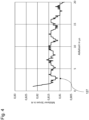
- Fig.4 shows an average recorded current value with varying fall time of the voltage profile 107.
- the voltage profiles 107 in this case have a constant waiting time of 2.3 ⁇ s and a constant rise time of 1 ⁇ s
- the repetition rate is 15 kHz and the flow rate of the hydraulic fluid is 14 ml/min.
- the fall time of the voltage profile 107 is changed between 1 ⁇ s and 20 ⁇ s (X-axis).
- a predetermined voltage profile is used here, the fall time of which is increased in small steps from the minimum value to the maximum value.
- the respective associated average current value that flows through the piezo element 103 is recorded (Y-axis).
- the sound amplitude can also be determined using a microphone.
- the voltage profile 107 is then selected with the fall time at which the average current value has a local minimum 127. This occurs at a fall time of 2.9 ⁇ s. This improves the drop shape. From this value onwards, an efficient voltage profile 107 is possible. If this fall time is not reached, the voltage profile 107 cannot function optimally because the speed of sound of the hydraulic fluid is exceeded.
- the current measurement can also be referred to as a power measurement because the voltage used is consistent and constant, such as 24 V.
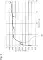
- Fig.5 shows an average recorded current value with varying waiting time of the voltage profile 107.
- the voltage profiles 107 have a constant fall time of 2.3 ⁇ s and a constant rise time of 1 ⁇ s.
- the repetition rate is 20 kHz.
- the waiting time of the voltage profile 107 is changed between 0 ⁇ s and 20 ⁇ s (X-axis).
- a predefined voltage profile 107 is used, the waiting time of which can be changed in small steps from the minimum value to the maximum value is increased.
- the corresponding average current value is recorded (Y-axis) that flows through the piezo element.
- the sound amplitude can also be determined using a microphone.
- the curve has a local minimum 127 for the average current value at a waiting time of 1.3 ⁇ s. This point depends on the relaxation speed within the pressure fluid 101.
- the local minimum 127 indicates the optimal time for the waiting time, since the least energy is used here to generate the liquid drops 115. This means that the relaxation of the pressure fluid is synchronous with the rise time.
- Fig.6 shows an average recorded current value with varying rise time of the voltage profile 107.
- the voltage profiles 107 have a constant fall time of 1 ⁇ s and a constant waiting time of 2.3 ⁇ s.
- the repetition rate is 15 kHz.
- the rise time of the voltage profile 107 is changed between 1 ⁇ s and 20 ⁇ s (X-axis).
- a predefined voltage profile 107 is used here, the rise time of which is increased in small steps from the minimum value to the maximum value.
- the respective associated average current value that flows through the piezo element is recorded (Y-axis).
- the sound amplitude can also be determined using a microphone.
- the curve has a local minimum 127 for the average current value at a rise time of 3.3 ⁇ s.
- the local minimum 127 indicates the optimal time for the rise time, since the least energy is consumed here to create the liquid drop 115. From this value onwards, an efficient voltage profile 107 is possible. If this If the rise time is exceeded, an optimal effect of the voltage profile is not possible because the speed of sound of the hydraulic fluid 101 is exceeded.
- Fig.7 shows a schematic view of a closure plate for the print head 109.
- the method can be carried out with the print nozzle 105 open or closed.
- a closure plate 111 can be used, which is attached to the print head 109.
- the relaxation time and the maximum fall and rise time can also be determined when measuring with the shutter plate closed. If a shift between the open and closed shutter plate is known, a correction value can be used to correct it.
- step S103 the piezo element 103 of the pressure nozzle 105 is controlled by the second voltage profile 107 and in step S104 an electrical current value averaged over the second voltage profile 107 or a sound amplitude averaged over the second voltage profile 107 is recorded.
- step S105 the voltage profile 107 with the lower detected current value (local minimum 127) or the lower detected sound amplitude is selected.
- the method now offers the possibility of selecting suitable voltage profiles for Ejection of the hydraulic fluid can be easily determined.
- the steps can then be repeated to find another voltage profile with an even lower recorded current value or sound amplitude. This means that a wide variety of voltage profiles 107 are generated and the optimal values recorded can be adopted automatically by the system.
- the process enables a more cost-effective optimization and time-saving of the drop shape, even when using new printing fluids. Maintenance of the printing device is made easier. Complex devices for determining the drop shape can be dispensed with, resulting in cost savings in the production of the printing device.
- This scanning and evaluation simplify the determination of an optimal voltage profile 107.
- a printer control can independently determine an optimal voltage profile 107 (autotuning) without taking a photograph of the drops (drop watching).
- the adjustment of the voltage profile 107 may be necessary if a new printing fluid 101 is used or if the print head 109 or the printing fluid is subject to aging. This autotuning enables the printer control to readjust itself independently in these cases.
- the method simplifies the setting of a drop shape. Furthermore, it is possible to determine different parameters from the printing device 100 in order to take countermeasures automatically if necessary.
- the values independently determined by the printing device 100 can be used for automatic Self-optimization or auto-tuning can be carried out by artificial intelligence in the print head control system.
- All method steps can be implemented by devices suitable for carrying out the respective method step. All functions performed by material features can be a method step of a method.
Landscapes
- Chemical & Material Sciences (AREA)
- Engineering & Computer Science (AREA)
- Materials Engineering (AREA)
- Manufacturing & Machinery (AREA)
- Physics & Mathematics (AREA)
- Mechanical Engineering (AREA)
- Optics & Photonics (AREA)
- Particle Formation And Scattering Control In Inkjet Printers (AREA)
- Ink Jet (AREA)
Abstract
Description
- Die vorliegende Erfindung betrifft ein Verfahren zum Einstellen einer Tropfenform in einem Druckprozess und eine Druckvorrichtung zum Durchführen des Verfahrens.
- Es ist die technische Aufgabe der vorliegenden Erfindung, die Tropfenform einer Druckflüssigkeit in einem Druckprozess so einzustellen, dass der Druckprozess präzise und effizient durchgeführt werden kann.
- Diese Aufgabe wird durch Gegenstände nach den unabhängigen Ansprüchen gelöst. Technisch vorteilhafte Ausführungsformen sind Gegenstand der abhängigen Ansprüche, der Beschreibung und der Zeichnungen.
- Gemäß einem ersten Aspekt wird die technische Aufgabe durch ein Verfahren zum Einstellen einer Tropfenform in einem Druckprozess gelöst, mit den Schritten eines Steuerns eines Piezoelementes einer Druckdüse durch ein erstes Spannungsprofil; eines Erfassens eines über das erste Spannungsprofil gemittelten elektrischen Stromwertes oder einer über das erste Spannungsprofil gemittelten Schallamplitude; eines Steuerns des Piezoelementes der Druckdüse durch ein zweites Spannungsprofil; eines Erfassens eines über das zweite Spannungsprofil gemittelten elektrischen Stromwertes oder einer über das zweite Spannungsprofil gemittelten Schallamplitude; und eines Auswählens desjenigen Spannungsprofils mit dem geringeren erfassten Stromwert oder der geringeren erfassten Schallamplitude. Durch das Verfahren kann eine automatische Abstimmung des Spannungsprofils für eine optimale Tropfenform erreicht werden. Ein selbstständiges Autotuning eines Druckkopfes wird ermöglicht. Auf aufwändige Geräte zur Bestimmung einer Tropfenform der ausgestoßenen Druckflüssigkeit kann verzichtet werden. Zudem verringert sich ein Zeitaufwand zur Einstellung der Tropfenform.
- In einer technisch vorteilhaften Ausführungsform des Verfahrens wird das zweite Spannungsprofil auf Basis des ersten Spannungsprofils bestimmt. Dadurch wird beispielsweise der technische Vorteil erreicht, dass das zweite Spannungsprofil auf einfache Weise erzeugt werden kann.
- In einer weiteren technisch vorteilhaften Ausführungsform des Verfahrens wird das zweite Spannungsprofil dadurch erzeugt, dass eine Anstiegszeit des ersten Spannungsprofils verkleinert oder vergrößert wird. Dadurch wird beispielsweise der technische Vorteil erreicht, dass ein lokales Minimum für den Stromwert oder die Schallamplitude gefunden werden kann, das eine geeignete Anstiegszeit angibt.
- In einer weiteren technisch vorteilhaften Ausführungsform des Verfahrens wird das zweite Spannungsprofil dadurch erzeugt, dass eine Abfallzeit des ersten Spannungsprofils verkleinert oder vergrößert wird. Dadurch wird beispielsweise der technische Vorteil erreicht, dass ein lokales Minimum für den Stromwert oder die Schallamplitude gefunden werden kann, das eine geeignete Abfallzeit angibt.
- In einer weiteren technisch vorteilhaften Ausführungsform des Verfahrens wird das zweite Spannungsprofil dadurch erzeugt, dass eine Haltezeit des ersten Spannungsprofils verkleinert oder vergrößert wird. Dadurch wird beispielsweise der technische Vorteil erreicht, dass ein lokales Minimum für den Stromwert oder die Schallamplitude gefunden werden kann, das eine geeignete Haltezeit angibt.
- In einer weiteren technisch vorteilhaften Ausführungsform des Verfahrens wird das zweite Spannungsprofil dadurch erzeugt, dass eine Haltespannung des ersten Spannungsprofils verkleinert oder vergrößert wird. Dadurch wird beispielsweise der technische Vorteil erreicht, dass ein lokales Minimum für den Stromwert oder die Schallamplitude gefunden werden kann, das eine geeignete Haltespannung angibt.
- In einer weiteren technisch vorteilhaften Ausführungsform des Verfahrens wird das zweite Spannungsprofil dadurch erzeugt, dass eine Haltespannung des ersten Spannungsprofils unverändert bleibt. Dadurch wird beispielsweise der technische Vorteil erreicht, dass sich der Parameterraum für das Spannungsprofil verkleinert und dieses mit geringerem Aufwand ermittelt werden kann.
- In einer weiteren technisch vorteilhaften Ausführungsform des Verfahrens wird das zweite Spannungsprofil dadurch erzeugt, dass eine Haltezeit des ersten Spannungsprofils unverändert bleibt. Dadurch wird beispielsweise ebenfalls der technische Vorteil erreicht, dass sich der Parameterraum für das Spannungsprofil verkleinert und dieses mit geringerem Aufwand ermittelt werden kann.
- In einer weiteren technisch vorteilhaften Ausführungsform des Verfahrens ist das erste Spannungsprofil ein vorgegebenes Spannungsprofil. Dadurch wird beispielsweise der technische Vorteil erreicht, dass das Verfahren von einem vorab festgelegten und besonders geeigneten Spannungsprofil begonnen werden kann.
- In einer weiteren technisch vorteilhaften Ausführungsform des Verfahrens wird eine Vielzahl von vorgegebenen Spannungsprofilen gespeichert. Dadurch wird beispielsweise der technische Vorteil erreicht, dass für unterschiedliche Druckflüssigkeiten unterschiedliche Spannungsprofile verwendet werden können.
- In einer weiteren technisch vorteilhaften Ausführungsform des Verfahrens wird das erste und/oder zweite Spannungsprofil aus der Vielzahl von vorgegebenen Spannungsprofilen ausgewählt. Dadurch wird beispielsweise der technische Vorteil erreicht, dass die Auswahl eines Spannungsprofils je nach Druckflüssigkeit erfolgen kann. Durch die Verwendung von geeigneten Spannungsprofilen je nach Druckflüssigkeit kann das Verfahren schneller konvergieren und durchgeführt werden.
- In einer weiteren technisch vorteilhaften Ausführungsform des Verfahrens wird das Verfahren durchgeführt, wenn die Druckflüssigkeit im Druckkopf oder Drucksystem gewechselt wird oder wenn eine vorgegebene Zeit abgelaufen ist. Dadurch wird beispielsweise der technische Vorteil erreicht, dass bei einem Wechsel der Druckflüssigkeit automatisch ein geeignetes Spannungsprofil zum Einstellen der Flüssigkeitstropfen erhalten wird oder eine Alterung des Druckkopfes und dessen Komponenten kompensiert werden kann. Zudem können die Spannungsprofile an die rheologischen Veränderungen der Druckflüssigkeit angepasst werden, wie beispielsweise bei Temperaturschwankungen der Umgebung oder einer Erhitzung der Anlage während dem Betrieb.
- In einer weiteren technisch vorteilhaften Ausführungsform des Verfahrens ist das Verfahren ein dreidimensionales Druckverfahren zum Aufbauen eines räumlichen Objektes. Dadurch wird beispielsweise der technische Vorteil erreicht, dass besonders geeignete Spannungsprofile für Druckflüssigkeiten erhalten werden, die zum schichtweisen Aufbauen des räumlichen Objektes verwendet werden.
- In einer weiteren technisch vorteilhaften Ausführungsform des Verfahrens wird der Druckkopf durch eine Verschlussplatte abgedeckt. Dadurch wird beispielsweise der technische Vorteil erreicht, dass keine Druckflüssigkeit während des Verfahrens verschwendet wird.
- Gemäß einem zweiten Aspekt wird die technische Aufgabe durch eine Druckvorrichtung gelöst, die ausgebildet ist, das Verfahren nach dem ersten Aspekt auszuführen. Durch die Druckvorrichtung werden die gleichen technischen Vorteile wie durch das Verfahren nach dem ersten Aspekt erreicht.
- Ausführungsbeispiele der Erfindung sind in den Zeichnungen dargestellt und werden im Folgenden näher beschrieben.
- Es zeigen:
- Fig. 1
- eine schematische Querschnittsansicht eines Druckkopfes;
- Fig. 2
- eine schematische Ansicht unterschiedlicher Tropfen einer Druckflüssigkeit;
- Fig. 3
- eine schematische Ansicht eines Spannungsprofils zum Ansteuern eines Piezoelements;
- Fig. 4
- einen mittleren erfassten Stromwert bei variierender Abfallzeit;
- Fig. 5
- einen mittleren erfassten Stromwert bei variierender Wartezeit;
- Fig. 6
- einen mittleren erfassten Stromwert bei variierender Anstiegszeit;
- Fig. 7
- eine schematische Ansicht einer Verschlussplatte für einen Druckkopf; und
- Fig. 8
- ein Blockdiagramm eines Verfahrens zum Einstellen einer Tropfenform.
-
Fig. 1 zeigt eine schematische Querschnittsansicht eines steuerbaren Druckkopfes 109 einer Druckvorrichtung 100. Die Druckvorrichtung 100 verwendet einen Strahl von Flüssigkeitstropfen 115 für einen Druckprozess (Inkjet-Verfahren). Der Druckprozess kann ein zweidimensionaler Druckprozess zum Erzeugen von Bildern durch das Aufbringen von Tinte sein oder ein dreidimensionaler Druckprozess zum Erzeugen von räumlichen Objekten 113, die durch eine Druckflüssigkeit 101 erzeugt werden, die schichtweise auf einer Bauplattform 119 akkumuliert. - Für das Ausstoßen der Druckflüssigkeit 101 ist in dem Druckkopf 109 der Druckvorrichtung 100 zumindest ein Piezoelement 103 verbaut, das einen elektrischen Spannungsimpuls in eine Bewegung umsetzt und auf die Druckflüssigkeit 101 in der Tintenkammer 117 überträgt. Die Bewegung des Piezoelements 103 wird durch den inversen piezoelektrischen Effekt erreicht, der bewirkt, dass das Piezoelement 103 bei einer negativen Spannung eine Abwärtsbewegung (Fall) und bei einer positiven Spannung eine Aufwärtsbewegung (Rise) erzeugt.
- Zum Ansteuern der Piezoelemente 103 wird ein Spannungsprofil verwendet, das verschiedene Abschnitte aufweist. Je nach Spannungsprofil und verwendeter Druckflüssigkeit 101 entstehen unterschiedlich ausgebildete Flüssigkeitstropfen 115.
-
Fig. 2 zeigt eine schematische Ansicht unterschiedlicher Flüssigkeitstropfen 115 der Druckflüssigkeit 101. Durch das verwendete Spannungsprofil 107 sollten homogene Flüssigkeitstropfen 115 erzeugt werden, ohne dass langgezogene Tropfen, Sprüheffekte oder Satellitentropfen entstehen. Satellitentropfen sind kleine Flüssigkeitstropfen 115 neben dem Haupttropfen (Doppeltropfen), die sich chaotisch ablagern und das Druckbild verschlechtern. Eine Kontamination der Druckflüssigkeit in das Druckbild oder Aufbaumaterial der anderen sollte vermieden werden. - Idealerweise wird durch das verwendete Spannungsprofil 107 ein einziger kugelförmiger Flüssigkeitstropfen 115 erzeugt, der sich mit einer vorgegebenen Geschwindigkeit bewegt, wie beispielsweise 4 bis 9 m/s. Um dies zu erreichen, wird das Spannungsprofil 107 entsprechend angepasst (Wave Tuning).
-
Fig. 3 zeigt eine schematische Ansicht eines trapezförmigen Spannungsprofils 107 zum Ansteuern des Piezoelements 103. Das Spannungsprofil 107 wird durch eine elektronische Steuereinheit mit einer elektrischen Schaltung erzeugt und kann als vorab vorgegebenes Spannungsprofil 107 in der Druckvorrichtung 100 abgelegt sein. Hierzu können die Daten des Spannungsprofils 107 digital in der Steuereinheit gespeichert werden. Die Steuereinheit kann auch eine Vielzahl von vorgegebenen Spannungsprofilen 107 speichern, von denen eines je nach verwendeter Druckflüssigkeit als Startpunkt für das Verfahren ausgewählt wird. - Das Spannungsprofil 107 umfasst drei Abschnitte, nämlich einen ersten Startabschnitt 121 mit einer Abfallzeit, in dem die elektrische Spannung ansteigt, einen zweiten Halteabschnitt 123 mit einer Wartezeit, in dem die elektrische Spannung konstant ist, und einen dritten Endabschnitt 125 mit einer Anstiegszeit, in dem die elektrische Spannung abfällt. Um eine geeignete Tropfenform zu erzeugen, werden die jeweiligen Abschnitte 121, 123 und 125 verändert.
- Dabei werden die Abfallzeit (Fall Time), Wartezeit (Waiting Time) und Anstiegszeit (Rise Time) der jeweiligen Abschnitte 121, 123 und 125 verändert und angepasst. Da sich jede Druckflüssigkeit 101 rheologisch unterscheidet, sollte für jede Druckflüssigkeit 101 jeweils ein entsprechend angepasstes Spannungsprofil 107 für den Druckprozess verwendet werden.
- Die Abfallzeit (Fall Time) erzeugt eine Ziehbewegung (Pull) des Piezoelementes 103. Der Startabschnitt 121 setzt sich aus der Abfallzeit und einer Abfallspannung zusammen. Die Abfallspannung hat beispielsweise einen Einfluss auf die erzeugte Tropfengröße. Bei einer starken Veränderung der Abfallspannung sollte die Schallgeschwindigkeit der Druckflüssigkeit 101 nicht überschritten werden.
- Die Wartezeit (Waiting Time) ist die Zeit bei einer konstanten Spannung im Halteabschnitt 123, in der die Druckflüssigkeit 101 relaxiert. Die Relaxation hängt mit der Schallgeschwindigkeit innerhalb der Druckflüssigkeit 101 zusammen. Das Ende der Wartezeit sollte möglichst genau mit der Relaxation der Druckflüssigkeit 101 in der Tintenkammer 117 des Druckkopfes 109 übereinstimmen, so dass zu diesem Zeitpunkt die Anstiegszeit synchron mit der Relaxationsbewegung beginnt.
- Die Anstiegszeit (Rise Time) im Endabschnitt 125 erzeugt eine Stoßbewegung (Push) des Piezoelements 103. Die von der Abfallzeit erzeugte Bewegung der Druckflüssigkeit 101 und die in der Wartezeit entstehende Relaxation der Druckflüssigkeit 101 wird während der Anstiegszeit zusätzlich beschleunigt, so dass ein Flüssigkeitstropfen 115 aus der Tintenkammer 117 durch die Druckdüse 105 entweicht.
- Die Amplitudenhöhe ist die Höhe der elektrischen Spannung während der Wartezeit und korreliert mit der Größe des ausgestoßenen Flüssigkeitstropfens 115. Bei einem Abstimmen des Spannungsprofils 107 kann eine konstante vorgegebene Spannung als Amplitudenhöhe verwendet werden.
- Bei einem Abstimmen des Spannungsprofils 107 (Wave Tuning) werden unterschiedliche Spannungsprofile 107 mit unterschiedlicher Abfallzeit, Wartezeit, Anstiegszeit und Amplitudenhöhe erzeugt. Danach wird für die einzelnen Spannungsprofile 107 der elektrische Strom durch das Piezoelement 103 mit einem Amperemeter oder einer geeigneten elektrischen Schaltung bestimmt und über die Dauer des Spannungsprofils 107 gemittelt, beispielsweise durch Integrieren einzelner Stromwerte über die Zeit. Das Spannungsprofil 107 kann wiederholt mit einer Wiederholfrequenz auf das Piezoelement 103 angewendet werden, um während dieser Dauer den elektrischen Strom durch das Piezoelement 103 zu mitteln.
- Statt dem elektrischen Strom durch das Piezoelement 103 kann auch die Schallamplitude verwendet werden, die durch das Piezoelement 103 erzeugt wird. Die so erfassten Werte für den elektrischen Strom oder die Schallamplitude werden anschließend für eine Auswahl eines der erzeugten Spannungsprofile 107 verwendet.
-
Fig. 4 zeigt einen mittleren erfassten Stromwert bei variierender Abfallzeit des Spannungsprofils 107. Die Spannungsprofile 107 weisen in diesem Fall eine konstante Wartezeit von 2.3 µs und eine konstante Anstiegszeit von 1 µs auf. Die Wiederholrate beträgt 15 kHz und der Durchfluss der Druckflüssigkeit 14 ml/min. - Die Abfallzeit des Spannungsprofils 107 wird hingegen zwischen 1 µs und 20 µs verändert (X-Achse). Hierbei wird ein vorgegebenes Spannungsprofil verwendet, dessen Abfallzeit von dem Minimalwert in kleinen Schritten bis zu dem Maximalwert erhöht wird. Zu jeder Abfallzeit wird der jeweilige zugehörige mittlere Stromwert erfasst (Y-Achse), der durch das Piezoelement 103 fließt. Alternativ kann auch die Schallamplitude mit einem Mikrofon ermittelt werden.
- Anschließend wird das Spannungsprofil 107 mit derjenigen Abfallzeit ausgewählt, bei dem der mittlere Stromwert ein lokales Minimum 127 aufweist. Dieses tritt bei einer Abfallzeit von 2.9 µs auf. Dadurch verbessert sich die Tropfenform. Ab diesem Wert ist ein effizientes Spannungsprofil 107 möglich. Wenn diese Abfallzeit unterschritten wird, ist ein optimales Wirken des Spannungsprofils 107 nicht möglich, da die Schallgeschwindigkeit der Druckflüssigkeit überschritten wird. Die Strommessung kann auch als Leistungsmessung bezeichnet werden, weil die verwendete Spannung gleichbleibend und konstant ist, wie beispielsweise 24 V.
-
Fig. 5 zeigt einen mittleren erfassten Stromwert bei variierender Wartezeit des Spannungsprofils 107. Die Spannungsprofile 107 weisen eine konstante Abfallzeit von 2.3 µs und konstante Anstiegszeit von 1 µs auf. Die Wiederholrate beträgt 20 kHz. - Die Wartezeit des Spannungsprofils 107 wird hingegen zwischen 0 µs und 20 µs verändert (X-Achse). Hierbei wird ein vorgegebenes Spannungsprofil 107 verwendet, dessen Wartezeit von dem Minimalwert in kleinen Schritten bis zu dem Maximalwert erhöht wird. Zu jeder Wartezeit wird der jeweilige zugehörige mittlere Stromwert erfasst (Y-Achse), der durch das Piezoelement fließt. Alternativ kann auch die Schallamplitude mit einem Mikrofon ermittelt werden.
- Die Kurve weist bei einer Wartezeit von 1.3 µs ein lokales Minimum 127 für den mittleren Stromwert auf. Dieser Punkt hängt von der Relaxationsgeschwindigkeit innerhalb der Druckflüssigkeit 101 ab. Das lokale Minimum 127 gibt die optimale Zeit für die Wartezeit an, da hier am wenigsten Energie für die Erzeugung der Flüssigkeitstropfen 115 verbraucht wird. Dies bedeutet, dass die Relaxation der Druckflüssigkeit synchron mit der Anstiegszeit verläuft.
-
Fig. 6 zeigt einen mittleren erfassten Stromwert bei variierender Anstiegszeit des Spannungsprofils 107. Die Spannungsprofile 107 weisen eine konstante Abfallzeit von 1 µs und konstante Wartezeit von 2.3 µs auf. Die Wiederholrate beträgt 15 kHz. - Die Anstiegszeit des Spannungsprofils 107 wird hingegen zwischen 1 µs und 20 µs verändert (X-Achse). Hierbei wird ein vorgegebenes Spannungsprofil 107 verwendet, dessen Anstiegszeit von dem Minimalwert in kleinen Schritten bis zu dem Maximalwert erhöht wird. Zu jeder Anstiegszeit wird der jeweilige zugehörige mittlere Stromwert erfasst (Y-Achse), der durch das Piezoelement fließt. Alternativ kann auch die Schallamplitude mit einem Mikrofon ermittelt werden.
- Die Kurve weist bei einer Anstiegszeit von 3.3 µs ein lokales Minimum 127 für den mittleren Stromwert auf. Das lokale Minimum 127 gibt die optimale Zeit für die Anstiegszeit an, da hier am wenigsten Energie für die Erzeugung des Flüssigkeitstropfens 115 verbraucht wird. Ab diesem Wert ist ein effizientes Spannungsprofil 107 möglich. Wenn diese Anstiegszeit unterschritten wird, ist ein optimales Wirken des Spannungsprofils nicht möglich, da die Schallgeschwindigkeit der Druckflüssigkeit 101 überschritten wird.
-
Fig. 7 zeigt eine schematische Ansicht einer Verschlussplatte für den Druckkopf 109. Das Verfahren kann mit geöffneter oder verschlossener Druckdüse 105 durchgeführt werden. Zum Verschließen der Druckdüse 105 kann eine Verschlussplatte 111 verwendet werden, die an dem Druckkopf 109 befestigt wird. - Auch beim Messen mit geschlossener Verschlussplatte kann die Relaxationszeit und die maximale Abfall- und Anstiegszeit ermittelt werden. Wenn eine Verschiebung zwischen offener und geschlossener Verschlussplatte bekannt ist, kann mit einem Korrekturwert korrigiert werden.
-
Fig. 8 zeigt ein Blockdiagramm eines Verfahrens zum Einstellen einer Tropfenform einer Druckflüssigkeit. Das Verfahren umfasst die Schritte S101 eines Steuerns des Piezoelementes 103 der Druckdüse 105 durch das erste Spannungsprofil 107 und den Schritt S102 des Erfassens des über das erste Spannungsprofil 107 gemittelten elektrischen Stromwertes oder der über das erste Spannungsprofil 107 gemittelten Schallamplitude. - Anschließend wird in Schritt S103 das Piezoelement 103 der Druckdüse 105 durch das zweite Spannungsprofil 107 gesteuert und in Schritt S104 ein über das zweite Spannungsprofil 107 gemittelter elektrischer Stromwert oder eine über das zweite Spannungsprofil 107 gemittelte Schallamplitude erfasst.
- In Schritt S105 wird dasjenige Spannungsprofil 107 mit dem geringeren erfassten Stromwert (lokales Minimum 127) oder der geringeren erfassten Schallamplitude ausgewählt. Das Verfahren bietet nun die Möglichkeit, geeignete Spannungsprofile zum Ausstoßen der Druckflüssigkeit auf einfache Weise zu ermitteln.
- Anschließend können die Schritte wiederholt werden, um ein weiteres Spannungsprofil mit einem noch geringeren erfassten Stromwert oder Schallamplitude zu finden. Dies bedeutet, dass verschiedenste Spannungsprofile 107 erzeugt werden und die dabei aufgezeichneten optimalen Werte vom System selbstständig übernommen werden können.
- Durch das Verfahren kann eine kostengünstigere Optimierung und Zeitersparnis der Tropfenform auch bei der Verwendung neuer Druckflüssigkeiten erfolgen. Eine Wartung der Druckvorrichtung wird erleichtert. Auf aufwändige Vorrichtungen zur Ermittlung der Tropfenform kann verzichtet werden, so dass sich eine Kostenersparnis bei der Herstellung der Druckvorrichtung ergibt.
- Dieses Scannen und Auswerten vereinfachen das Ermitteln eines optimalen Spannungsprofils 107. So kann beispielsweise eine Druckersteuerung selbstständig, ohne eine fotografische Aufnahme der Tropfen (Drop Watching), ein optimales Spannungsprofil 107 ermitteln (Autotuning). Die Anpassung des Spannungsprofils 107 kann erforderlich sein, wenn eine neue Druckflüssigkeit 101 verwendet wird oder der Druckkopf 109 oder die Druckflüssigkeit einer Alterung unterliegt. Dieses Autotuning ermöglicht es der Druckersteuerung, sich selbstständig in diesen Fällen nachzujustieren.
- Durch das Verfahren wird eine Vereinfachung eines Einstellens einer Tropfenform erreicht. Des Weiteren ist es möglich, unterschiedliche Parameter aus der Druckvorrichtung 100 zu eruieren, um gegebenenfalls automatisiert Gegenmaßnahmen zu ergreifen. Die von der Druckvorrichtung 100 selbstständig ermittelten Werte können für eine automatische Selbstoptimierung oder ein Autotuning durch eine künstliche Intelligenz von der Druckkopfsteuerung übernommen werden.
- Alle in Verbindung mit einzelnen Ausführungsformen der Erfindung erläuterten und gezeigten Merkmale können in unterschiedlicher Kombination in dem erfindungsgemäßen Gegenstand vorgesehen sein, um gleichzeitig deren vorteilhafte Wirkungen zu realisieren.
- Alle Verfahrensschritte können durch Vorrichtungen implementiert werden, die zum Ausführen des jeweiligen Verfahrensschrittes geeignet sind. Alle Funktionen, die von gegenständlichen Merkmalen ausgeführt werden, können ein Verfahrensschritt eines Verfahrens sein.
- Der Schutzbereich der vorliegenden Erfindung ist durch die Ansprüche gegeben und wird durch die in der Beschreibung erläuterten oder den Figuren gezeigten Merkmale nicht beschränkt.
-
- 100
- Druckvorrichtung
- 101
- Druckflüssigkeit
- 103
- Piezoelement
- 105
- Druckdüse
- 107
- Spannungsprofil
- 109
- Druckkopf
- 111
- Verschlussplatte
- 113
- räumliches Objekt
- 115
- Flüssigkeitstropfen
- 117
- Tintenkammer
- 119
- Bauplattform
- 121
- Startabschnitt
- 123
- Halteabschnitt
- 125
- Endabschnitt
- 127
- lokales Minimum
Claims (15)
- Verfahren zum Einstellen einer Tropfenform in einem Druckprozess, mit den Schritten:- Steuern (S101) eines Piezoelementes (103) einer Druckdüse (105) durch ein erstes Spannungsprofil (107);- Erfassen (S102) eines über das erste Spannungsprofil (107) gemittelten elektrischen Stromwertes oder einer über das erste Spannungsprofil (107) gemittelten Schallamplitude;- Steuern (S103) des Piezoelementes (103) der Druckdüse (105) durch ein zweites Spannungsprofil (107);- Erfassen (S104) eines über das zweite Spannungsprofil (107) gemittelten elektrischen Stromwertes oder einer über das zweite Spannungsprofil (107) gemittelten Schallamplitude; und- Auswählen (S105) desjenigen Spannungsprofils (107, 107) mit dem geringeren erfassten Stromwert oder der geringeren erfassten Schallamplitude.
- Verfahren nach Anspruch 1, wobei das zweite Spannungsprofil (107) auf Basis des ersten Spannungsprofils (107) bestimmt wird.
- Verfahren nach einem der vorangehenden Ansprüche, wobei das zweite Spannungsprofil (107) dadurch erzeugt wird, dass eine Anstiegszeit des ersten Spannungsprofils (107) verkleinert oder vergrößert wird.
- Verfahren nach einem der vorangehenden Ansprüche, wobei das zweite Spannungsprofil (107) dadurch erzeugt wird, dass eine Abfallzeit des ersten Spannungsprofils (107) verkleinert oder vergrößert wird.
- Verfahren nach einem der vorangehenden Ansprüche, wobei das zweite Spannungsprofil (107) dadurch erzeugt wird, dass eine Haltezeit des ersten Spannungsprofils (107) verkleinert oder vergrößert wird.
- Verfahren nach einem der vorangehenden Ansprüche, wobei das zweite Spannungsprofil (107) dadurch erzeugt wird, dass eine Haltespannung des ersten Spannungsprofils (107) verkleinert oder vergrößert wird.
- Verfahren nach einem der vorangehenden Ansprüche, wobei das zweite Spannungsprofil (107) dadurch erzeugt wird, dass eine Haltespannung des ersten Spannungsprofils (107) unverändert bleibt.
- Verfahren nach einem der vorangehenden Ansprüche, wobei das zweite Spannungsprofil (107) dadurch erzeugt wird, dass eine Haltezeit des ersten Spannungsprofils (107) unverändert bleibt.
- Verfahren nach einem der vorangehenden Ansprüche, wobei das erste Spannungsprofil (107) ein vorgegebenes Spannungsprofil ist.
- Verfahren nach einem der vorangehenden Ansprüche, wobei eine Vielzahl von vorgegebenen Spannungsprofilen (107) gespeichert wird.
- Verfahren nach Anspruch 10, wobei das erste und/oder zweite Spannungsprofil aus der Vielzahl von vorgegebenen Spannungsprofilen ausgewählt wird.
- Verfahren nach einem der vorangehenden Ansprüche, wobei das Verfahren durchgeführt wird, wenn die Druckflüssigkeit im Druckkopf (109) oder Drucksystem gewechselt wird oder wenn eine vorgegebene Zeit abgelaufen ist.
- Verfahren nach einem der vorangehenden Ansprüche, wobei das Verfahren ein dreidimensionales Druckverfahren zum Aufbauen eines räumlichen Objektes (113) ist.
- Verfahren nach einem der vorangehenden Ansprüche, wobei der Druckkopf (109) durch eine Verschlussplatte (111) abgedeckt wird.
- Druckvorrichtung (100), die ausgebildet ist, das Verfahren nach einem der Ansprüche 1 bis 14 auszuführen.
Priority Applications (7)
| Application Number | Priority Date | Filing Date | Title |
|---|---|---|---|
| ES23161781T ES3056515T3 (en) | 2023-03-14 | 2023-03-14 | Method for adjusting a drop shape in a printing process |
| EP23161781.2A EP4431287B1 (de) | 2023-03-14 | 2023-03-14 | Verfahren zum einstellen einer tropfenform in einem druckprozess |
| CA3228999A CA3228999A1 (en) | 2023-03-14 | 2024-02-13 | Method for setting a drop shape in a printing process |
| CN202410207718.1A CN118650985A (zh) | 2023-03-14 | 2024-02-26 | 用于在打印过程中设置液滴形状的方法和打印装置 |
| US18/599,121 US12544985B2 (en) | 2023-03-14 | 2024-03-07 | Method for setting a drop shape in a printing process |
| JP2024036367A JP2024132959A (ja) | 2023-03-14 | 2024-03-08 | 印刷プロセス中の滴形状を制御する方法 |
| KR1020240034449A KR20240139564A (ko) | 2023-03-14 | 2024-03-12 | 인쇄 공정에서의 액적형상 설정 방법 |
Applications Claiming Priority (1)
| Application Number | Priority Date | Filing Date | Title |
|---|---|---|---|
| EP23161781.2A EP4431287B1 (de) | 2023-03-14 | 2023-03-14 | Verfahren zum einstellen einer tropfenform in einem druckprozess |
Publications (2)
| Publication Number | Publication Date |
|---|---|
| EP4431287A1 true EP4431287A1 (de) | 2024-09-18 |
| EP4431287B1 EP4431287B1 (de) | 2025-11-26 |
Family
ID=85640718
Family Applications (1)
| Application Number | Title | Priority Date | Filing Date |
|---|---|---|---|
| EP23161781.2A Active EP4431287B1 (de) | 2023-03-14 | 2023-03-14 | Verfahren zum einstellen einer tropfenform in einem druckprozess |
Country Status (7)
| Country | Link |
|---|---|
| US (1) | US12544985B2 (de) |
| EP (1) | EP4431287B1 (de) |
| JP (1) | JP2024132959A (de) |
| KR (1) | KR20240139564A (de) |
| CN (1) | CN118650985A (de) |
| CA (1) | CA3228999A1 (de) |
| ES (1) | ES3056515T3 (de) |
Citations (4)
| Publication number | Priority date | Publication date | Assignee | Title |
|---|---|---|---|---|
| US5646654A (en) * | 1995-03-09 | 1997-07-08 | Hewlett-Packard Company | Ink-jet printing system having acoustic transducer for determining optimum operating energy |
| US20010028371A1 (en) * | 1996-07-24 | 2001-10-11 | Wen-Li Su | Acoustic and ultrasonic monitoring of inkjet droplets |
| US20040017412A1 (en) * | 2002-07-05 | 2004-01-29 | Groninger Mark Alexander | Inkjet printhead, a method of controlling an inkjet printhead, and an inkjet printer provided with such a printhead |
| US20130321507A1 (en) * | 2011-04-28 | 2013-12-05 | Peter Mardilovich | Compensating for capacitance changes in piezoelectric printhead elements |
Family Cites Families (6)
| Publication number | Priority date | Publication date | Assignee | Title |
|---|---|---|---|---|
| JP2012236299A (ja) | 2011-05-11 | 2012-12-06 | Seiko Epson Corp | 流体吐出装置、ノズル検査方法、及び、ノズル検査プログラム |
| JP5560253B2 (ja) * | 2011-09-30 | 2014-07-23 | 富士フイルム株式会社 | インクジェット記録装置及び方法並びに異常ノズル検知方法 |
| JP5723804B2 (ja) | 2012-02-21 | 2015-05-27 | 東芝テック株式会社 | インクジェットヘッドおよびインクジェット記録装置 |
| EP3274177B1 (de) | 2015-03-24 | 2019-05-08 | OCE-Technologies B.V. | Strahlvorrichtung mit filterzustandsdetektion |
| US10703097B2 (en) * | 2017-06-22 | 2020-07-07 | Konica Minolta, Inc. | Inkjet recorder and method of detecting malfunction |
| JP7322947B2 (ja) * | 2019-03-29 | 2023-08-08 | コニカミノルタ株式会社 | インクジェットヘッドの駆動方法及びインクジェット記録装置 |
-
2023
- 2023-03-14 EP EP23161781.2A patent/EP4431287B1/de active Active
- 2023-03-14 ES ES23161781T patent/ES3056515T3/es active Active
-
2024
- 2024-02-13 CA CA3228999A patent/CA3228999A1/en active Pending
- 2024-02-26 CN CN202410207718.1A patent/CN118650985A/zh active Pending
- 2024-03-07 US US18/599,121 patent/US12544985B2/en active Active
- 2024-03-08 JP JP2024036367A patent/JP2024132959A/ja active Pending
- 2024-03-12 KR KR1020240034449A patent/KR20240139564A/ko active Pending
Patent Citations (4)
| Publication number | Priority date | Publication date | Assignee | Title |
|---|---|---|---|---|
| US5646654A (en) * | 1995-03-09 | 1997-07-08 | Hewlett-Packard Company | Ink-jet printing system having acoustic transducer for determining optimum operating energy |
| US20010028371A1 (en) * | 1996-07-24 | 2001-10-11 | Wen-Li Su | Acoustic and ultrasonic monitoring of inkjet droplets |
| US20040017412A1 (en) * | 2002-07-05 | 2004-01-29 | Groninger Mark Alexander | Inkjet printhead, a method of controlling an inkjet printhead, and an inkjet printer provided with such a printhead |
| US20130321507A1 (en) * | 2011-04-28 | 2013-12-05 | Peter Mardilovich | Compensating for capacitance changes in piezoelectric printhead elements |
Also Published As
| Publication number | Publication date |
|---|---|
| CN118650985A (zh) | 2024-09-17 |
| US12544985B2 (en) | 2026-02-10 |
| US20240308143A1 (en) | 2024-09-19 |
| JP2024132959A (ja) | 2024-10-01 |
| KR20240139564A (ko) | 2024-09-23 |
| ES3056515T3 (en) | 2026-02-23 |
| CA3228999A1 (en) | 2025-07-08 |
| EP4431287B1 (de) | 2025-11-26 |
Similar Documents
| Publication | Publication Date | Title |
|---|---|---|
| DE2348724C3 (de) | Vorrichtung zum Synchronisieren der Tröpfchenbildung mit der Tröpfchenaufladung in einem Tintenstrahldrucker | |
| DE2623768C2 (de) | Verfahren und Vorrichtung zur Wiedergabe von Halbtonbildern | |
| DE2943164C2 (de) | ||
| DE69212564T2 (de) | Gerät und Verfahren zum Antreiben eines Tintenstrahlaufzeichnungskopfes | |
| DE69603899T2 (de) | Antriebsvorrichtung zur Erzeugung eines Strahles von Tintentröpfchen | |
| DE2425679C3 (de) | Vorrichtung zum Erzeugen und selektiven Ablenken von Flüssigkeitströpfchen | |
| DE3327904C2 (de) | Thermoaufzeichnungsgerät | |
| EP1036660A1 (de) | Piezobiegewandler Drop-on-Demand Druckkopf sowie Verfahren zu dessen Ansteuerung | |
| EP3199347B1 (de) | Anpassung der tropfengrösse zur dichtekompensation | |
| DE2457327B2 (de) | Phasensynchronisierer fur einen Tintenstrahlschreiber | |
| DE69505960T2 (de) | Verbesserungen an einer gepulsten tröpfchen-niederschlagsvorrichtung | |
| DE3513442C2 (de) | Verfahren zum Betreiben eines Tintenstrahldruckers | |
| DE4428807C2 (de) | Vorrichtung zur Geschwindigkeits- und Tropfenmassenvariation bei thermischen Tintenschreibern | |
| DE2541082B2 (de) | Vorrichtung zum Synchronisieren von Tröpfchenbildung und -aufladung bei einem Tintenstrahlschreiber | |
| DE69724527T2 (de) | Verfahren zur Regelung der Menge von aus einer Mehrzahl von Flüssigkeitsausstossdüseeinheiten ausgestossener Flüssigkeit, Tintenstrahlsteuerverfahren unter Anwendung dieses Regelverfahrens und Tintenstrahlapparat | |
| DE69730380T2 (de) | Druckverfahren und Drucksystem | |
| DE69938385T2 (de) | Antriebsvorrichtung und Antriebsverfahren eines auf Abruf arbeitenden Tintenstrahldruckkopfes | |
| DE102015116656A1 (de) | Verfahren zum Reduzieren einer lokal erhöhten Viskosität von Tinte in einem Tintendruckkopf eines Tintendruckers während des Druckbetriebs | |
| EP4431287B1 (de) | Verfahren zum einstellen einer tropfenform in einem druckprozess | |
| DE69713811T2 (de) | Steuerung für eine kontinuierlich arbeitende tintenstrahldruckersteuerung | |
| DE60119207T2 (de) | Kontinuierlich arbeitender Tintenstrahldrucker mit asymmetrischer Tropfenumlenkung | |
| DE2554368A1 (de) | Tintenstrahldrucker und verfahren zu dessen betrieb | |
| DE3839089C2 (de) | Halbton-Drucksystem | |
| DE2560392C2 (de) | Einrichtung zur Aufteilung von aus in einer Reihe angeordneten Düsen ausgestoßenen Tintenströmen in einzelne Tropfen | |
| DE69713905T2 (de) | Kontinuierlicher tintenstrahldruck |
Legal Events
| Date | Code | Title | Description |
|---|---|---|---|
| PUAI | Public reference made under article 153(3) epc to a published international application that has entered the european phase |
Free format text: ORIGINAL CODE: 0009012 |
|
| STAA | Information on the status of an ep patent application or granted ep patent |
Free format text: STATUS: THE APPLICATION HAS BEEN PUBLISHED |
|
| AK | Designated contracting states |
Kind code of ref document: A1 Designated state(s): AL AT BE BG CH CY CZ DE DK EE ES FI FR GB GR HR HU IE IS IT LI LT LU LV MC ME MK MT NL NO PL PT RO RS SE SI SK SM TR |
|
| STAA | Information on the status of an ep patent application or granted ep patent |
Free format text: STATUS: REQUEST FOR EXAMINATION WAS MADE |
|
| 17P | Request for examination filed |
Effective date: 20250121 |
|
| GRAP | Despatch of communication of intention to grant a patent |
Free format text: ORIGINAL CODE: EPIDOSNIGR1 |
|
| STAA | Information on the status of an ep patent application or granted ep patent |
Free format text: STATUS: GRANT OF PATENT IS INTENDED |
|
| INTG | Intention to grant announced |
Effective date: 20250717 |
|
| GRAS | Grant fee paid |
Free format text: ORIGINAL CODE: EPIDOSNIGR3 |
|
| P01 | Opt-out of the competence of the unified patent court (upc) registered |
Free format text: CASE NUMBER: UPC_APP_7250_4431287/2025 Effective date: 20250916 |
|
| GRAA | (expected) grant |
Free format text: ORIGINAL CODE: 0009210 |
|
| STAA | Information on the status of an ep patent application or granted ep patent |
Free format text: STATUS: THE PATENT HAS BEEN GRANTED |
|
| AK | Designated contracting states |
Kind code of ref document: B1 Designated state(s): AL AT BE BG CH CY CZ DE DK EE ES FI FR GB GR HR HU IE IS IT LI LT LU LV MC ME MK MT NL NO PL PT RO RS SE SI SK SM TR |
|
| REG | Reference to a national code |
Ref country code: CH Ref legal event code: F10 Free format text: ST27 STATUS EVENT CODE: U-0-0-F10-F00 (AS PROVIDED BY THE NATIONAL OFFICE) Effective date: 20251126 Ref country code: GB Ref legal event code: FG4D Free format text: NOT ENGLISH |
|
| REG | Reference to a national code |
Ref country code: CH Ref legal event code: R17 Free format text: ST27 STATUS EVENT CODE: U-0-0-R10-R17 (AS PROVIDED BY THE NATIONAL OFFICE) Effective date: 20251127 |
|
| REG | Reference to a national code |
Ref country code: IE Ref legal event code: FG4D Free format text: LANGUAGE OF EP DOCUMENT: GERMAN |
|
| REG | Reference to a national code |
Ref country code: DE Ref legal event code: R096 Ref document number: 502023002291 Country of ref document: DE |
|
| REG | Reference to a national code |
Ref country code: NL Ref legal event code: FP |
|
| REG | Reference to a national code |
Ref country code: ES Ref legal event code: FG2A Ref document number: 3056515 Country of ref document: ES Kind code of ref document: T3 Effective date: 20260223 |
|
| REG | Reference to a national code |
Ref country code: LT Ref legal event code: MG9D |
|
| PG25 | Lapsed in a contracting state [announced via postgrant information from national office to epo] |
Ref country code: NO Free format text: LAPSE BECAUSE OF FAILURE TO SUBMIT A TRANSLATION OF THE DESCRIPTION OR TO PAY THE FEE WITHIN THE PRESCRIBED TIME-LIMIT Effective date: 20260226 |
|
| PGFP | Annual fee paid to national office [announced via postgrant information from national office to epo] |
Ref country code: DE Payment date: 20260320 Year of fee payment: 4 |
|
| PG25 | Lapsed in a contracting state [announced via postgrant information from national office to epo] |
Ref country code: FI Free format text: LAPSE BECAUSE OF FAILURE TO SUBMIT A TRANSLATION OF THE DESCRIPTION OR TO PAY THE FEE WITHIN THE PRESCRIBED TIME-LIMIT Effective date: 20251126 Ref country code: HR Free format text: LAPSE BECAUSE OF FAILURE TO SUBMIT A TRANSLATION OF THE DESCRIPTION OR TO PAY THE FEE WITHIN THE PRESCRIBED TIME-LIMIT Effective date: 20251126 |
|
| PGFP | Annual fee paid to national office [announced via postgrant information from national office to epo] |
Ref country code: AT Payment date: 20260301 Year of fee payment: 4 |
|
| PGFP | Annual fee paid to national office [announced via postgrant information from national office to epo] |
Ref country code: NL Payment date: 20260320 Year of fee payment: 4 |
|
| PG25 | Lapsed in a contracting state [announced via postgrant information from national office to epo] |
Ref country code: RS Free format text: LAPSE BECAUSE OF FAILURE TO SUBMIT A TRANSLATION OF THE DESCRIPTION OR TO PAY THE FEE WITHIN THE PRESCRIBED TIME-LIMIT Effective date: 20260226 |
|
| PG25 | Lapsed in a contracting state [announced via postgrant information from national office to epo] |
Ref country code: IS Free format text: LAPSE BECAUSE OF FAILURE TO SUBMIT A TRANSLATION OF THE DESCRIPTION OR TO PAY THE FEE WITHIN THE PRESCRIBED TIME-LIMIT Effective date: 20260326 |
|
| PGFP | Annual fee paid to national office [announced via postgrant information from national office to epo] |
Ref country code: FR Payment date: 20260327 Year of fee payment: 4 |
|
| PG25 | Lapsed in a contracting state [announced via postgrant information from national office to epo] |
Ref country code: PT Free format text: LAPSE BECAUSE OF FAILURE TO SUBMIT A TRANSLATION OF THE DESCRIPTION OR TO PAY THE FEE WITHIN THE PRESCRIBED TIME-LIMIT Effective date: 20260326 |
|
| PG25 | Lapsed in a contracting state [announced via postgrant information from national office to epo] |
Ref country code: PL Free format text: LAPSE BECAUSE OF FAILURE TO SUBMIT A TRANSLATION OF THE DESCRIPTION OR TO PAY THE FEE WITHIN THE PRESCRIBED TIME-LIMIT Effective date: 20251126 |
|
| PG25 | Lapsed in a contracting state [announced via postgrant information from national office to epo] |
Ref country code: LV Free format text: LAPSE BECAUSE OF FAILURE TO SUBMIT A TRANSLATION OF THE DESCRIPTION OR TO PAY THE FEE WITHIN THE PRESCRIBED TIME-LIMIT Effective date: 20251126 |
|
| PG25 | Lapsed in a contracting state [announced via postgrant information from national office to epo] |
Ref country code: BG Free format text: LAPSE BECAUSE OF FAILURE TO SUBMIT A TRANSLATION OF THE DESCRIPTION OR TO PAY THE FEE WITHIN THE PRESCRIBED TIME-LIMIT Effective date: 20251126 |
|
| REG | Reference to a national code |
Ref country code: CH Ref legal event code: U11 Free format text: ST27 STATUS EVENT CODE: U-0-0-U10-U11 (AS PROVIDED BY THE NATIONAL OFFICE) Effective date: 20260528 |
|
| PG25 | Lapsed in a contracting state [announced via postgrant information from national office to epo] |
Ref country code: LT Free format text: LAPSE BECAUSE OF FAILURE TO SUBMIT A TRANSLATION OF THE DESCRIPTION OR TO PAY THE FEE WITHIN THE PRESCRIBED TIME-LIMIT Effective date: 20251126 |
|
| PG25 | Lapsed in a contracting state [announced via postgrant information from national office to epo] |
Ref country code: SM Free format text: LAPSE BECAUSE OF FAILURE TO SUBMIT A TRANSLATION OF THE DESCRIPTION OR TO PAY THE FEE WITHIN THE PRESCRIBED TIME-LIMIT Effective date: 20251126 |
|
| PGFP | Annual fee paid to national office [announced via postgrant information from national office to epo] |
Ref country code: ES Payment date: 20260402 Year of fee payment: 4 |
|
| PG25 | Lapsed in a contracting state [announced via postgrant information from national office to epo] |
Ref country code: DK Free format text: LAPSE BECAUSE OF FAILURE TO SUBMIT A TRANSLATION OF THE DESCRIPTION OR TO PAY THE FEE WITHIN THE PRESCRIBED TIME-LIMIT Effective date: 20251126 |
|
| PGFP | Annual fee paid to national office [announced via postgrant information from national office to epo] |
Ref country code: IT Payment date: 20260331 Year of fee payment: 4 |
|
| PGFP | Annual fee paid to national office [announced via postgrant information from national office to epo] |
Ref country code: CH Payment date: 20260528 Year of fee payment: 4 |
|
| PG25 | Lapsed in a contracting state [announced via postgrant information from national office to epo] |
Ref country code: EE Free format text: LAPSE BECAUSE OF FAILURE TO SUBMIT A TRANSLATION OF THE DESCRIPTION OR TO PAY THE FEE WITHIN THE PRESCRIBED TIME-LIMIT Effective date: 20251126 |
|
| PG25 | Lapsed in a contracting state [announced via postgrant information from national office to epo] |
Ref country code: CZ Free format text: LAPSE BECAUSE OF FAILURE TO SUBMIT A TRANSLATION OF THE DESCRIPTION OR TO PAY THE FEE WITHIN THE PRESCRIBED TIME-LIMIT Effective date: 20251126 |
|
| PG25 | Lapsed in a contracting state [announced via postgrant information from national office to epo] |
Ref country code: SK Free format text: LAPSE BECAUSE OF FAILURE TO SUBMIT A TRANSLATION OF THE DESCRIPTION OR TO PAY THE FEE WITHIN THE PRESCRIBED TIME-LIMIT Effective date: 20251126 |
|
| PG25 | Lapsed in a contracting state [announced via postgrant information from national office to epo] |
Ref country code: SE Free format text: LAPSE BECAUSE OF FAILURE TO SUBMIT A TRANSLATION OF THE DESCRIPTION OR TO PAY THE FEE WITHIN THE PRESCRIBED TIME-LIMIT Effective date: 20251126 |