EP4428618A1 - Aufladerolle für elektrofotografische vorrichtungen und verfahren zur herstellung einer aufladerolle für elektrofotografische vorrichtungen - Google Patents
Aufladerolle für elektrofotografische vorrichtungen und verfahren zur herstellung einer aufladerolle für elektrofotografische vorrichtungen Download PDFInfo
- Publication number
- EP4428618A1 EP4428618A1 EP22915629.4A EP22915629A EP4428618A1 EP 4428618 A1 EP4428618 A1 EP 4428618A1 EP 22915629 A EP22915629 A EP 22915629A EP 4428618 A1 EP4428618 A1 EP 4428618A1
- Authority
- EP
- European Patent Office
- Prior art keywords
- metal oxide
- oxide particles
- fluorine
- charging roll
- surface layer
- Prior art date
- Legal status (The legal status is an assumption and is not a legal conclusion. Google has not performed a legal analysis and makes no representation as to the accuracy of the status listed.)
- Pending
Links
Images
Classifications
-
- G—PHYSICS
- G03—PHOTOGRAPHY; CINEMATOGRAPHY; ANALOGOUS TECHNIQUES USING WAVES OTHER THAN OPTICAL WAVES; ELECTROGRAPHY; HOLOGRAPHY
- G03G—ELECTROGRAPHY; ELECTROPHOTOGRAPHY; MAGNETOGRAPHY
- G03G15/00—Apparatus for electrographic processes using a charge pattern
- G03G15/02—Apparatus for electrographic processes using a charge pattern for laying down a uniform charge, e.g. for sensitising; Corona discharge devices
- G03G15/0208—Apparatus for electrographic processes using a charge pattern for laying down a uniform charge, e.g. for sensitising; Corona discharge devices by contact, friction or induction, e.g. liquid charging apparatus
- G03G15/0216—Apparatus for electrographic processes using a charge pattern for laying down a uniform charge, e.g. for sensitising; Corona discharge devices by contact, friction or induction, e.g. liquid charging apparatus by bringing a charging member into contact with the member to be charged, e.g. roller, brush chargers
- G03G15/0233—Structure, details of the charging member, e.g. chemical composition, surface properties
-
- G—PHYSICS
- G03—PHOTOGRAPHY; CINEMATOGRAPHY; ANALOGOUS TECHNIQUES USING WAVES OTHER THAN OPTICAL WAVES; ELECTROGRAPHY; HOLOGRAPHY
- G03G—ELECTROGRAPHY; ELECTROPHOTOGRAPHY; MAGNETOGRAPHY
- G03G15/00—Apparatus for electrographic processes using a charge pattern
- G03G15/02—Apparatus for electrographic processes using a charge pattern for laying down a uniform charge, e.g. for sensitising; Corona discharge devices
Definitions
- the present invention relates to a charging roll for electrophotographic device, which is suitably used in electrophotographic devices such as a copying machine, a printer, and a facsimile machine that employ an electrophotographic system.
- a charging roll for electrophotographic device is known to have an elastic body layer having rubber elasticity on the outer peripheral surface of a shaft such as a core metal, and a surface layer on the outer peripheral surface of the elastic body layer.
- roughness-forming particles or a conductive agent such as metal oxide particles may be added to a binder polymer in the surface layer in view of the charging properties, for example.
- Patent Literature 1 Japanese Patent Application Laid-Open No. 2003-140439
- the charging roll rotates together with a photosensitive drum while being in contact with the photosensitive drum.
- the shear stress of the roll press rotation accompanying printing is applied to the interface between the materials that constitute the surface layer of the charging roll.
- Roughness-forming particles and metal oxide particles may be blended into the surface layer, but the interface between each particle and the binder polymer in the surface layer is large, so this interface receives particularly strong shear stress.
- the stress tends to concentrate on convex shapes caused by agglomeration of the metal oxide particles, and the binder polymer in the surface layer may be unable to withstand the shear stress, causing cracks to occur in the surface layer.
- the problem to be solved by the present invention is to provide a charging roll for electrophotographic device, which suppresses cracks in the surface layer due to the surface layer material.
- a charging roll for electrophotographic device includes: a shaft; an elastic body layer formed on an outer peripheral surface of the shaft; and a surface layer formed on an outer peripheral surface of the elastic body layer.
- the surface layer includes a binder polymer and metal oxide particles, and a part or entirety of a surface of the metal oxide particles is covered with a fluorine-based anionic surface modifier.
- the surface layer further includes roughness-forming particles, and a part or entirety of a surface of the roughness-forming particles is covered with the fluorine-based anionic surface modifier.
- the fluorine-based anionic surface modifier has a perfluoroalkyl group having 6 or less carbon atoms and a carboxylate group.
- the metal oxide particles are tin oxide particles.
- a method for producing a charging roll for electrophotographic device includes: mixing the metal oxide particles and the fluorine-based anionic surface modifier, and covering a part or entirety of the surface of the metal oxide particles with the fluorine-based anionic surface modifier; and mixing the metal oxide particles whose surface is partially or completely covered with the fluorine-based anionic surface modifier and the binder polymer.
- a charging roll for electrophotographic device includes a shaft; an elastic body layer formed on an outer peripheral surface of the shaft; and a surface layer formed on an outer peripheral surface of the elastic body layer.
- the surface layer includes a binder polymer and metal oxide particles, and a part or the entirety of the surface of the metal oxide particles is covered with a fluorine-based anionic surface modifier. Therefore, cracks in the surface layer due to the surface layer material are suppressed.
- the surface layer further includes roughness-forming particles
- the fluorine-based anionic surface modifier when a part or the entirety of the surface of the roughness-forming particles is covered with the fluorine-based anionic surface modifier, the effect of suppressing cracks in the surface layer due to the surface layer material is improved.
- the fluorine-based anionic surface modifier has a perfluoroalkyl group having 6 or less carbon atoms and a carboxylate group
- the fluorine-based anionic surface modifier easily interacts with the surface functional groups of the metal oxide particles, making it easy to obtain the effect of the coating treatment.
- the metal oxide particles are tin oxide particles, stable interaction is exhibited over a wide temperature range.
- a method for producing the charging roll for electrophotographic device includes: mixing the metal oxide particles and the fluorine-based anionic surface modifier, and covering a part or entirety of the surface of the metal oxide particles with the fluorine-based anionic surface modifier; and mixing the metal oxide particles whose surface is partially or completely covered with the fluorine-based anionic surface modifier and the binder polymer.
- a part or the entirety of the surface of the metal oxide particles is covered with the fluorine-based anionic surface modifier, so cracks in the surface layer due to the surface layer material are suppressed.
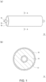
- FIG. 1 is a schematic external view of a charging roll for electrophotographic device according to an embodiment of the present invention
- (b) of FIG. 1 is a cross-sectional view thereof taken along the line A-A.
- FIG. 1 is a schematic external view of the charging roll for electrophotographic device according to an embodiment of the present invention
- FIG. 1 is a cross-sectional view thereof taken along the line A-A.
- the charging roll 10 includes a shaft 12, an elastic body layer 14 formed on the outer peripheral surface of the shaft 12, and a surface layer 16 formed on the outer peripheral surface of the elastic body layer 14.
- the elastic body layer 14 is a layer (base layer) serving as the base of the charging roll 10.
- the surface layer 16 is a layer that appears on the surface of the charging roll 10.
- an intermediate layer such as a resistance adjustment layer may be formed between the elastic body layer 14 and the surface layer 16 if necessary.
- the shaft 12 is not particularly limited as long as the shaft 12 has conductivity. Specifically, a solid body made of metal such as iron, stainless steel, or aluminum, or a core metal made of a hollow body can be exemplified. An adhesive, a primer, or the like may be applied to the surface of the shaft 12 if necessary. In other words, the elastic body layer 14 may be adhered to the shaft 12 via an adhesive layer (primer layer). The adhesive, the primer, or the like may be conductive if necessary.
- the elastic body layer 14 contains crosslinked rubber.
- the elastic body layer 14 is formed of a conductive rubber composition containing uncrosslinked rubber.
- the crosslinked rubber is obtained by crosslinking the uncrosslinked rubber.
- the uncrosslinked rubber may be polar rubber or non-polar rubber.
- the polar rubber is rubber having a polar group, and examples of the polar group include a chloro group, a nitrile group, a carboxyl group, an epoxy group, and the like.
- examples of the polar rubber include hydrin rubber, nitrile rubber (NBR), urethane rubber (U), acrylic rubber (a copolymer of acrylic acid ester and 2-chloroethyl vinyl ether, ACM), chloroprene rubber (CR), epoxidized natural rubber (ENR), and the like.
- polar rubber hydrin rubber and nitrile rubber (NBR) are more preferable from the viewpoint that the volume resistivity tends to be particularly low.
- hydrin rubber examples include epichlorohydrin homopolymer (CO), epichlorohydrin-ethylene oxide binary copolymer (ECO), epichlorohydrin-allyl glycidyl ether binary copolymer (GCO), epichlorohydrin-ethylene oxide-allyl glycidyl ether terpolymer (GECO), and the like.
- CO epichlorohydrin homopolymer
- ECO epichlorohydrin-ethylene oxide binary copolymer
- GCO epichlorohydrin-allyl glycidyl ether binary copolymer
- GECO epichlorohydrin-ethylene oxide-allyl glycidyl ether terpolymer
- urethane rubber examples include polyether-type urethane rubber having an ether bond in the molecule.
- Polyether-type urethane rubber can be produced by reacting polyether having hydroxyl groups at both ends with diisocyanate.
- polyether examples include, but are not particularly limited to, polyethylene glycol, polypropylene glycol, and the like.
- diisocyanate examples include, but are not particularly limited to, tolylene diisocyanate, diphenylmethane diisocyanate, and the like.
- non-polar rubber examples include silicone rubber (Q), isoprene rubber (IR), natural rubber (NR), styrene butadiene rubber (SBR), butadiene rubber (BR), and the like.
- isoprene rubber is more preferable from the viewpoint of excellent tensile properties.
- crosslinking agent examples include a sulfur crosslinking agent, a peroxide crosslinking agent, and a dechlorination crosslinking agent. These crosslinking agents may be used alone or in combination of two or more.
- sulfur crosslinking agent examples include conventionally known sulfur crosslinking agents such as powdered sulfur, precipitated sulfur, colloidal sulfur, surface-treated sulfur, insoluble sulfur, sulfur chloride, a thiuram-based vulcanization accelerator, polymeric polysulfide, and the like.
- peroxide crosslinking agent examples include conventionally known peroxide crosslinking agents such as peroxyketal, dialkyl peroxide, peroxy ester, ketone peroxide, peroxydicarbonate, diacyl peroxide, hydroperoxide, and the like.
- Examples of the dechlorination crosslinking agent include a dithiocarbonate compound. More specifically, examples of the dechlorination crosslinking agent include quinoxaline-2,3-dithiocarbonate, 6-methylquinoxaline-2,3-dithiocarbonate, 6-isopropylquinoxaline-2,3-dithiocarbonate, 5,8-dimethylquinoxaline-2,3-dithiocarbonate, and the like.
- the amount of the crosslinking agent to be mixed is preferably within the range of 0.1 to 2 parts by mass, more preferably within the range of 0.3 to 1.8 parts by mass, and even more preferably within the range of 0.5 to 1.5 parts by mass, based on 100 parts by mass of the uncrosslinked rubber.
- a dechlorination crosslinking accelerator may be used in combination.
- the dechlorination crosslinking accelerator include 1,8-diazabicyclo(5,4,0)undecene-7 (hereinafter abbreviated as DBU) or weak acid salt thereof.
- DBU 1,8-diazabicyclo(5,4,0)undecene-7
- the dechlorination crosslinking accelerator may be used in the form of DBU, but from the viewpoint of handling, the dechlorination crosslinking accelerator is preferably used in the form of weak acid salt thereof.
- Examples of the weak acid salt of DBU include carbonate, stearate, 2-ethylhexylate, benzoate, salicylate, 3-hydroxy-2-naphthoate, phenol resin salt, 2-mercaptobenzothiazole salt, 2-mercaptobenzimidazole salt, and the like.
- the content of the dechlorination crosslinking accelerator is preferably within the range of 0.1 to 2 parts by mass based on 100 parts by mass of the uncrosslinked rubber.
- the content of the dechlorination crosslinking accelerator is more preferably within the range of 0.3 to 1.8 parts by mass, and even more preferably within the range of 0.5 to 1.5 parts by mass.
- a conductive agent can be added to the elastic body layer 14 to impart conductivity.
- the conductive agent include an electronic conductive agent and an ionic conductive agent.
- the electronic conductive agent include carbon black, graphite, and conductive metal oxide.
- the conductive metal oxide include conductive titanium oxide, conductive zinc oxide, conductive tin oxide, and the like.
- the ionic conductive agent include quaternary ammonium salt, borate, a surfactant, and the like. Further, various additives may be added to the elastic body layer 14 if necessary.
- additives examples include lubricants, vulcanization accelerators, anti-aging agents, light stabilizers, viscosity modifiers, processing aids, flame retardants, plasticizers, foaming agents, fillers, dispersants, anti-foaming agents, pigments, release agents, and the like.
- the elastic body layer 14 can be adjusted to have a predetermined volume resistivity by adjusting the type of the crosslinked rubber, the amount of the ionic conductive agent to be mixed, the amount of the electronic conductive agent, and the like.
- the volume resistivity of the elastic body layer 14 may be appropriately set within the range of 10 2 to 10 10 ⁇ cm, 10 3 to 10 9 ⁇ cm, 10 4 to 10 8 ⁇ cm, or the like, depending on the application.
- the thickness of the elastic body layer 14 is not particularly limited, and may be appropriately set within the range of 0.1 to 10 mm depending on the application.
- the surface layer 16 includes a binder polymer and metal oxide particles.
- the surface layer 16 may further include roughness-forming particles.
- the binder polymer is a base polymer that constitutes the surface layer 16.
- the binder polymer include urethane resin, polyamide resin, acrylic resin, acrylic silicone resin, butyral resin (PVB), alkyd resin, polyester resin, fluororubber, fluororesin, a mixture of fluororubber and fluororesin, silicone resin, a silicone-grafted acrylic polymer, an acrylic-grafted silicone polymer, nitrile rubber, urethane rubber, and the like.
- a polymer having a carbonyl group is preferable. This is because a polymer having a carbonyl group is a material with a relatively high dielectric constant, allowing the charging roll 10 to easily ensure excellent chargeability.
- the polymer having a carbonyl group include urethane resin, polyamide resin, acrylic resin, acrylic silicone resin, a silicone-grafted acrylic polymer, an acrylic-grafted silicone polymer, urethane rubber, and the like.
- polyamide resin, acrylic resin, acrylic silicone resin, a silicone-grafted acrylic polymer, and an acrylic-grafted silicone polymer are particularly preferable.
- the polyamide resin may be modified. Examples of the modified polyamide include alkoxylated polyamide such as N-methoxymethylated nylon, and the like.
- the metal oxide particles function as a conductive agent for the surface layer 16.
- the metal oxide particles are conductive metal oxide particles.
- a part or the entirety of the surface of the metal oxide particles in the surface layer 16 is covered with a fluorine-based anionic surface modifier.
- a part of the surface of the metal oxide particles may be covered with a fluorine-based anionic surface modifier, or the entire surface may be covered with a fluorine-based anionic surface modifier.
- a part of the surface refers to preferably 30% or more of the surface of the metal oxide particles in terms of area, more preferably 50% or more, and even more preferably 70% or more. In the case where a part of the surface is covered, the portion covered with the fluorine-based anionic surface modifier needs to be dispersed over the entire surface of the metal oxide particles.
- Polar functional groups such as hydroxyl groups and carboxyl groups are present on the surface of the metal oxide particles.
- the fluorine-based anionic surface modifier can cover the surface of the metal oxide particles through electrostatic interaction between the anionic groups thereof and the functional groups on the surface of the metal oxide particles, which suppresses agglomeration of the metal oxide particles.
- the fluorine-containing groups thereof are oriented toward the outside of the metal oxide particles.
- the fluorine-containing groups oriented on the surface of the metal oxide particles toward the outside of the metal oxide particles reduce the friction at the interface between the metal oxide particles and the binder polymer, thereby alleviating the shear stress applied to the binder polymer. These suppress cracks in the surface layer 16 caused by the surface layer material.
- the surface modifier is cationic or nonionic rather than anionic, the surface modifier cannot interact with the functional groups on the surface of the metal oxide particles and cannot cover the surface of the metal oxide particles. Furthermore, if the surface modifier is not a fluorine-based agent but a silicone-based agent, the effect of reducing the friction at the interface between the metal oxide particles and the binder polymer is not sufficient. In addition, if carbon black is used instead of metal oxide particles, the surface functional groups of carbon black are less likely to interact with the fluorine-based anionic surface modifier, so the fluorine-based anionic surface modifier cannot cover the surface of carbon black well.
- the metal oxide particles are not particularly limited as long as the metal oxide particles have excellent conductivity.
- the metal oxide particles include tin oxide particles, zinc oxide particles, indium oxide particles, titanium oxide particles, and the like. Among these, tin oxide particles are particularly preferable from the viewpoint of exhibiting stable interaction over a wide temperature range.
- the particle diameter (primary particle diameter) of the metal oxide particles is not particularly limited, but is preferably 0.001 ⁇ m or more and 0.5 ⁇ m or less from the viewpoint of image uniformity.
- the particle diameter is more preferably 0.005 ⁇ m or more and 0.1 ⁇ m or less.
- the diameter of the aggregate (secondary particle diameter) of the metal oxide particles is preferably 0.002 ⁇ m or more and 0.7 ⁇ m or less from the viewpoint of dispersibility.
- the diameter of the aggregate is more preferably 0.6 ⁇ m or less.
- the diameter of the aggregate of the metal oxide particles can be kept small by covering the surface of the metal oxide particles with the fluorine-based anionic surface modifier.
- the content of the metal oxide particles in the surface layer 16 is preferably 30 parts by mass or more based on 100 parts by mass of the binder polymer from the viewpoint of conductivity.
- the content is more preferably 50 parts by mass or more, and even more preferably 70 parts by mass or more.
- the content of the metal oxide particles in the surface layer 16 is preferably 200 parts by mass or less based on 100 parts by mass of the binder polymer from the viewpoint of stress dispersibility.
- the content is more preferably 150 parts by mass or less.
- the fluorine-based anionic surface modifier is used for the purposes of covering the surface of the metal oxide particles to suppress agglomeration of the metal oxide particles, modify the surface of the metal oxide particles, etc.
- the fluorine-based anionic surface modifier is used for the purposes of covering the surface of the roughness-forming particles to suppress agglomeration of the roughness-forming particles, suppress interaction between the roughness-forming particles and the metal oxide particles, modify the surface of the roughness-forming particles, etc.
- the fluorine-based anionic surface modifier has an anionic group.
- the anionic group include a carboxylate group (-COO - ), a sulfonate group (-SO 4 2- ), a phosphoric acid group, and the like.
- a carboxylate group is particularly preferable from the viewpoint of excellent balance of interaction with the functional groups on the surface of the metal oxide.
- the fluorine-based anionic surface modifier is composed of a compound having a fluorine-containing organic group (a compound having a fluorine-containing group).
- the fluorine-containing group include a fluoroalkyl group having 1 to 20 carbon atoms.
- the fluoroalkyl group may be a perfluoroalkyl group in which all hydrogen atoms of the alkyl group are substituted with fluorine atoms, or may be a fluoroalkyl group in which some hydrogen atoms of the alkyl group are substituted with fluorine atoms.
- a perfluoroalkyl group is more preferable from the viewpoint of having an excellent effect of modifying the surface of the metal oxide particles with the fluorine-containing group.
- the fluorine-containing group preferably has 6 carbon atoms or less. More preferably, the fluorine-containing group has 1 to 6 carbon atoms, and more preferably 2 to 6 carbon atoms. If the number of carbon atoms in the fluorine-containing group is 8 or more, there is a strong concern about environmental regulations, so the number of carbon atoms in the fluorine-containing group is preferably 6 or less. Furthermore, the number of carbon atoms in the fluorine-containing group is preferably 2 or more, which has an excellent effect of lowering surface tension.
- the fluorine-based anionic surface modifier preferably has one or more fluorine-containing groups in the molecule, but is particularly preferable to have one fluorine-containing group in the molecule from the viewpoint of less steric hindrance when the surface modifier is oriented on the surface of the metal oxide particles during coating treatment and excellent coating efficiency.
- the fluorine-based anionic surface modifier preferably has one or more anionic groups in the molecule, but is particularly preferable to have one anionic group in the molecule from the viewpoint of excellent uniformity of interaction with the metal oxide particles.
- the fluorine-based anionic surface modifier may be a monomolecule or a polymer.
- the fluorine-based anionic surface modifier is preferably a monomolecule rather than a polymer from the viewpoint of less hindrance when the surface modifier is oriented on the surface of the metal oxide particles during coating treatment.
- the molecular weight (number average molecular weight) of the fluorine-based anionic surface modifier is preferably 400 or more from the viewpoint of stability of the interaction state. The molecular weight is more preferably 500 or more, and even more preferably 1,000 or more. Further, the molecular weight (number average molecular weight) of the fluorine-based anionic surface modifier is preferably less than 3,000 from the viewpoint of the number of reactive groups. The molecular weight is more preferably 2,500 or less, and even more preferably 2,000 or less.
- the amount of the fluorine-based anionic surface modifier is preferably 0.1 parts by mass or more and 5.0 parts by mass or less based on 100 parts by mass of the metal oxide particles.
- the amount is more preferably 0.3 parts by mass or more and 3.0 parts by mass or less, and even more preferably 0.5 parts by mass or more and 3.0 parts by mass or less.
- the amount of the fluorine-based anionic surface modifier is preferably 0.1 parts by mass or more and 5.0 parts by mass or less based on 100 parts by mass of the metal oxide particles.
- the amount is more preferably 0.3 parts by mass or more and 3.0 parts by mass or less, and even more preferably 0.5 parts by mass or more and 3.0 parts by mass or less. Furthermore, in the case where the surface layer 16 further includes roughness-forming particles, the total amount of the fluorine-based anionic surface modifier is preferably 5.0 parts by mass or less based on 100 parts by mass of the metal oxide particles.
- the roughness-forming particles are particles for imparting roughness to the surface of the surface layer 16.
- the roughness-forming particles are particles for imparting irregularities to the surface of the surface layer 16.
- the surface irregularities of the surface layer 16 increase the discharge space between a photoreceptor and the charging roll 10 and promote discharge, thereby improving the chargeability and suppressing image defects such as horizontal streaks and unevenness.
- Resin particles, inorganic particles, and the like are used as the roughness-forming particles.
- the material of the roughness-forming particles is not particularly limited.
- the roughness-forming particles are preferably composed of a polymer having a carbonyl group. This is because a polymer having a carbonyl group is a material with a relatively high dielectric constant, allowing the charging roll 10 to easily ensure excellent chargeability.
- the polymer having a carbonyl group include urethane resin, polyamide resin, acrylic resin, acrylic silicone resin, a silicone-grafted acrylic polymer, an acrylic-grafted silicone polymer, urethane rubber, and the like. Among these, from the viewpoint of excellent wear resistance, polyamide resin, acrylic resin, acrylic silicone resin, a silicone-grafted acrylic polymer, and an acrylic-grafted silicone polymer are particularly preferable.
- a part or the entirety of the surface of the roughness-forming particles is preferably covered with the fluorine-based anionic surface modifier.
- the surface of the roughness-forming particles is covered with the fluorine-based anionic surface modifier, the interaction between the polar functional groups present on the surface of the roughness-forming particles and the functional groups on the surface of the metal oxide particles is reduced, the metal oxide particles are less likely to gather on the surface of the roughness-forming particles, stress concentration due to agglomeration of the metal oxide particles on the surface of the roughness-forming particles is suppressed, and the occurrence of cracks due to shear stress in the binder polymer of the surface layer 16 is easily suppressed.
- a part of the surface refers to preferably 30% or more of the surface of the roughness-forming particles in terms of area, more preferably 50% or more, and even more preferably 70% or more. In the case where a part of the surface is covered, the portion covered with the fluorine-based anionic surface modifier needs to be dispersed over the entire surface of the roughness-forming particles.
- the fluorine-based anionic surface modifier that covers the surface of the roughness-forming particles is the same as the fluorine-based anionic surface modifier used for covering the surface of the metal oxide described above.
- the fluorine-based anionic surface modifier that covers the surface of the roughness-forming particles may be the same as or different from the fluorine-based anionic surface modifier that covers the surface of the metal oxide.
- the size of the roughness-forming particles is not particularly limited, but from the viewpoint of easily ensuring uniform chargeability, the average particle diameter is preferably 3.0 ⁇ m or more and 50 ⁇ m or less. More preferably, the average particle diameter is 5.0 ⁇ m or more and 30 ⁇ m or less.
- the average particle diameter of the roughness-forming particles is expressed as the average of 20 arbitrary points when the surface of the surface layer 16 is observed with a laser microscope, and the diameter of the roughness-forming particles 16 that can be seen during surface observation is defined as the particle diameter.
- the content of the roughness-forming particles in the surface layer 16 is not particularly limited, but from the viewpoint of easily ensuring uniform chargeability, the content is preferably 3 parts by mass or more and 50 parts by mass or less based on 100 parts by mass of the binder polymer of the surface layer 16. The content is more preferably 5 parts by mass or more and 30 parts by mass or less.
- additives may be added to the surface layer 16 if necessary.
- the additives include plasticizers, leveling agents, fillers, vulcanization accelerators, processing aids, release agents, and the like.
- the volume resistivity of the surface layer 16 is preferably set in a semiconductive region from the viewpoint of chargeability. Specifically, the volume resistivity may be set within the range of 1.0 ⁇ 10 7 to 1.0 ⁇ 10 10 ⁇ cm, for example. Volume resistivity can be measured in accordance with JIS K6911.
- the thickness of the surface layer 16 is not particularly limited, and is preferably set within the range of 0.1 to 30 ⁇ m. The thickness of the surface layer 16 can be measured by observing the cross section using a laser microscope (for example, "VK-9510" or the like manufactured by Keyence Corporation). For example, the distance from the surface of the elastic body layer 14 to the surface of the surface layer 16 can be measured at five arbitrary positions, and the thickness can be expressed as the average of the distances.
- the elastic body layer 14 can be formed, for example, as follows. First, the shaft 12 is coaxially installed in the hollow part of a roll molding die, and an uncrosslinked conductive rubber composition is injected. After heating and curing (crosslinking), the elastic body layer 14 is formed on the outer periphery of the shaft 12 by demolding or by extruding the uncrosslinked conductive rubber composition on the surface of the shaft 12.
- the surface layer 16 can be formed by applying the material forming the surface layer 16 onto the outer peripheral surface of the elastic body layer 14 and appropriately performing a drying treatment or the like.
- the material forming the surface layer 16 may include a diluting solvent.
- the diluting solvent include ketone solvents such as methyl ethyl ketone (MEK) and methyl isobutyl ketone, alcohol solvents such as isopropyl alcohol (IPA), methanol, and ethanol, hydrocarbon solvents such as hexane and toluene, acetic acid solvents such as ethyl acetate and butyl acetate, ether solvents such as diethyl ether and tetrahydrofuran, water, and the like.
- ketone solvents such as methyl ethyl ketone (MEK) and methyl isobutyl ketone
- alcohol solvents such as isopropyl alcohol (IPA), methanol, and ethanol
- hydrocarbon solvents
- the material forming the surface layer 16 includes the binder polymer and the metal oxide particles.
- the material forming the surface layer 16 may further include roughness-forming particles if necessary. As described above, a part or the entirety of the surface of the metal oxide particles is covered with the fluorine-based anionic surface modifier. Further, as described above, a part or the entirety of the surface of the roughness-forming particles is covered with the fluorine-based anionic surface modifier.
- the material forming the surface layer 16 may be prepared as follows. First, the metal oxide particles and the fluorine-based anionic surface modifier are mixed, and a part or the entirety of the surface of the metal oxide particles is covered with the fluorine-based anionic surface modifier. Next, the metal oxide particles whose surface is partially or completely covered with the fluorine-based anionic surface modifier is mixed with the binder polymer. In this way, the metal oxide particles are first mixed with the fluorine-based anionic surface modifier before being mixed with the binder polymer, making it possible to cover a part or the entirety of the surface of the metal oxide particles with the fluorine-based anionic surface modifier.
- the roughness-forming particles may also be mixed with the fluorine-based anionic surface modifier before being mixed with the binder polymer. Thereby, a part or the entirety of the surface of the roughness-forming particles can be covered with the fluorine-based anionic surface modifier.
- the metal oxide particles and the roughness-forming particles may be mixed together with the fluorine-based anionic surface modifier before being mixed with the binder polymer, or may be mixed separately with the fluorine-based anionic surface modifier. In the case where the metal oxide particles and the roughness-forming particles are mixed separately, the effect of covering the surface of each particle and the effect of suppressing agglomeration of the metal oxide particles on the surface of the roughness-forming particles are enhanced.
- the charging roll 10 having the above configuration, a part or the entirety of the surface of the metal oxide particles contained in the surface layer 16 is covered with the fluorine-based anionic surface modifier, so agglomeration of the metal oxide particles is suppressed.
- the fluorine-containing groups oriented toward the outside of the metal oxide particles reduce the friction at the interface between the metal oxide particles and the binder polymer, thereby alleviating the shear stress applied to the binder polymer. As a result, cracks in the surface layer 16 caused by the surface layer material are suppressed.
- the resistance unevenness of the surface layer 16 is determined by randomly measuring the resistance at 100 points on the surface of the surface layer 16 using AFM, and can be expressed as the ratio of the difference between the maximum and minimum resistance values to the average resistance value of 100 points ((maximum resistance value-minimum resistance value)/average resistance value).
- the above ratio decreases to about 15% in the case where a part or the entirety of the surface of the metal oxide particles included in the surface layer 16 is covered with the fluorine-based anionic surface modifier, and increases to about 30% in the case where a part or the entirety of the surface of the metal oxide particles included in the surface layer 16 is not covered with the fluorine-based anionic surface modifier (in the case where the resistance unevenness is large).
- the metal oxide particles are less likely to gather on the surface of the roughness-forming particles, stress concentration due to agglomeration of the metal oxide particles on the surface of the roughness-forming particles is suppressed, and the occurrence of cracks due to shear stress in the binder polymer of the surface layer 16 is easily suppressed. Further, since the friction on the surface of the roughness-forming particles is also reduced, the occurrence of cracks due to shear stress at the interface between the roughness-forming particles and the binder polymer is also suppressed.
- a vulcanization aid (zinc oxide, "zinc oxide 2 type” manufactured by Mitsui Kinzoku), 10 parts by mass of carbon ("Ketjenblack EC300J” manufactured by Ketjen Black International), 0.5 parts by mass of a vulcanization accelerator (2-mercaptobenzothiazole, "Noxeller M-P” manufactured by Ouchi Shinko Chemical Industrial Co., Ltd.), 2 parts by mass of sulfur (“Sulfax PTC” manufactured by Tsurumi Chemical Industry Co., Ltd.), and 50 parts by mass of a filler (calcium carbonate, "HAKUENKA CC” manufactured by Shiraishi Kogyo Kaisha, Ltd.) were added to 100 parts by mass of hydrin rubber (ECO, "Epichromer CG102” manufactured by Daiso Co., Ltd.), and these were stirred and mixed with a stirrer to prepare a conductive rubber composition.
- a vulcanization aid zinc oxide, "zinc oxide 2 type” manufactured by Mitsui Kin
- a shaft (diameter 8 mm) made of a nickel-plated iron core metal was set in a molding die (pipe shape), the above elastic body layer composition was injected, and after heating at 180°C for 30 minutes, cooling and demolding were performed to form an elastic body layer composed of a conductive rubber elastic body with a thickness of 1.9 mm on the outer periphery of the core metal.
- a fluorine-based anionic surface modifier 0.7 parts by mass of a fluorine-based anionic surface modifier was blended with 100 parts by mass of metal oxide, 100 parts by mass of MEK was added, and the mixture was stirred at 40°C or lower for 30 minutes. Through the above, metal oxide coated with the fluorine-based anionic surface modifier was obtained.
- a surface layer forming composition 50 parts by mass of melamine resin, 100 parts by mass of metal oxide particles coated with the fluorine-based anionic surface modifier, and 50 parts by mass of the roughness-forming particles coated with the fluorine-based anionic surface modifier were blended with 100 parts by mass of polyamide resin (binder polymer), and 100 parts by mass of MEK was mixed to prepare a surface layer forming composition.
- the surface layer forming composition was roll coated on the outer peripheral surface of the elastic body layer, and heat treatment was performed to form a surface layer with a thickness of 10 ⁇ m on the outer periphery of the elastic body layer. In this way, a charging roll was produced.
- the surface layer material was composed of the compounding composition shown in Table 1.
- the base polymer was changed from hydrin rubber to isoprene rubber (IR, "JSR IR2200” manufactured by JSR).
- the charging roll was produced in the same manner as in Example 1 except that the surface layer material was not coated with metal oxide particles.
- the charging roll was produced in the same manner as in Example 1 except that carbon black was used as the conductive agent in place of the metal oxide particles in the surface layer material.
- the charging roll was produced in the same manner as in Comparative Example 2 except that the surface layer material was not coated with carbon black as a conductive agent.
- the charging roll was produced in the same manner as in Example 10 except that the surface modifier was changed in the surface layer material.
- the materials used for the surface layer are as follows.
- the prepared charging roll was attached to the unit (black) of an actual machine ("MP C6004" manufactured by RICOH), and an evaluation (streak evaluation) was carried out after printing 500,000 sheets of images at 25% density halftone in an environment of 10°C and 10% RH.
- An example in which no streak image was generated due to cracks in the surface layer was rated as "O”
- an example in which a streak image was generated due to cracks in the surface layer was rated as "X”.
- Comparative Example 1 the surface of the metal oxide particles was not coated with a surface modifier. Therefore, agglomeration of the metal oxide particles was not suppressed, and cracks in the surface layer due to the surface layer material were not suppressed.
- the conductive agent was carbon black.
- carbon black was surface-treated using a surface modifier, but the surface functional groups of carbon black had difficulty interacting with the surface modifier, so the coating treatment was not effective and agglomeration was not suppressed. Therefore, in Comparative Example 2, cracks in the surface layer due to the surface layer material were not suppressed.
- Comparative Example 3 the surface of carbon black was not coated with a surface modifier. Therefore, agglomeration of carbon black was not suppressed, and cracks in the surface layer due to the surface layer material were not suppressed.
- the surface modifier was a fluorine-based cationic surface modifier.
- the surface modifier was a fluorine-based nonionic surface modifier.
- the surface modifier did not interact with the surface functional groups of the metal oxide particles, so the metal oxide particles were not coated with the surface modifier, and agglomeration of the metal oxide particles was not suppressed. Therefore, in Comparative Examples 4 to 6, cracks in the surface layer due to the surface layer material were not suppressed.
- the surface modifier was a silicone-based anionic surface modifier.
- Comparative Example 7 Although the metal oxide particles were coated with the surface modifier, there was no fluorine-containing group oriented toward the outside of the metal oxide particles, so the effect of reducing the friction at the interface between the metal oxide particles and the binder polymer was insufficient, and cracks in the surface layer due to the surface layer material were not suppressed.
- the metal oxide particles were used as the conductive agent, and the surface of the metal oxide particles was covered with the fluorine-based anionic surface modifier. Therefore, agglomeration of the metal oxide particles was suppressed.
- the fluorine-containing groups oriented toward the outside of the metal oxide particles reduced the friction at the interface between the metal oxide particles and the binder polymer, and alleviated the shear stress applied to the binder polymer. As a result, cracks in the surface layer caused by the surface layer material were suppressed.
Landscapes
- Physics & Mathematics (AREA)
- Engineering & Computer Science (AREA)
- Plasma & Fusion (AREA)
- General Physics & Mathematics (AREA)
- Electrostatic Charge, Transfer And Separation In Electrography (AREA)
- Rolls And Other Rotary Bodies (AREA)
Applications Claiming Priority (2)
| Application Number | Priority Date | Filing Date | Title |
|---|---|---|---|
| JP2021214583A JP7710979B2 (ja) | 2021-12-28 | 2021-12-28 | 電子写真機器用帯電ロールおよび電子写真機器用帯電ロールの製造方法 |
| PCT/JP2022/044507 WO2023127398A1 (ja) | 2021-12-28 | 2022-12-02 | 電子写真機器用帯電ロールおよび電子写真機器用帯電ロールの製造方法 |
Publications (2)
| Publication Number | Publication Date |
|---|---|
| EP4428618A1 true EP4428618A1 (de) | 2024-09-11 |
| EP4428618A4 EP4428618A4 (de) | 2025-02-26 |
Family
ID=86998566
Family Applications (1)
| Application Number | Title | Priority Date | Filing Date |
|---|---|---|---|
| EP22915629.4A Pending EP4428618A4 (de) | 2021-12-28 | 2022-12-02 | Aufladerolle für elektrofotografische vorrichtungen und verfahren zur herstellung einer aufladerolle für elektrofotografische vorrichtungen |
Country Status (5)
| Country | Link |
|---|---|
| US (1) | US20240272563A1 (de) |
| EP (1) | EP4428618A4 (de) |
| JP (1) | JP7710979B2 (de) |
| CN (1) | CN118202307A (de) |
| WO (1) | WO2023127398A1 (de) |
Family Cites Families (5)
| Publication number | Priority date | Publication date | Assignee | Title |
|---|---|---|---|---|
| JP3796400B2 (ja) | 1999-09-30 | 2006-07-12 | キヤノン株式会社 | 導電部材、プロセスカートリッジ及び画像形成装置 |
| JP2003140439A (ja) | 2001-11-01 | 2003-05-14 | Bridgestone Corp | 帯電部材及び帯電装置 |
| JP2005255913A (ja) | 2004-03-12 | 2005-09-22 | Dainippon Printing Co Ltd | コーティング組成物、その塗膜、反射防止膜、及び画像表示装置 |
| JP6346494B2 (ja) * | 2014-05-16 | 2018-06-20 | キヤノン株式会社 | 電子写真用部材、プロセスカートリッジおよび電子写真装置 |
| JP7623135B2 (ja) * | 2020-12-24 | 2025-01-28 | 住友理工株式会社 | 電子写真機器用帯電ロール |
-
2021
- 2021-12-28 JP JP2021214583A patent/JP7710979B2/ja active Active
-
2022
- 2022-12-02 CN CN202280073749.1A patent/CN118202307A/zh active Pending
- 2022-12-02 EP EP22915629.4A patent/EP4428618A4/de active Pending
- 2022-12-02 WO PCT/JP2022/044507 patent/WO2023127398A1/ja not_active Ceased
-
2024
- 2024-04-09 US US18/629,938 patent/US20240272563A1/en active Pending
Also Published As
| Publication number | Publication date |
|---|---|
| JP7710979B2 (ja) | 2025-07-22 |
| US20240272563A1 (en) | 2024-08-15 |
| CN118202307A (zh) | 2024-06-14 |
| JP2023098075A (ja) | 2023-07-10 |
| EP4428618A4 (de) | 2025-02-26 |
| WO2023127398A1 (ja) | 2023-07-06 |
Similar Documents
| Publication | Publication Date | Title |
|---|---|---|
| US10444655B2 (en) | Charging roll for electrophotographic equipment | |
| US20120288306A1 (en) | Conductive member for electrophotographic device | |
| JP2014065811A (ja) | 電子写真機器用導電性ゴム組成物およびこれを用いた電子写真機器用導電性部材 | |
| US12013650B2 (en) | Charging roll for electrophotographic apparatus | |
| US10656555B2 (en) | Development roll for electrophotography device | |
| EP4428618A1 (de) | Aufladerolle für elektrofotografische vorrichtungen und verfahren zur herstellung einer aufladerolle für elektrofotografische vorrichtungen | |
| JP2021096377A (ja) | 電子写真機器用導電性ロール | |
| US12578667B2 (en) | Charging roll for electrophotographic machine | |
| CN108027578A (zh) | 电子照相设备用带电辊 | |
| JP7623135B2 (ja) | 電子写真機器用帯電ロール | |
| JP6722613B2 (ja) | 電子写真機器用帯電ロール | |
| JP7717885B1 (ja) | 電子写真機器用帯電ロール | |
| CN112771277B (zh) | 电子照相设备用带电辊 | |
| JP6850210B2 (ja) | 電子写真機器用帯電部材 | |
| JP7840229B2 (ja) | 電子写真機器用帯電ロール | |
| JP7788483B2 (ja) | 電子写真機器用帯電ロール | |
| JP7655835B2 (ja) | 電子写真機器用帯電ロールおよび電子写真機器用帯電ロールの製造方法 | |
| JP2021189208A (ja) | 電子写真機器用帯電ロール | |
| JP7079719B2 (ja) | 電子写真機器用導電性部材 | |
| JP2021051232A (ja) | 電子写真機器用帯電ロール |
Legal Events
| Date | Code | Title | Description |
|---|---|---|---|
| STAA | Information on the status of an ep patent application or granted ep patent |
Free format text: STATUS: THE INTERNATIONAL PUBLICATION HAS BEEN MADE |
|
| PUAI | Public reference made under article 153(3) epc to a published international application that has entered the european phase |
Free format text: ORIGINAL CODE: 0009012 |
|
| STAA | Information on the status of an ep patent application or granted ep patent |
Free format text: STATUS: REQUEST FOR EXAMINATION WAS MADE |
|
| 17P | Request for examination filed |
Effective date: 20240603 |
|
| AK | Designated contracting states |
Kind code of ref document: A1 Designated state(s): AL AT BE BG CH CY CZ DE DK EE ES FI FR GB GR HR HU IE IS IT LI LT LU LV MC ME MK MT NL NO PL PT RO RS SE SI SK SM TR |
|
| A4 | Supplementary search report drawn up and despatched |
Effective date: 20250127 |
|
| RIC1 | Information provided on ipc code assigned before grant |
Ipc: G03G 15/02 20060101AFI20250121BHEP |
|
| DAV | Request for validation of the european patent (deleted) | ||
| DAX | Request for extension of the european patent (deleted) |