EP4428301A1 - Vorrichtung für eine beheizte zellstoffpresse mit integralen elementen für verbesserte effizienz - Google Patents
Vorrichtung für eine beheizte zellstoffpresse mit integralen elementen für verbesserte effizienz Download PDFInfo
- Publication number
- EP4428301A1 EP4428301A1 EP24161880.0A EP24161880A EP4428301A1 EP 4428301 A1 EP4428301 A1 EP 4428301A1 EP 24161880 A EP24161880 A EP 24161880A EP 4428301 A1 EP4428301 A1 EP 4428301A1
- Authority
- EP
- European Patent Office
- Prior art keywords
- tooling
- assembly
- heater plate
- grooves
- split heater
- Prior art date
- Legal status (The legal status is an assumption and is not a legal conclusion. Google has not performed a legal analysis and makes no representation as to the accuracy of the status listed.)
- Pending
Links
Images


Classifications
-
- B—PERFORMING OPERATIONS; TRANSPORTING
- B30—PRESSES
- B30B—PRESSES IN GENERAL
- B30B15/00—Details of, or accessories for, presses; Auxiliary measures in connection with pressing
- B30B15/34—Heating or cooling presses or parts thereof
-
- B—PERFORMING OPERATIONS; TRANSPORTING
- B30—PRESSES
- B30B—PRESSES IN GENERAL
- B30B11/00—Presses specially adapted for forming shaped articles from material in particulate or plastic state, e.g. briquetting presses, tabletting presses
- B30B11/02—Presses specially adapted for forming shaped articles from material in particulate or plastic state, e.g. briquetting presses, tabletting presses using a ram exerting pressure on the material in a moulding space
- B30B11/04—Presses specially adapted for forming shaped articles from material in particulate or plastic state, e.g. briquetting presses, tabletting presses using a ram exerting pressure on the material in a moulding space co-operating with a fixed mould
-
- D—TEXTILES; PAPER
- D21—PAPER-MAKING; PRODUCTION OF CELLULOSE
- D21F—PAPER-MAKING MACHINES; METHODS OF PRODUCING PAPER THEREON
- D21F13/00—Making discontinuous sheets of paper, pulpboard or cardboard, or of wet web, for fibreboard production
-
- D—TEXTILES; PAPER
- D21—PAPER-MAKING; PRODUCTION OF CELLULOSE
- D21J—FIBREBOARD; MANUFACTURE OF ARTICLES FROM CELLULOSIC FIBROUS SUSPENSIONS OR FROM PAPIER-MACHE
- D21J3/00—Manufacture of articles by pressing wet fibre pulp, or papier-mâché, between moulds
Definitions
- the present invention relates to apparatus and methods of making molded pulp products using an industrial press fitted with specialized, heated tooling and, more particularly, to a heater plate arrangement for such operations in which a cartridge heater element is disposed
- United States Patent 3,305,434 describes a manufacturing method for pressed paperboard stock with high moisture content in which pressure, heat, and suction are used to form the final product.
- This patent recognizes and addresses the specific issues associated with the evolution of steam and vapor, including how to vent and remove the same from the die/press. Notably, it relies on permanent heating elements positioned beneath and affixed to the base of the die itself.
- United States Patent 9,011,308 provides further information on the state of the art.
- United States Patent 8,545,202 proposes molding machine in which the rim of a cardboard-pressed base is sealed by movable collar and seal rings, so as to allow alterations to the base in order to create different products.
- United States Patent Publication 2016/0368235 describes processes for molding wet paper blanks. The process relies on clamping and heating two cooperating molds to define a cavity, with special considerations for detaching/cutting the resulting paper product from the molds.
- a pulp molding machine includes a heated press that dries and finishes various types of molded pulp products.
- the size, shape, and basic functionality of the product will vary depending upon the tooling fitted to the press.
- the tooling will include a plurality of upper and lower dies which, when coupled together, define a cavity that is filled by pulp.
- the molding machine will employ a split heater plate assembly.
- This assembly has a laminar construction, with an insulator plate, a lower/bottom heating element plate, and an upper/top tooling plate.
- Cartridge heating elements are disposed in a series of regular formed channels in the heating element plate, while the tooling plate includes channels for management of fluids (liquid and/or gas) that may be encountered during the molding and pressing process.
- Electrical and fluid management manifolds and connections are provided to allow integration of the assembly into any number of pressing apparatus commonly found in pulp molding machines.
- the tooling is affixed to the top tooling plate without the need to disrupt the cartridge heaters, whereas the close proximity of those heaters to the cartridge heaters eliminates direct and/or additional heating elements connected to individual tools, thereby enabling a pulp molding machine whose tooling can be quickly changed out, with a resultant reduction in errors owing to the elimination of individual wiring arrangements for each tool set.
- the words “example” and “exemplary” mean an instance or illustration of broader concept; however, use of these words do not necessarily indicate a required, key, or preferred aspect or embodiment.
- the word “or” is intended to be inclusive rather an exclusive, unless context suggests otherwise.
- the phrase “A employs B or C,” includes any inclusive permutation (e.g., A employs B; A employs C; or A employs both B and C).
- the articles “a” and “an” are generally intended to mean “one or more” unless context suggest otherwise.
- the inventors observed up to a 60° C gradient between the set temperature of heating elements associated with the press and the actual surface temperature of the tool/die itself.
- the gradient is so great that it becomes impractical to compensate for it by using a higher set temperature, especially in situations where that set temperature might approach or exceed the softening or melting point of the materials used to construct the tool itself (e.g., most of the common aluminum alloys used for tooling will soften to less than one half their original yield strength well before approaching the actual melting point of the alloy/metal).
- the solution requires a plurality of individual heating elements associated with each tool.
- each element had to be unwired and rewired whenever the tooling was changed (e.g., in order to change the type of molded product being produced). This resulted in more downtime and slower production times for the press/manufacturing operation.
- a pulp molding machine 1 includes a heated press assembly 2.
- a heated press assembly 2 Generally speaking, during molding operations, two opposing plates, each carrying a cooperating tool or die shaped to form a molded pulp product, are brought together.
- Wet pulp i.e., having a soft but pliable form, usually with a solids content of ⁇ 50 wt.% is positioned between or provided to the interstices between the cooperating tools/dies, which will eventually be joined together to confine and further process the wet pulp into a desired final shape.
- the assembly 2 also includes fluid manifold structures 36 to manage the various liquids and gases evolved from or involved with this molding operation.
- the manifolds 36 will be fluidically connected to relevant channels on the press plates, as well other venting and supply tubes within the machine 1.
- the machine 1 will also contain sufficient controllers to manage and sequence the various movements and operations involved with the molding process. The end result is that a sufficient amount of moisture content will be removed from the wet pulp during the molding process to allow for the resultant pulp product to be handled, packaged, or otherwise processed further (depending upon the nature of the product and the configuration of the manufacturing line)
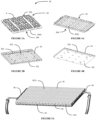
- split plate heater assembly 3 has been developed to replace conventional heater plates normally found in the press assembly 2.
- the split heater plate assembly generally comprises two flat planar members 33, 35 coupled together and fixed to the press assembly 2 opposite a cooperating plate 22.
- this plate 22 is provided on the top portion of the press assembly 2 and it carries interchangeable tooling/dies 4, although it will be understood that a split heater plate could be implemented here as well.
- Members 33, 35 should have comparable thicknesses and similar and cooperating peripheral shapes, usually rectilinear so as to be easily confined within the machine 1 while maximizing the number of-and even more preferably the most efficient spacing for the individual tool/dies 4. Square and rectangular shapes are most common.
- the members 33, 35 are also preferably made from the same material or materials having similar heat expansion and other thermal properties.
- the lower or bottom member 33 includes a top facing 335.
- a series of grooves 331 are formed in this facing 335, with the grooves having a rounded shape that conforms to the contours of a series of cartridge heaters 34 that may be placed within the groove 331.
- the grooves 331 are spaced apart and preferably rounded channels running on a straight line from one edge 333 to an opposing edge 334 of the plate 33. In some aspects, all of the channels 331 are parallel and spaced apart at the same distance. In other aspects, a staggered or offset pattern might better accommodate tools 4 where features, compartments, or segments may not be symmetrical or otherwise comparably sized (although these arrangements may not be as versatile as the regularly spaced embodiment shown here).
- One or more retainer channels 332 run across the member 33 so as to intersect with each groove 331.
- Cooperating retainer elements 3321 are held within the channel 332, and these elements 3321 serve to restrain and retain the positioning of the heaters 34.
- the channels should be sized to maximize heat transfer from the heaters 34 into/toward the tools 4 (e.g., through plate 35).
- Lower base plate 33 may be carried on an insulator plate 351. It may also be imparted with threaded ports to allow attachment of the various adjacent components described herein. Other fixtures may be attached along the edges to accommodate electrical connections for the heating elements 34 and/or to facilitate mounting the plate 33 within the assembly 2 and guiding the movement of the assembly 3 within the press assembly 2.
- Top plate 35 is coupled to the base plate 33.
- Top plate 35 may include a plurality of corresponding grooves 3541 in its bottom facing 354.
- channels or other features can be provided to accommodate the retainer elements 3321, as well as any other exposed features from the bottom member 33.
- the interface between members 33, 35 should be configured to maximize heat transfer, although the provision of grooves 3541 allows the heater 34 to directly contact and heat top member 35, thereby improving efficiency.
- Top plate 35 has a top facing 352 onto which interchangeable tools or dies 4 may be attached. These tools 4 can be positioned within individual tooling receptacles 353.
- receptacles 353 may include fluid flow channels 3531 and/or fasteners 3532.
- the flow channels 3531 accommodate fluids necessarily encountered during pulp molding, and these will connect to the aforementioned manifolds 36.
- the channels 3531 may be embedded in the surface and/or tunnel (i.e., be completely encased by) the material forming the top plate 35.
- the receptacles 353 are preferably arranged in regular, spaced apart arrays. They are also positioned immediately above the grooves 331 (and optionally 3541) so that the cartridge heaters 34 can and will quickly heat the tools 4 held in the receptacles 353.
- FIG. 6 schematically illustrates key differences of the inventive split heater assembly 1 and a prior art arrangement A.: because the cartridge heaters are encased within the heater assembly, the height of the assembly is reduced. Without wishing to be bound by any particular theory of operation, the inventors believe this reduced height enables improved thermal transfer.
- assembly 1 reduces the distance from the core of heater 35 by well over 10% in comparison to prior art assembly A in which heater elements 34 are embedded in the element plate so as to eliminate the inefficiencies of other prior art designs in which the heater 35 is coupled to the tool 4 (or positioned immediately underneath it). Further, arrangement A requires an additional heat transfer junction J that is eliminated in the split plate assembly 1.
- the temperature of the outermost surface of the tooling is 78% or greater in comparison to the set temperature of the cartridge heater (e.g., if the set temperature is 100° C, the observed temperature on the outermost surface of the tool will be at least 78 ° C)).
- the conventional or typical design shown on the left side of Fig. 6 tends to take longer to arrive at a steady state and the outer tooling temperature is 75% or less in comparison to the set temperature.
- the conventional design requires more time to arrive achieve the desired and necessary temperatures to remove moisture.
- the longer time results in fewer operations per minute (i.e., the cycle time for manufacturing a part on the same pulp molding press).
- Disclosed aspects of the invention herein can be completed at least 10% and up to almost 20% more quickly than its conventional counterpart (i.e., a tool coupled to a heating plate with a standard configuration). Stated differently, the speed of molding operations using a split plate heater assembly is about 15% faster in comparison to an identical operation using a conventionally configured heater plate, both as shown in Fig. 6 .
- the split heater plate contemplated herein insures that the top plate maintains a temperature that is 98% or more in comparison to that of the bottom plate.
- This improved thermal performance within the assembly can be attributed to the elimination of a junction that was otherwise present in the typical design, as well as the comparatively shorter profile (i.e., the thickness of the plates, at least in terms of distance from the heating element to the top of the tool/die).
- each machine requires an axial/vertical driver, such as a electric, hydraulic, or pneumatic jack system.
- the tooling and heating plates will be mounted on a common frame that brings the top and bottom dies into close proximity.
- Fluid and pressure management systems are also required in order to vent vapors evolved during the pressing process, as well as to position the tools and wet pulp as may be required for manufacture of products.
- an ejection or product removal system allows for the finished and molded products to be ejected or removed from the tooling plate so that the process may be repeated. Insofar as efficiency and high speed operations are desired, these various systems and elements may be automated and controlled so as to allow the pulp molding machine to be integrated with a larger manufacturing line.
- the invention is a split heater plate assembly configured to operate in conjunction with any pulp molding machine incorporating a heated press.
- This split heater plate assembly includes a flat planar base member with a plurality of grooves disposed in a top facing; at least one elongated, cylindrical heating element seated in one of the plurality of grooves; and a flat planar top member having a bottom interfacing with the base member and the heating element(s), a top, and a peripheral a shape complimentary to the base member.
- the top member includes a plurality of tooling receptacles integrally disposed on the top, wherein each of the plurality of tooling receptacles is disposed on a top facing and aligned so as to be positioned directly above one of the heating elements. Additional aspects may include any one or combination of the following:
- the machine includes a split heater plate assembly having: i) a lower plate member with a series of spaced apart channels each running transversely across a top facing of the lower plate member, and ii) an upper plate member configured to couple to the top facing of the lower plate member so as to cover and enclose the spaced apart channels, wherein interchangeable tooling is detachably fixed to a top facing of the upper plate directly above each one of the spaced apart channels; a plurality of cartridge heaters with individual cartridge heaters seated in each of the spaced apart channels; and a tooling press assembly having interchangeable tooling detachably fixed to a lower facing.
- the split heater plate and the tooling press assembly are configured to move into close proximity during a molding operation, and/or the cartridge heaters are in thermal communication with interchangeable tooling through the upper plate member so that, after attaining steady set operation, an observed temperature on an outermost surface of the interchangeable tooling in the split heater plate is at least 78% or greater than a set temperature of the plurality of cartridge heaters.
- an observed temperature of the upper plate in the split heater plate assembly is within 98% of an observed temperature of the lower plate in the split heater plate assembly at all times during the molding operation.
- All components of the system should be made of materials having sufficient flexibility and structural integrity, as well as a chemically inert nature.
- the materials should also be selected for workability, cost, and weight. Tooling made from aluminum and alloys thereof is particularly useful. With respect to the other components, other metals (e.g., various grades of steel, zinc, etc.), alloys of such metals, and/or other composites may be used in place of or in addition to conventional materials.
- the heating elements can be electrically heated by way of resistive coils and/or ceramic heating elements.
- references to coupling are to be understood as encompassing any of the conventional means used in this field. This may take the form of snap- or force fitting of components, although threaded connections, bead-and-groove, "beverage can” and other forms of crimping, and bayonet-style/slot-and-flange assemblies could be employed. Adhesive and fasteners (screws, nut/bolt, etc.) could also be used. All coupling components must be judiciously selected so as to retain the functionality of the assembly.
- engagement may involve coupling or an abutting relationship.
Landscapes
- Engineering & Computer Science (AREA)
- Mechanical Engineering (AREA)
- Manufacturing & Machinery (AREA)
- Paper (AREA)
Applications Claiming Priority (1)
| Application Number | Priority Date | Filing Date | Title |
|---|---|---|---|
| US202363450118P | 2023-03-06 | 2023-03-06 |
Publications (1)
| Publication Number | Publication Date |
|---|---|
| EP4428301A1 true EP4428301A1 (de) | 2024-09-11 |
Family
ID=90363161
Family Applications (1)
| Application Number | Title | Priority Date | Filing Date |
|---|---|---|---|
| EP24161880.0A Pending EP4428301A1 (de) | 2023-03-06 | 2024-03-06 | Vorrichtung für eine beheizte zellstoffpresse mit integralen elementen für verbesserte effizienz |
Country Status (2)
| Country | Link |
|---|---|
| US (1) | US20240300200A1 (de) |
| EP (1) | EP4428301A1 (de) |
Families Citing this family (1)
| Publication number | Priority date | Publication date | Assignee | Title |
|---|---|---|---|---|
| US20250171963A1 (en) * | 2023-11-27 | 2025-05-29 | Brown Llc | System and method for laminating paper |
Citations (9)
| Publication number | Priority date | Publication date | Assignee | Title |
|---|---|---|---|---|
| US3305434A (en) | 1966-02-15 | 1967-02-21 | Standard Packaging Corp | Method and apparatus for forming rigid paper products from wet paperboard stock |
| US4514353A (en) | 1983-06-29 | 1985-04-30 | International Paper Company | Apparatus and method for forming a multi-compartmented tray from a sheet material |
| US6932753B1 (en) | 1998-12-09 | 2005-08-23 | Fort James Corporation | Food serving paperboard container pressing apparatus employing cast-in electrical heaters |
| CN201785677U (zh) * | 2010-08-03 | 2011-04-06 | 杭州欧亚机械制造有限公司 | 采用导热油作为加热载体的全自动植物纤维模塑成型机 |
| US8545202B2 (en) | 2008-08-12 | 2013-10-01 | Stora Enso Oyj | Mould system for manufacturing a container |
| US9011308B2 (en) | 2008-10-16 | 2015-04-21 | Quality Tools S.R.L. | Equipment and method for the forming of paper containers |
| US20160368235A1 (en) | 2015-06-16 | 2016-12-22 | Golden Arrow Printing Co., Ltd. | Hot pressing mold for pulp molding and manufacturing method thereof |
| CN215629034U (zh) * | 2021-08-13 | 2022-01-25 | 河北谷芮环保包装制品有限公司 | 便于蒸汽排放的纸浆模塑成型模具 |
| WO2022072555A1 (en) * | 2020-09-29 | 2022-04-07 | Zume, Inc. | Porous molds for molded fiber part manufacturing and method for additive manufacturing of same |
Family Cites Families (1)
| Publication number | Priority date | Publication date | Assignee | Title |
|---|---|---|---|---|
| JP7392286B2 (ja) * | 2019-05-16 | 2023-12-06 | Toppanホールディングス株式会社 | カバー材の製造方法とパルプモールド成形用型 |
-
2024
- 2024-03-06 US US18/596,805 patent/US20240300200A1/en active Pending
- 2024-03-06 EP EP24161880.0A patent/EP4428301A1/de active Pending
Patent Citations (9)
| Publication number | Priority date | Publication date | Assignee | Title |
|---|---|---|---|---|
| US3305434A (en) | 1966-02-15 | 1967-02-21 | Standard Packaging Corp | Method and apparatus for forming rigid paper products from wet paperboard stock |
| US4514353A (en) | 1983-06-29 | 1985-04-30 | International Paper Company | Apparatus and method for forming a multi-compartmented tray from a sheet material |
| US6932753B1 (en) | 1998-12-09 | 2005-08-23 | Fort James Corporation | Food serving paperboard container pressing apparatus employing cast-in electrical heaters |
| US8545202B2 (en) | 2008-08-12 | 2013-10-01 | Stora Enso Oyj | Mould system for manufacturing a container |
| US9011308B2 (en) | 2008-10-16 | 2015-04-21 | Quality Tools S.R.L. | Equipment and method for the forming of paper containers |
| CN201785677U (zh) * | 2010-08-03 | 2011-04-06 | 杭州欧亚机械制造有限公司 | 采用导热油作为加热载体的全自动植物纤维模塑成型机 |
| US20160368235A1 (en) | 2015-06-16 | 2016-12-22 | Golden Arrow Printing Co., Ltd. | Hot pressing mold for pulp molding and manufacturing method thereof |
| WO2022072555A1 (en) * | 2020-09-29 | 2022-04-07 | Zume, Inc. | Porous molds for molded fiber part manufacturing and method for additive manufacturing of same |
| CN215629034U (zh) * | 2021-08-13 | 2022-01-25 | 河北谷芮环保包装制品有限公司 | 便于蒸汽排放的纸浆模塑成型模具 |
Also Published As
| Publication number | Publication date |
|---|---|
| US20240300200A1 (en) | 2024-09-12 |
Similar Documents
| Publication | Publication Date | Title |
|---|---|---|
| EP4428301A1 (de) | Vorrichtung für eine beheizte zellstoffpresse mit integralen elementen für verbesserte effizienz | |
| EP0916427A1 (de) | Progressiver tiefziehvorrichtung | |
| CN103752672A (zh) | 一种汽车座椅连接板的成型工艺 | |
| CN114430703A (zh) | 冲压成型品的制造方法、冲压成型品以及冲压成型装置 | |
| CN111203479B (zh) | 一种面向微零件加工的模具及方法 | |
| US6860135B2 (en) | Method for removing strain from press-formed workpiece, and forming press | |
| CN110153288A (zh) | 一种钣金u形件折弯成形的模具 | |
| US8739592B2 (en) | Device for the production of molded parts | |
| KR20160136609A (ko) | 프로그레시브 성형장치 및 그 성형방법 | |
| KR20160109489A (ko) | 온간 프레스 금형장치, 및 이를 이용한 성형 방법 | |
| CN219786561U (zh) | 一种钨合金圆片制造装置 | |
| CN103624151A (zh) | 新型级进模 | |
| CN218079950U (zh) | 具有加热功能的冲压模具 | |
| CN108500136B (zh) | 一种卡接件的预成型模具及该卡接件的成型工艺 | |
| CN204817739U (zh) | 用于内高压成型的工作台板 | |
| US11648709B2 (en) | Segmented die for forming finished parts | |
| CN201871615U (zh) | 一种汽车消声器挂钩组件成型模具 | |
| KR20160141886A (ko) | 비대칭 프레스 가공물용 이송 스트립 | |
| CN109127919B (zh) | 左右前纵梁外板拉延模 | |
| KR20170072500A (ko) | 태핑 플레이트와 그 제조방법 | |
| KR101834333B1 (ko) | 코어 교체형 가압성형장치 | |
| CN214449260U (zh) | 一种覆膜热压加工设备 | |
| CN112605288A (zh) | 一种t型螺栓冲压模具 | |
| CN212285517U (zh) | 一种钢管单侧冲压锁止模具 | |
| CN110202247B (zh) | 一种分段式加热冲压焊接设备 |
Legal Events
| Date | Code | Title | Description |
|---|---|---|---|
| PUAI | Public reference made under article 153(3) epc to a published international application that has entered the european phase |
Free format text: ORIGINAL CODE: 0009012 |
|
| STAA | Information on the status of an ep patent application or granted ep patent |
Free format text: STATUS: THE APPLICATION HAS BEEN PUBLISHED |
|
| AK | Designated contracting states |
Kind code of ref document: A1 Designated state(s): AL AT BE BG CH CY CZ DE DK EE ES FI FR GB GR HR HU IE IS IT LI LT LU LV MC ME MK MT NL NO PL PT RO RS SE SI SK SM TR |
|
| STAA | Information on the status of an ep patent application or granted ep patent |
Free format text: STATUS: REQUEST FOR EXAMINATION WAS MADE |
|
| 17P | Request for examination filed |
Effective date: 20250310 |
|
| RAP1 | Party data changed (applicant data changed or rights of an application transferred) |
Owner name: MOTUS LLC Owner name: BEESLEY, ROBERT Owner name: BEDENBAUGH, JASON |
|
| RAP1 | Party data changed (applicant data changed or rights of an application transferred) |
Owner name: MOTUS LLC |