EP4428016A1 - Arbeitsfahrzeug - Google Patents
Arbeitsfahrzeug Download PDFInfo
- Publication number
- EP4428016A1 EP4428016A1 EP22889598.3A EP22889598A EP4428016A1 EP 4428016 A1 EP4428016 A1 EP 4428016A1 EP 22889598 A EP22889598 A EP 22889598A EP 4428016 A1 EP4428016 A1 EP 4428016A1
- Authority
- EP
- European Patent Office
- Prior art keywords
- vehicle body
- lower support
- fixing
- support member
- center
- Prior art date
- Legal status (The legal status is an assumption and is not a legal conclusion. Google has not performed a legal analysis and makes no representation as to the accuracy of the status listed.)
- Pending
Links
Images


Classifications
-
- B—PERFORMING OPERATIONS; TRANSPORTING
- B60—VEHICLES IN GENERAL
- B60R—VEHICLES, VEHICLE FITTINGS, OR VEHICLE PARTS, NOT OTHERWISE PROVIDED FOR
- B60R21/00—Arrangements or fittings on vehicles for protecting or preventing injuries to occupants or pedestrians in case of accidents or other traffic risks
- B60R21/02—Occupant safety arrangements or fittings, e.g. crash pads
- B60R21/13—Roll-over protection
- B60R21/131—Protective devices for drivers in case of overturning of tractors
-
- B—PERFORMING OPERATIONS; TRANSPORTING
- B62—LAND VEHICLES FOR TRAVELLING OTHERWISE THAN ON RAILS
- B62D—MOTOR VEHICLES; TRAILERS
- B62D25/00—Superstructure or monocoque structure sub-units; Parts or details thereof not otherwise provided for
- B62D25/08—Front or rear portions
- B62D25/10—Bonnets or lids, e.g. for trucks, tractors, busses, work vehicles
Definitions
- the present invention relates to a work vehicle.
- a work vehicle described in Patent Document 1 is an example of conventionally known work vehicles.
- the work vehicle described in Patent Document 1 includes a vehicle body ("travel body [2]” in the document), an engine (“engine [30]” in the document) mounted on the vehicle body, a hood (“hood [36]” in the document) covering the engine, a driver's seat (“driver's seat [43]” in the document) on the rear side with respect to the hood, and a ROPS (“center POPS [4]” in the document) including left and right columns respectively disposed on two lateral sides of the vehicle body between a front end of the hood and a front end of the driver's seat, and upper end portions of the left and right columns are coupled to each other.
- Patent Document 1 Japanese Patent Application Laid-Open Publication No. 2007-247342 ( JP 2007-247342A )
- Patent Document 1 The work vehicle described in Patent Document 1 has a room for improvement in terms of making the ROPS compact in the left-right direction of the vehicle body.
- the present invention is characterized in including: a vehicle body; an engine mounted on the vehicle body; a hood covering the engine; a driver's seat on a rear side with respect to the hood; a step extending under the driver's seat and having a width wider than a lateral width of the hood in a left-right direction of the vehicle body; and a roll-over protective structure (ROPS) including left and right columns respectively disposed on two lateral sides of the vehicle body between a front end of the hood and a front end of the driver's seat, the left and right columns including upper end portions coupled to each other, wherein each of the columns is located within an area between a laterally outermost end of the hood and a laterally outermost end of the step as viewed in a front-rear direction of the vehicle body.
- ROPS roll-over protective structure
- the columns do not protrude laterally outward from the laterally outermost ends of the step. Therefore, the ROPS can be made compact in the left-right direction of the vehicle body.
- the present invention further includes left and right lower support members respectively supporting lower end portions of the left and right columns, and the lower support members extend from the lower end portions of the columns toward a vehicle body center in the left-right direction of the vehicle body.
- the lower end portions of the columns are coupled to the vehicle body by the lower support members, and therefore, the strength of the ROPS can be increased.
- laterally outer end portions of the lower support members are coupled to the lower end portions of the columns from laterally inner sides.
- the laterally outer end portions of the lower support members are covered by the lower end portions of the columns from laterally outer sides. Therefore, the laterally outer end portions of the lower support members can be kept from being exposed to the laterally outer sides.
- the columns are constituted by hollow members, and the lower end portions of the columns are open downward.
- the rainwater within the columns can be discharged downward from the lower end portions of the columns.
- the present invention further includes left and right brackets respectively coupled to laterally inner end portions of the left and right lower support members, each of the brackets is fixed to the vehicle body with a plurality of fixing members at a plurality of positions in a front-rear direction of the vehicle body, and each of the lower support members has a center deviated to one side with respect to a fixing center in the front-rear direction of the vehicle body, the fixing center being a center between a front fixing member and a rear fixing member out of the fixing members.
- each lower support member is attached to the bracket in such a manner that the center of the lower support member is shifted to one side with respect to the fixing center in the front-rear direction of the vehicle body.
- This configuration can increase the degree of freedom in determining an attachment position of the lower support member on the bracket in the front-rear direction of the vehicle body.
- the present invention further includes a device for the engine on one side with respect to a lower support member out of the lower support members in the front-rear direction of the vehicle body, and the center of the lower support member is deviated to a side opposite to the device with respect to the fixing center in the front-rear direction of the vehicle body.
- This configuration makes it possible to attach the lower support member to the bracket in such a manner that the lower support member does not interfere with the device for the engine.
- the present invention further includes: a first fixing member and a second fixing member included in the fixing members, the first fixing member being located above the lower support member, the second fixing member being located below the lower support member; a first reinforcing member coupled to the lower support member and a bracket out of the brackets and extending from the lower support member toward a side in an up-down direction on which side the first fixing member is disposed; and a second reinforcing member coupled to the lower fixing member and the bracket and extending from the lower support member toward a side in the up-down direction on which side the second fixing member is disposed.
- coupling strength between the lower support member and the bracket can be reinforced by the first reinforcing member and the second reinforcing member. Also, a load acting on the lower support member can be released via the first reinforcing member to the first fixing member and via the second reinforcing member to the second fixing member.
- the present invention further includes: a third reinforcing member disposed on one side with respect to the lower support member in the front-rear direction of the vehicle body and coupled to the lower support member and the bracket; a third fixing member included in the fixing members and located on a side opposite to the lower support member with respect to the third reinforcing member in the front-rear direction of the vehicle body; and a fourth reinforcing member extending from the third reinforcing member toward the third fixing member in the front-rear direction of the vehicle body and coupled to the bracket and the third reinforcing member.
- the coupling strength between the lower support member and the bracket can be reinforced by the third reinforcing member and the fourth reinforcing member. Also, a load acting on the lower support member can be released via the third reinforcing member and the fourth reinforcing member to the third fixing member.
- the present invention further includes a fourth fixing member included in the fixing members and located on the lower support member side with respect to the third reinforcing member in the front-rear direction of the vehicle body, and the third reinforcing member is between the third fixing member and the fourth fixing member in the front-rear direction of the vehicle body.
- a load acting on the lower support member can be released via the third reinforcing member to the third fixing member and the fourth fixing member.
- the direction of an arrow F will be referred to as "the front side of a vehicle body”
- the direction of an arrow B will be referred to as “the rear side of the vehicle body”
- the direction of an arrow L will be referred to as “the left side of the vehicle body”
- the direction of an arrow R will be referred to as "the right side of the vehicle body”.
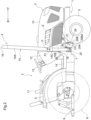
- FIGS. 1 to 3 show a tractor (corresponding to "a work vehicle” according to the present invention).
- the tractor includes a vehicle body 1, a prime mover section 2, a driving section 3, and a ROPS (Roll-Over Protective Structure) 4.
- ROPS Roll-Over Protective Structure
- the vehicle body 1 includes left and right front wheels 5, left and right rear wheels 6, and a body frame 7.
- the body frame 7 is supported by the front wheels 5 and the rear wheels 6.
- the front wheels 5 are steerable and drivable.
- the rear wheels 6 are not steerable but are drivable.
- the left rear wheel 6 is covered by a left fender 8.
- the right rear wheel 6 is covered by a right fender 8.
- the tractor is switchable between a two-wheel driven state in which only the rear wheels 6 are driven and a four-wheel driven state in which the front wheels 5 and the rear wheels 6 are driven.
- the tractor includes a link mechanism 9, to which a work device (not shown) is coupled, in a rear portion of the body frame 7.
- the prime mover section 2 is in a front portion of the vehicle body 1.
- the prime mover section 2 includes an engine E and a hood 10.
- the engine E is mounted on the front portion of the vehicle body 1.
- the hood 10 houses the engine E.
- the hood 10 is openable and closable by swinging about a rear fulcrum.
- the driving section 3 is on the rear side of the prime mover section 2.
- the driving section 3 includes a driver's seat 11, a front panel 12, a steering wheel 13, and a step 14.
- the driver's seat 11 is on the rear side with respect to the hood 10.
- the front panel 12 is continuous from a rear end portion of the hood 10 in front of the driver's seat 11.
- the steering wheel 13 is provided on the front panel 12.
- the steering wheel 13 is for steering the vehicle body 1 (the front wheels 5).
- the step 14 is under the driver's seat 11. That is to say, the step 14 extends below the driver's seat 11 on the front side thereof.
- the step 14 constitutes a floor portion of the driving section 3.
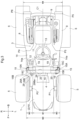
- W1 indicates a lateral width of the hood 10
- W2 indicates a lateral width of the step 14.
- the step 14 is wider than the lateral width W1 of the hood 10 in the left-right direction of the vehicle body 1.
- the step 14 includes left and right edge portions 14a, and the distance between the left and right edge portions 14a in the left-right direction of the vehicle body 1 increases rearward.
- the ROPS 4 spans a rear portion of the hood 10 in the left-right direction of the vehicle body 1.
- the ROPS 4 includes left and right columns 15 and a beam 16.
- the left column 15 is on the left side of the vehicle body 1 between a front end of the hood 10 and a front end of the driver's seat 11. In the present embodiment, the left column 15 is on the left side of the rear portion of the hood 10.
- the right column 15 is on the right side of the vehicle body 1 between the front end of the hood 10 and the front end of the driver's seat 11. In the present embodiment, the right column 15 is on the right side of the rear portion of the hood 10.
- Upper end portions of the left and right columns 15 are coupled by the beam 16.
- Each of the columns 15 includes an upper column portion 15A, a lower column portion 15B, and a support portion 15C.
- the upper column portion 15A and the lower column portion 15B are constituted by hollow members (pipe members) having substantially rectangular cross sections.
- a lower end portion of the lower column portion 15B is open downward.
- the support portion 15C is provided at an upper end portion of the lower column portion 15B.
- the upper column portion 15A is supported by the support portion 15C in such a manner as to be swingable about a swing axis X1 extending in the left-right direction of the vehicle body 1.
- the beam 16 extends from the upper end portion of the left column 15 to the upper end portion of the right column 15.
- the beam 16 is constituted by a hollow member (pipe member) having a substantially rectangular cross section.
- the left and right upper column portions 15A and the beam 16 are formed as a single piece to constitute a ROPS body.
- the position of the ROPS body can be changed between a use position at which the ROPS body extends upward from the swing axis X1 and a housed position at which the ROPS body extends forward from the swing axis X1.
- the ROPS body can be fixed to the use position and the housed position with left and right pins 17.
- the tractor includes a damper 18 that biases the ROPS body so as to swing upward about the swing axis X1.
- P1 indicates the leftmost end of the hood 10 (corresponding to "a laterally outermost end of the hood” according to the present invention)
- P2 indicates the rightmost end of the hood 10 (corresponding to "a laterally outermost end of the hood” according to the present invention)
- P3 indicates the leftmost end of the step 14 (the left edge portion 14a) (corresponding to "a laterally outermost end of the step” according to the present invention)
- P4 indicates the rightmost end of the step 14 (the right edge portion 14a) (corresponding to "a laterally outermost end of the step” according to the present invention)
- P5 indicates the leftmost end of the left fender 8
- P6 indicates the rightmost end of the right fender 8
- W3 indicates a range from the leftmost end P1 of the hood 10 to the leftmost end P3 of the step 14 in the left-right direction of the vehicle body 1
- W3 indicates a range from the rightmost end P2 of the hood 10 to the rightmost end P4 of the step
- the lateral width W1 of the hood 10 is the range from the leftmost end P1 of the hood 10 to the rightmost end P2 of the hood 10 in the left-right direction of the vehicle body 1.
- the lateral width W2 of the step 14 is the range from the leftmost end P3 of the step 14 to the rightmost end P4 of the step 14 in the left-right direction of the vehicle body 1.
- the ROPS 4 is within the range W4 and within the lateral width W2 of the step 14.
- the left column 15 is within the left range W3. That is to say, the left column 15 is located on the left side of the rear portion of the hood 10 between the left front wheel 5 and the step 14 in the front-rear direction of the vehicle body 1.
- the right column 15 is within the right range W3. That is to say, the right column 15 is located on the right side of the rear portion of the hood 10 between the right front wheel 5 and the step 14 in the front-rear direction of the vehicle body 1.
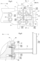
- the tractor includes a left lower support member 19 that supports a lower end portion of the left column 15.
- the tractor also includes a right lower support member 19 that supports a lower end portion of the right column 15.
- the lower support members 19 are constituted by hollow members (pipe members) having substantially rectangular cross sections.
- the left lower support member 19 extends from the lower end portion of the left lower column portion 15B toward a vehicle body center C1 in the left-right direction of the vehicle body 1.
- Aleft end portion of the left lower support member 19 is coupled (in this embodiment, welded) to the lower end portion of the left lower column portion 15B from the right side.
- a lower end of the left lower column portion 15B is below a lower surface of the left lower support member 19.
- the right lower support member 19 extends from the lower end portion of the right lower column portion 15B toward the vehicle body center C1 in the left-right direction of the vehicle body 1.
- a right end portion of the right lower support member 19 is coupled (in this embodiment, welded) to the lower end portion of the right lower column portion 15B from the left side.
- a lower end of the right lower column portion 15B is below a lower surface of the right lower support member 19.
- the tractor includes a left outer bracket 20 (corresponding to "a bracket” according to the present invention) coupled (in this embodiment, welded) to a right end portion of the left lower support member 19.
- the tractor also includes a right outer bracket 20 coupled (in this embodiment, welded) to a left end portion of the right lower support member 19.
- the tractor includes a left inner bracket 21 between the left outer bracket 20 and a left side portion of the body frame 7.
- the tractor also includes a right inner bracket 21 between the right outer bracket 20 and a right side portion of the body frame 7.
- the left outer bracket 20 and the right outer bracket 20 have similar configurations, and therefore, the following mainly describes the left outer bracket 20 out of the left and right outer brackets 20.
- the outer bracket 20 is fixed to the body frame 7 with a plurality of (in this embodiment, six) bolts 22 (corresponding to "fixing members" according to the present invention) together with the inner bracket 21.
- the inner bracket 21 is fixed to the body frame 7 with the six bolts 22 together with the outer bracket 20 and also fixed to the body frame 7 with a plurality of (in this embodiment, two) bolts 23 separately from the outer bracket 20.
- the bolts 22 include a bolt 22A (corresponding to "a third fixing member” according to the present invention), a bolt 22B (corresponding to “a third fixing member” according to the present invention), a bolt 22C (corresponding to "a fourth fixing member” according to the present invention), a bolt 22D (corresponding to "a fourth fixing member” according to the present invention), a bolt 22E (corresponding to "a first fixing member” according to the present invention), and a bolt 22F (corresponding to "a second fixing member” according to the present invention).
- the bolts 22E and 22F have diameters smaller than diameters of the bolts 22A, 22B, 22C, and 22D.
- the bolts 22A and 22B are at the same position in the front-rear direction of the vehicle body 1.
- the bolts 22C and 22D are at the same position in the front-rear direction of the vehicle body 1.
- the bolts 22E and 22F are at the same position in the front-rear direction of the vehicle body 1.
- L1 indicates a straight line passing through the center of the bolt 22A and the center of the bolt 22B
- L2 indicates a straight line passing through the center of the bolt 22C and the center of the bolt 22D
- L3 indicates a straight line passing through the center of the bolt 22E and the center of the bolt 22F
- C2 indicates a first fixing center (corresponding to "a fixing center” according to the present invention) that is a center between the straight lines L1 and L2 in the front-rear direction of the vehicle body 1.
- the first fixing center C2 is a center between the front bolts 22A and 22B and the rear bolts 22C and 22D in the front-rear direction of the vehicle body 1.
- the bolts 22A, 22C, and 22E are above the lower support member 19.
- the bolts 22B, 22D, and 22F are below the lower support member 19.
- the bolts 22A and 22C are at the same position in the up-down direction.
- the bolts 22B and 22D are at the same position in the up-down direction.
- L4 indicates a straight line passing through the center of the bolt 22A and the center of the bolt 22C
- L5 indicates a straight line passing through the center of the bolt 22B and the center of the bolt 22D
- C3 indicates a second fixing center that is a center between the straight lines L4 and L5 in the up-down direction.
- the second fixing center C3 is a center between the upper bolts 22A and 22C and the lower bolts 22B and 22D in the up-down direction.
- the lower support member 19 is on the rear side with respect to the first fixing center C2. That is to say, the lower support member 19 has a center shifted to the rear side with respect to the first fixing center C2.
- C4 indicates a cross-sectional center of the lower support member 19.
- the cross-sectional center C4 is the center of the lower support member 19 in the front-rear direction of the vehicle body 1 and in the up-down direction.
- the cross-sectional center C4 is located at the second fixing center C3 on the rear side with respect to the first fixing center C2.
- the tractor includes a second reinforcing member 25 coupled to the lower support member 19 and the outer bracket 20 and extending from the lower support member 19 toward the bolt 22F (in this embodiment, downward) in the up-down direction.
- the second reinforcing member 25 is constituted by a plate-shaped member.
- the second reinforcing member 25 is coupled (in this embodiment, welded) to a rear surface of the lower support member 19 and the laterally outer surface of the outer bracket 20.
- the tractor includes a third reinforcing member 26 coupled to the lower support member 19 and the outer bracket 20 and disposed on one side (in this embodiment, the front side) with respect to the lower support member 19 in the front-rear direction of the vehicle body 1.
- the third reinforcing member 26 is constituted by a plate-shaped member.
- the third reinforcing member 26 is also coupled to the lower column portion 15B. That is to say, the second reinforcing member 25 is coupled to the lower support member 19, the outer bracket 20, and the lower column portion 15B.
- the third reinforcing member 26 is coupled (in this embodiment, welded) to a front surface of the lower support member 19, the laterally outer surface of the outer bracket 20, and a front surface of the lower end portion of the lower column portion 15B.
- the third reinforcing member 26 is located at the first fixing center C2.
- the third reinforcing member 26 slopes downward toward the vehicle body center C 1 in the left-right direction of the vehicle body 1.
- the bolts 22A and 22B are located on the side (in this embodiment, the front side) opposite to the lower support member 19 with respect to the third reinforcing member 26 in the front-rear direction of the vehicle body 1.
- the bolts 22C and 22D are located on the lower support member 19 side (in this embodiment, the rear side) with respect to the third reinforcing member 26 in the front-rear direction of the vehicle body 1.
- the third reinforcing member 26 is between the bolts 22A and 22B and the bolts 22C and 22D in the front-rear direction of the vehicle body 1. Specifically, the third reinforcing member 26 is located at the first fixing center C2.
- the tractor includes a fourth reinforcing member 27 coupled to the outer bracket 20 and the third reinforcing member 26 and extending from the third reinforcing member 26 toward the bolts 22A and 22B (in this embodiment, forward) in the front-rear direction of the vehicle body 1.
- the fourth reinforcing member 27 is constituted by a plate-shaped member.
- the fourth reinforcing member 27 is coupled (in this embodiment, welded) to a front surface of the third reinforcing member 26 and the laterally outer surface of the outer bracket 20.
- the fourth reinforcing member 27 is between the bolt 22A and the bolt 22B in the up-down direction. Specifically, the fourth reinforcing member 27 is located at the second fixing center C3.
- the damper 18 extends from the left upper column portion 15A to the left third reinforcing member 26.
- An upper end portion of the damper 18 is supported by the left upper column portion 15A via a first stay 31.
- a lower end portion of the damper 18 is supported by the left third reinforcing member 26 via a second stay 32 and a third stay 33.
- the second stay 32 and the third stay 33 are fixed with two front and rear bolts 34.
- the tractor includes a fuel filter 28 for the engine E (corresponding to "a device for the engine” according to the present invention) on one side (in this embodiment, the front side) with respect to the left lower support member 19 in the front-rear direction of the vehicle body 1.
- the fuel filter 28 is an oil-water separating fuel filter. Separated water is discharged downward from a bottom portion of the fuel filter 28.
- the fuel filter 28 is supported by the engine E via a stay 35.
- the center of the left lower support member 19 is shifted to the side (in this embodiment, the rear side) opposite to the fuel filter 28 with respect to the first fixing center C2 in the front-rear direction of the vehicle body 1.
- the fuel filter 28 is covered by a cover 29.
- the cover 29 is supported by the right third reinforcing member 26.
- the cover 29 is fixed to the right third reinforcing member 26 with bolts 30.
- the cover 29 includes a lateral face portion 29A covering the fuel filter 28 from the right side and a front face portion 29B covering the fuel filter 28 from the front side.
- the front face portion 29B extends rearward while extending rightward and inclines forward. This configuration keeps the front face portion 29B from interfering with the right front wheel 5 when the right front wheel 5 is steered.
- a substantially arc-shaped notch 29Ba is formed in a lower edge portion of the front face portion 29B. This configuration keeps the lower edge portion of the front face portion 29B from being hit by water separated and discharged from the bottom portion of the fuel filter 28.
- the present invention is applicable to multipurpose vehicles (utility vehicles) as well as tractors.
Landscapes
- Engineering & Computer Science (AREA)
- Mechanical Engineering (AREA)
- Chemical & Material Sciences (AREA)
- Combustion & Propulsion (AREA)
- Transportation (AREA)
- Body Structure For Vehicles (AREA)
Applications Claiming Priority (2)
| Application Number | Priority Date | Filing Date | Title |
|---|---|---|---|
| JP2021179693A JP7539360B2 (ja) | 2021-11-02 | 2021-11-02 | 作業車 |
| PCT/JP2022/011688 WO2023079772A1 (ja) | 2021-11-02 | 2022-03-15 | 作業車 |
Publications (2)
| Publication Number | Publication Date |
|---|---|
| EP4428016A1 true EP4428016A1 (de) | 2024-09-11 |
| EP4428016A4 EP4428016A4 (de) | 2025-07-30 |
Family
ID=86241059
Family Applications (1)
| Application Number | Title | Priority Date | Filing Date |
|---|---|---|---|
| EP22889598.3A Pending EP4428016A4 (de) | 2021-11-02 | 2022-03-15 | Arbeitsfahrzeug |
Country Status (4)
| Country | Link |
|---|---|
| US (1) | US12337780B2 (de) |
| EP (1) | EP4428016A4 (de) |
| JP (1) | JP7539360B2 (de) |
| WO (1) | WO2023079772A1 (de) |
Family Cites Families (10)
| Publication number | Priority date | Publication date | Assignee | Title |
|---|---|---|---|---|
| GB1182282A (en) * | 1967-03-28 | 1970-02-25 | Massey Ferguson Perkins Ltd | Improvements in Safety Cabs for Tractors. |
| DE602004015058D1 (de) * | 2004-01-16 | 2008-08-28 | Same Deutz Fahr Group Spa | Gefederte Rollsicherung |
| JP2007247342A (ja) | 2006-03-17 | 2007-09-27 | Kubota Corp | フロントローダ支持装置 |
| JP2009173240A (ja) | 2008-01-28 | 2009-08-06 | Iseki & Co Ltd | 作業車両のロプス |
| JP2011184008A (ja) | 2010-03-11 | 2011-09-22 | Mitsubishi Agricultural Machinery Co Ltd | 作業用走行車における転倒保護フレームの取付構造 |
| US8424911B2 (en) * | 2011-08-26 | 2013-04-23 | Deere & Company | Folding rollover protection system with vibration dampeners |
| JP6858694B2 (ja) * | 2017-12-18 | 2021-04-14 | 株式会社クボタ | トラクタ |
| CN110786148B (zh) * | 2019-10-09 | 2021-04-27 | 江苏科技大学 | 一种吸能型坐骑式割草机翻车保护结构 |
| JP7591984B2 (ja) * | 2021-06-28 | 2024-11-29 | 株式会社クボタ | 作業車両 |
| US20240300584A1 (en) * | 2023-03-09 | 2024-09-12 | Kubota Corporation | Vehicle roof including solar panel |
-
2021
- 2021-11-02 JP JP2021179693A patent/JP7539360B2/ja active Active
-
2022
- 2022-03-15 EP EP22889598.3A patent/EP4428016A4/de active Pending
- 2022-03-15 WO PCT/JP2022/011688 patent/WO2023079772A1/ja not_active Ceased
-
2024
- 2024-04-29 US US18/648,860 patent/US12337780B2/en active Active
Also Published As
| Publication number | Publication date |
|---|---|
| WO2023079772A1 (ja) | 2023-05-11 |
| JP7539360B2 (ja) | 2024-08-23 |
| JP2023068514A (ja) | 2023-05-17 |
| US20240294134A1 (en) | 2024-09-05 |
| EP4428016A4 (de) | 2025-07-30 |
| US12337780B2 (en) | 2025-06-24 |
Similar Documents
| Publication | Publication Date | Title |
|---|---|---|
| US6460907B2 (en) | Straddle type four-wheeled all-terrain vehicle and front guard for the same | |
| CN110920752B (zh) | 悬架副车架结构 | |
| EP0285131B1 (de) | Ausbildung des hinteren Unterbodens eines Kraftfahrzeugs | |
| US9925866B2 (en) | Work vehicle | |
| JPS6311487A (ja) | 走行車輌の枠組構造 | |
| US20190359111A1 (en) | Work Vehicle | |
| EP1867558B1 (de) | Rahmenstruktur für arbeitsfahrzeug | |
| WO2009034372A1 (en) | Armoured vehicle | |
| US11117463B2 (en) | Utility vehicle | |
| EP4428016A1 (de) | Arbeitsfahrzeug | |
| JP5491945B2 (ja) | トラクタ | |
| US11376910B1 (en) | Suspension structure of utility vehicle | |
| US4692086A (en) | Load handling vehicle | |
| JPH07304406A (ja) | 4輪車用フロントキャリーバー | |
| JP6980604B2 (ja) | 作業車 | |
| JP4542456B2 (ja) | トラクタ | |
| JP7803231B2 (ja) | 作業車両 | |
| JP3366570B2 (ja) | 作業車の後部フェンダ支持構造 | |
| JP3504580B2 (ja) | 騎乗型四輪不整地走行車 | |
| JP3506998B2 (ja) | 騎乗型四輪不整地走行車のフロントガード | |
| JP2004074939A (ja) | トラクタのフレーム構造 | |
| US12485976B2 (en) | Work vehicle | |
| JP2003252236A (ja) | トラクタのフレーム構造 | |
| JP7817145B2 (ja) | 作業車 | |
| JP6790037B2 (ja) | 車両のフレーム構造 |
Legal Events
| Date | Code | Title | Description |
|---|---|---|---|
| STAA | Information on the status of an ep patent application or granted ep patent |
Free format text: STATUS: THE INTERNATIONAL PUBLICATION HAS BEEN MADE |
|
| PUAI | Public reference made under article 153(3) epc to a published international application that has entered the european phase |
Free format text: ORIGINAL CODE: 0009012 |
|
| STAA | Information on the status of an ep patent application or granted ep patent |
Free format text: STATUS: REQUEST FOR EXAMINATION WAS MADE |
|
| 17P | Request for examination filed |
Effective date: 20240425 |
|
| AK | Designated contracting states |
Kind code of ref document: A1 Designated state(s): AL AT BE BG CH CY CZ DE DK EE ES FI FR GB GR HR HU IE IS IT LI LT LU LV MC MK MT NL NO PL PT RO RS SE SI SK SM TR |
|
| DAV | Request for validation of the european patent (deleted) | ||
| DAX | Request for extension of the european patent (deleted) | ||
| A4 | Supplementary search report drawn up and despatched |
Effective date: 20250702 |
|
| RIC1 | Information provided on ipc code assigned before grant |
Ipc: B62D 49/00 20060101AFI20250626BHEP Ipc: B60R 21/13 20060101ALI20250626BHEP |