EP4426573B1 - Verstärkungsband für einen formkörper aus einer spritzfähigen formmasse sowie formkörper mit einem derartigen verstärkungsband - Google Patents
Verstärkungsband für einen formkörper aus einer spritzfähigen formmasse sowie formkörper mit einem derartigen verstärkungsband Download PDFInfo
- Publication number
- EP4426573B1 EP4426573B1 EP23706532.1A EP23706532A EP4426573B1 EP 4426573 B1 EP4426573 B1 EP 4426573B1 EP 23706532 A EP23706532 A EP 23706532A EP 4426573 B1 EP4426573 B1 EP 4426573B1
- Authority
- EP
- European Patent Office
- Prior art keywords
- edge
- reinforcing strip
- strip
- magnesium alloy
- slits
- Prior art date
- Legal status (The legal status is an assumption and is not a legal conclusion. Google has not performed a legal analysis and makes no representation as to the accuracy of the status listed.)
- Active
Links
Images


Classifications
-
- F—MECHANICAL ENGINEERING; LIGHTING; HEATING; WEAPONS; BLASTING
- F16—ENGINEERING ELEMENTS AND UNITS; GENERAL MEASURES FOR PRODUCING AND MAINTAINING EFFECTIVE FUNCTIONING OF MACHINES OR INSTALLATIONS; THERMAL INSULATION IN GENERAL
- F16J—PISTONS; CYLINDERS; SEALINGS
- F16J15/00—Sealings
- F16J15/02—Sealings between relatively-stationary surfaces
- F16J15/06—Sealings between relatively-stationary surfaces with solid packing compressed between sealing surfaces
- F16J15/10—Sealings between relatively-stationary surfaces with solid packing compressed between sealing surfaces with non-metallic packing
- F16J15/12—Sealings between relatively-stationary surfaces with solid packing compressed between sealing surfaces with non-metallic packing with metal reinforcement or covering
- F16J15/121—Sealings between relatively-stationary surfaces with solid packing compressed between sealing surfaces with non-metallic packing with metal reinforcement or covering with metal reinforcement
-
- B—PERFORMING OPERATIONS; TRANSPORTING
- B29—WORKING OF PLASTICS; WORKING OF SUBSTANCES IN A PLASTIC STATE IN GENERAL
- B29C—SHAPING OR JOINING OF PLASTICS; SHAPING OF MATERIAL IN A PLASTIC STATE, NOT OTHERWISE PROVIDED FOR; AFTER-TREATMENT OF THE SHAPED PRODUCTS, e.g. REPAIRING
- B29C48/00—Extrusion moulding, i.e. expressing the moulding material through a die or nozzle which imparts the desired form; Apparatus therefor
- B29C48/03—Extrusion moulding, i.e. expressing the moulding material through a die or nozzle which imparts the desired form; Apparatus therefor characterised by the shape of the extruded material at extrusion
- B29C48/12—Articles with an irregular circumference when viewed in cross-section, e.g. window profiles
-
- B—PERFORMING OPERATIONS; TRANSPORTING
- B29—WORKING OF PLASTICS; WORKING OF SUBSTANCES IN A PLASTIC STATE IN GENERAL
- B29C—SHAPING OR JOINING OF PLASTICS; SHAPING OF MATERIAL IN A PLASTIC STATE, NOT OTHERWISE PROVIDED FOR; AFTER-TREATMENT OF THE SHAPED PRODUCTS, e.g. REPAIRING
- B29C48/00—Extrusion moulding, i.e. expressing the moulding material through a die or nozzle which imparts the desired form; Apparatus therefor
- B29C48/15—Extrusion moulding, i.e. expressing the moulding material through a die or nozzle which imparts the desired form; Apparatus therefor incorporating preformed parts or layers, e.g. extrusion moulding around inserts
- B29C48/154—Coating solid articles, i.e. non-hollow articles
-
- B—PERFORMING OPERATIONS; TRANSPORTING
- B29—WORKING OF PLASTICS; WORKING OF SUBSTANCES IN A PLASTIC STATE IN GENERAL
- B29C—SHAPING OR JOINING OF PLASTICS; SHAPING OF MATERIAL IN A PLASTIC STATE, NOT OTHERWISE PROVIDED FOR; AFTER-TREATMENT OF THE SHAPED PRODUCTS, e.g. REPAIRING
- B29C48/00—Extrusion moulding, i.e. expressing the moulding material through a die or nozzle which imparts the desired form; Apparatus therefor
- B29C48/25—Component parts, details or accessories; Auxiliary operations
- B29C48/285—Feeding the extrusion material to the extruder
- B29C48/288—Feeding the extrusion material to the extruder in solid form, e.g. powder or granules
- B29C48/2883—Feeding the extrusion material to the extruder in solid form, e.g. powder or granules of preformed parts, e.g. inserts, retaining their shape during the extrusion process
-
- B—PERFORMING OPERATIONS; TRANSPORTING
- B60—VEHICLES IN GENERAL
- B60J—WINDOWS, WINDSCREENS, NON-FIXED ROOFS, DOORS, OR SIMILAR DEVICES FOR VEHICLES; REMOVABLE EXTERNAL PROTECTIVE COVERINGS SPECIALLY ADAPTED FOR VEHICLES
- B60J10/00—Sealing arrangements
- B60J10/15—Sealing arrangements characterised by the material
- B60J10/18—Sealing arrangements characterised by the material provided with reinforcements or inserts
-
- C—CHEMISTRY; METALLURGY
- C22—METALLURGY; FERROUS OR NON-FERROUS ALLOYS; TREATMENT OF ALLOYS OR NON-FERROUS METALS
- C22C—ALLOYS
- C22C21/00—Alloys based on aluminium
- C22C21/06—Alloys based on aluminium with magnesium as the next major constituent
-
- F—MECHANICAL ENGINEERING; LIGHTING; HEATING; WEAPONS; BLASTING
- F16—ENGINEERING ELEMENTS AND UNITS; GENERAL MEASURES FOR PRODUCING AND MAINTAINING EFFECTIVE FUNCTIONING OF MACHINES OR INSTALLATIONS; THERMAL INSULATION IN GENERAL
- F16J—PISTONS; CYLINDERS; SEALINGS
- F16J15/00—Sealings
- F16J15/02—Sealings between relatively-stationary surfaces
- F16J15/021—Sealings between relatively-stationary surfaces with elastic packing
- F16J15/022—Sealings between relatively-stationary surfaces with elastic packing characterised by structure or material
- F16J15/024—Sealings between relatively-stationary surfaces with elastic packing characterised by structure or material the packing being locally weakened in order to increase elasticity
- F16J15/025—Sealings between relatively-stationary surfaces with elastic packing characterised by structure or material the packing being locally weakened in order to increase elasticity and with at least one flexible lip
-
- B—PERFORMING OPERATIONS; TRANSPORTING
- B29—WORKING OF PLASTICS; WORKING OF SUBSTANCES IN A PLASTIC STATE IN GENERAL
- B29K—INDEXING SCHEME ASSOCIATED WITH SUBCLASSES B29B, B29C OR B29D, RELATING TO MOULDING MATERIALS OR TO MATERIALS FOR MOULDS, REINFORCEMENTS, FILLERS OR PREFORMED PARTS, e.g. INSERTS
- B29K2021/00—Use of unspecified rubbers as moulding material
-
- B—PERFORMING OPERATIONS; TRANSPORTING
- B29—WORKING OF PLASTICS; WORKING OF SUBSTANCES IN A PLASTIC STATE IN GENERAL
- B29K—INDEXING SCHEME ASSOCIATED WITH SUBCLASSES B29B, B29C OR B29D, RELATING TO MOULDING MATERIALS OR TO MATERIALS FOR MOULDS, REINFORCEMENTS, FILLERS OR PREFORMED PARTS, e.g. INSERTS
- B29K2705/00—Use of metals, their alloys or their compounds, for preformed parts, e.g. for inserts
- B29K2705/02—Aluminium
Definitions
- the present invention relates to a reinforcement band for a molded body made of an injection-moldable molding compound, comprising a band-shaped base body made of an aluminum-magnesium alloy according to the alloy group EN AW-5xxx. Furthermore, the invention relates to a molded body with such a reinforcement band.
- Reinforcing strips of the type mentioned above are used to reinforce a molded body made of an injection-moldable molding compound, such as a sealing strip made of elastomeric material. Such sealing strips are used to seal openings in a vehicle, such as a door opening, a window opening, or a tailgate opening.
- the opening is provided with a flange surrounding the opening, onto which the sealing strip is placed or clamped.
- the reinforcement strip is formed into a U-shaped profile. To prevent it from being pulled off the flange, the reinforcement strip must have a high clamping force.
- the reinforcement strip formed into a U-profile into a sealing strip is coated with an injection-moldable molding compound, such as plastic and/or elastomer, in a subsequent extrusion process.
- an injection-moldable molding compound such as plastic and/or elastomer
- the reinforcement strips are provided with slits, which also reduce the weight of the reinforcement strips.
- the slits are cut into the reinforcement strips in a continuous manufacturing process by rotary cutting or punching. strip and then expanded by stretching, such as rolling.
- the reinforcement tape Since high longitudinal forces act on the reinforcement tape during extrusion, the reinforcement tape must have high strength characteristics in addition to the high clamping force.
- DE 20 201 104 735 U1 a metal strip as an insert for decorative or sealing strips or as edge protection, which is provided in particular with cut and/or punched openings, wherein the metal strip consists of micro-alloyed steel or multi-phase steel.
- HURD TIM J ET AL "Al-Mg sheet for automotive and architectural applications. EN-AW 5xxx processing, microstructure, simulation and property control", January 1, 2006 (2006-01-01), VIRTUAL FABRICATION OF ALUMINUM PRODUCTS, WILEY-VCH, OE, PAGE(S) 37-50, XP009180649, ISBN: 978-3-527-31363-1 the use of aluminum-magnesium strips for automotive and/or architectural applications.
- the invention is based on the object of creating a reinforcing band and a shaped body which have a reduced use of material and a low weight.
- a reinforcing strip for a molded body made of an injection-moldable molding compound comprises a strip-shaped base body made of an aluminum-magnesium alloy according to alloy group EN AW-5xxx, wherein the aluminum-magnesium alloy of the strip-shaped base body has a yield strength and/or a tensile strength that is higher and/or lower than the yield strength and/or the tensile strength of a corresponding aluminum-magnesium alloy according to alloy group EN AW-5xxx.
- the strength of the reinforcement band can be increased. This allows the band thickness and thus the material usage to be reduced, while simultaneously reducing the weight of the reinforcement band.
- the reinforcement tape can also be called scaffolding tape, insert tape or carrier tape.
- the molded body can be a sealing strip for a vehicle, a decorative strip, or a strip for edge protection.
- the injection-moldable molding compound can be a plastic and/or an elastomeric material.
- the EN AW-5xxx alloy group refers to a standardized aluminum-magnesium alloy grade (AlMg alloy) whose main alloying component is magnesium.
- AlMg alloy aluminum-magnesium alloy grade
- the chemical compositions and standardized designations of the alloys in the EN AW-5xxx alloy group are described in DIN EN 573-3.
- the chemical compositions and standardized designations of the alloys in the ENAW-5xxx alloy group are described in DIN EN 573-3:2022-09 (Aluminum and aluminum alloys - Chemical composition and shape of semi-finished products - Part 3: Chemical composition and product forms; German version EN 573-3:2019+A1:2022).
- the magnesium content of the aluminum-magnesium alloy according to alloy group EN AW-5xxx can range from approximately 0.2% to approximately 5.6%.
- the alloy may also contain other components, such as silicon (Si), iron (Fe), copper (Cu), manganese (Mn), magnesium (Mg), chromium (Cr), titanium (Ti), and/or zinc (Zn).
- a reinforcing strip for a molded body made of an injection-moldable molding compound has a strip-shaped base body made of an aluminum-magnesium alloy according to EN AW-5754, wherein the aluminum-magnesium alloy of the strip-shaped base body has a yield strength and/or a tensile strength that is higher and/or lower than the yield strength and/or the tensile strength a corresponding aluminum-magnesium alloy according to EN AW-5754.
- the yield strength and/or tensile strength of the aluminum-magnesium alloy of the strip-shaped base body is between 5% and 50% higher and/or lower than the yield strength and/or tensile strength of a corresponding aluminum-magnesium alloy according to the alloy group EN AW-5xxx.
- the yield strength and/or tensile strength of the aluminum-magnesium alloy of the strip-shaped base body can be up to approximately 40 N/ mm2 higher and/or lower than the yield strength and/or tensile strength of a corresponding aluminum-magnesium alloy according to the alloy group EN AW-5xxx.
- the mechanical properties of the alloy group ENAW-5xxx are described in DIN EN 485-2 and in DIN EN 1396.
- the mechanical properties of the alloy group ENAW-5xxx are described in DIN EN 485-2: 2018-12 (Aluminium and aluminium alloys - Strip, sheet and plate - Part 2: Mechanical properties; German version EN 485-2: 2016+A12018) and in DIN EN 1396: 2015-06 (Aluminium and aluminium alloys - Coil-coated sheet and strip for general applications - Specifications; German version EN 1396: 2015).
- alloys of the ENAW-5xxx alloy group are assigned to material tempers described in DIN EN 515, particularly in DIN EN 515: 2017-05 (Aluminium and aluminum alloys - Semi-finished products - Designations of material tempers; German version EN 515:2017).
- the following table lists the most common material tempers used in European standards.
- Hxy The material conditions listed in the DIN EN 515 table are referred to below as Hxy, where x stands for the first number or first two numbers and y for the second number or third number.
- the yield strength and/or the tensile strength of an aluminum-magnesium alloy according to the alloy group EN AW-5xxx in a Hxy state can be increased and/or reduced compared to the corresponding aluminum-magnesium alloy according to the alloy group EN AW-5xxx in the Hxy state, in particular in the same Hxy state, by treating the aluminum-magnesium alloy according to the alloy group EN AW-5xxx, for example by rolling, annealing and/or heat treating.
- the aluminum-magnesium alloy of the base body in the Hxy state has a higher tensile strength than a corresponding aluminum-magnesium alloy according to the EN AW-5xxx alloy group in the Hxy state, particularly in the same Hxy state.
- This makes it possible to design the reinforcement strip more stable than a reinforcement strip made of an aluminum-magnesium alloy according to the EN AW-5xxx alloy group in the Hxy state. This allows the strip thickness and the weight of the reinforcement strip to be reduced.
- a treated aluminum-magnesium alloy EN AW-5754 in the H22 material temper and with a material thickness of 0.8 mm has a tensile strength Rm of 271 to 310 MPa, a yield strength Rp0.2 of at least 130 MPa, and an elongation at break A50 of at least 8%.
- an aluminum-magnesium alloy EN AW-5754 in the H22 material temper and with a material thickness of 0.8 mm according to EN 485-2 has a tensile strength Rm of 220 to 270 MPa.
- a treated aluminum-magnesium alloy EN AW-5454 in the material temper 0/H111 and with a material thickness of 0.80 mm has a tensile strength Rm of 276 to 305 MPa, a yield strength Rp0.2 of at least 85 MPa, and an elongation at break A50 of at least 13%.
- an aluminum-magnesium alloy EN AW-5454 in the material temper 0/H111 and with a material thickness of 0.8 mm according to EN 485-2 has a tensile strength Rm of 215 to 275 MPa.
- the tensile strength of the aluminum-magnesium alloy in the Hxy state of the reinforcing strip according to the invention is up to 40 N/mm 2 more than a corresponding aluminum-magnesium alloy according to the alloy group EN AW-5xxx in the Hxy state.
- the aluminum-magnesium alloy of the base body in the Hxy state has a lower yield strength than a corresponding aluminum-magnesium alloy according to the EN AW-5xxx alloy group in the Hxy state, in particular in the same Hxy state. Due to the reduced yield strength compared to a known aluminum-magnesium alloy according to the EN AW-5xxx alloy group, the reinforcing strip according to the invention can be further stretched, i.e., drawn out in length. This makes it possible to reduce the material used and the weight of the reinforcing strip.
- the yield strength of the aluminum-magnesium alloy in the Hxy state of the reinforcing strip according to the invention is up to 40 N/mm 2 less than a corresponding aluminum-magnesium alloy according to the EN AW-5xxx alloy group in the Hxy state.
- a treated aluminum-magnesium alloy EN AW-5754 in the H22 material temper and with a material thickness of 0.6 mm has a tensile strength Rm of 220 to 270 MPa, a yield strength Rp0.2 of 90 to 129 MPa, and an elongation at break A50 of at least 10%.
- an aluminum-magnesium alloy EN AW-5754 in the H22 material temper and with a material thickness of 0.6 mm according to EN 485-2 has a yield strength Rp0.2 of at least 130 MPa and an elongation at break A50 of at least 8%.
- the minimum elongation at break can be increased.
- the aluminum-magnesium alloy is rolled, annealed, or heat-treated. This increases and/or decreases the yield strength and/or tensile strength.
- the base body has a thickness between 0.46 mm and 0.84 mm, in particular between 0.5 mm and 0.8 mm, and furthermore in particular between 0.57 mm and 0.77 mm. Due to the small thickness, the reinforcement band is lightweight.
- the base body has a plurality of widened edge slots that extend inward from edge sections of the base body transversely to its longitudinal direction, and a plurality of widened inner slots that are arranged in an inner section located between the edge sections of the base body.
- the edge slots can taper inward in a wedge-shaped or pointed manner.
- the edge slots are open on the outside of the band, i.e., the edge slots do not have a fixed border at the edges of the base body.
- two edge slots are located opposite each other in pairs.
- the edge slots can be offset from each other.
- the edge slots are wedge-shaped inward.
- the inner slots are designed as openings with a fixed border. The openings can be diamond-shaped.
- the edge slots advantageously create slats that, when the reinforcement strip is formed, grip the flange of a vehicle opening and apply the clamping force.
- the slats can be positioned directly opposite each other or offset from each other.
- edge slots and/or the inner slots are introduced into the base body by rotary cutting or punching, and the edge slots and/or the inner slots are widened by subsequent stretching, such as rolling, of the base body.
- the opening width of the edge slots and/or the inner slots is between 0.5 mm and 4 mm. Furthermore, the opening width of the edge slots and/or the inner slots is between 1 mm and 3.5 mm.
- the edge slits have a length corresponding to between one third and one half of a width of the reinforcing band, and the inner slits have a length corresponding to between 1/8 and 2/3 of the width of the reinforcing band.
- the inner slots are formed from at least one first row with a first contour and at least one second row with a second contour. Furthermore, the inner slots are advantageously formed from two first rows with a first contour and a second row with a second contour.
- the edge slots can have a V-shape, with the edge slots advantageously tapering inward.
- the inner slits of the first row are longer than the inner slits of the second row.
- the edge slits can have a length corresponding to approximately 1/3 of the width of the reinforcement band.
- the inner slits of the first row can have a length corresponding to approximately 1/3 of the width of the reinforcement band, and the inner slits of the second row can have a length corresponding to approximately 1/8 of the width of the reinforcement band.
- the first contour may have an approximate teardrop shape and the second contour may have an approximate hexahedron shape.
- an inner slot of the second row is arranged alternately in the longitudinal direction of the reinforcing band between each pair of edge slots, and two opposing inner slots of the first row are arranged between each two successive pairs of edge slots.
- edge slots and the inner slots overlap transversely to the longitudinal direction, wherein the overlapping edge slots and inner slots are separated from one another by webs, wherein the webs have a width between 1 mm and 3 mm.
- two edge slits are arranged alternately opposite one another in the longitudinal direction of the reinforcing band and an inner slit is arranged offset in the longitudinal direction.
- an edge slot of a first edge section and an inner slot are arranged alternately opposite one another in the longitudinal direction of the reinforcing band, and an edge slot of a second edge section and an inner slot are arranged opposite one another in a longitudinally offset manner.
- an inner slot is arranged alternately in the longitudinal direction of the reinforcing band between two pairs of opposite edge slots and two opposite inner slots are arranged offset in the longitudinal direction.
- the thickness of the edge sections is greater than the thickness of the inner section.
- a molded body made of an injectable molding compound with a reinforcing band according to the invention is proposed.
- the molded body is made of a plastic and/or an elastomer material.
- the molded body can be produced by injection molding or extrusion.
- the reinforcement strip can first be formed, in particular bent, into a U-shaped profile, and then the reinforcement strip can be overmolded with a plastic or elastomer material.
- the reinforcement strip is formed into a V-shaped profile or a U-shaped profile.
- the U-shaped profile can be clipped or clamped onto a flange, for example, a flange of a vehicle opening, to secure the molded body.
- the molded body is a sealing strip for a vehicle.
- the sealing strip can have a sealing lip and a mounting shaft.
- the reinforcement strip formed into a V-shaped or U-shaped profile, is advantageously embedded in the mounting shaft.
- a reinforcing band 10 is shown, which is used to reinforce a Fig. 3 illustrated molded body 11.
- the molded body 11 is in the present case a sealing strip 12 for a vehicle not shown, which has a sealing lip 28 and a plug-in shaft 30.
- the reinforcing band 10 has a width B between 15 mm and 60 mm, in particular between 20 mm and 45 mm, and a thickness D between 0.46 mm and 0.84 mm, in particular between 0.5 mm and 0.8 mm, furthermore in particular between 0.57 mm and 0.77 mm.
- the reinforcing band 10 has a band-shaped base body 14 which is formed from a first edge portion 16a, a second edge portion 16b and an inner portion 18 arranged therebetween.
- Each of the edge sections 16a, 16b has a plurality of slats 17 which are interrupted by edge slots 20.
- the edge slots 20 extend inwardly from an edge 22 of the base body 14 transversely to the longitudinal direction L, with two edge slots 20 always being opposite each other.
- the edge slots 20 are wedge-shaped inwards.
- inner slots 24 are provided which are wedge-shaped on both sides. As shown in Fig. 1 As can be seen, an inner slot 24 is arranged alternately in the longitudinal direction L of the reinforcement band between each pair of edge slots 22, and two opposing inner slots 24 are arranged between each two successive pairs of edge slots 20.
- the edge slots 20 have a length L1 which corresponds approximately to one-third of the width B of the reinforcement band 10, and the inner slots 24 have a length L2 which corresponds between 1/8 and 2/3 of the width B of the reinforcement band 10.
- the edge slots 20 and the inner slots 24 are produced by rotary cutting or punching of the base body 14 and by stretching, that is, by pulling the base body 14 in the longitudinal direction L, for example by means of rolling stretches, into the Fig. 1
- the opening width of the edge slots 22 and the inner slots 24 can be between 1 mm and 4 mm.
- the slats 17 can have a width between 2.5 and 4.5 mm.
- edge slots 20 and the inner slots 24 overlap transversely to the longitudinal direction L, whereby the overlapping edge slots 20 and inner slots 24 are separated from each other by webs 25 which have a width between 1 mm and 3 mm.
- the reinforcing strip 10 is made of an aluminum-magnesium alloy according to the alloy group EN AW-5xxx.
- the magnesium content in the alloy can be between approximately 0.2% and 5.6%.
- the aluminum-magnesium alloy can contain other components, such as silicon (Si), iron (Fe), copper (Cu), manganese (Mn), magnesium (Mg), chromium (Cr), titanium (Ti), and/or zinc (Zn).
- the aluminum-magnesium alloy of the reinforcing strip is treated, for example, rolled, annealed, and/or heat-treated, to increase the strength of the reinforcing strip 10.
- the base body 14, in a Hxy state has a tensile strength that is greater than the tensile strength of a corresponding aluminum-magnesium alloy according to the alloy group EN AW-5xxx in the same Hxy state.
- the tensile strength of the aluminum-magnesium alloy of the reinforcing strip 10 in the Hxy state can be up to 40 N/mm 2 higher than the tensile strength of a corresponding aluminum-magnesium alloy according to the alloy group EN AW-5xxx in the Hxy state.
- a treated aluminum-magnesium alloy EN AW-5754 in the H22 material temper and with a material thickness of 0.8 mm has a tensile strength Rm of 271 to 310 MPa, a yield strength Rp0.2 of at least 130 MPa, and an elongation at break A50 of at least 8%.
- an aluminum-magnesium alloy EN AW-5754 in the H22 material temper and with a material thickness of 0.8 mm according to EN 485-2 has a tensile strength Rm of 220 to 270 MPa.
- a treated aluminum-magnesium alloy EN AW-5454 in the material temper 0/H111 and with a material thickness of 0.80 mm has a tensile strength Rm of 276 to 305 MPa, a yield strength Rp0.2 of at least 85 MPa, and an elongation at break A50 of at least 13%.
- an aluminum-magnesium alloy EN AW-5454 in the material temper 0/H111 and with a material thickness of 0.8 mm according to EN 485-2 has a tensile strength Rm of 215 to 275 MPa.
- the base body 14 in a state Hxy can have a yield strength that is lower than the yield strength of a corresponding aluminum-magnesium alloy according to the alloy group EN AW-5xxx in the same state Hxy.
- a treated aluminum-magnesium alloy EN AW-5754 in the H22 material temper and a material thickness of 0.6 mm has a tensile strength Rm of 220 to 270 MPa, a yield strength Rp0.2 of 90 to 129 MPa, and an elongation at break A50 of at least 10%.
- an aluminum-magnesium alloy EN AW-5754 in the H22 material temper and a material thickness of 0.6 mm according to EN 485-2 has a yield strength Rp0.2 of at least 130 MPa and an elongation at break A50 of at least 8%.
- the reinforcing band 10 can be further stretched. This minimizes material usage and reduces weight.
- the minimum value for elongation at break can be increased.
- the tensile strength and/or yield strength of an aluminum-magnesium alloy according to the alloy group EN AW-5xxx in a Hxy state can be reduced and/or increased compared to the corresponding aluminum-magnesium alloy according to the alloy group EN AW-5xxx in the same Hxy state by treating the aluminum-magnesium alloy according to the alloy group EN AW-5xxx with the Hxy state, in particular by rolling, annealing or heat-treating.
- the reinforcing band 10 is bent into a U-shaped profile 26, as shown in Fig. 3 is shown.
- the U-profile 26 is then overmolded with a plastic or elastomeric material in an extrusion process, so that a molded body 11 designed as a sealing strip 12 is created.
- a second embodiment of the reinforcing band 10 is shown, which differs from the first embodiment in that a thickness D1 of the edge portions 16a, 16b, in particular the edges 22, is greater than a thickness D2 of the inner portion 18. This prevents damage to the molded body 11.
- a third embodiment of the reinforcing band 10 is shown, which differs from the other two embodiments by the arrangement of the edge slots 20 and the inner slots 24.
- edge slots 20 are arranged alternately in pairs in the longitudinal direction L of the reinforcing band 10, opposite one another, and an inner slot 24 is introduced into the base body 14, offset in the longitudinal direction L.
- the edge slots 20 have a length L1 which corresponds approximately to one third of the width B of the reinforcing band 10, and the inner slots 24 have a length L2 which corresponds between 1/8 and 2/3 of the width B of the reinforcing band 10.
- the thickness D1 of the edge sections 16a, 16b of the reinforcing band 10 of the third embodiment is greater than the thickness D2 of the inner section 18.
- the reinforcing band 10 of the third embodiment can, like the reinforcing band 10 of the first embodiment, have a uniform thickness D transversely to the longitudinal direction L.
- the Fig. 8 The reinforcement band 10 shown is bent into a U-shaped profile 26, as shown in Fig. 10 shown, and in an extrusion process with a plastic or elastomeric material to form a sealing strip, such as the one in the Figures 4 and 7 shown.
- a fourth embodiment of the reinforcing band 10 is shown, which differs from the third embodiment in the length L1 of the edge slots and the length L2 of the inner slots.
- FIG. 8 A comparison of the Fig. 8 with Fig. 11 illustrates that in the fourth embodiment, compared to the third embodiment, the length L1 of the edge slots 20 is greater and the length L2 of the inner slots 24 is smaller.
- the edge slots 20 of the fourth embodiment have a length L1 corresponding to approximately half the width B of the reinforcing band 10, and the inner slots 24 have a length L2 corresponding to between 1/8 and 2/3 of the width B of the reinforcing band 10.
- the reinforcing band of the fourth embodiment bent into a U-shaped profile 26, has a greater height and a simultaneously smaller width compared to the U-shaped profile of the third embodiment.
- the thickness D1 of the edge sections 16a, 16b of the reinforcing band 10 of the fourth embodiment is greater than the thickness D2 of the inner section 18.
- the reinforcing band 10 of the fourth embodiment can, like the reinforcing band 10 of the first embodiment, have a thickness D that is uniform transversely to the longitudinal direction L.
- the Fig. 11 The reinforcement band 10 shown is bent into a U-shaped profile 26, as shown in Fig. 13 shown, and overmolded in an extrusion process with a plastic or elastomeric material to form a sealing strip, as shown in the Figures 4 and 7 shown.
- a fifth embodiment of the reinforcing band 10 is shown, which differs from the other embodiments by the arrangement of the edge slots 20 and the inner slots 24.
- both the edge slots 20 and the inner slots 24 are arranged offset from one another in the longitudinal direction L.
- an edge slot 20 of a first edge section 16a and an inner slot 24 are arranged opposite one another alternately in the longitudinal direction L of the reinforcing band 10
- an edge slot 20 of a second edge section 16b and an inner slot 24 are arranged opposite one another offset in the longitudinal direction L.
- the edge slots 20 of the fifth embodiment have a length L1 corresponding to approximately 1/3 of the width B of the reinforcing band 10, and the inner slots 24 have a length L2 corresponding to between 1/8 and 2/3 of the width B of the reinforcing band 10.
- the edge sections 16a, 16b can have a thickness D1 which, as shown in the Figures 5 , 9 and 12 is greater than the thickness D2 of the inner section 18, or which, as shown in Fig. 2 is equal to the thickness D2 of the inner section 18.
- the reinforcement band 10 shown is bent into a U-shaped profile 26, as shown in the Figures 4, 6 , 10 and 13 shown, and overmolded in an extrusion process with a plastic or elastomeric material to form a sealing strip, as shown in the Figures 4 and 7 shown.
- a sixth embodiment of the reinforcing band 10 is shown, which differs from the other embodiments in the design of the edge slots 20 and the inner slots 24.
- edge slots 20 are V-shaped, in that the edge slots 20 taper inwards.
- the inner slots 24 are formed from two first rows 32 with a first contour 34 and from a second row 36 with a second contour 36, wherein the inner slots 24 of the first row 32 are longer than the inner slots 24 of the second Row 36.
- the first contour 34 has an approximate teardrop shape and the second contour 36 has an approximate hexahedron shape.
- an inner slot 24 of the second row 36 is arranged alternately in the longitudinal direction L of the reinforcing band 10 between two edge slots 22 and two opposite inner slots 24 of the first row 32 are arranged between each two successive pairs of edge slots 20.
- the edge slots 20 of the sixth embodiment have a length L1 corresponding to approximately 1/3 of the width B of the reinforcement band 10.
- the inner slots 24 of the first row 32 have a length L2 corresponding to approximately 1/3 of the width B of the reinforcement band 10, and the inner slots 24 of the second row 36 have a length L2 corresponding to approximately 1/8 of the width B of the reinforcement band 10.
- the edge sections 16a, 16b may have a thickness D1 which, as shown in the Figures 5 , 9 and 12 is greater than the thickness D2 of the inner section 18, or which, as shown in Fig. 2 is equal to the thickness D2 of the inner section 18.
- the Fig. 15 The reinforcement band 10 shown is bent into a U-shaped profile 26, as shown in the Figures 4, 6 , 10 and 13 shown, and overmolded in an extrusion process with a plastic or elastomeric material to form the Fig. 16 to produce the sealing strip 12 shown.
- the reinforcement band 10 can be further stretched, i.e., drawn out. This allows the material usage to be reduced and, at the same time, the weight of the reinforcement band 10 to be reduced.
Landscapes
- Engineering & Computer Science (AREA)
- Mechanical Engineering (AREA)
- General Engineering & Computer Science (AREA)
- Chemical & Material Sciences (AREA)
- Materials Engineering (AREA)
- Metallurgy (AREA)
- Organic Chemistry (AREA)
- Package Frames And Binding Bands (AREA)
- Body Structure For Vehicles (AREA)
- Manufacture Of Alloys Or Alloy Compounds (AREA)
Description
- Die vorliegende Erfindung betrifft ein Verstärkungsband für einen Formkörper aus einer spritzfähigen Formmasse, aufweisend einen bandförmigen Grundkörper aus einer Aluminium-Magnesium-Legierung gemäß der Legierungsgruppe EN AW-5xxx. Des Weiteren betrifft die Erfindung einen Formkörper mit einem derartigen Verstärkungsband.
- Verstärkungsbänder der eingangs genannten Art werden zur Armierung eines Formkörpers aus einer spritzfähigen Formmasse, wie beispielsweise eines Dichtungsstranges aus elastomeren Werkstoff, eingesetzt. Derartige Dichtungsstränge werden zum Abdichten von Öffnungen eines Fahrzeugs, wie beispielsweise einer Türöffnung, einer Fensteröffnung oder einer Heckklappenöffnung, verwendet.
- Zur Befestigung des Dichtungsstranges ist die Öffnung mit einem die Öffnung umlaufenden Flansch versehen, auf welchen der Dichtungsstrang aufgesteckt beziehungsweise geklemmt wird. Hierzu ist das Verstärkungsband zu einem U-Profil umgeformt. Um ein Abziehen von dem Flansch zu verhindern, ist es erforderlich, dass das Verstärkungsband eine hohe Klemmkraft aufweist.
- Bei der Weiterverarbeitung des zu einem U-Profil umgeformten Verstärkungsbandes zu einem Dichtungsstrang wird in einem anschließenden Extrusionsprozess das Verstärkungsband mit einer spritzfähigen Formmasse, wie beispielsweise Kunststoff und/oder Elastomer, ummantelt.
- Um ein Durchdringen der spritzfähigen Formmasse zu ermöglichen, werden die Verstärkungsbänder mit Schlitzen versehen, welche zudem das Gewicht der Verstärkungsbänder reduzieren. Die Schlitze werden in einem kontinuierlichen Herstellungsverfahren durch rotatives Schneiden oder Stanzen in das Verstärkungs-Deutschland
band eingebracht und durch Recken, wie beispielsweise Walzstrecken, anschließend aufgeweitet. - Da während der Extrusion hohe Kräfte in Längsrichtung auf das Verstärkungsbandes wirken, muss das Verstärkungsband neben der hohen Klemmkraft hohe Festigkeitskennwerte aufweisen.
- Um diese Anforderungen zu erfüllen, sind die aus
DE 100 33 454 A1 und
DE 10 2016 005 074 A1 bekannten Verstärkungsbänder aus Stahl. Im Zuge der steten Gewichtsreduktion im Fahrzeugbau werden zunehmend Verstärkungsbänder aus Aluminium-Magnesium-Legierungen eingesetzt. - Des Weiteren geht aus
DE 20 201 104 735 U1 ein Metallband als Einlage für Zier- oder Dichtstreifen oder als Kantenschutz hervor, welches insbesondere mit geschnittenen und/oder gestanzten Durchbrüchen versehen ist, wobei das Metallband aus mikrolegiertem Stahl oder Mehrphasenstahl besteht. - Zudem zeigt HURD TIM J ET AL: "Al-Mg sheet for automotive and architectural applications. EN-AW 5xxx processing, microstructure, simulation and property control", 1. Januar 2006 (2006-01-01), VIRTUAL FABRICATION OF ALUMINUM PRODUCTS, WILEY-VCH, OE, PAGE(S) 37-50, XP009180649, ISBN: 978-3-527-31363-1 den Einsatz von Aluminium-Magnesium-Bändern für Automobile und/oder architektonische Anwendungen.
- Der Erfindung liegt die Aufgabe zugrunde, ein Verstärkungsband und einen Formkörper zu schaffen, die einen reduzierten Materialeinsatz und ein geringes Gewicht aufweisen.
- Zur Lösung der Aufgabe wird ein Verstärkungsband mit den Merkmalen des Anspruchs 1 und ein Formkörper mit den Merkmalen des Anspruchs 14 vorgeschlagen.
- Vorteilhafte Ausgestaltungen des Verstärkungsbands und des Formkörpers sind Gegenstand der jeweils abhängigen Ansprüche.
- Gemäß einem Aspekt wird ein Verstärkungsband für einen Formkörper aus einer spritzfähigen Formmasse vorgeschlagen. Das Verstärkungsband weist einen bandförmigen Grundkörper aus einer Aluminium-Magnesium-Legierung gemäß Legierungsgruppe EN AW-5xxx auf, wobei die Aluminium-Magnesium-Legierung des bandförmigen Grundkörpers eine Streckgrenze und/oder eine Zugfestigkeit aufweist, die höher und/oder niedriger als die Streckgrenze und/oder die Zugfestigkeit einer korrespondierenden Aluminium-Magnesium-Legierung gemäß der Legierungsgruppe EN AW-5xxx ist.
- Durch die Erhöhung und/oder Reduzierung der Streckgrenze und/oder der Zugfestigkeit kann das Verstärkungsband in der Festigkeit erhöht werden. Dadurch kann die Banddicke und somit der Materialeinsatz reduziert und gleichzeitig das Gewicht des Verstärkungsbandes verringert werden.
- Das Verstärkungsband kann auch als Gerüstband, Einlegeband oder Trägerband bezeichnet werden.
- Der Formkörper kann ein Dichtungsstrang für ein Fahrzeug, ein Zierstrang oder ein Strang zum Schutz von Kanten sein. Die spritzfähige Formmasse kann ein Kunststoff und/oder ein elastomerer Werkstoff sein.
- Die Legierungsgruppe EN AW-5xxx bezieht sich auf eine genormte Aluminium-Magnesium-Legierungs-Sorte (AIMg-Legierung), deren Hauptlegierungsbestandteil Magnesium ist. Die chemischen Zusammensetzungen und die genormten Bezeichnungen der Legierungen der Legierungsgruppe EN AW-5xxx sind in der DIN EN 573-3 beschrieben. Insbesondere sind die chemischen Zusammensetzungen und die genormten Bezeichnungen der Legierungen der Legierungsgruppe ENAW-5xxx in der DIN EN 573-3:2022-09 (Aluminium und Aluminiumlegierungen - Chemische Zusammensetzung und Form von Halbzeug - Teil 3: Chemische Zusammensetzung und Erzeugnisformen; Deutsche Fassung EN 573-3: 2019+A1:2022) beschrieben. Weiterhin insbesondere sind die chemischen Zusammensetzungen und die genormten Bezeichnungen der Legierungen der Legierungsgruppe ENAW-5xxx auf Seite 13 bis 15 der DIN EN 573-3: 2022-09 beschrieben. Die Legierungsgruppe EN AW-5xxx kann auch als Serie 5xxx bezeichnet werden.
- Der Magnesiumanteil der Aluminium-Magnesium-Legierung gemäß Legierungsgruppe EN AW-5xxx kann zwischen ca. 0,2 % und ca. 5,6 % betragen. Darüber hinaus kann die Legierung noch weitere Bestandteile, wie beispielsweise Silizium (Si), Eisen (Fe), Kupfer (Cu), Mangan (Mn), Magnesium (Mg), Chrom (Cr), Titan (Ti) und/oder Zink (Zn), enthalten.
- In einer vorteilhaften Ausgestaltung wird ein Verstärkungsband für einen Formkörper aus einer spritzfähigen Formmasse vorgeschlagen. Das Verstärkungsband weist einen bandförmigen Grundkörper aus einer Aluminium-Magnesium-Legierung gemäß EN AW-5754 auf, wobei die Aluminium-Magnesium-Legierung des bandförmigen Grundkörpers eine Streckgrenze und/oder eine Zugfestigkeit aufweist, die höher und/oder niedriger als die Streckgrenze und/oder die Zugfestigkeit einer korrespondierenden Aluminium-Magnesium-Legierung gemäß EN AW-5754 ist.
- In einer vorteilhaften Ausgestaltung ist die Streckgrenze und/oder die Zugfestigkeit der Aluminium-Magnesium-Legierung des bandförmigen Grundkörpers zwischen 5% und 50% höher und/oder niedriger als die Streckgrenze und/oder die Zugfestigkeit einer korrespondierenden Aluminium-Magnesium-Legierung gemäß der Legierungsgruppe EN AW-5xxx. So kann die Streckgrenze und/oder Zugfestigkeit der Aluminium-Magnesium-Legierung des bandförmigen Grundkörpers bis zu ca. 40 N/mm2 höher und/oder niedriger als die Streckgrenze und/oder die Zugfestigkeit einer korrespondierenden Aluminium-Magnesium-Legierung gemäß der Legierungsgruppe EN AW-5xxx sein.
- Die mechanischen Eigenschaften der Legierungsgruppe ENAW-5xxx sind in DIN EN 485-2 und in DIN EN 1396 beschrieben Insbesondere sind die mechanischen Eigenschaften der Legierungsgruppe ENAW-5xxx in DIN EN 485-2: 2018-12 (Aluminium und Aluminiumlegierungen - Bänder, Bleche und Platten - Teil 2: Mechanische Eigenschaften; Deutsche Fassung EN 485-2: 2016+A12018) und in DIN EN 1396: 2015-06 (Aluminium und Aluminiumlegierungen - Bandbeschichtete Bleche und Bänder für allgemeine Anwendungen - Spezifikationen: ; Deutsche Fassung EN 1396: 2015) beschrieben. In der DIN EN 485-2 und der DIN EN 1396 erfolgt die Zuordnung zu den Legierungen der Legierungsgruppe ENAW-5xxx zu Werkstoffzuständen, die in DIN EN 515, insbesondere in DIN EN 515: 2017-05 (Aluminium und Aluminiumlegierungen - Halbzeug - Bezeichnungen der Werkstoffzustände; Deutsche Fassung EN 515:2017) beschrieben sind. In der nachfolgenden Tabelle sind die in den Europäischen Normen gebräuchlichsten Werkstoffzustände sinngemäß aufgeführt, wobei die Auflistung nicht als abschließend anzusehen ist, sondern alle in der DIN EN 515 aufgelisteten Werkstoffzustände werden in die vorliegende Erfindung mit eingeschlossen:
Zustand Bedeutung H12 Kaltverfestigt - 1/4 hart H14 Kaltverfestigt - 1/2 hart H16 Kaltverfestigt - 3/4 hart H18 Kaltverfestigt - 4/4 hart (voll durchgehärtet) H19 Kaltverfestigt - extrahart Hxx4 Gilt für dessinierte oder geprägte Bleche oder Bänder, die aus dem entsprechenden Hxx-Zustand hergestellt sind Hxx5 Kaltverfestigt - Gilt für geschweißte Rohre H111 bzw. 0/H111 Geglüht und durch anschließende Arbeitsgänge, zum Beispiel Recken oder Richten, geringfügig kaltverfestigt (weniger als H11) H112 Durch Warmumformung oder eine begrenzte Kaltumformung geringfügig kaltverfestigt. (mit festgelegten Grenzwerten der mechanischen Eigenschaften) H116 Gilt für Aluminium-Magnesium-Legierungen mit einem Magnesiumanteil >= 4 %, für die die Grenzwerte der mechanischen Eigenschaften und die Beständigkeit gegen Schichtkorrosion festgelegt sind. H22 Kaltverfestigt und rückgeglüht - 1/4 hart H24 Kaltverfestigt und rückgeglüht - 1/2 hart H26 Kaltverfestigt und rückgeglüht - 3/4 hart H28 Kaltverfestigt und rückgeglüht - 4/4 hart (voll durchgehärtet) H32 Kaltverfestigt und stabilisiert - 1/4 hart H34 Kaltverfestigt und stabilisiert - 1/2 hart H36 Kaltverfestigt und stabilisiert - 3/4 hart H38 Kaltverfestigt und stabilisiert - 4/4 hart (voll durchgehärtet) H42 Kaltverfestigt und lackiert oder beschichtet - 1/4 hart H44 Kaltverfestigt und lackiert oder beschichtet - 1/2 hart H46 Kaltverfestigt und lackiert oder beschichtet - 3/4 hart H48 Kaltverfestigt und lackiert oder beschichtet - 4/4 hart (voll durchgehärtet) - Die in der DIN EN 515 Tabelle aufgelisteten Werkstoffzustände werden im Folgenden mit Hxy benannt, wobei x für die erste Zahl beziehungsweise ersten beiden Zahlen und y für die zweite Zahl beziehungsweise die dritte Zahl steht.
- Vorteilhaft kann die Streckgrenze und/oder die Zugfestigkeit einer Aluminium-Magnesium-Legierung gemäß der Legierungsgruppe EN AW-5xxx in einem Zustand Hxy im Vergleich zu der korrespondierenden Aluminium-Magnesium-Legierung gemäß der Legierungsgruppe EN AW-5xxx im Zustand Hxy, insbesondere in dem gleichen Zustand Hxy, erhöht und/oder verringert sein, indem die Aluminium-Magnesium-Legierung gemäß der Legierungsgruppe EN AW-5xxx behandelt, beispielsweise gewalzt, geglüht und/oder wärmebehandelt, wird.
- In einer vorteilhaften Ausgestaltung weist die Aluminium-Magnesium-Legierung des Grundkörpers in einem Zustand Hxy eine höhere Zugfestigkeit als eine korrespondierende Aluminium-Magnesium-Legierung gemäß der Legierungsgruppe EN AW-5xxx im Zustand Hxy, insbesondere in dem gleichen Zustand Hxy, auf. Dadurch ist es möglich, das Verstärkungsband im Vergleich zu einem Verstärkungsband aus einer Aluminium-Magnesium-Legierung gemäß der Legierungsgruppe EN AW-5xxx im Zustand Hxy stabiler auszuführen. Dadurch kann die Banddicke reduziert und das Gewicht des Verstärkungsbandes reduziert werden.
- Beispielsweise weist eine behandelte Aluminium-Magnesium-Legierung EN AW-5754 im Werkstoffzustand H22 und mit einer Materialdicke von 0,8 mm eine Zugfestigkeit Rm von 271 bis 310 MPa und eine Streckgrenze Rp0,2 von min. 130 MPa und eine Bruchdehnung A50 von min. 8 % auf. Im Vergleich dazu weist eine Aluminium-Magnesium-Legierung EN AW-5754 im Werkstoffzustand H22 und mit einer Materialdicke von 0,8 mm nach EN 485-2 eine Zugfestigkeit Rm von 220 bis 270 MPa auf.
- Beispielsweise weist eine behandelte Aluminium-Magnesium-Legierung EN AW-5454 im Werkstoffzustand 0/H111 und mit einer Materialdicke von 0,80 mm eine Zugfestigkeit Rm von 276 bis 305 MPa, eine Streckgrenze Rp0,2 von min. 85 MPa und eine Bruchdehnung A50 von min. 13% auf. Im Vergleich dazu weist eine Aluminium-Magnesium-Legierung EN AW-5454 im Werkstoffzustand 0/H111 und mit einer Materialdicke von 0,8 mm nach EN 485-2 eine Zugfestigkeit Rm von 215 bis 275 MPa auf.
- Vorteilhaft beträgt die Zugfestigkeit der Aluminium-Magnesium-Legierung im Zustand Hxy des erfindungsgemäßen Verstärkungsbandes bis zu 40 N/mm2 mehr als eine korrespondierende Aluminium-Magnesium-Legierung gemäß der Legierungsgruppe EN AW-5xxx im Zustand Hxy.
- In einer vorteilhaften Ausgestaltung weist die Aluminium-Magnesium-Legierung des Grundkörpers in einem Zustand Hxy eine niedrigere Streckgrenze als eine korrespondierende Aluminium-Magnesium-Legierung gemäß der Legierungsgruppe EN AW-5xxx im Zustand Hxy, insbesondere in dem gleichen Zustand Hxy, auf. Durch die im Vergleich zu einer bekannten Aluminium-Magnesium-Legierung gemäß der Legierungsgruppe EN AW-5xxx verringerte Streckgrenze kann das erfindungsgemäße Verstärkungsband weiter gereckt, das heißt, in die Länge gezogen werden. Dadurch kann der Materialeinsatz reduziert und das Gewicht des Verstärkungsbandes reduziert werden. Vorteilhaft beträgt die Streckgrenze der Aluminium-Magnesium-Legierung im Zustand Hxy des erfindungsgemäßen Verstärkungsbandes bis zu 40 N/mm2 weniger als eine korrespondierende Aluminium-Magnesium-Legierung gemäß der Legierungsgruppe EN AW-5xxx im Zustand Hxy.
- Beispielsweise weist eine behandelte Aluminium-Magnesium-Legierung EN AW-5754 im Werkstoffzustand H22 und mit einer Materialdicke von 0,6 mm eine Zugfestigkeit Rm von 220 bis 270 MPa und eine Streckgrenze Rp0,2 von 90 bis 129 MPa und eine Bruchdehnung A50 von min. 10 % auf. Im Vergleich dazu weist eine Aluminium-Magnesium-Legierung EN AW-5754 im Werkstoffzustand H22 und mit einer Materialdicke von 0,6 mm nach EN 485-2 eine Streckgrenze Rp02 von mindestens 130 MPa und eine Bruchdehnung A50 von min. 8% auf.
- Durch die Reduzierung der Streckgrenze beim behandelten Werkstoff kann der Mindestwert für die Bruchdehnung erhöht werden. Dadurch erhöht sich die Umformbarkeit des Verstärkungsbandes. Es kann beispielsweise weiter gereckt werden und ist dadurch stabiler in der Herstellung und bei der Weiterverarbeitung.
- In einer vorteilhaften Ausgestaltung ist die Aluminium-Magnesium-Legierung gewalzt, geglüht oder wärmebehandelt. Dadurch wird die Streckgrenze und/oder die Zugfestigkeit erhöht und/oder verringert.
- In einer vorteilhaften Ausgestaltung weist der Grundkörper eine Dicke zwischen 0,46 mm und 0,84 mm, insbesondere zwischen 0,5 mm und 0,8 mm, weiterhin insbesondere zwischen 0,57 mm und 0,77 mm, auf. Aufgrund der geringen Dicke weist das Verstärkungsband ein geringes Gewicht auf.
- In einer vorteilhaften Ausgestaltung weist der Grundkörper eine Vielzahl an aufgeweiteten Randschlitzen, die sich von Randabschnitten des Grundkörpers quer zu seiner Längsrichtung nach innen erstrecken, und eine Vielzahl an aufgeweiteten Innenschlitzen, die in einem zwischen den Randabschnitten des Grundkörpers befindlichen Innenabschnitt angeordnet sind, auf. Die Randschlitze können nach innen keilförmig oder spitz auslaufen. Vorteilhaft sind die Randschlitze bandau-ßenseitig offen, das heißt, die Randschlitze weisen an den Rändern des Grundkörpers keine feste Umrandung auf. Vorteilhaft liegen sich jeweils zwei Randschlitze paarweise gegenüber. Alternativ können sich die Randschlitze versetzt zueinander gegenüberliegen. Vorteilhaft sind die Randschlitze nach innen keilförmig ausgebildet. Vorteilhaft sind die Innenschlitze als Öffnungen mit einer festen Umrandung ausgebildet. Die Öffnungen können rautenförmig ausgebildet sein.
- Vorteilhaft entstehen durch die Randschlitze Lamellen, welche im umgeformten Zustand des Verstärkungsbandes einen Flansch einer Fahrzeugöffnung umgreifen und die Klemmkraft aufbringen. Die Lamellen können sich unmittelbar gegenüberliegen oder versetzt zueinander gegenüberliegen.
- Vorteilhaft werden die Randschlitze und/oder die Innenschlitze durch rotatives Schneiden oder Stanzen in den Grundkörper eingebracht, und durch anschließendes Recken, wie beispielsweise Walzstrecken, des Grundkörpers werden die Randschlitze und/oder die Innenschlitze aufgeweitet.
- In einer vorteilhaften Ausgestaltung beträgt eine Öffnungsweite der Randschlitze und/oder der Innenschlitze zwischen 0,5 mm und 4 mm. Weiterhin vorteilhaft beträgt eine Öffnungsweite der Randschlitze und/oder der Innenschlitze zwischen 1 mm und 3,5 mm.
- In einer vorteilhaften Ausgestaltung weisen die Randschlitze eine Länge auf, die zwischen einem Drittel und der Hälfte einer Breite des Verstärkungsbandes entspricht, und die Innenschlitze weisen eine Länge auf, die zwischen 1/8 und 2/3 der Breite des Verstärkungsbandes entspricht.
- In einer vorteilhaften Ausgestaltung sind die Innenschlitze aus wenigstens einer ersten Reihe mit einer ersten Kontur und aus wenigstens einer zweiten Reihe mit einer zweiten Kontur gebildet. Weiterhin vorteilhaft sind die Innenschlitze aus zwei ersten Reihen mit einer ersten Kontur und aus einer zweiten Reihe mit einer zweiten Kontur gebildet. In diesem Fall können die Randschlitze eine V-Form aufweisen, wobei die Randschlitze vorteilhaft spitz nach innen zulaufen.
- Vorteilhaft sind die Innenschlitze der ersten Reihe länger als die Innenschlitze der zweiten Reihe. Die Randschlitze können eine Länge aufweisen, die ca. 1/3 der Breite des Verstärkungsbandes entspricht. Die Innenschlitze der ersten Reihe können eine Länge aufweisen, die ca. 1/3 der Breite des Verstärkungsbandes entspricht und die Innenschlitze der zweiten Reihe können eine Länge aufweisen, die ca. 1/8 der Breite des Verstärkungsbandes entspricht.
- Die erste Kontur kann näherungsweise eine Tropfenform aufweisen und die zweite Kontur kann näherungsweise die Form eines Hexaeders aufweisen.
- In einer vorteilhaften Ausgestaltung ist abwechselnd in Längsrichtung des Verstärkungsbandes zwischen zwei Randschlitzen jeweils ein Innenschlitz der zweiten Reihe angeordnet und zwischen jeweils zwei aufeinanderfolgenden Paaren von Randschlitzen sind zwei sich gegenüberliegende Innenschlitze der ersten Reihe angeordnet.
- In einer vorteilhaften Ausgestaltung überlappen sich die Randschlitze und die Innenschlitze quer zur Längsrichtung, wobei die sich überlappenden Randschlitze und Innenschlitze durch Stege voneinander getrennt sind, wobei die Stege eine Breite zwischen 1 mm und 3 mm aufweisen.
- In einer vorteilhaften Ausgestaltung sind abwechselnd in Längsrichtung des Verstärkungsbandes zwei Randschlitze einander gegenüberliegend und in Längsrichtung versetzt dazu ein Innenschlitz angeordnet.
- In einer vorteilhaften Ausgestaltung sind abwechselnd in Längsrichtung des Verstärkungsbandes ein Randschlitz eines ersten Randabschnittes und ein Innenschlitz einander gegenüberliegend und in Längsrichtung versetzt dazu ein Randschlitz eines zweiten Randabschnittes und ein Innenschlitz einander gegenüberliegend angeordnet.
- In einer vorteilhaften Ausgestaltung sind abwechselnd in Längsrichtung des Verstärkungsbandes zwischen zwei sich paarweise gegenüberliegenden Randschlitzen ein Innenschlitz und in Längsrichtung versetzt dazu zwei sich gegenüberliegende Innenschlitze angeordnet.
- In einer vorteilhaften Ausgestaltung ist eine Dicke der Randabschnitte größer als eine Dicke des Innenabschnittes. Durch die Verdickung der Ränder wird bei der Verwendung des Verstärkungsbandes in einem Formkörper eine Beschädigung der das Verstärkungsband umhüllenden Formmasse verhindert. Dadurch kann bei einem Einsatz eines mit dem Verstärkungsband versehenen Dichtungsstrangs als Türdichtung eine Zerstörung eines Kopf-Airbags vermieden werden.
- Gemäß einem weiteren Aspekt wird ein Formkörper aus einer spritzfähigen Formmasse mit einem erfindungsgemäßen Verstärkungsband vorgeschlagen.
- In einer vorteilhaften Ausgestaltung ist der Formkörper aus einem Kunststoff und/oder einem Elastomermaterial. Der Formkörper kann durch Spritzgießen oder Extrusion hergestellt werden. Hierzu kann das Verstärkungsband zunächst zu einem U-förmigen Profil umgeformt, insbesondere gebogen werden, und anschließend kann das Verstärkungsband mit einem Kunststoff oder einem Elastomermaterial umspritzt werden.
- In einer vorteilhaften Ausgestaltung ist das Verstärkungsband zu einem V-förmigen Profil oder einem U-förmigen Profil umgeformt. Das U-förmige Profil kann zur Befestigung des Formkörpers auf einen Flansch, beispielsweise auf einen Flansch einer Fahrzeugöffnung, aufgesteckt beziehungsweise aufgeklemmt werden.
- In einer vorteilhaften Ausgestaltung ist der Formkörper ein Dichtungsstrang für ein Fahrzeug. Der Dichtungsstrang kann eine Dichtlippe und einen Aufsteckschacht aufweisen. Vorteilhaft ist das zu einem V-Profil oder einem U-Profil umgeformte Verstärkungsband in dem Aufnahmeschacht eingebettet.
- Nachfolgend werden Verstärkungsbänder und Dichtungsstränge sowie weitere Merkmale und Vorteile anhand von Ausführungsbeispielen näher erläutert, die in den Figuren schematisch dargestellt sind. Hierbei zeigen:
- Fig. 1
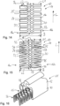
- eine Draufsicht auf ein Verstärkungsband gemäß einer ersten Ausführungsform;
- Fig. 2
- eine Vorderansicht des Verstärkungsbandes von
Fig. 1 ; - Fig. 3
- eine perspektivische Ansicht des zu einem U-Profil umgeformten Verstärkungsbandes von
Fig. 1 ; - Fig. 4
- eine perspektivische Darstellung eines Dichtungsstrangs mit dem zu einem U-Profil umgeformten Verstärkungsband von
Fig. 2 ; - Fig. 5
- eine Vorderansicht eines Verstärkungsbandes gemäß einer zweiten Ausführungsform;
- Fig. 6
- eine perspektivische Ansicht des zu einem U-Profil umgeformten Verstärkungsbandes gemäß der zweiten Ausführungsform;
- Fig. 7
- eine perspektivische Darstellung eines Dichtungsstrangs mit dem zu einem U-Profil umgeformten Verstärkungsband von
Fig. 6 ; - Fig. 8
- eine Draufsicht auf ein Verstärkungsband gemäß einer dritten Ausführungsform;
- Fig. 9
- eine Vorderansicht des Verstärkungsbandes von
Fig. 8 ; - Fig. 10
- eine perspektivische Ansicht des zu einem U-Profil umgeformten Verstärkungsbands von
Fig. 8 ; - Fig. 11
- eine Draufsicht auf ein Verstärkungsband gemäß einer vierten Ausführungsform;
- Fig. 12
- eine Vorderansicht des Verstärkungsbandes von
Fig. 11 ; - Fig. 13
- eine perspektivische Ansicht des zu einem U-Profil umgeformten Verstärkungsbandes von
Fig. 11 ; - Fig. 14
- eine Draufsicht auf ein Verstärkungsband gemäß einer fünften Ausführungsform;
- Fig. 15
- eine Draufsicht auf ein Verstärkungsband gemäß einer sechsten Ausführungsform; und
- Fig. 16
- eine perspektivische Darstellung eines Dichtungsstranges mit dem zu einem U-Profil umgeformten Verstärkungsband von
Fig. 15 . - In
Fig. 1 ist ein Verstärkungsband 10 gezeigt, das zur Armierung eines inFig. 3 dargestellten Formkörpers 11 dient. Der Formkörper 11 ist vorliegend ein Dichtungsstrang 12 für ein nicht dargestelltes Fahrzeug, der eine Dichtlippe 28 und einen Aufsteckschacht 30 aufweist. - Das Verstärkungsband 10 weist eine Breite B zwischen 15 mm und 60 mm, insbesondere zwischen 20 mm und 45 mm, und eine Dicke D zwischen 0,46 mm und 0,84 mm, insbesondere zwischen 0,5 mm und 0,8 mm, weiterhin insbesondere zwischen 0,57 mm und 0,77 mm.
- Das Verstärkungsband 10 weist einen bandförmigen Grundkörper 14 auf, der aus einem ersten Randabschnitt 16a, einem zweiten Randabschnitt 16b und einem dazwischen angeordneten Innenabschnitt 18 gebildet ist.
- Jeder der Randabschnitte 16a, 16b weist eine Vielzahl an Lamellen 17 auf, die von Randschlitzen 20 unterbrochen werden. Wie in
Fig. 1 ersichtlich ist, erstrecken sich die Randschlitze 20 von einem Rand 22 des Grundkörpers 14 quer zur Längsrichtung L nach innen, wobei sich immer zwei Randschlitze 20 gegenüber liegen. Die Randschlitze 20 sind nach innen keilförmig ausgebildet. - In dem Innenabschnitt 18 sind Innenschlitze 24 eingebracht, die zu beiden Seiten hin keilförmig ausgebildet sind. Wie in
Fig. 1 ersichtlich ist, ist abwechselnd in Längsrichtung L des Verstärkungsbandes zwischen zwei Randschlitzen 22 jeweils ein Innenschlitz 24 angeordnet und zwischen jeweils zwei aufeinanderfolgenden Paaren von Randschlitzen 20 sind zwei sich gegenüberliegende Innenschlitze 24 angeordnet. Die Randschlitze 20 weisen eine Länge L1 auf, die ca. ein Drittel der Breite B des Verstärkungsbandes 10 entspricht, und die Innenschlitze 24 weisen eine Länge L2 auf, die zwischen 1/8 und 2/3 der Breite B des Verstärkungsbandes 10 entspricht. - Die Randschlitze 20 und die Innenschlitze 24 werden durch rotatives Schneiden oder Stanzen des Grundkörpers 14 erzeugt und durch Recken, das heißt, durch Ziehen des Grundkörpers 14 in Längsrichtung L, beispielsweise mittels Walzstrecken, in die in
Fig. 1 dargestellte Form aufgeweitet. Eine Öffnungsweite der Randschlitze 22 und der Innenschlitze 24 kann zwischen 1 mm und 4 mm betragen. Die Lamellen 17 können eine Breite zwischen 2,5 und 4,5 mm aufweisen. - Wie zudem in
Fig. 1 ersichtlich ist, überlappen sich die Randschlitze 20 und die Innenschlitze 24 quer zur Längsrichtung L, wobei die überlappenden Randschlitze 20 und Innenschlitze 24 durch Stege 25 voneinander getrennt sind, die eine Breite zwischen 1 mm und 3 mm aufweisen. - Das Verstärkungsband 10 ist aus einer Aluminium-Magnesium-Legierung gemäß der Legierungsgruppe EN AW-5xxx. Der Magnesium-Anteil in der Legierung kann zwischen ca. 0,2 % und 5,6 % betragen. Zudem kann die Aluminium-Magnesium-Legierung noch weitere Bestandteile, wie beispielsweise Silizium (Si), Eisen (Fe), Kupfer (Cu), Mangan (Mn), Magnesium (Mg), Chrom (Cr), Titan (Ti) und/oder Zink (Zn), enthalten. Die Aluminium-Magnesium-Legierung des Verstärkungsbandes wird behandelt, beispielsweise gewalzt, geglüht und/oder wärmebehandelt, um die Festigkeit des Verstärkungsbandes 10 zu erhöhen. Dadurch weist der Grundkörper 14 in einem Zustand Hxy eine Zugfestigkeit auf, die größer ist als die Zugfestigkeit einer korrespondierenden Aluminium-Magnesium-Legierung gemäß der Legierungsgruppe EN AW-5xxx im gleichen Zustand Hxy. So kann die Zugfestigkeit der Aluminium-Magnesium-Legierung des Verstärkungsbandes 10 im Zustand Hxy bis zu 40 N/mm2 höher sein als die Zugfestigkeit einer korrespondierenden Aluminium-Magnesium-Legierung gemäß der Legierungsgruppe EN AW-5xxx im ZustandHxy.
- Beispielsweise weist ein behandelte Aluminium-Magnesium-Legierung EN AW-5754 im Werkstoffzustand H22 und mit einer Materialdicke von 0,8 mm eine Zugfestigkeit Rm von 271 bis 310 MPa und eine Streckgrenze Rp0,2 von min. 130 MPa und eine Bruchdehnung A50 von min. 8 % auf. Im Vergleich dazu weist eine Aluminium-Magnesium-Legierung EN AW-5754 im Werkstoffzustand H22 und mit einer Materialdicke von 0,8 mm nach EN 485-2 eine Zugfestigkeit Rm von 220 bis 270 MPa auf.
- Beispielsweise weist eine behandelte Aluminium-Magnesium-Legierung EN AW-5454 im Werkstoffzustand 0/H111 und mit einer Materialdicke von 0,80 mm eine Zugfestigkeit Rm von 276 bis 305 MPa, eine Streckgrenze Rp0,2 von min. 85 MPa und eine Bruchdehnung A50 von min. 13% auf. Im Vergleich dazu weist eine Aluminium-Magnesium-Legierung EN AW-5454 im Werkstoffzustand 0/H111 und mit einer Materialdicke von 0,8 mm nach EN 485-2 eine Zugfestigkeit Rm von 215 bis 275 MPa auf.
- Alternativ oder zusätzlich kann zur Erhöhung der Festigkeit des Verstärkungsbandes 10 der Grundkörper 14 in einem Zustand Hxy eine Streckgrenze aufweisen, die kleiner als die Streckgrenze einer korrespondierenden Aluminium-Magnesium-Legierung gemäß der Legierungsgruppe EN AW-5xxx im gleichen Zustand Hxy ist.
- Beispielsweise weist ein behandelte Aluminium-Magnesium-Legierung EN AW-5754 im Werkstoffzustand H22 und einer Materialdicke von 0,6 mm eine Zugfestigkeit Rm von 220 bis 270 MPa und eine Streckgrenze Rp0,2 von 90 bis 129 MPa und eine Bruchdehnung A50 von min. 10 % auf. Im Vergleich dazu weist eine Aluminium-Magnesium-Legierung EN AW-5754 im Werkstoffzustand H22 und einer Materialdicke von 0,6 mm nach EN 485-2 eine Streckgrenze Rp02 von mindestens 130 MPa und eine Bruchdehnung A50 von min. 8% auf.
- Durch die Erhöhung der Festigkeit des Verstärkungsbandes, indem die Zugfestigkeit der Aluminium-Magnesium-Legierung im Vergleich zu der Zugfestigkeit einer korrespondieren Aluminium-Magnesium-Legierung gemäß der Legierungsgruppe EN AW-5xxx erhöht ist und/oder die Streckgrenze der Aluminium-Magnesium-Legierung im Vergleich zu der Streckgrenze einer korrespondieren Aluminium-Magnesium-Legierung gemäß der Legierungsgruppe EN AW-5xxx verringert ist, kann das Verstärkungsband 10 weiter gereckt werden. Dadurch kann der Materialeinsatz minimiert und das Gewicht reduziert werden.
- Zudem kann durch die Reduzierung der Streckgrenze beim behandelten Werkstoff der Mindestwert für die Bruchdehnung erhöht werden. Dadurch erhöht sich die Umformbarkeit des Verstärkungsbandes. Es kann beispielsweise weiter gereckt werden und ist dadurch stabiler in der Herstellung und bei der Weiterverarbeitung.
- Somit kann die Zugfestigkeit und/oder die Streckgrenze einer Aluminium-Magnesium-Legierung gemäß der Legierungsgruppe EN AW-5xxx in einem Zustand Hxy im Vergleich zu der korrespondierenden Aluminium-Magnesium-Legierung gemäß der Legierungsgruppe EN AW-5xxx in dem gleichen Zustand Hxy erniedrigt und/oder erhöht werden, indem die Aluminium-Magnesium-Legierung gemäß der Legierungsgruppe EN AW-5xxx mit dem Zustand Hxy behandelt, insbesondere gewalzt, geglüht oder wärmebehandelt wird.
- Zur Armierung des in
Fig. 4 dargestellten Dichtungsstrangs 12 wird das Verstärkungsband 10 zu einem U-förmigen Profil 26 gebogen, wie dies inFig. 3 dargestellt ist. Anschließend wird das U-Profil 26 in einem Extrusionsverfahren mit einem Kunststoff oder elastomeren Material umspritzt, so dass ein als Dichtungsstrang 12 ausgebildeter Formkörper 11 entsteht. - In den
Figuren 5 bis 7 ist eine zweite Ausführungsform des Verstärkungsbands 10 gezeigt, die sich von der ersten Ausführungsform dadurch unterscheidet, dass eine Dicke D1 der Randabschnitte 16a, 16b, insbesondere der Ränder 22, größer als eine Dicke D2 des Innenabschnitts 18 ist. Dadurch wird eine Beschädigung des Formkörpers 11 vermieden. - In den
Figuren 8 bis 10 ist eine dritte Ausführungsform des Verstärkungsbandes 10 gezeigt, die sich von den anderen beiden Ausführungsformen durch die Anordnung der Randschlitze 20 und der Innenschlitze 24 unterscheidet. - Wie in
Fig. 8 ersichtlich ist, sind abwechselnd in Längsrichtung L des Verstärkungsbandes 10 paarweise zwei Randschlitze 20 einander gegenüberliegend und in Längsrichtung L versetzt dazu ein Innenschlitz 24 in den Grundkörper 14 eingebracht. - Die Randschlitze 20 weisen eine Länge L1 auf, die ca. ein Drittel der Breite B des Verstärkungsbandes 10 entspricht, und die Innenschlitze 24 weisen eine Länge L2 auf, die zwischen 1/8 und 2/3 der Breite B des Verstärkungsbandes 10 entspricht.
- Wie insbesondere in
Fig. 9 ersichtlich ist, ist die Dicke D1 der Randabschnitte 16a, 16b des Verstärkungsbandes 10 der dritten Ausführungsform größer als die Dicke D2 des Innenabschnitts 18. In einer nicht dargestellten Ausführungsform kann das Verstärkungsband 10 der dritten Ausführungsform wie das Verstärkungsband 10 der ersten Ausführungsform eine quer zur Längsrichtung L gleichmäßige Dicke D aufweisen. - Das in
Fig. 8 dargestellte Verstärkungsband 10 wird zu einem U-förmigen Profil 26 gebogen, wie dies inFig. 10 dargestellt ist, und in einem Extrusionsverfahren mit einem Kunststoff oder elastomeren Material umspritzt, um einen Dichtungsstrang, wie dieser in denFiguren 4 und7 gezeigt ist, zu erzeugen. - In den
Figuren 11 bis 13 ist eine vierte Ausführungsform des Verstärkungsbandes 10 gezeigt, die sich von der dritten Ausführungsform in der Länge L1 der Randschlitze und der Länge L2 der Innenschlitze unterscheidet. - Ein Vergleich der
Fig. 8 mitFig. 11 veranschaulicht, dass bei der vierten Ausführungsform im Vergleich zu der dritten Ausführungsform die Länge L1 der Randschlitze 20 größer und die Länge L2 der Innenschlitze 24 kleiner ist. - Die Randschlitze 20 der vierten Ausführungsform weisen eine Länge L1 auf, die ca. der Hälfte der Breite B des Verstärkungsbandes 10 entspricht, und die Innenschlitze 24 weisen eine Länge L2 auf, die zwischen 1/8 und 2/3 der Breite B des Verstärkungsbandes 10 entspricht. Dadurch weist das zu einem U-förmigen Profil 26 gebogenene Verstärkungsband der vierten Ausführungsform im Vergleich zu dem U-förmigen Profil der dritten Ausführungsform eine größere Höhe bei einer gleichzeitig geringeren Breite auf.
- Wie insbesondere in
Fig. 12 ersichtlich ist, ist die Dicke D1 der Randabschnitte 16a, 16b des Verstärkungsbandes 10 der vierten Ausführungsform größer als die Dicke D2 des Innenabschnitts 18. In einer nicht dargestellten Ausführungsform kann das Verstärkungsband 10 der vierten Ausführungsform wie das Verstärkungsband 10 der ersten Ausführungsform eine quer zur Längsrichtung L gleichmäßige Dicke D aufweisen. - Das in
Fig. 11 dargestellte Verstärkungsband 10 wird zu einem U-förmigen Profil 26 gebogen, wie dies inFig. 13 dargestellt ist, und in einem Extrusionsverfahren mit einem Kunststoff oder elastomeren Material umspritzt, um einen Dichtungsstrang, wie dieser in denFiguren 4 und7 gezeigt ist, zu erzeugen. - In
Fig. 14 ist eine fünfte Ausführungsform des Verstärkungsbandes 10 gezeigt, die sich von den anderen Ausführungsformen durch die Anordnung der Randschlitze 20 und der Innenschlitze 24 unterscheidet. - Wie in
Fig. 14 ersichtlich ist, sind sowohl die Randschlitze 20 als auch die Innenschlitze 24 in Längsrichtung L versetzt zueinander angeordnet. Insbesondere sind abwechselnd in Längsrichtung L des Verstärkungsbandes 10 ein Randschlitz 20 eines ersten Randabschnittes 16a und ein Innenschlitz 24 einander gegenüberliegend und in Längsrichtung L versetzt dazu ein Randschlitz 20 eines zweiten Randabschnittes 16b und ein Innenschlitz 24 einander gegenüberliegend angeordnet. - Die Randschlitze 20 der fünften Ausführungsform weisen eine Länge L1 auf, die ca. 1/3 der Breite B des Verstärkungsbandes 10 entspricht, und die Innenschlitze 24 weisen eine Länge L2 auf, die zwischen 1/8 und 2/3 der Breite B des Verstärkungsbandes 10 entspricht.
- Bei der in
Fig. 14 dargestellten fünften Ausführungsform des Verstärkungsbandes 10 können die Randabschnitte 16a, 16b eine Dicke D1 aufweisen, die, wie in denFiguren 5 ,9 und12 dargestellt ist, größer als die Dicke D2 des Innenabschnittes 18 ist, oder die, wie inFig. 2 dargestellt ist, gleich der Dicke D2 des Innenabschnittes 18 ist. - Das in
Fig. 14 dargestellte Verstärkungsband 10 wird zu einem U-förmigen Profil 26 gebogen, wie dies in denFiguren 4, 6 ,10 und 13 dargestellt ist, und in einem Extrusionsverfahren mit einem Kunststoff oder elastomeren Material umspritzt, um einen Dichtungsstrang, wie dieser in denFiguren 4 und7 gezeigt ist, zu erzeugen. - In den
Figuren 15 und 16 ist eine sechste Ausführungsform des Verstärkungsbandes 10 gezeigt, die sich von den anderen Ausführungsformen in der Ausgestaltung der Randschlitze 20 und der Innenschlitze 24 unterscheidet. - Wie in
Fig. 15 ersichtlich ist, sind die Randschlitze 20 V-förmig ausgebildet, indem die Randschlitze 20 spitz nach innen zulaufen. - Die Innenschlitze 24 sind aus zwei ersten Reihen 32 mit einer ersten Kontur 34 und aus einer zweiten Reihe 36 mit einer zweiten Kontur 36 gebildet, wobei die Innenschlitze 24 der ersten Reihe 32 länger sind als die Innenschlitze 24 der zweiten Reihe 36. Die erste Kontur 34 weist näherungsweise eine Tropfenform auf und die zweite Kontur 36 weist näherungsweise die Form eines Hexaeders auf.
- Wie in
Fig. 15 ersichtlich ist, ist abwechselnd in Längsrichtung L des Verstärkungsbandes 10 zwischen zwei Randschlitzen 22 jeweils ein Innenschlitz 24 der zweiten Reihe 36 angeordnet und zwischen jeweils zwei aufeinanderfolgenden Paaren von Randschlitzen 20 sind zwei sich gegenüberliegende Innenschlitze 24 der ersten Reihe 32 angeordnet. - Die Randschlitze 20 der sechsten Ausführungsform weisen eine Länge L1 auf, die ca. 1/3 der Breite B des Verstärkungsbandes 10 entspricht. Die Innenschlitze 24 der ersten Reihe 32 weisen eine Länge L2 auf, die ca. 1/3 der Breite B des Verstärkungsbandes 10 entspricht und die Innenschlitze 24 der zweiten Reihe 36 weisen eine Länge L2 auf, die ca. 1/8 der Breite B des Verstärkungsbandes 10 entspricht.
- Bei der in
Fig. 15 dargestellten sechsten Ausführungsform des Verstärkungsbandes 10 können die Randabschnitte 16a, 16b eine Dicke D1 aufweisen, die, wie in denFiguren 5 ,9 und12 dargestellt ist, größer als die Dicke D2 des Innenabschnittes 18 ist, oder die, wie inFig. 2 dargestellt ist, gleich der Dicke D2 des Innenabschnittes 18 ist. - Das in
Fig. 15 dargestellte Verstärkungsband 10 wird zu einem U-förmigen Profil 26 gebogen, wie dies in denFiguren 4, 6 ,10 und 13 dargestellt ist, und in einem Extrusionsverfahren mit einem Kunststoff oder elastomeren Material umspritzt, um den inFig. 16 dargestellten Dichtungsstrang 12 zu erzeugen. - Durch die Erhöhung und/oder Reduzierung der Streckgrenze und/oder der Zugfestigkeit der Aluminium-Magnesium-Legierung kann das Verstärkungsband 10 weiter gereckt werden, das heißt in die Länge gezogen werden. Dadurch kann der Materialeinsatz reduziert und gleichzeitig das Gewicht des Verstärkungsbandes 10 verringert werden.
-
- 10
- Verstärkungsband
- 11
- Formkörper
- 12
- Dichtungsstrang
- 14
- bandförmiger Grundkörper
- 16a
- erster Randabschnitt
- 16b
- zweiter Randabschnitt
- 17
- Lamellen
- 18
- Innenabschnitt
- 20
- Randschlitz
- 22
- Rand
- 24
- Innenschlitz
- 25
- Steg
- 26
- U-Profil
- 28
- Dichtlippe
- 30
- Aufsteckschacht
- 32
- erste Reihe
- 34
- erste Kontur
- 36
- zweite Reihe
- 38
- zweite Kontur
- L
- Längsrichtung
- B
- Breite des Verstärkungsbandes
- D
- Dicke des Verstärkungsbandes
- L1
- Länge eines Randschlitzes
- L2
- Länge eines Innenschlitzes
- Bs
- Breite des Stegs
- D1
- Dicke eines Randabschnittes
- D2
- Dicke des Innenabschnittes
Claims (15)
- Verstärkungsband (10) für einen Formkörper (11) aus einer spritzfähigen Formmasse, aufweisend einen bandförmigen Grundkörper (14) aus einer Aluminium-Magnesium-Legierung gemäß der Legierungsgruppe EN AW-5xxx, dadurch gekennzeichnet, dass die Aluminium-Magnesium-Legierung des bandförmigen Grundkörpers (14) eine Streckgrenze und/oder eine Zugfestigkeit aufweist, die höher und/oder niedriger als die Streckgrenze und/oder die Zugfestigkeit einer korrespondierenden Aluminium-Magnesium-Legierung gemäß der Legierungsgruppe EN AW-5xxx ist.
- Verstärkungsband (10) nach Anspruch 1, dadurch gekennzeichnet, dass die Streckgrenze und/oder die Zugfestigkeit der Aluminium-Magnesium-Legierung des bandförmigen Grundkörpers (14) zwischen 5% und 50% höher und/oder niedriger als die Streckgrenze und/oder die Zugfestigkeit einer korrespondierenden Aluminium-Magnesium-Legierung gemäß der Legierungsgruppe EN AW-5xxx ist.
- Verstärkungsband (10) nach Anspruch 1 oder 2, dadurch gekennzeichnet, dass die Aluminium-Magnesium-Legierung des Grundkörpers (14) in einem Zustand Hxy eine höhere Zugfestigkeit als eine korrespondierende Aluminium-Magnesium-Legierung gemäß der Legierungsgruppe EN AW-5xxx im Zustand Hxy aufweist.
- Verstärkungsband (10) nach einem der vorhergehenden Ansprüche, dadurch gekennzeichnet, dass die Aluminium-Magnesium-Legierung des Grundkörpers (14) in einem Zustand Hxy eine niedrigere Streckgrenze als eine korrespondierende Aluminium-Magnesium-Legierung gemäß der Legierungsgruppe EN AW-5xxx im Zustand Hxy aufweist.
- Verstärkungsband (10) nach einem der vorhergehenden Ansprüche, dadurch gekennzeichnet, dass die Aluminium-Magnesium-Legierung geglüht oder wärmebehandelt ist.
- Verstärkungsband (10) nach einem der vorhergehenden Ansprüche, dadurch gekennzeichnet, dass der Grundkörper (14) eine Dicke (D) zwischen 0,46 mm und 0,84 mm, insbesondere zwischen 0,5 mm und 0,8 mm, weiterhin insbesondere zwischen 0,57 mm und 0,77 mm, aufweist.
- Verstärkungsband (10) nach einem der vorhergehenden Ansprüche, dadurch gekennzeichnet, dass der Grundkörper (14) eine Vielzahl an aufgeweiteten Randschlitzen (20), die sich von Randabschnitten (16a, 16b) des Grundkörpers (14) quer zu seiner Längsrichtung (L) nach innen erstrecken, und eine Vielzahl an aufgeweiteten Innenschlitzen (24), die in einem zwischen den Randabschnitten (16a, 16b) des Grundkörpers (14) befindlichen Innenabschnitt (18) angeordnet sind, aufweist.
- Verstärkungsband (10) nach Anspruch 7, dadurch gekennzeichnet, dass eine Öffnungsweite der Randschlitze (20) und/oder der Innenschlitze (24) zwischen 0,5 mm und 4 mm beträgt.
- Verstärkungsband nach Anspruch 7 oder 8, dadurch gekennzeichnet, dass die Randschlitze (20) eine Länge (L1) aufweisen, die zwischen einem Drittel und der Hälfte einer Breite (B) des Verstärkungsbandes (10) entspricht, und die Innenschlitze (24) weisen eine Länge (L2) auf, die zwischen 1/8 und 2/3 der Breite (B) des Verstärkungsbandes (10) entspricht.
- Verstärkungsband (10) nach einem der Ansprüche 7 bis 9, dadurch gekennzeichnet, dass die Innenschlitze (24) aus wenigstens einer ersten Reihe (32) mit einer ersten Kontur (34) und aus wenigstens einer zweiten Reihe (36) mit einer zweiten Kontur (38) gebildet sind.
- Verstärkungsband (10) nach einem der Ansprüche 7 bis 10, dadurch gekennzeichnet, dass sich die Randschlitze (20) und die Innenschlitze (24) quer zur Längsrichtung (L) überlappen, wobei die überlappenden Randschlitze (20) und Innenschlitze (24) durch Stege (25) voneinander getrennt sind, wobei die Stege (25) eine Breite (Bs) zwischen 1 mm und 3 mm aufweisen.
- Verstärkungsband (10) nach einem der Ansprüche 7 bis 11, dadurch gekennzeichnet, dass abwechselnd in Längsrichtung (L) des Verstärkungsbandes (10) zwei Randschlitze (20) einander gegenüberliegend und in Längsrichtung (L) versetzt dazu ein Innenschlitz (24) angeordnet sind, oder dass abwechselnd in Längsrichtung (L) des Verstärkungsbandes (10) ein Randschlitz (20) eines ersten Randabschnittes (16a) und ein Innenschlitz (24) einander gegenüberliegend und in Längsrichtung (L) versetzt dazu ein Randschlitz (20) eines zweiten Randabschnittes (16b) und ein Innenschlitz (24) einander gegenüberliegend angeordnet sind, oder dass abwechselnd in Längsrichtung (L) des Verstärkungsbandes (10) zwischen zwei sich paarweise gegenüberliegenden Randschlitzen (20) ein Innenschlitz (24) und in Längsrichtung (L) versetzt dazu zwei sich gegenüberliegende Innenschlitze (24) angeordnet sind.
- Verstärkungsband (10) nach einem der vorhergehenden Ansprüche, dadurch gekennzeichnet, dass eine Dicke (D1) der Randabschnitte (16) größer als eine Dicke (D2) des Innenabschnittes (18) ist.
- Formkörper (11) aus einer spritzfähigen Formmasse, aufweisend ein Verstärkungsband (10) nach einem der Ansprüche 1 bis 13.
- Formkörper (11) nach Anspruch 14, dadurch gekennzeichnet, dass das Verstärkungsband (10) zu einem V-förmigen Profil oder einem U-Förmigen Profil umgeformt ist, und/oder dass der Formkörper (11) ein Dichtungsstrang (12) für ein Fahrzeug ist.
Applications Claiming Priority (2)
| Application Number | Priority Date | Filing Date | Title |
|---|---|---|---|
| DE202022100638.5U DE202022100638U1 (de) | 2022-02-03 | 2022-02-03 | Verstärkungsband für einen Formkörper aus einer spritzfähigen Formmasse sowie Formkörper mit einem derartigen Verstärkungsband |
| PCT/EP2023/052652 WO2023148313A1 (de) | 2022-02-03 | 2023-02-03 | Verstärkungsband für einen formkörper aus einer spritzfähigen formmasse sowie formkörper mit einem derartigen verstärkungsband |
Publications (2)
| Publication Number | Publication Date |
|---|---|
| EP4426573A1 EP4426573A1 (de) | 2024-09-11 |
| EP4426573B1 true EP4426573B1 (de) | 2025-04-02 |
Family
ID=85321180
Family Applications (1)
| Application Number | Title | Priority Date | Filing Date |
|---|---|---|---|
| EP23706532.1A Active EP4426573B1 (de) | 2022-02-03 | 2023-02-03 | Verstärkungsband für einen formkörper aus einer spritzfähigen formmasse sowie formkörper mit einem derartigen verstärkungsband |
Country Status (5)
| Country | Link |
|---|---|
| EP (1) | EP4426573B1 (de) |
| DE (1) | DE202022100638U1 (de) |
| ES (1) | ES3030168T3 (de) |
| PL (1) | PL4426573T3 (de) |
| WO (1) | WO2023148313A1 (de) |
Citations (6)
| Publication number | Priority date | Publication date | Assignee | Title |
|---|---|---|---|---|
| DE69104445T2 (de) | 1990-08-28 | 1995-03-23 | Draftex Ind Ltd | Verstärkungen für flexible Streifen. |
| US5865931A (en) | 1997-02-10 | 1999-02-02 | Aluminum Company Of America | Reflective vehicle trim |
| FR2852074A1 (fr) | 2003-03-05 | 2004-09-10 | Hutchinson | Joint d'etancheite a pince de fixation ayant au moins une armature de renfort en aluminium |
| FR3066951A1 (fr) | 2017-06-05 | 2018-12-07 | Sealynx International | Profile, notamment pour vehicule automobile, avec un insert lamine. |
| DE202021104735U1 (de) | 2021-09-02 | 2021-10-04 | Bfc Fahrzeugteile Gmbh | Metallband |
| WO2021239269A1 (de) | 2020-05-26 | 2021-12-02 | Cqlt Saargummi Technologies S.À.R.L. | Verstärkungsprofil sowie extrudierter dichtungs- oder/und kantenschutzstrang |
Family Cites Families (2)
| Publication number | Priority date | Publication date | Assignee | Title |
|---|---|---|---|---|
| DE10033454A1 (de) | 2000-03-31 | 2001-10-18 | Alfred Steinl | Lamellenband |
| DE102016005074A1 (de) | 2016-04-27 | 2017-11-02 | Lwb Steinl Gmbh & Co. Kg | Gerüstband mit Verstärkungsmittel |
-
2022
- 2022-02-03 DE DE202022100638.5U patent/DE202022100638U1/de active Active
-
2023
- 2023-02-03 PL PL23706532.1T patent/PL4426573T3/pl unknown
- 2023-02-03 WO PCT/EP2023/052652 patent/WO2023148313A1/de not_active Ceased
- 2023-02-03 ES ES23706532T patent/ES3030168T3/es active Active
- 2023-02-03 EP EP23706532.1A patent/EP4426573B1/de active Active
Patent Citations (6)
| Publication number | Priority date | Publication date | Assignee | Title |
|---|---|---|---|---|
| DE69104445T2 (de) | 1990-08-28 | 1995-03-23 | Draftex Ind Ltd | Verstärkungen für flexible Streifen. |
| US5865931A (en) | 1997-02-10 | 1999-02-02 | Aluminum Company Of America | Reflective vehicle trim |
| FR2852074A1 (fr) | 2003-03-05 | 2004-09-10 | Hutchinson | Joint d'etancheite a pince de fixation ayant au moins une armature de renfort en aluminium |
| FR3066951A1 (fr) | 2017-06-05 | 2018-12-07 | Sealynx International | Profile, notamment pour vehicule automobile, avec un insert lamine. |
| WO2021239269A1 (de) | 2020-05-26 | 2021-12-02 | Cqlt Saargummi Technologies S.À.R.L. | Verstärkungsprofil sowie extrudierter dichtungs- oder/und kantenschutzstrang |
| DE202021104735U1 (de) | 2021-09-02 | 2021-10-04 | Bfc Fahrzeugteile Gmbh | Metallband |
Non-Patent Citations (11)
Also Published As
| Publication number | Publication date |
|---|---|
| EP4426573A1 (de) | 2024-09-11 |
| DE202022100638U1 (de) | 2023-05-09 |
| WO2023148313A1 (de) | 2023-08-10 |
| ES3030168T3 (en) | 2025-06-26 |
| PL4426573T3 (pl) | 2025-08-04 |
Similar Documents
| Publication | Publication Date | Title |
|---|---|---|
| EP0425059B1 (de) | Rohrförmiges Stahlprofil für die Türverstärkung | |
| DE102011005977B4 (de) | Verstärkungsblech einer B-Säule | |
| DE2735473C2 (de) | Verwendung einer AlMgSi-Knetlegierung für die Herstellung von gestanzten und verformten Kraftfahrzeugteilen | |
| DE3843057C2 (de) | Dichtungsprofilleiste | |
| DE19680170C2 (de) | Sicherheitsgurtaufhängungs- und halteteil | |
| DE102014216225A1 (de) | Strukturbauteil und Verfahren zur Herstellung eines Strukturbauteils | |
| EP3265365A1 (de) | Pressgehärtetes blechformteil mit unterschiedlichen blechdicken und festigkeiten | |
| EP2914391A1 (de) | Aluminiumverbundwerkstoff und verfahren zur umformung | |
| DE112009004763T5 (de) | Angepasster rohling und verfahren, um daraus ein bauteil herzustellen | |
| EP3924198B1 (de) | Metallband | |
| DE102005017375B4 (de) | Strangpreßerzeugnis mit Kern | |
| DE102009007309A1 (de) | Profilteil als Karosseriekomponente eines Kraftfahrzeuges | |
| EP4426573B1 (de) | Verstärkungsband für einen formkörper aus einer spritzfähigen formmasse sowie formkörper mit einem derartigen verstärkungsband | |
| WO2005016624A1 (de) | Hybridbauteil und zugehöriges herstellungsverfahren | |
| EP3497256B1 (de) | Aluminiumlegierung und aluminiumlegierungsband für den fussgängeraufprallschutz | |
| DE10055338C1 (de) | Verfahren zum Herstellen eines bei niedrigen Verformungsgraden kaltverformten Kaltbandes | |
| EP3519120B1 (de) | Verfahren zur herstellung eines geformten bauteils mit einem masshaltigen zargenbereich | |
| DE102010015734A1 (de) | Einlegeblech und Verfahren zu dessen Herstellung | |
| EP4426572B1 (de) | Verstärkungsband für einen formkörper aus einer spritzfähigen formmasse sowie formkörper mit einem derartigen verstärkungsband | |
| EP1441921B1 (de) | Platine, karosserieteil und verfahren zur herstellung eines solchen karosserieteils | |
| DE10247678B4 (de) | Wechselschnittband als Trägerband für Karosseriedichtungen | |
| EP2924135B1 (de) | Verfahren zur Herstellung eines Bandes aus einer hochumformbaren, mittelfesten Aluminiumlegierung für Halbzeuge oder Bauteile von Kraftfahrzeugen | |
| DE102024119692A1 (de) | Massgewalzter rohling zum einsatz beim heissprägen von automobilteilen und verfahren zur herstellung von heissgeprägten automobilteilen | |
| EP1495924B1 (de) | Karosserieteil, insbesondere Fronthaube, für ein Kraftfahrzeug | |
| DE102022114057A1 (de) | Unterschiedliche Blechdicken und Festigkeiten aufweisendes pressgehärtetes Blechformteil |
Legal Events
| Date | Code | Title | Description |
|---|---|---|---|
| STAA | Information on the status of an ep patent application or granted ep patent |
Free format text: STATUS: UNKNOWN |
|
| STAA | Information on the status of an ep patent application or granted ep patent |
Free format text: STATUS: THE INTERNATIONAL PUBLICATION HAS BEEN MADE |
|
| PUAI | Public reference made under article 153(3) epc to a published international application that has entered the european phase |
Free format text: ORIGINAL CODE: 0009012 |
|
| STAA | Information on the status of an ep patent application or granted ep patent |
Free format text: STATUS: REQUEST FOR EXAMINATION WAS MADE |
|
| 17P | Request for examination filed |
Effective date: 20240607 |
|
| AK | Designated contracting states |
Kind code of ref document: A1 Designated state(s): AL AT BE BG CH CY CZ DE DK EE ES FI FR GB GR HR HU IE IS IT LI LT LU LV MC ME MK MT NL NO PL PT RO RS SE SI SK SM TR |
|
| REG | Reference to a national code |
Ref country code: DE Ref legal event code: R079 Free format text: PREVIOUS MAIN CLASS: B60J0010180000 Ipc: F16J0015020000 Ref country code: DE Ref legal event code: R079 Ref document number: 502023000784 Country of ref document: DE Free format text: PREVIOUS MAIN CLASS: B60J0010180000 Ipc: F16J0015020000 |
|
| GRAP | Despatch of communication of intention to grant a patent |
Free format text: ORIGINAL CODE: EPIDOSNIGR1 |
|
| STAA | Information on the status of an ep patent application or granted ep patent |
Free format text: STATUS: GRANT OF PATENT IS INTENDED |
|
| RIC1 | Information provided on ipc code assigned before grant |
Ipc: B29C 48/12 20190101ALI20241021BHEP Ipc: B29K 705/02 20060101ALI20241021BHEP Ipc: B29K 21/00 20060101ALI20241021BHEP Ipc: B60J 10/18 20160101ALI20241021BHEP Ipc: C22C 21/06 20060101ALI20241021BHEP Ipc: B29C 48/285 20190101ALI20241021BHEP Ipc: B29C 48/154 20190101ALI20241021BHEP Ipc: F16J 15/12 20060101ALI20241021BHEP Ipc: B60J 10/80 20160101ALI20241021BHEP Ipc: B60J 10/32 20160101ALI20241021BHEP Ipc: B21D 11/10 20060101ALI20241021BHEP Ipc: B21D 28/26 20060101ALI20241021BHEP Ipc: C22F 1/047 20060101ALI20241021BHEP Ipc: F16J 15/02 20060101AFI20241021BHEP |
|
| INTG | Intention to grant announced |
Effective date: 20241105 |
|
| GRAS | Grant fee paid |
Free format text: ORIGINAL CODE: EPIDOSNIGR3 |
|
| GRAA | (expected) grant |
Free format text: ORIGINAL CODE: 0009210 |
|
| STAA | Information on the status of an ep patent application or granted ep patent |
Free format text: STATUS: THE PATENT HAS BEEN GRANTED |
|
| AK | Designated contracting states |
Kind code of ref document: B1 Designated state(s): AL AT BE BG CH CY CZ DE DK EE ES FI FR GB GR HR HU IE IS IT LI LT LU LV MC ME MK MT NL NO PL PT RO RS SE SI SK SM TR |
|
| DAV | Request for validation of the european patent (deleted) | ||
| DAX | Request for extension of the european patent (deleted) | ||
| REG | Reference to a national code |
Ref country code: GB Ref legal event code: FG4D Free format text: NOT ENGLISH |
|
| REG | Reference to a national code |
Ref country code: CH Ref legal event code: EP |
|
| REG | Reference to a national code |
Ref country code: IE Ref legal event code: FG4D Free format text: LANGUAGE OF EP DOCUMENT: GERMAN |
|
| REG | Reference to a national code |
Ref country code: DE Ref legal event code: R096 Ref document number: 502023000784 Country of ref document: DE |
|
| P01 | Opt-out of the competence of the unified patent court (upc) registered |
Free format text: CASE NUMBER: APP_20600/2025 Effective date: 20250430 |
|
| REG | Reference to a national code |
Ref country code: ES Ref legal event code: FG2A Ref document number: 3030168 Country of ref document: ES Kind code of ref document: T3 Effective date: 20250626 |
|
| REG | Reference to a national code |
Ref country code: NL Ref legal event code: MP Effective date: 20250402 |
|
| PG25 | Lapsed in a contracting state [announced via postgrant information from national office to epo] |
Ref country code: NL Free format text: LAPSE BECAUSE OF FAILURE TO SUBMIT A TRANSLATION OF THE DESCRIPTION OR TO PAY THE FEE WITHIN THE PRESCRIBED TIME-LIMIT Effective date: 20250402 |
|
| PG25 | Lapsed in a contracting state [announced via postgrant information from national office to epo] |
Ref country code: FI Free format text: LAPSE BECAUSE OF FAILURE TO SUBMIT A TRANSLATION OF THE DESCRIPTION OR TO PAY THE FEE WITHIN THE PRESCRIBED TIME-LIMIT Effective date: 20250402 Ref country code: PT Free format text: LAPSE BECAUSE OF FAILURE TO SUBMIT A TRANSLATION OF THE DESCRIPTION OR TO PAY THE FEE WITHIN THE PRESCRIBED TIME-LIMIT Effective date: 20250804 |
|
| REG | Reference to a national code |
Ref country code: LT Ref legal event code: MG9D |
|
| PG25 | Lapsed in a contracting state [announced via postgrant information from national office to epo] |
Ref country code: GR Free format text: LAPSE BECAUSE OF FAILURE TO SUBMIT A TRANSLATION OF THE DESCRIPTION OR TO PAY THE FEE WITHIN THE PRESCRIBED TIME-LIMIT Effective date: 20250703 Ref country code: NO Free format text: LAPSE BECAUSE OF FAILURE TO SUBMIT A TRANSLATION OF THE DESCRIPTION OR TO PAY THE FEE WITHIN THE PRESCRIBED TIME-LIMIT Effective date: 20250702 |
|
| PG25 | Lapsed in a contracting state [announced via postgrant information from national office to epo] |
Ref country code: BG Free format text: LAPSE BECAUSE OF FAILURE TO SUBMIT A TRANSLATION OF THE DESCRIPTION OR TO PAY THE FEE WITHIN THE PRESCRIBED TIME-LIMIT Effective date: 20250402 |
|
| PG25 | Lapsed in a contracting state [announced via postgrant information from national office to epo] |
Ref country code: HR Free format text: LAPSE BECAUSE OF FAILURE TO SUBMIT A TRANSLATION OF THE DESCRIPTION OR TO PAY THE FEE WITHIN THE PRESCRIBED TIME-LIMIT Effective date: 20250402 |
|
| PG25 | Lapsed in a contracting state [announced via postgrant information from national office to epo] |
Ref country code: RS Free format text: LAPSE BECAUSE OF FAILURE TO SUBMIT A TRANSLATION OF THE DESCRIPTION OR TO PAY THE FEE WITHIN THE PRESCRIBED TIME-LIMIT Effective date: 20250702 |
|
| PG25 | Lapsed in a contracting state [announced via postgrant information from national office to epo] |
Ref country code: IS Free format text: LAPSE BECAUSE OF FAILURE TO SUBMIT A TRANSLATION OF THE DESCRIPTION OR TO PAY THE FEE WITHIN THE PRESCRIBED TIME-LIMIT Effective date: 20250802 |
|
| PG25 | Lapsed in a contracting state [announced via postgrant information from national office to epo] |
Ref country code: LV Free format text: LAPSE BECAUSE OF FAILURE TO SUBMIT A TRANSLATION OF THE DESCRIPTION OR TO PAY THE FEE WITHIN THE PRESCRIBED TIME-LIMIT Effective date: 20250402 |
|
| REG | Reference to a national code |
Ref country code: DE Ref legal event code: R026 Ref document number: 502023000784 Country of ref document: DE |
|
| PLBI | Opposition filed |
Free format text: ORIGINAL CODE: 0009260 |
|
| REG | Reference to a national code |
Ref country code: CH Ref legal event code: L11 Free format text: ST27 STATUS EVENT CODE: U-0-0-L10-L11 (AS PROVIDED BY THE NATIONAL OFFICE) Effective date: 20251231 |
|
| PLAB | Opposition data, opponent's data or that of the opponent's representative modified |
Free format text: ORIGINAL CODE: 0009299OPPO |
|
| PG25 | Lapsed in a contracting state [announced via postgrant information from national office to epo] |
Ref country code: DK Free format text: LAPSE BECAUSE OF FAILURE TO SUBMIT A TRANSLATION OF THE DESCRIPTION OR TO PAY THE FEE WITHIN THE PRESCRIBED TIME-LIMIT Effective date: 20250402 Ref country code: SM Free format text: LAPSE BECAUSE OF FAILURE TO SUBMIT A TRANSLATION OF THE DESCRIPTION OR TO PAY THE FEE WITHIN THE PRESCRIBED TIME-LIMIT Effective date: 20250402 |
|
| REG | Reference to a national code |
Ref country code: CH Ref legal event code: L10 Free format text: ST27 STATUS EVENT CODE: U-0-0-L10-L00 (AS PROVIDED BY THE NATIONAL OFFICE) Effective date: 20260114 |
|
| PG25 | Lapsed in a contracting state [announced via postgrant information from national office to epo] |
Ref country code: CZ Free format text: LAPSE BECAUSE OF FAILURE TO SUBMIT A TRANSLATION OF THE DESCRIPTION OR TO PAY THE FEE WITHIN THE PRESCRIBED TIME-LIMIT Effective date: 20250402 |
|
| PG25 | Lapsed in a contracting state [announced via postgrant information from national office to epo] |
Ref country code: EE Free format text: LAPSE BECAUSE OF FAILURE TO SUBMIT A TRANSLATION OF THE DESCRIPTION OR TO PAY THE FEE WITHIN THE PRESCRIBED TIME-LIMIT Effective date: 20250402 |
|
| PG25 | Lapsed in a contracting state [announced via postgrant information from national office to epo] |
Ref country code: SK Free format text: LAPSE BECAUSE OF FAILURE TO SUBMIT A TRANSLATION OF THE DESCRIPTION OR TO PAY THE FEE WITHIN THE PRESCRIBED TIME-LIMIT Effective date: 20250402 |
|
| 26 | Opposition filed |
Opponent name: BFC FAHRZEUGTEILE GMBH Effective date: 20251218 |
|
| PG25 | Lapsed in a contracting state [announced via postgrant information from national office to epo] |
Ref country code: IT Free format text: LAPSE BECAUSE OF FAILURE TO SUBMIT A TRANSLATION OF THE DESCRIPTION OR TO PAY THE FEE WITHIN THE PRESCRIBED TIME-LIMIT Effective date: 20250402 |
|
| PLAX | Notice of opposition and request to file observation + time limit sent |
Free format text: ORIGINAL CODE: EPIDOSNOBS2 |
|
| R26 | Opposition filed (corrected) |
Opponent name: BFC FAHRZEUGTEILE GMBH Effective date: 20251218 |
|
| PGFP | Annual fee paid to national office [announced via postgrant information from national office to epo] |
Ref country code: ES Payment date: 20260319 Year of fee payment: 4 |
|
| PGFP | Annual fee paid to national office [announced via postgrant information from national office to epo] |
Ref country code: DE Payment date: 20260304 Year of fee payment: 4 |
|
| PGFP | Annual fee paid to national office [announced via postgrant information from national office to epo] |
Ref country code: AT Payment date: 20260301 Year of fee payment: 4 |
|
| PGFP | Annual fee paid to national office [announced via postgrant information from national office to epo] |
Ref country code: FR Payment date: 20260223 Year of fee payment: 4 |
|
| PGFP | Annual fee paid to national office [announced via postgrant information from national office to epo] |
Ref country code: TR Payment date: 20260129 Year of fee payment: 4 |
|
| PGFP | Annual fee paid to national office [announced via postgrant information from national office to epo] |
Ref country code: PL Payment date: 20260127 Year of fee payment: 4 |