EP4424618A1 - Linearantrieb für eine kontinuierliche schüttgutfördervorrichtung - Google Patents
Linearantrieb für eine kontinuierliche schüttgutfördervorrichtung Download PDFInfo
- Publication number
- EP4424618A1 EP4424618A1 EP22884811.5A EP22884811A EP4424618A1 EP 4424618 A1 EP4424618 A1 EP 4424618A1 EP 22884811 A EP22884811 A EP 22884811A EP 4424618 A1 EP4424618 A1 EP 4424618A1
- Authority
- EP
- European Patent Office
- Prior art keywords
- primary
- linear
- motor
- linear drive
- conveying device
- Prior art date
- Legal status (The legal status is an assumption and is not a legal conclusion. Google has not performed a legal analysis and makes no representation as to the accuracy of the status listed.)
- Pending
Links
Images
Classifications
-
- B—PERFORMING OPERATIONS; TRANSPORTING
- B65—CONVEYING; PACKING; STORING; HANDLING THIN OR FILAMENTARY MATERIAL
- B65G—TRANSPORT OR STORAGE DEVICES, e.g. CONVEYORS FOR LOADING OR TIPPING, SHOP CONVEYOR SYSTEMS OR PNEUMATIC TUBE CONVEYORS
- B65G23/00—Driving gear for endless conveyors; Belt- or chain-tensioning arrangements
- B65G23/22—Arrangements or mountings of driving motors
- B65G23/23—Arrangements or mountings of driving motors of electric linear motors
-
- B—PERFORMING OPERATIONS; TRANSPORTING
- B65—CONVEYING; PACKING; STORING; HANDLING THIN OR FILAMENTARY MATERIAL
- B65G—TRANSPORT OR STORAGE DEVICES, e.g. CONVEYORS FOR LOADING OR TIPPING, SHOP CONVEYOR SYSTEMS OR PNEUMATIC TUBE CONVEYORS
- B65G45/00—Lubricating, cleaning, or clearing devices
- B65G45/10—Cleaning devices
- B65G45/18—Cleaning devices comprising brushes
Definitions
- This invention belongs to the field of electrical engineering with applications in transportation engineering. It involves the use of a linear induction motor with an active double-faced primary and a new geometry of the linear motor secondary to enable the use of this type of motor in linear movement that performs a closed-loop motion.
- Linear transport equipment such as conventional belt conveyors, uses rotary motors located at the head of the conveyor, coupled to the drum drive shaft of the conveyor. This configuration results in a series of inefficiencies in the transport system, such as the use of tensioners to generate mechanical tension in the belt and generate enough friction on the drive drum to prevent slippage during conveyor operation.
- the proposed solution involves the use of linear motors distributed along the conveyor to maintain constant traction over the entire length of the belt and, thus, reduce the need for conventional tensioners.
- the proposed invention is more resistant to dust and debris since the linear motor can be considered an open motor with a larger iron distance and protected against contaminants through resin impregnation. This reduces or eliminates the problem of motor failure due to particle and water infiltration.
- Linear motors are electric motors that have the same components as rotary electric motors, but they perform linear movement relative to the parts.
- the secondary of a linear motor corresponds to the rotor of a conventional induction rotary motor, and the primary of the linear motor is where the windings and the iron core are located.
- Linear motors are generally low-power motors and have advantages in the direct application of linear movement without the need to convert rotary motion.
- the linear motor of this invention has a modification in its secondary element that allows its application in linear movement in a loop, such as that performed by linear conveyors. They can be implemented in flexible conveyors rubber, metallic conveyors, vertical or horizontal conveyors, and also in short or long-haul conveyors due to their linear distribution and the versatility of installation of these motors, which were designed to be installed in the intervals between rollers of these types of conveyors.
- the secondary presented has the characteristic of not being a continuous element but is divided into several blades forming a train of plates.
- This proposed train can still be in two forms:
- the first is plates of approximately rectangular shape with some overlap between them, allowing the accommodation in the plate train in the return drum ( fig. 5 ) of the equipment to be pulled, such as a conveyor belt.
- the second is trapezoidal plates with their larger base to be fixed on the conveyor belt and the smaller base pointing to the inner part of the loop. This configuration also allows the accommodation of the train in the return drums of the linear conveyor ( fig. 6 ).
- the proposed invention is designed to operate in aggressive environments such as the mining environment where dust, liquids, and debris may be present.
- the motor has a series of protection items that allow its safe operation in this type of environment.
- the developed invention sought technical subsidies in other works disclosed in articles and other patents, finding no similarity in these publications.
- HPGK Linear Motor [PI8103086 ]: "The invention relates to a linear motor comprising an armature and a stator, each adapted to provide a sequence of North and South poles along the length of the motor.
- the pole spacing of the stator magnets is different from that of the armature coils, so that, with proper excitation of said coils, this difference in pole spacing and stator can result in a net thrust of the armature relative to the stator in a convenient direction at any location within a range of relative longitudinal positions of the armature and stator.”
- This motor does not compete with the proposed invention as it is characterized by the use of permanent magnets in the stator, therefore being another type of equipment.
- the present invention relates to a toothed core of soft ferromagnetic material, with smaller or larger spacing in relation to the arrangement of the various surrounding cores along the core, also made of soft ferromagnetic material and excited each by electrical coils. With the progressive excitation of the coils, a stepped magnetic field is formed that acts on the teeth of the core, linearly displacing it due to the phase shift of the teeth of the core with the U-shaped core.”
- This patent deals with a step linear motor applied to motion control problems. It differs, therefore, in the type of motor and its application.
- a first primary positioned adjacent to one part of the path develops electromagnetic waves for engagement with the synchronous secondaries to provide a controlled separation of the cars, and a second primary adjacent to another part of the path develops other electromagnetic waves for engagement with the secondaries of hysteresis, in order to provide controlled contiguity of the cars.
- This patent is characterized by a synchronous and hysteresis Linear Motor with a long primary and multiple independent short secondaries and is therefore different from this patent.
- Air is blown from a series of small holes drilled into the upper face of the air box to levitate and support the conveyor belt.” It is a conveyor belt that levitates on an air cushion and is propelled by a linear motor that uses the belt itself as a secondary motor, which contains permanent magnets, and in this way, it differs completely from the proposed invention.
- LG Magnetic Assembly for Linear Motor - [PI 9605555-3 ]: "This is a magnetic assembly for a linear motor, which is capable of facilitating assembly and increasing reliability by fixing magnets to a cylindrical magnetic housing to form a magnetic assembly, and which includes a magnetic housing and a plurality of magnets fixed to a peripheral surface of the magnetic housing.”
- This patent is characterized by a linear motor with permanent magnets in the secondary and mounted on a cylindrical housing, therefore being another type of linear motor.
- the present invention relates to a linear synchronous motor consisting of a specific main and a secondary part.
- the secondary portion is a ferromagnetic counter plate.
- An array of permanent magnets is connected to the counter plate so that a variable or fixed polar pitch occurs in a precise manner between at least two magnets of alternating polarity, which improves existing methods for connecting, guiding, protecting and enhancing the array. of total flux produced and emitted by the permanent magnets.
- a one-piece electrically synchronous linear secondary stator member accompanies a main member, the synchronous linear permanent magnet motor.
- the stator electrical frequency is adaptable to allow for a wide variety of braking applications.”
- This patent is characterized by a synchronous linear motor with a long armature. Also used as an electrodynamic brake for elevators as well as entertainment transports such as descent towers, roller coasters and any other mobile device that requires reliable, high-thrust braking applications. Thus configuring another type of equipment.
- the invention relates to a linear motor comprising a stator core and/or a conductor.
- the stator core of said linear motor comprises an inner perimeter, an outer perimeter essentially surrounding the inner perimeter, a first and a second tooth being disposed along one of the inner perimeter and the outer perimeter, a slot for receiving a coil of stator, said slot being a cavity disposed within the stator core, wherein said stator core is divided into a first stator part and a second stator part, said first stator part including the first tooth, being arranged to partially defining the slot, and being made of soft magnetic powder and said second stator part including the second tooth, being made to partially define the slot, and being made of soft magnetic powder.”
- This patent is characterized by a tubular Linear Motor segmented into rings. The topology can allegedly have countless (star, oval, etc.) shapes for which applications are not reported, or even envisaged. Therefore, it is a different
- the reinforcing member describes a path that also penetrates such an interior zone of the cylinder that extends radially and internally from the opening in the cylinder wall and the reinforcing member has portions that are concentric and radially aligned with circumferentially spaced portions of the cylinder wall that are on opposite sides of such opening in the cylinder wall.”
- This patent is characterized by a Hydraulic System with rectilinear movement provided by constitutively linear machinery. Topology not relevant, in whole or in part, to the design of a conveyor belt presented in this document.
- KKT Linear Motor- [PI 0923573-6 ]: "The linear motor is configured by the inclusion of a line of external permanent magnets, arranged by the disposition of arched permanent magnets to be adjacent to each other in a way that the magnetic poles of the permanent magnets are rotated by a maximum of 90° in relation to the other permanent magnets, in a cross-sectional view including central axes of the permanent magnets, a magnetic field including a line of internal permanent magnets, having magnetization vectors whose radial directional components are directed in the same directions as those of the line of external permanent magnets, and whose axial directional components are directed in directions opposite to those of the line of external permanent magnets, an armature including a molded three-phase coil as a ring, which is supported between the line of external permanent magnets and the line of internal permanent magnets, so as to be movable in an axial direction of the ring, and an excitation device, which causes the armature to generate a predetermined torque.
- This patent is characterized by a tubular linear motor with arched permanent magnets. Designed to work as a generator as well. It should be strongly characterized as an actuator and, therefore, differs from the linear drive proposed for conveyor belts.
- the present invention relates to the apparatus and associated systems or methods that include a linear machine with an elongated and axially sliding core element (i.e., a shaft).
- the shaft includes at least one radial opening to provide communication of a fluid (e.g., air) between an internal volume of a winding tube containing one or more stationary windings, and each end of the shaft, through a lumen extending axially throughout the length of the shaft.
- the stationary windings are spaced to allow fluid flow through a plurality of radial openings present in the winding tube.
- the circulation of fluid through the windings can provide sufficient cooling to increase the maximum current rating of the machine.
- Fluid circulation can also provide pneumatic processing capabilities (e.g., vacuum immobilization, blow-off).
- the apparatus can be used to insert tube-and-square type paper separators into battery casings at high speeds." This patent is characterized by a tubular motor composed of a stationary winding and a secondary core consisting of permanent magnets.
- a system that can axially accelerate a mandrel to operate on a workpiece, track a workpiece, and position the mandrel to operate on it, apply a vacuum pressure to openings in the mandrel to hold at least one object to be manipulated, and quickly reverse the vacuum to a positive pressure to release said object at a predetermined point in the motion profile.
- JASTRZEMBSKI JAN PETER Drive of a conveyor by a linear motor - [DE102011016039A1 ]: "The method involves turning an endless conveyor belt or an endless conveyor chain of a conveyor belt around deflection devices.
- the belt or chain is electromagnetically driven by a linear motor in association with soft magnetic secondary parts.
- the motor is arranged in a stator and between the upper and lower stretches, and the coils (3) of a multi-phase fed system are provided with a two-sided construction piece.
- the construction part is connected to the secondary parts on the belt to generate force in the feeding direction while preventing normal forces.
- Whirlpool System and method for controlling the stroke and operation at resonant frequency of a linear resonant motor - [PI 1103776-8 A2 ]: "This invention relates to a system and method for controlling the stroke of a resonant linear motor, which was developed to allow a single magnetic flux variation sensor to simultaneously control the operating amplitude of a moving part coupled to a displacer by means of a resonant spring, and the operating frequency of the displacer, resulting in a drive that allows the system to operate at the equipment's mechanical resonance frequency.”
- This patent is characterized by a method of controlling a synchronous linear motor and does not compete with the proposed invention.
- the present invention consists of an electrical machine with linear switched reluctance that can be operated without distinction as a generator or a motor, with a series of characteristics that allow the optimization of the relationship between mass and power, as well as the manufacturing cost.
- the machine has several air spaces, crossed by a single magnetic flux, in which the magnetic force is obtained. This flux is fed by a set of coils placed in the active parts, where these active parts are two heads in which the magnetic flux closes. There may be other active parts in the mentioned magnetic circuit through which the magnetic flux does not close.
- a set of passive elements normally transducers, produce, during movement relative to the other part, a variation in the reluctance of the circuit in relation to the position that causes a magnetic force.
- the most unique feature of the present invention is that the magnetic flux only returns through the two outermost active parts, which allows for the desired reduction in mass, weight and cost.”
- This patent is characterized by a linear switched reluctance machine aimed at application in energy generation through sea waves and is, therefore, totally different from the proposed invention.
- KKYD Linear Motor Armature, Linear Motor, and Armature Manufacturing Method - [BR 10 2013 005643-0 A2 ]: "An armature of a linear motor.
- the armature includes an armature core with a plurality of teeth arranged linearly and spaced at predetermined intervals and a plurality of coils fitted in adjacent teeth, each of the coils having flange portions, wherein a winding is wound around the coil to form a spiral. At least one of the flange portions of the coil is formed with a first protrusion and a second protrusion.
- This patent is characterized by a synchronous Linear Motor with an unconventional methodology for winding the coils in the slots of the primary.
- the secondary is made of permanent magnets.
- This patent relates to a completely different linear motor manufacturing method than the motor revealed in this document.
- the present invention relates to a stator structure of a linear motor, and more particularly, to the stator structure of a linear motor, which is capable of reducing the number of parts and simplifying the assembly structure.”
- This patent is characterized by an assembly of a synchronous linear motor primary.
- a coil is wound around a bobbin; a plurality of unitary stacked core elements of a predetermined thickness, each of which is formed by stacking a plurality of laminations formed from thin sheets in a predetermined shape, and radially positioned on the outer circumference of the coil.
- the present invention relates to a linear synchronous motor comprising a long stator, which has coil windings, and a rotor, which in the longitudinal direction of the motor Linear synchronous features a multiplicity of successive magnets.”
- This patent is characterized by a linear synchronous motor with a short inductor (permanent magnets) and long inductor (winding with coils) whose intellectual property exclusively reserves its application for magnetic levitation trains. Therefore, in addition to being characterized by a completely different engine, the application is in an area completely different from the transport of granulated materials on conveyor belts.
- the linear motor translator assembly comprises: a cylindrical housing having a first end, a second end opposite the first end, a flanged portion at the second end, and a blind hole beginning at the second end and extending into the housing cylindrical to a blind hole base; a tubular body located within the blind hole, the tubular body including a plurality of permanent magnets; and an end cap securely attached to the flanged portion.”
- This patent is characterized by a linear actuator with application in aircraft, therefore, it is not possible to compare it with the application of the linear drive proposed for conveyor belts.
- the linear motor of the present invention presents a configuration in which the position of the secondary is inverted and the same is positioned above the primary that is connected to the vehicle, causing an attraction force or normal force (Fn) between the primary and secondary, which has the same direction as the magnetic levitation force, and thus contributing to the levitation and consequent support of the vehicle.
- Fn attraction force or normal force
- the supports that allow this assembly are "C” shaped.”
- This patent is characterized by a linear induction motor with a short primary and long ladder-type secondary (nomenclature of its equivalent “squirrel cage rotor" in rotary engines). assembly of the traction system. This engine has a different secondary than the one proposed in this document, and its applications differ.
- the conveyor segments are hinged in an endless loop for articulating movement, both horizontally and vertically, or both, along the endless path defined by the guide support.
- the conveyor segments, having an armature portion extending through slots in the guide support, are retained in the guide support in all orientations of the conveyor by laterally extending parts, including a load support part.
- the conveyor is driven along the guide track by electromagnetic coupling of the stators of the linear motor with the armature portions of the conveyor segment loop.”
- This patent is characterized by a linear conveyor with articulated secondary for vertical and horizontal curves, such secondary plates differ from the current invention both in geometric shape and in attachment to the traveling belt.
- the secondary blade has flat horizontal branches that function as the volume conveyor, while in the proposed invention, the secondary plates are independent of the belt and must be attached to it.
- the secondary plates are fixed to each other, constituting a train of links with restrictions on elongation.
- the secondary blade plates are not fixed to each other, allowing elongation of the conveyor belt, which is attached. This differentiation is very important not to restrict the degree of freedom of elongation of the rubber belt conveyor.
- a conveyor has an endless belt extended over the upstream and downstream rollers and with upper and lower sections.
- the belt has an outer surface adapted to carry a load in the upper section and a lower surface facing inwards.
- Permanent magnets are fixed to the inner surface of the belt and a linear motor stator is provided under the upper section and juxtaposed with the permanent magnets thereof. The stator and magnets together form a linear motor to advance the upper section downstream.
- An array of such permanent magnets is embedded in the lower surface of the belt spaced to allow the belt to flex.”
- This patent is characterized by a flat-faced linear belt with a lower ridge. It has permanent magnets mounted both inside the belt and on the lower crest. It differs from the proposed invention in that it uses magnets both for propulsion and in an attempt to levitate its belt.
- Siemens Conveyor system comprising an electromagnetic brake - [WO2011042487A2 ]: "The invention relates to a transport system comprising a transport device that can be moved along a substantially vertical path and a linear motor comprising a primary part, arranged in said transport device, and a secondary part arranged along the travel path.
- the primary part has a primary winding and at least one permanent magnet
- the secondary part has a profile in the direction of the travel path, comprising grooves and teeth alternately arranged.
- a brake winding is arranged in the secondary part so that it can generate a braking force interacting with the permanent magnet, to brake said transport device.”
- This patent is characterized by a transportation system for vertical movements, driven by a linear motor, comprising a primary part consisting of a winding and a magnet, and a secondary part arranged along the path with grooves and teeth. It also includes a brake. It differs by using magnets to complete the magnetic circuit.
- the present invention relates to a sorting system including a conveyor comprising a plurality of carts for transporting articles, in particular for sorting articles such as luggage packages and calibrators.
- the conveyor has a linear synchronous motor drive system with stators arranged along a track that the carts follow.
- the reaction elements are mounted on each of the carts.
- Each of the reaction elements comprises an odd or even number of permanent magnets arranged in a plate-shaped support.
- the magnets in reaction elements of adjacent carts are arranged to form an arrow of magnets with alternating polarity, said row having two neighboring magnets.
- At least one of the two neighboring magnets has a reduced dimension in the direction of transport and the two neighboring magnets are situated at a transition between adjacent carts.
- This patent is characterized by a system for classifying or separating objects characterized by transporting articles via a linear conveyor moved by a synchronous linear motor whose stator is distributed along the path. It uses magnets on the conveyor plates, differing from the drive proposed in this invention.
- the invention relates to a method for operating an electromagnetic transfer system that is used to transport items to a conveyor device downstream, and comprising a transport path, preferably designed to be closed, in which there is at least one movable transport element for an item that is moved along a transport surface by said transport element, said element transport element having at least one permanent magnet element which is arranged to be operatively connected to individually energizable inductor coils which are disposed along the transport path.
- Position sensing means are provided for determining the position of the transport element in said transport path.
- the conveyor speed of said conveyor device is intermittently reduced at the point of delivery from the conveying surface to the conveyor device, relative to the speed of the conveyor element and/or the speed of the conveyor element is increased at the delivery point relative to the conveyor speed of the conveyor device.
- the invention shown here solves the problem of localized motorization and proposes the use of linear motor units along the length of the conveyor to achieve the power required for the equipment's load transportation.
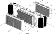
- the proposed linear drive is based on linear induction electric motors, which, in this case, are arranged in the short double-faced primary configuration in which two linear motor units are positioned against each other (08a and 08b), leaving a free gap between them for the passage of the inducted element.
- the primary is the part of the electric motor that contains the winding of the phases in the form of coils that are installed in the slots of its laminated iron core, forming the motor's poles.
- the element undergoing induction generated by the field modulation in the windings of the primary is called the secondary, and in this case, it must necessarily be constructed with conductive materials such as copper or aluminum.
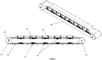
- the invention also proposes two options for this secondary , since, in the use in linear conveyors, the secondary element must allow loop movement accommodating itself on the return drums located at the head of the conveyors during curves.
- the two options are:
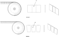
- An overlapped section secondary where the sections are justified to facilitate the flexibility of the conveyor belt and it must be overlapped to allow continuity of the active area and perform curves on the drum without deforming, as illustrated in figure 5 .
- the area seen by the primary is constant and without gaps, thus achieving greater efficiency and smooth movement.
- a disadvantage of this configuration is that the total thickness of the secondary is that of two plates, which increases the gap between the active faces of the primary of the motor.
- the second type is a trapezoidal section secondary, where the sections are justified by the flexibility of the conveyor belt and have a trapezoidal shape to allow curves on the return drums, as shown in figure 6 . Since there is no overlap of plates in this case, the thickness of the secondary is the same as that of the plate used, allowing a shorter distance between the active faces of the primary. However, due to the trapezoidal shape of the plate, there is a loss of active area when the secondary is in the region of the primary, causing lower efficiency and vibrations due to the variation between the upper and lower areas of the secondary blade.
- the proposed invention stands out from others by the use of a double-faced induction motor with an aluminum secondary in the application of linear conveyors, where no compatible examples were found in the searches for prior art.
- the activation and control of the motor units are carried out through frequency inverters that act on the current modulation in the coils of the primary, generating a traveling wave in the different motor poles.
- This traveling field in the gap region between the active faces of the primary generates induced currents on the faces of the secondary made of conductive material.
- the interaction between the fields generated by the currents of the primary and the secondary generates forces in the direction of movement of the plate train.
- Another advantage of the invention is to increase the availability of conveyors because if there is a failure in any electric motor unit, its load can be redistributed to the other motors in operation. Thus, the defective unit can be replaced without shutting down the conveyor due to no mechanical contact between the parts.
- the invention of this type of distributed drive with segmented secondary that allows accommodation on return drums also solves the problem of unidirectional movement existing in conventional conveyors with rotary motors.
- Such equipment to generate movement in two directions, required a motor assembly on both drums of the conveyor and the need to reposition tensioners or tensioning devices for flexible belts so that the conveyors always operated in traction (pulling the belt).
- conveyors can benefit from driving in both directions without the need for physical modifications to the equipment. This is because the tension in the belt is distributed, preventing the "wrinkling" of the belt.
- the linear induction motor tolerates the presence of dirt better due to the greater space between the secondary plates and the active face of the primary.
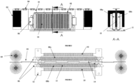
- the invention features bristle cleaners or scrapers to remove larger debris, deflectors at the entry and exit of the primary to direct the primary plates and a protective box to reduce the volume of contaminating material that may enter the primary. All this equipment is designed to facilitate the assembly and maintenance of the motor, and can be easily removed for cleaning.
- Such linear drive applies to horizontal or vertical conveyors with flexible rubber or metallic for the transport of granulated materials.
- Deflectors are strategically positioned elements to prevent misalignment of the secondary, ensuring that its plates will pass in the central region of the primary without touching the inner faces.
- This device consists of two plates positioned bilaterally like a nozzle that directs the secondary train into the primary of the motor to centralize this element and prevent possible collisions.
- the deflector material should not cause damage to the secondary plates and should be constructed to allow practical replacement when necessary.
- rollers (03) located on the top of the box (09). Their presence is necessary because the motor is positioned in the space between the rollers of the conveyor. In this region, there is the possibility of forming a "belly" or sag deformation of the conveyor belt due to the action of the transported load. This catenary curve can cause the top of the secondary (01) to collide vertically with the body of the primary or its protective box. These rollers then prevent this collision and allow continuous movement of the belt and secondary.
- the rollers should be constructed of materials that do not degrade the secondary, such as engineering plastics or composites, and equipped with bearings for rotation during contact.
- the entire length of the internal faces of the primary must be resin-coated with a fiberglass cover. This promotes protection against unwanted collisions, touches from the secondary, and also protects the motor from water, allowing it to operate in the open under rain.
- the motor Since the motor is continuously on for extended periods, it is equipped with finned aluminum heat sinks (10) promoting heat exchange by natural or forced convection depending on the ambient temperature of the operating location.
- each secondary (04) blade is done independently on the conveyor belt, allowing freedom for its elongation and not restricting the elastic behavior of the conveyor.
- longitudinal elongation is normal due to operational loads and thermal expansion during operation.
- the train of secondary plates of the motor is fixed directly to the body of the belt through screws and cannot in any way prevent the expansion or elongation of the belt, as this would result in high mechanical tension on the motor secondary, leading to its breakage.
Landscapes
- Engineering & Computer Science (AREA)
- Mechanical Engineering (AREA)
- Linear Motors (AREA)
- Non-Mechanical Conveyors (AREA)
- Structure Of Belt Conveyors (AREA)
Applications Claiming Priority (2)
| Application Number | Priority Date | Filing Date | Title |
|---|---|---|---|
| BR102021021562-3A BR102021021562A2 (pt) | 2021-10-27 | 2021-10-27 | Acionamento linear para equipamento de transporte contínuo de materiais a granel |
| PCT/BR2022/050399 WO2023070183A1 (pt) | 2021-10-27 | 2022-10-17 | Acionamento linear para equipamento de transporte contínuo de materiais a granel |
Publications (2)
| Publication Number | Publication Date |
|---|---|
| EP4424618A1 true EP4424618A1 (de) | 2024-09-04 |
| EP4424618A8 EP4424618A8 (de) | 2024-12-25 |
Family
ID=86160214
Family Applications (1)
| Application Number | Title | Priority Date | Filing Date |
|---|---|---|---|
| EP22884811.5A Pending EP4424618A1 (de) | 2021-10-27 | 2022-10-17 | Linearantrieb für eine kontinuierliche schüttgutfördervorrichtung |
Country Status (6)
| Country | Link |
|---|---|
| US (1) | US20240409319A1 (de) |
| EP (1) | EP4424618A1 (de) |
| CN (1) | CN118176155A (de) |
| AU (1) | AU2022375209A1 (de) |
| BR (1) | BR102021021562A2 (de) |
| WO (1) | WO2023070183A1 (de) |
Family Cites Families (18)
| Publication number | Priority date | Publication date | Assignee | Title |
|---|---|---|---|---|
| US3788447A (en) * | 1972-07-03 | 1974-01-29 | Fmc Corp | Linear motor conveyor |
| GB1442127A (en) * | 1972-11-16 | 1976-07-07 | British Steel Corp | Conveyancing systems |
| ZA907711B (en) | 1989-11-01 | 1992-01-29 | Lewin Heinz Ulrich | Conveyor belt |
| US5172803A (en) | 1989-11-01 | 1992-12-22 | Lewin Heinz Ulrich | Conveyor belt with built-in magnetic-motor linear drive |
| JPH09183518A (ja) * | 1996-01-04 | 1997-07-15 | Tsubakimoto Chain Co | 同期型リニアモータ駆動式スラットコンベヤ |
| JP2004043132A (ja) * | 2002-07-12 | 2004-02-12 | Ishikawajima Transport Machinery Co Ltd | 搬送装置 |
| DE102005019036A1 (de) * | 2005-04-23 | 2006-10-26 | Ima Klessmann Gmbh Holzbearbeitungssysteme | Werkstücktransportvorrichtung mit zumindest einer endlos umlaufenden Kette |
| WO2008125122A1 (en) | 2007-04-16 | 2008-10-23 | Fki Logistex A/S | Sorting system with linear synchronous motor drive |
| DE102009048822A1 (de) * | 2009-10-09 | 2011-04-14 | Siemens Aktiengesellschaft | Beförderungssystem mit elektromagnetischer Bremse |
| DE102011016039A1 (de) | 2011-04-04 | 2012-03-08 | Jan-Peter Jastrzembski | Antrieb eines Förderers durch einen Linearmotor |
| DE102011075176A1 (de) | 2011-05-03 | 2012-11-08 | Robert Bosch Gmbh | Verfahren zum Betreiben eines elektromagnetischen Transfersystems und Transfersystem |
| DE102011056249A1 (de) | 2011-12-09 | 2013-06-13 | Thyssenkrupp Transrapid Gmbh | Linear-Synchronmotor |
| JP5594308B2 (ja) | 2012-03-08 | 2014-09-24 | 株式会社安川電機 | リニアモータの電機子、リニアモータ、および電機子の製造方法 |
| BR102012015252A2 (pt) | 2012-06-20 | 2014-07-29 | Whirlpool Sa | Método de acionamento elétrico de motor linear |
| ES3040606T3 (en) * | 2016-10-05 | 2025-11-03 | Laitram Llc | Linear-motor conveyor system |
| IT201900017441A1 (it) * | 2019-09-27 | 2021-03-27 | Ocm S P A | Sistema di trasporto |
| US20230026825A1 (en) * | 2021-07-13 | 2023-01-26 | Redwire Space, Inc. | Distributed Drive Systems and Methods of Use Thereof |
| EP4421007A1 (de) * | 2023-02-24 | 2024-08-28 | Robert Bosch GmbH | Gleismodul und trägermodul für ein linearmotorfördersystem sowie linearmotorfördersystem |
-
2021
- 2021-10-27 BR BR102021021562-3A patent/BR102021021562A2/pt unknown
-
2022
- 2022-10-17 EP EP22884811.5A patent/EP4424618A1/de active Pending
- 2022-10-17 WO PCT/BR2022/050399 patent/WO2023070183A1/pt not_active Ceased
- 2022-10-17 AU AU2022375209A patent/AU2022375209A1/en active Pending
- 2022-10-17 CN CN202280072700.4A patent/CN118176155A/zh active Pending
- 2022-10-17 US US18/704,525 patent/US20240409319A1/en active Pending
Also Published As
| Publication number | Publication date |
|---|---|
| EP4424618A8 (de) | 2024-12-25 |
| WO2023070183A1 (pt) | 2023-05-04 |
| CN118176155A (zh) | 2024-06-11 |
| AU2022375209A1 (en) | 2024-05-16 |
| US20240409319A1 (en) | 2024-12-12 |
| BR102021021562A2 (pt) | 2023-05-09 |
Similar Documents
| Publication | Publication Date | Title |
|---|---|---|
| EP4404447A1 (de) | Von einem linearen induktionsmotor angetriebenes förderband mit einem doppelseitigen primärteil und einem langen segmentierten sekundärteil | |
| KR101049222B1 (ko) | 수직형 리니어모터를 이용한 자기부상 반송장치 | |
| KR101197257B1 (ko) | 정지 성능이 향상된 자기부상 이송 시스템 | |
| KR101049221B1 (ko) | 리니어 인덕션 모터를 이용한 자기부상 반송장치 | |
| CN104272568B (zh) | 直线同步电动机 | |
| US20120193172A1 (en) | Conveyor system comprising an electromagnetic brake | |
| CN101689797A (zh) | 具有线性同步马达驱动的分类系统 | |
| KR20130063901A (ko) | 무동력 트레이를 갖는 자기부상 반송장치 | |
| KR101101917B1 (ko) | 자기부상 반송 장치 | |
| US8217538B2 (en) | Linear motor having a slidable element | |
| JP7464542B2 (ja) | 長固定子リニアモーターのための運搬装置 | |
| KR20080073005A (ko) | 최적 공극제어 선형전동기 및 비접촉 급전시스템을 이용한철도차량시스템 | |
| KR100840927B1 (ko) | 선형전동기 및 비접촉 급전시스템을 이용한 철도차량시스템 | |
| EP4424618A1 (de) | Linearantrieb für eine kontinuierliche schüttgutfördervorrichtung | |
| US11459178B2 (en) | Sorting installation, latching apparatus and transport unit | |
| US11336165B2 (en) | Curvilinear motor | |
| KR20120059931A (ko) | 곡선 주행 성능이 향상된 자기부상 이송 시스템 | |
| JP5252384B2 (ja) | 乗客コンベア | |
| OA21681A (en) | Linear drive for continuous bulk material conveying device. | |
| Yoshida et al. | Proposal of a novel transfer device using a linear motor in parallel synchronous operation | |
| OA21622A (en) | Conveyor for granular material driven by linear induction motor with double-sided primary and long-sectioned secondary for belt alignment. | |
| CN117775740A (zh) | 一种电磁驱动的多滑块独立控制的环形轨道输送系统 | |
| JP2006044936A (ja) | リニアモータ駆動チェーン | |
| EP4591423A1 (de) | Ankerschutz für elektromagnetischen linearantrieb | |
| JP2006213462A (ja) | 駆動式搬送チェーン |
Legal Events
| Date | Code | Title | Description |
|---|---|---|---|
| STAA | Information on the status of an ep patent application or granted ep patent |
Free format text: STATUS: THE INTERNATIONAL PUBLICATION HAS BEEN MADE |
|
| PUAI | Public reference made under article 153(3) epc to a published international application that has entered the european phase |
Free format text: ORIGINAL CODE: 0009012 |
|
| STAA | Information on the status of an ep patent application or granted ep patent |
Free format text: STATUS: REQUEST FOR EXAMINATION WAS MADE |
|
| 17P | Request for examination filed |
Effective date: 20240416 |
|
| AK | Designated contracting states |
Kind code of ref document: A1 Designated state(s): AL AT BE BG CH CY CZ DE DK EE ES FI FR GB GR HR HU IE IS IT LI LT LU LV MC ME MK MT NL NO PL PT RO RS SE SI SK SM TR |
|
| RAP3 | Party data changed (applicant data changed or rights of an application transferred) |
Owner name: TRAD, FREDERICO Owner name: HAKA GROUPS PARTICIPACOES DE NEGOCIOS S/A |
|
| DAV | Request for validation of the european patent (deleted) | ||
| DAX | Request for extension of the european patent (deleted) |