EP4423822B1 - Neues anodenmaterial in lithium- und natriumbatterien - Google Patents
Neues anodenmaterial in lithium- und natriumbatterien Download PDFInfo
- Publication number
- EP4423822B1 EP4423822B1 EP22812472.3A EP22812472A EP4423822B1 EP 4423822 B1 EP4423822 B1 EP 4423822B1 EP 22812472 A EP22812472 A EP 22812472A EP 4423822 B1 EP4423822 B1 EP 4423822B1
- Authority
- EP
- European Patent Office
- Prior art keywords
- carbon
- lithium
- networks
- anode
- sodium
- Prior art date
- Legal status (The legal status is an assumption and is not a legal conclusion. Google has not performed a legal analysis and makes no representation as to the accuracy of the status listed.)
- Active
Links
Images


Classifications
-
- H—ELECTRICITY
- H01—ELECTRIC ELEMENTS
- H01M—PROCESSES OR MEANS, e.g. BATTERIES, FOR THE DIRECT CONVERSION OF CHEMICAL ENERGY INTO ELECTRICAL ENERGY
- H01M10/00—Secondary cells; Manufacture thereof
- H01M10/05—Accumulators with non-aqueous electrolyte
- H01M10/052—Li-accumulators
- H01M10/0525—Rocking-chair batteries, i.e. batteries with lithium insertion or intercalation in both electrodes; Lithium-ion batteries
-
- H—ELECTRICITY
- H01—ELECTRIC ELEMENTS
- H01M—PROCESSES OR MEANS, e.g. BATTERIES, FOR THE DIRECT CONVERSION OF CHEMICAL ENERGY INTO ELECTRICAL ENERGY
- H01M10/00—Secondary cells; Manufacture thereof
- H01M10/05—Accumulators with non-aqueous electrolyte
- H01M10/054—Accumulators with insertion or intercalation of metals other than lithium, e.g. with magnesium or aluminium
-
- H—ELECTRICITY
- H01—ELECTRIC ELEMENTS
- H01M—PROCESSES OR MEANS, e.g. BATTERIES, FOR THE DIRECT CONVERSION OF CHEMICAL ENERGY INTO ELECTRICAL ENERGY
- H01M4/00—Electrodes
- H01M4/02—Electrodes composed of, or comprising, active material
- H01M4/13—Electrodes for accumulators with non-aqueous electrolyte, e.g. for lithium-accumulators; Processes of manufacture thereof
- H01M4/133—Electrodes based on carbonaceous material, e.g. graphite-intercalation compounds or CFx
-
- H—ELECTRICITY
- H01—ELECTRIC ELEMENTS
- H01M—PROCESSES OR MEANS, e.g. BATTERIES, FOR THE DIRECT CONVERSION OF CHEMICAL ENERGY INTO ELECTRICAL ENERGY
- H01M4/00—Electrodes
- H01M4/02—Electrodes composed of, or comprising, active material
- H01M4/13—Electrodes for accumulators with non-aqueous electrolyte, e.g. for lithium-accumulators; Processes of manufacture thereof
- H01M4/139—Processes of manufacture
- H01M4/1393—Processes of manufacture of electrodes based on carbonaceous material, e.g. graphite-intercalation compounds or CFx
-
- H—ELECTRICITY
- H01—ELECTRIC ELEMENTS
- H01M—PROCESSES OR MEANS, e.g. BATTERIES, FOR THE DIRECT CONVERSION OF CHEMICAL ENERGY INTO ELECTRICAL ENERGY
- H01M4/00—Electrodes
- H01M4/02—Electrodes composed of, or comprising, active material
- H01M4/36—Selection of substances as active materials, active masses, active liquids
- H01M4/38—Selection of substances as active materials, active masses, active liquids of elements or alloys
- H01M4/386—Silicon or alloys based on silicon
-
- H—ELECTRICITY
- H01—ELECTRIC ELEMENTS
- H01M—PROCESSES OR MEANS, e.g. BATTERIES, FOR THE DIRECT CONVERSION OF CHEMICAL ENERGY INTO ELECTRICAL ENERGY
- H01M4/00—Electrodes
- H01M4/02—Electrodes composed of, or comprising, active material
- H01M4/36—Selection of substances as active materials, active masses, active liquids
- H01M4/58—Selection of substances as active materials, active masses, active liquids of inorganic compounds other than oxides or hydroxides, e.g. sulfides, selenides, tellurides, halogenides or LiCoFy; of polyanionic structures, e.g. phosphates, silicates or borates
- H01M4/583—Carbonaceous material, e.g. graphite-intercalation compounds or CFx
- H01M4/587—Carbonaceous material, e.g. graphite-intercalation compounds or CFx for inserting or intercalating light metals
-
- H—ELECTRICITY
- H01—ELECTRIC ELEMENTS
- H01M—PROCESSES OR MEANS, e.g. BATTERIES, FOR THE DIRECT CONVERSION OF CHEMICAL ENERGY INTO ELECTRICAL ENERGY
- H01M4/00—Electrodes
- H01M4/02—Electrodes composed of, or comprising, active material
- H01M2004/026—Electrodes composed of, or comprising, active material characterised by the polarity
- H01M2004/027—Negative electrodes
-
- Y—GENERAL TAGGING OF NEW TECHNOLOGICAL DEVELOPMENTS; GENERAL TAGGING OF CROSS-SECTIONAL TECHNOLOGIES SPANNING OVER SEVERAL SECTIONS OF THE IPC; TECHNICAL SUBJECTS COVERED BY FORMER USPC CROSS-REFERENCE ART COLLECTIONS [XRACs] AND DIGESTS
- Y02—TECHNOLOGIES OR APPLICATIONS FOR MITIGATION OR ADAPTATION AGAINST CLIMATE CHANGE
- Y02E—REDUCTION OF GREENHOUSE GAS [GHG] EMISSIONS, RELATED TO ENERGY GENERATION, TRANSMISSION OR DISTRIBUTION
- Y02E60/00—Enabling technologies; Technologies with a potential or indirect contribution to GHG emissions mitigation
- Y02E60/10—Energy storage using batteries
Definitions
- the present invention is in the field of lithium and sodium batteries. More particularly, the present invention relates to improved anodes in rechargeable lithium and sodium batteries.
- the invention preferably relates to sodium-ion and lithium-ion batteries, most preferably lithium-ion batteries.
- lithium is the first choice for negative electrode material.
- the reason lies in the specific capacity for lithium which is much higher than that of for example zinc and lead. It is the lightest, most electropositive metal with high energy and power density.
- the demand for lithium batteries or 'lithium secondary batteries' keeps increasing, especially as power sources for portable electronic devices such as smartphones or laptops (including their liquid crystal display (LCD) or organic light emitting diodes (OLED)), power plant energy storage (i.e. from surplus wind and solar renewable energy), Uninterruptible Power Supply (UPS) and as power sources for driving motors of electric and hybrid vehicles.
- LCD liquid crystal display
- OLED organic light emitting diodes
- UPS Uninterruptible Power Supply
- lithium batteries are the most widely used power batteries, the production of lithium batteries faces great challenges, such as an increasing shortage of lithium resources, the rising price of upstream materials and a low recycling rate.
- sodium batteries making use of an intercalation process of sodium ions between a positive electrode and a negative electrode, make a solid alternative choice.
- the advantages of sodium batteries are that the reserve of sodium resources is far more abundant than that of lithium, the distribution is more extensive, and the cost of sodium is far lower than that of lithium; for these reasons, sodium batteries have the potential to replace lithium batteries, insofar as issues such as their low coulombic efficiency and poor rate capability are overcome or reduced to satisfactory proportions.
- Lithium and sodium batteries are typically composed of four major components: cathode, anode, separator and electrolyte.
- the electrolyte serves as a conductive medium through which lithium ions can be transported to and from the electrodes.
- the electrolyte can be either solid-state or liquid.
- a 'lithium battery' or 'sodium battery' includes both solid state (with solid electrolyte) and liquid state (with liquid electrolyte) batteries.
- the terms 'lithium-ion battery' and sodium-ion battery' are reserved for battery technology with a liquid electrolyte.
- the cathode of lithium batteries generally comprises a Lithium-Metal-Oxide (e.g. lithium cobalt oxide (LiCoO 2 )).
- Lithium-Metal-Oxide e.g. lithium cobalt oxide (LiCoO 2 )
- the materials commonly used as active materials in the anode of lithium batteries are intercalation compounds, metal alloys and conversion compounds (transition-metal oxides).
- the most common of the intercalation compounds used in the anode of a lithium battery is graphite.
- Another common compound used in the anode of lithium batteries is silicon or silicon-based compounds.
- silicon materials have high specific capacity compared to graphite. All in all, hitherto graphite remains the dominant intercalation anode material in commercial lithium batteries; this is because the performance of graphite is safe and provides sufficient energy density for many portable power applications, as well as low working potential, low cost and good cycle life.
- a battery with a graphite anode usually has moderate power density due to the relatively slow diffusion rate of lithium ion into carbon materials (between 10 -12 and 10 -6 cm 2 /s); this feature, together with a suboptimal electron conductivity, results in charge/discharge rates of graphite alone being not optimal, and thus in long charging and discharging times of the battery.
- conductive additives are traditionally added to anode active materials to improve the electron conductivity of the anode ( Roselin et al., "Recent Advances and Perspectives of Carbon-Based Nanostructures as Anode Materials for Li-ion Batteries”. Materials 2019, 12, 1229 ). These additives construct a conductive percolation network to increase and keep the electronic conductivity of electrode, enabling it charge and discharge faster. In addition, conductive additives absorb and retain electrolyte, allowing an intimate contact between the lithium or sodium ions and active materials.
- the conductive additive for lithium and sodium batteries is commonly a carbon nanomaterial selected from conductive carbon black, Super P, acetylene black, carbon nanofibers, and carbon nanotubes, all presenting low weight, high chemical inertia and high specific surface area ( Zhang Q et al., "Carbon nanomaterials used as conductive additives in lithium ion batteries", Recent Pat Nanotechnol. 2010 Jun;4(2):100-10 ).
- Conductive carbon black has been used as a conductive additive to the electrochemically active material in the anode or cathode, to improve the electron conductivity and thus the charge and discharge rates of the batteries.
- carbon black has been tested as the active material in the anode.
- WO1998/038685 discloses a rechargeable battery with an anode comprising thermal carbon black of average particle size greater than 100 nm, in particular 85-95% thermal carbon black, about 0-10% conductive black and about 5% binder.
- thermal carbon black presents a low crystallinity, which derives into a lower electrical conductivity, and higher brittleness and a broad particle size distribution of its globular particles, which results in non-homogenous properties between batches. Therefore, thermal carbon black is not suitable for either manufacturing or day-to-day use physical stability in lithium or sodium batteries.
- carbon black has not found any commercial application in lithium or sodium batteries other than in the form of a conductive additive.
- Sodium batteries present their very own challenges. For instance, since a sodium ion (1.02 ⁇ ) is 55% larger than lithium ion (0.69 ⁇ ), it is more difficult to accommodate sodium ions in anodes reversibly.
- graphite materials commercially used as anodes in lithium batteries could not achieve acceptable performances on sodium batteries, because graphite anodes that have been used up to now in sodium batteries absorb too little sodium, which results in sodium batteries being less powerful because they inevitably lose energy storage density due to a lower cell voltage.
- Alternative anode materials such as red phosphorus (P) have been used to overcome the limitations of graphite as an anode material.
- carbon nanofibres-comprising carbon networks can be beneficially used as an active anode material in lithium or sodium batteries instead of currently used active anode materials, to the extent that the above goals in the art can be fulfilled; in particular, a high capacity, high lifetime (stability over extended cycling), high charge and discharge rate, all while having physical properties that enable a safe manufacturing and use.
- the inventors found that the anodes comprising the carbon nanofibres-comprising carbon networks according to the invention as an active anode material can contribute to lithium or sodium battery capacity through a different intercalation of lithium or sodium ions. Lifetime (stability over extended cycling) can be improved by improving electron conductivity; reference is made to Table 4 herein. Because the electron conductivity of the carbon nanofibres-comprising carbon networks according to the invention is high (for instance compared to that of graphite), the reversibility of the charge/discharge process is enhanced when using the carbon nanofibres-comprising carbon networks according to the invention as anode material.
- the inventors believe that these advantageous properties could be attributed to the networks' inherent electron conductivity and open pore structure due to their crystallinity, accessible porosity, filaments length-to-diameter ratio and their d-spacing, which facilitates the diffusion of lithium or sodium ions.
- the graphitic crystallites in the carbon nanofibres-comprising carbon networks according to the invention are arranged in nanosized filaments, which greatly reduces the diffusion path length of lithium or sodium ions during intercalation, as the distance for lithium or sodium ions to move from the outside to the center of the carbon material is shorter. Overall, these improved features result in an improved conductivity route.
- the carbon nanofibres-comprising carbon networks according to the invention represents a micron-sized nanostructured material comprising filaments which are highly conductive and 50 nm thick, while other anode materials such as graphite present particle dimensions in the ⁇ m scale. These nanofilaments facilitate the conveyance of electrons and the intercalation of lithium or sodium ions so their diffusion time is reduced.
- the inventors found that, while the use of the carbon nanofibres-comprising carbon networks according to the invention as anode material in a battery presents high capacity and long lifetime values comparable to those of common active anode materials such as graphite. This allows for high charge / discharge rates, thus providing for batteries with a reduced charging time. In particular, it allows the manufacturing of batteries charging in minutes (i.e. 6 minutes) instead of hours.
- these porous carbon networks form an intraparticle porous network wherein the carbon nanofibers are interconnected to other carbon nanofibers in the network by chemical bonds via junctions, wherein the pores in the network have an intraparticle pore diameter size of 5-150 nm using Mercury Intrusion Porosimetry according to ASTM D4404-10, and the carbon nanofibers have an average aspect ratio of fibre length-to-thickness of at least 2, preferably having a d-spacing of 0.340-0.5 nm, more preferably of 0.35-0.45 nm, even more preferably of 0.355-0.375 nm.
- this d-spacing is higher than that of other anode active materials such as graphite (0.335 nm), which facilitates the intercalation of lithium or sodium ions. Because of their higher volume, this higher d-spacing is particularly beneficial to the intercalation of sodium ions in sodium batteries.
- the invention thus pertains to the use of carbon nanofibres-comprising carbon networks as active components in the anode of lithium or sodium batteries, to the anode comprising these carbon nanofibres-comprising carbon networks and to the lithium or sodium batteries comprising these anodes. While the invention in broadest sense also relates to solid state lithium and sodium batteries, the invention preferably relates to lithium-ion and sodium-ion batteries, more preferably lithium-ion batteries
- a battery is a device that changes chemical energy into electric energy by means of electrochemical oxidation-reduction reaction (redox) reaction.
- the essential electrochemical unit achieving such energy change is known as a "cell".
- a battery contains a group of interconnected cells. The number of cells utilized relies upon the desired capacity and voltage for a specific application. A few electrochemical cells are associated with the arrangement as well as in parallel to acquire a lithium-ion battery of indicated voltage and capacity.
- Each cell contains the following parts: a negative terminal (anode), where electrochemical oxidation happens during discharge; a positive terminal (cathode), where electrochemical decrease happens; an electrolyte, which encourages the transportations of ions from one electrode to another electrode; a separator, which gives electronic segregation between the electrodes; and a casing, which contains the other cell parts.
- Lithium-ion cells use a solid reductant as an anode and a solid oxidant as a cathode.
- the cathode materials used in most of the commercial Li-ion batteries are LiCoO 2 or LiNiO 2 and the anode materials are carbonaceous.
- the cathode material releases Li ions to the electrolyte and electrons are removed from the cathode by applying an external field and are then transferred to the anode.
- the charge-compensating Li ions are attracted by the negative electrode and then inserted into it.
- the reverse reaction occurs. That is, the anode supplies intercalated Li ions into the electrolyte and provides electrons to the external circuit.
- the Li ions intercalate from the electrolyte and satisfy the charge of electrons from an external circuit.
- Common carbon anode materials are graphite or coke-type or both combined; common cathode materials include LiMn 2 O 4 , LiCoO 2 , and LiNiO 2 .
- the electrolyte can be either solid or liquid.
- the liquid electrolyte is usually a non-aqueous solution of Li salts and various solvents including ethers, esters, and carbonates.
- the invention concerns secondary or rechargeable batteries, and particularly provides for the carbon source (at the anode) in the above redox reaction (2).
- a 'lithium battery' or 'sodium battery' includes both solid state (with solid electrolyte) and liquid state (with liquid electrolyte) batteries.
- the terms 'lithium-ion battery' and 'sodium-ion battery' are reserved for battery technology with a liquid electrolyte.
- the invention can be described as the use of porous, chemically interconnected, carbon nanofibres-comprising carbon networks (i.e. porous carbon networks which comprise chemically interconnected carbon-nanofibres) as an active material in the anode of a lithium or a sodium battery.
- an "active material in the anode” is to be understood as a material in the anode that actively participates in the electrochemical charge and/or discharge reaction, providing the carbon-based material for the Li-ion intercalation/de-intercalation during charging and discharging, respectively.
- the invention pertains to an anode for a lithium or sodium battery comprising porous, chemically interconnected, carbon nanofibres-comprising carbon networks (i.e. porous carbon networks which comprise chemically interconnected carbon-nanofibres).
- the anode essentially consists of the networks according to the invention, preferably at least 80 wt%, more preferably at least 90 wt%, most preferably 95 - 100 % of the weight of the anode.
- the invention also pertains to an anode for a lithium or a sodium battery comprising porous, chemically interconnected, carbon nanofibres-comprising carbon networks in an amount of 10 - 100 wt%, preferably more than 10 wt% and less than 100 wt%, more preferably 40 - 95 wt%, even more preferably 50- 90 wt% of the anode, the remainder preferably being additional anode materials capable of intercalation and release of lithium or sodium ions.
- the additional active material is silicon or graphite. If the additional active material in the anode is silicon, a silicon-based compound (SiO 2 ), or a combination thereof, silicon, the silicon-based compound (SiO 2 ), or combination thereof are mixed with the carbon nanofibres-comprising carbon networks of the invention in the anode or the carbon nanofibres-comprising carbon networks of the invention are coated with silicon, a silicon-based compound (SiO 2 ), or combination thereof.
- the additional active material in the anode is an oxide for intercalation-type anodes such as TiO 2 , oxide for conversion-type anode such as Fe 2 O 3 , oxide for conversion-alloying-type anode such as Sn x O 2 and Sb 2 O 3 or "hard carbon", a disordered carbon material consisting of a non-graphitizable, non-crystalline and amorphous carbon structure.
- the active material in the cathode is a lithium or sodium metal, alkali metal and/or lithium or sodium metal oxide.
- the active material is LiCoO 2 or LiMn 2 O 4 .
- the active material in the cathode is lithium iron phosphate (LiFePO 4 ).
- the active material in the cathode is an O3-type layered metal oxide such as NaFeO 2 , P2-type layered metal oxide such as Na 0.6 MnO 2 , biphase layered metal oxide such as Na 0.78 Ni 0.2 Fe 0.38 Mn 0.42 O 2 or an oxide with anionic redox capability.
- the electrolyte of the lithium or sodium batteries may be liquid or solid-state.
- the liquid electrolyte may comprise an organic solvent and a salt of an alkali metal, preferably a lithium or sodium salt for lithium-ion and sodium-ion batteries, respectively.
- the liquid electrolyte of the lithium battery may comprise an organic solvent and a salt of an alkali metal, preferably a lithium salt.
- the liquid electrolyte of the sodium battery may comprise an organic solvent and a sodium salt.
- the organic solvent may be one or more of Ethylene Carbonate (EC), Propylene Carbonate (PC), Ethyl Methyl Carbonate (EMC), and diethyl carbonate (DEC);
- the sodium salt may be NaPF 6 , NaClO 4 .
- the electrolyte of the lithium or sodium batteries may also be solid-state and comprise inorganic-ceramic/glass-ceramic, organic polymer and/or ceramic-polymer composite electrolytes.
- the electrolyte is a liquid electrolyte.
- the separator of the lithium or sodium battery may comprise one or more of glass fiber, nonwoven fabric, polyethylene, polypropylene, and polyvinylidene fluoride.
- the separator of the lithium or sodium battery is polypropylene.
- the anode for a lithium or sodium battery according to the invention may comprise conventional additives (non-active materials) on top of the porous, chemically interconnected, carbon nanofibres-comprising carbon networks to further improve the electrochemical performance of the lithium or sodium batteries according to the invention.
- these additives can be added to construct a conductive percolation network to increase and keep the electronic conductivity of electrode, enabling it to charge and discharge faster, and to absorb and retain electrolyte, allowing an intimate contact between the lithium or sodium ions and active materials. It is considered within the skilled person ambit to select suitable conductive additives available in the art.
- Binder materials are responsible for holding the active material particles within the electrode of a lithium or sodium battery together to maintain a strong connection between the electrode and the contacts. These binding materials are normally inert and have an important role in the manufacturability of the battery.
- the anode for a lithium or sodium battery according to the invention may comprise 0.1-10 wt%, preferably 2-8 wt%, most preferably 4-6 wt% of a binder such as Styrene Butadiene Rubber (SBR), water-based acrylic resin (water-based acrylic resin), carboxymethyl cellulose (CMC), polyvinylidene fluoride (PVDF), Polytetrafluoroethylene (PTFE), ethylene-vinyl acetate copolymer (EVA), and polyvinyl alcohol (PVA).
- SBR Styrene Butadiene Rubber
- VDF polyvinylidene fluoride
- PTFE Polytetrafluoroethylene
- EVA ethylene-vinyl acetate copolymer
- the anode for lithium or sodium batteries or lithium or sodium batteries of the invention are particularly suitable for use in the manufacture of battery-powered electric devices.
- the invention extends to battery-powered electric devices comprising at least one anode for lithium or sodium batteries or at least one lithium or sodium battery comprising the porous, chemically interconnected, carbon nanofibres-comprising carbon networks according to the invention.
- a battery-powered electric device may be a smartphone, laptop, digital cameras and camcorders, medical and communication systems, as Uninterruptible Power Supply (UPS), as power plant energy storage (i.e. from surplus wind and solar renewable energy) and electric and/or hybrid vehicles.
- UPS Uninterruptible Power Supply
- the anode for lithium or sodium batteries or lithium or sodium batteries according to the invention are used in Uninterruptible Power Supply (UPS) systems, portable consumer electronics and electric and/or hybrid vehicles.
- UPS Uninterruptible Power Supply
- portable consumer electronics portable consumer electronics and electric and/or hybrid vehicles.
- porous, chemically interconnected carbon nanofibre-comprising carbon networks or porous carbon networks comprising chemically interconnected carbon nanofibers are preferably characterized as follows:
- a porous network refers to a 3-dimensional structure that allows fluids or gasses to pass through.
- a porous network may also be denoted as a porous medium or a porous material.
- a porous crystalline carbon network according to the invention (or a porous carbon network particle of the invention) can be seen as a big molecule, wherein the carbon atoms inherently are covalently interconnected. It is hereby understood that a porous carbon network particle is a particle with chemically interconnected (i.e.
- intraparticle porosity may also be denoted as intramolecular porosity as the carbon network particle according to the invention can be seen as a big molecule, wherein the pores are embedded.
- intraparticle porosity and intramolecular porosity have the same meaning in the current text and may be used interchangeably.
- the porous, chemically interconnected, carbon nanofibres-comprising carbon networks are non-fused, intraparticle porous, chemically interconnected, crystalline carbon nanofibres-comprising carbon networks, having intraparticle porosity.
- the benefit of having a crystalline network with intraparticle porosity over a(n amorphous) network with interparticle porosity is that the first are more robust and more resilient against crushing and breaking when force is applied.
- carbon black consists of aggregates or agglomerates of spherical particles that may form a 3-dimensional structure, where spheres are fused with amorphous connections with weaker porosity.
- the interparticle pores are weaker due to the particle-particle interface and tend to collapse.
- Intraparticle pores are strong due to the covalently crystalline aligned bonded structure surrounding them and can withstand high forces and pressures without collapsing.
- conventional carbon black consisting of aggregates or agglomerates of spherical particles that may form a 3-dimensional structure, where spheres are fused with amorphous connection between the individual particles (not chemically 'interconnected').
- intraparticle porosity refers to the situation wherein the carbon atoms surrounding the pores are covalently connected in crystalline form, wherein interparticle porosity refers to pores residing between particles which are physically aggregated, agglomerated, or have amorphous connections.
- Intraparticle pore volume may be characterized in terms of Mercury Intrusion Porosimetry (ASTM D4404-10) or Nitrogen Absorption method (ISO 9277:10).
- the pore volume of the porous carbon networks according to the invention is 0.05- 5 cm 3 /g, preferably 0.1- 4 cm 3 /g, more preferably 0.3 - 3.5 cm 3 /g and most preferably 0.5 - 3 cm 3 /g as measured using Mercury Intrusion Porosimetry (ASTM D4404-10).
- the carbon nanofibres-comprising carbon networks may be characterized having an intraparticle pore diameter size as measured using Mercury Intrusion Porosimetry (ASTM D4404-10) of 5 - 200 nm, preferably 10 - 150 nm, and most preferably of 20 - 130 nm.
- the networks may have an interparticle pore diameter of 10 - 500 ⁇ m, more preferably 80 - 400 ⁇ m.
- the porous networks are preferably characterized by a d-spacing of 0.34-0.5 nm, more preferably of 0.35-0.45 nm, even more preferably of 0.355-0.375 nm.
- d-spacing is measured according to XRD.
- this d-spacing facilitates the intercalation of lithium or sodium ions. Because of their higher volume, this is particularly beneficial to the intercalation of sodium ions in sodium batteries.
- the term chemically interconnected in porous, chemically interconnected, carbon nanofibres-comprising carbon networks implies that the carbon-nanofibres are interconnected to other carbon-nanofibres by chemical bonds. It is also understood that a chemical bond is a synonym for a molecular or a covalent bond. Typically those places where the carbon-nanofibres are connected are denoted as junctions or junctions of fibres, which may thus be conveniently addressed as 'covalent junctions' These terms are used interchangeable in this text.
- the junctions are formed by covalently connected carbon atoms. It furthermore follows that the length of a fibre is defined as the distance between junctions which are connected by fibrous carbon material.
- At least part of the fibres in the carbon nanofibres-comprising carbon networks of the invention are crystalline carbon nanofibres.
- Preferably at least 20 wt.% of the carbon in the carbon networks in the invention is crystalline, more preferably at least 40 wt.%, even more preferably at least 60 wt.%, even more preferably at least 80 wt.% and most preferably at least 90 wt.%.
- the amount of crystalline carbon is 20-90 wt.%, more preferably 30-70 wt.%, and more preferably 40-50 wt.% compared to the total carbon in the carbon networks of the invention.
- 'crystalline' has its usual meaning and refers to a degree of structural order in a material.
- the carbon atoms in the nanofibres are to some extent arranged in a regular, periodic manner.
- the areas or volumes which are crystalline can be denoted as crystallites.
- a carbon crystallite is hence an individual carbon crystal.
- a measure for the size of the carbon crystallites is the stacking height of graphitic layers.
- Standard ASTM grades of carbon black have a stacking height of the graphitic layers within these crystallites ranging from 11-13 ⁇ (angstroms).
- the carbon nanofibres-comprising carbon networks of the invention preferably have a stacking height of at least 15 ⁇ (angstroms), preferably at least 16 ⁇ , more preferably at least 17 ⁇ ,even more preferably at least 18 ⁇ ,even more preferably at least 19 ⁇ and still more preferably at least 20 ⁇ . If needed the carbon networks with crystallites as large as 100 ⁇ (angstroms) can be produced.
- the carbon networks of the invention have a stacking height of 15 - 100 ⁇ (angstroms), more preferably of up to 80 ⁇ ,even more preferably of up to 60 ⁇ ,even more preferably of up to 40 ⁇ ,still more preferably of up to 30 ⁇ . It is therefore understood that the stacking height of graphitic layers within crystallites in the carbon networks of the invention is 15-90 ⁇ (angstroms), more preferably 16-70 ⁇ ,even more preferably 17-50 ⁇ ,still more preferably 18-30 ⁇ and most preferably up to 25 ⁇ .
- the porous, chemically interconnected, carbon nanofibre-comprising carbon networks may be defined as having chemically interconnected carbon nanofibres, wherein carbon nanofibres are interconnected via junction parts, wherein several (typically 3 or more, preferably at least 10 or more) nanofibres are covalently joined. Said carbon nanofibres are those parts of the network between junctions.
- the fibres typically are elongated bodies which are solid (i.e. non-hollow), preferably having an average diameter or thickness of 1 - 500 nm, preferably of 5 - 350 nm, more preferably up to 100 nm, in one embodiment 10 - 100 nm, compared to the average particle size of 10 - 400 nm for carbon black particles.
- the average fibre length (i.e. the average distance between two junctions) is preferably in the range of 30 - 10,000 nm, more preferably 50 - 5,000 nm, more preferably 100 - 5,000 nm, more preferably at least 200 - 5,000 nm, as for instance can be determined using SEM.
- the nanofibres or structures may preferably be described in terms of an average aspect ratio of fibre length-to-thickness of at least 2, preferably at least 3, more preferably at least 4, and most preferably at least 5, preferably at most below 50; in sharp contrast with the amorphous (physically associated) aggregates formed from spherical particles obtained through conventional carbon black manufacturing.
- the average aspect ratio of fibre length-to-thickness can be determined for instance using SEM.
- the carbon nanofibres structures may be defined as carbon networks formed by chemically interconnected (covalently bonded) carbon nanofibres.
- Said carbon networks have a 3-dimensional configuration wherein there is an opening between the carbon nanofibres (the intraparticle porosity, see above) that is accessible to a continuous phase, which may be a liquid - such as a solvent or an aqueous phase -, a gas or any other phase.
- Said carbon networks are at least 0.5 ⁇ m in diameter, preferably at least 1 ⁇ m in diameter, preferably at least 5 ⁇ m in diameter, more preferably at least 10 ⁇ m in diameter, even more preferably at least 20 ⁇ m in diameter and most preferably at least 25 ⁇ m in all dimensions.
- said carbon networks are at least 1 ⁇ m in diameter in 2 dimensions and at least 5 ⁇ m in diameter, preferably at least 10 ⁇ m in diameter, more preferably a least 20 ⁇ m in diameter and most preferably at least 25 ⁇ m in diameter in the other dimension.
- dimension is used in its normal manner and refers to a spatial dimension. There are 3 spatial dimensions which are orthogonal to each other and which define space in its normal physical meaning.
- said carbon networks are at least 10 ⁇ m in diameter in 2 dimensions and at least 15 ⁇ m in diameter, preferably at least 20 ⁇ m in diameter, more preferably a least 25 ⁇ m in diameter, more preferably at least 30 ⁇ m in diameter and most preferably at least 50 ⁇ m in diameter in the other dimension. These measurements are based on laser diffraction.
- the carbon nanofibres-comprising carbon networks may have a volume-based aggregate size as measured using laser diffraction (ISO 13320-1) or dynamic light scattering analysis of 0.1 - 100 ⁇ m, preferably 1 - 50 ⁇ m, more preferably 1 - 40 ⁇ m, more preferably of 5 - 35 ⁇ m, more preferably of 5 - 25 ⁇ m and most preferably of 5 - 20 ⁇ m.
- the networks have a volume-based aggregate size as measured using laser diffraction (ISO 13320-1) or dynamic light scattering analysis of 5 - 10 ⁇ m.
- the networks preferably have an advantageously narrow filament diameter size distribution, particularly compared to traditional carbon black.
- the filament diameter size distribution may be characterized between 10 and 200 nm, preferably 10 - 100 nm as determined using the transmission electronic microscope and measuring the diameter of the fibres.
- the networks may be characterized by an aggregate strength between 0.5 and 1, more preferably between 0.6 and 1, as determined by the c-OAN/OAN ratio measured according to ASTM D3493-16/ASTM D2414-16 respectively.
- the c-OAN is preferably 20 - 200 cc/100g. This is an advantageously high strength which prevents collapse of the intraporosity even in high-pressure applications.
- the porous, chemically interconnected, carbon nanofibres-comprising carbon networks may also comprise carbon black particles built in as part of the network. These particles are profoundly found at the junctions between carbon nanofibres, but there may also be carbon black particles present at other parts of the network.
- the carbon black particles preferably have a diameter of at least 0.5 times the diameter of the carbon nanofibres, more preferably at least the same diameter of the carbon nanofibres, even more preferably at least 2 times the diameter of the carbon nanofibres, even more preferably at least 3 times the diameter of the carbon nanofibres, still more preferably at least 4 times the diameter of the carbon nanofibres and most preferably at least 5 times the diameter of the carbon nanofibres. It is preferred that the diameter of the carbon black particles is at most 10 times the diameter of the carbon nanofibres.
- Such mixed networks are denoted as hybrid networks.
- the porous, chemically interconnected, carbon nanofibres-comprising carbon networks have a functionalized surface.
- the surface comprises groups that alter the hydrophobic nature of the surface - which is typical for carbon - to a more hydrophilic nature.
- the surface of the carbon networks comprises carboxylic groups, hydroxylic groups and phenolics. These groups add some polarity to the surface and may change the properties of the compound material in which the functionalized carbon networks are embedded.
- the surface area of the carbon nanofibres-comprising carbon networks as measured according to the Brunauer, Emmett and Teller (BET) method (ISO 9277:10) is preferably in the range of 15 - 300 m 2 /g, more preferably 20 - 270 m 2 /g, even more preferably 30 - 250 m 2 /g and most preferably 30 - 210 m 2 /g.
- the porous, chemically interconnected, carbon nanofibres-comprising carbon networks comprise metal catalyst nanoparticles, but only in minute amounts, typically at least 10 ppm based on the weight of the carbon nanofibres-comprising carbon networks. These are a fingerprint of the preparation method. There is preferred an amount of at most 5000 ppm, more preferably at most 3000 ppm, especially at most 2000 ppm of metal nanoparticles based on the weight of the networks measured by ICP-OES (Inductive Coupled Plasma- Optical Emission Spectrometry). These metal particles are also embedded in the networks. These particles may have an average particle size between 1 nm and 100 nm.
- said particles are monodisperse particles having deviations from their average particle size which are within 10 %, more preferably within 5 %.
- nanoparticles included in the carbon nanofibres-comprising carbon networks are the noble metals (Pt, Pd, Au, Ag), iron-family elements (Fe, Co and Ni), Ru, and Cu.
- the porous, chemically interconnected, carbon nanofibres-comprising carbon networks are preferably obtainable by the process for the production of crystalline carbon networks in a reactor 3 which contains a reaction zone 3b and a termination zone 3c, by injecting a thermodynamically stable micro-emulsions of the water-in-oil, oil-in-water or bicontinuous type c, preferably a water-in-oil or bicontinuous micro-emulsion c, a bicontinuous micro-emulsion c, said micro-emulsion comprising metal catalyst nanoparticles, into the reaction zone 3b which is at a temperature of above 600 °C, preferably above 700 °C, more preferably above 900 °C, even more preferably above 1000 °C, more preferably above 1100 °C, preferably up to 3000 °C, more preferably up to 2500 °C, most preferably up to 2000 °C, to produce crystalline carbon networks e, transferring these networks e to the termination zone 3
- the networks are obtainable by the above process, said reactor being a furnace carbon black reactor 3 which contains, along the axis of the reactor 3, a combustion zone 3a, a reaction zone 3b and a termination zone 3c, by producing a stream of hot waste gas a1 in the combustion zone by burning a fuel a in an oxygen-containing gas b and passing the waste gas a1 from the combustion zone 3a into the reaction zone 3b, spraying a micro-emulsion of the water-in-oil, oil-in-water or bicontinuous type c, preferably a water-in-oil or bicontinuous micro-emulsion c , most preferably a bicontinuous micro-emulsion c, said micro-emulsion comprising metal catalyst nanoparticles, in the reaction zone 3b containing the hot waste gas, carbonizing said emulsion at a temperature of above 600 °C, preferably above 700 °C, more preferably above 900 °C, even more preferably above 1000 °C
- the networks are preferably obtainable by the above process wherein further processing details are provided in the section headed "Process for obtaining carbon nanofibres-comprising carbon networks" here below, and in Figure 1A .
- a process for obtaining the above-described porous, chemically interconnected, carbon nanofibres-comprising carbon networks can be described best as a modified carbon black manufacturing process, wherein 'modified' is understood that a suitable oil, preferably an oil comprising at least 14 C atoms (>C14) such as carbon black feedstock oil (CBFS), is provided to the reaction zone of a carbon black reactor as part of a single-phase emulsion, being a thermodynamically stable micro-emulsion of the water-in-oil, oil-in-water or bicontinuous type, preferably a water-in-oil or bicontinuous micro-emulsion, most preferably a bicontinuous micro-emulsion, comprising metal catalyst nanoparticles.
- a suitable oil preferably an oil comprising at least 14 C atoms (>C14) such as carbon black feedstock oil (CBFS)
- CBFS carbon black feedstock oil
- the emulsion is preferably provided to the reaction zone by spraying, thus atomizing the emulsion to droplets. While the process can be carried out batch or semi-batch wise, the modified carbon black manufacturing process is advantageously carried out as a continuous process.
- the single-phase emulsion is a micro-emulsion comprising metal catalyst nanoparticles.
- the preferred single-phase emulsion comprises CBFS oil, and may be referred to as 'emulsified CBFS' in the context of the invention.
- the process for the production of the porous, chemically interconnected, carbon nanofibres-comprising carbon networks is performed in a furnace carbon black reactor 3 which contains, along the axis of the reactor 3, a combustion zone 3a, a reaction zone 3b and a termination zone 3c, by producing a stream of hot waste gas a1 in the combustion zone by burning a fuel a in an oxygen-containing gas b and passing the waste gas a1 from the combustion zone 3a into the reaction zone 3b, spraying (atomizing) a single-phase emulsion c according to the invention, preferably a micro-emulsion of the water-in-oil, oil-in-water or bicontinuous type c , preferably a water-in-oil or bicontinuous micro-emulsion c , most preferably a bicontinuous micro-emulsion c, in the reaction zone 3b containing the hot waste gas, carbonizing said emulsion at increased temperatures (at a temperature of above 600 °C, preferably
- the reaction zone 3b comprises at least one inlet (preferably a nozzle) for introducing the emulsion, preferably by atomization.
- inlet preferably a nozzle
- Residence times for the emulsion in the reaction zone of the furnace carbon black reactor can be relatively short, preferably ranging from 1 - 1000 ms, more preferably 10 - 100 ms. Longer residence times may have an effect on the properties of the carbon networks. An example may be the size of crystallites which is higher when longer residence times are used.
- the oil phase can be aromatic and/or aliphatic, preferably comprising at least 50 wt.% C14 or higher, more preferably at least 70 wt.% C14 or higher (based on the total weight of the oil).
- List of typical oils which can be used, but not limited to obtain stable emulsions are carbon black feedstock oils (CBFS), phenolic oil, anthracene oils, (short-medium-long chain) fatty acids, fatty acids esters and paraffins.
- the oil is preferably a C14 or higher.
- the oil preferably has high aromaticity. Within the field, the aromaticity is preferably characterized in terms of the Bureau of Mines Correlation Index (BMCI).
- BMCI Bureau of Mines Correlation Index
- the oil preferably has a BMCI > 50.
- the oil is low in aromaticity, preferably having a BMCI ⁇ 15.
- CBFS is an economically attractive oil source in the context of the invention, and is preferably a heavy hydrocarbon mix comprising predominantly C14 to C50, the sum of C14 - C50 preferably amounting to at least 50 wt.%, more preferably at least 70 wt.% of the feedstock.
- Some of the most important feedstocks used for producing carbon black include clarified slurry oil (CSO) obtained from fluid catalytic cracking of gas oils, ethylene cracker residue from naphtha steam cracking and coal tar oils.
- CSO clarified slurry oil
- ⁇ C15 substantially reduces their suitability, and a higher aromaticity is preferred.
- the concentration of aromatics determines the rate at which carbon nuclei are formed.
- the carbon black feedstock preferably has a high BMCI to be able to offer a high yield with minimum heat input hence reducing the cost of manufacturing.
- the oil including mixtures of oil, has a BMCI value of more than 120. While the skilled person has no difficulties understanding which are suitable CBFS, merely as a guide it is noted that - from a yield perspective - a BMCI value for CBFS is preferably more than 120, even more preferably more than 132.
- the amount of asphaltene in the oil is preferably lower than 10 wt.%, preferably lower than 5.0 wt.% of the CBFS weight.
- the CBFS preferably has low sulphur content, as sulphur adversely affects the product quality, leads to lower yield and corrodes the equipment.
- the emulsion preferably a CBFS-comprising emulsion
- the single-phase emulsion is a micro-emulsion of the water-in-oil, oil-in-water or bicontinuous type, preferably a water-in-oil or bicontinuous micro-emulsion, most preferably a bicontinuous micro-emulsion.
- the process by which an emulsion completely breaks (coalescence), i.e. the system separates into bulk oil and water phases, is generally considered to be controlled by four different droplet loss mechanisms, i.e., Brownian flocculation, creaming, sedimentation flocculation and disproportionation.
- the amounts of water and oil are not regarded limiting, but it is noted that reduced amounts of water (and increased amounts of oil) improve yields.
- the water content is typically between 5 and 50 wt% of the emulsion, preferably 10 - 40 wt%, even more preferably up to 30 wt%, more preferably 10 - 20 wt% of the emulsion. While higher amounts of water can be considered, it will be at the cost of yield. Without wishing to be bound by any theory, the inventors believe that the water phase attributes to the shape and morphology of the networks thus obtained.
- surfactant(s) is not regarded a limiting factor, provided that the combination of the oil, water and surfactant(s) results in a stable micro-emulsion as defined here above.
- the surfactant can be selected on the basis of the hydrophobicity or hydrophilicity of the system, i.e. the hydrophilic-lipophilic balance (HLB).
- HLB hydrophilic-lipophilic balance
- the HLB of a surfactant is a measure of the degree to which it is hydrophilic or lipophilic, determined by calculating values for the different regions of the molecule, according to the Griffin or Davies method.
- the appropriate HLB value depends on the type of oil and the amount of oil and water in the emulsion, and can be readily determined by the skilled person on the basis of the requirements of retaining a thermodynamically stable, single phase emulsion as defined above. It is found that an emulsion comprising more than 50 wt% oil, preferably having less than 30 wt% water phase, would be stabilized best with a surfactant having an HLB value above 7, preferably above 8, more preferably above 9, most preferably above 10. On the other hand, an emulsion with at most 50 wt% oil would be stabilized best with a surfactant having an HLB value below 12, preferably below 11, more preferably below 10, most preferably below 9, particularly below 8.
- the surfactant is preferably selected to be compatible with the oil phase.
- a surfactant with high aromaticity is preferred, while an oil with low BMCI, such as characterized by BMCI ⁇ 15, would be stabilized best using aliphatic surfactants.
- the surfactant(s) can be cationic, anionic or non-ionic, or a mixture thereof.
- One or more non-ionic surfactants are preferred, in order to increase the yields since no residual ions will be left in the final product.
- the surfactant structure is preferably low in sulfur and nitrogen, preferably free from sulfur and nitrogen.
- Non-limiting examples of typical non-ionic surfactants which can be used to obtain stables emulsions are commercially available series of Tween, Span, Hypermer, Pluronic, Emulan, Neodol, Triton X and Tergitol.
- a micro-emulsion is a dispersion made of water, oil (preferably CBFS), and surfactant(s) that is a single optically and thermodynamically stable liquid with dispersed domain diameter varying approximately from 1 to 500 nm, preferably 1 to 100 nm, usually 10 to 50 nm.
- the domains of the dispersed phase are either globular (i.e. droplets) or interconnected (to give a bicontinuous micro-emulsion).
- the surfactant tails form a continuous network in the oil-phase of a micro-emulsion of the water-in-oil, oil-in-water or bicontinuous type, preferably a water-in-oil or bicontinuous micro-emulsion, most preferably a bicontinuous micro-emulsion.
- the water domains should contain a metal catalyst, preferably having an average particle size between 1 nm and 100 nm.
- the single-phase emulsion i.e. a micro-emulsion of the water-in-oil, oil-in-water or bicontinuous type, preferably a water-in-oil or bicontinuous micro-emulsion, most preferably a bicontinuous micro-emulsion, further comprises metal catalyst nanoparticles preferably having an average particle size between 1 and 100 nm.
- metal catalyst nanoparticles preferably having an average particle size between 1 and 100 nm.
- CNTs carbon nanotubes
- the metal catalyst nanoparticles are used in a micro-emulsion of the water-in-oil, oil-in-water or bicontinuous type, preferably a water-in-oil or bicontinuous micro-emulsion, most preferably a bicontinuous micro-emulsion.
- the uniformity of the metal particles is controlled in said (bicontinuous) micro-emulsion by mixing a first (bicontinuous) micro-emulsion in which the aqueous phase contains a metal complex salt capable of being reduced to the ultimate metal particles, and a second (bicontinuous) micro-emulsion in which the aqueous phase contains a reductor capable of reducing said metal complex salt; upon mixing the metal complex is reduced, thus forming metal particles.
- the controlled (bicontinuous) emulsion environment stabilizes the particles against sintering or Ostwald ripening. Size, concentrations and durability of the catalyst particles are readily controlled. It is considered routine experimentation to tune the average metal particle size within the above range, for instance by amending the molar ratio of metal precursor vs. the reducing agent. An increase in the relative amount of reducing agent yields smaller particles.
- the metal particles thus obtained are monodisperse, deviations from the average particle size are preferably within 10 %, more preferably within 5 %. Also, the present technology provides no restraint on the actual metal precursor, provided it can be reduced.
- Non-limiting examples of nanoparticles included in the carbon nanofibres-comprising carbon networks are the noble metals (Pt, Pd, Au, Ag), iron-family elements (Fe, Co and Ni), Ru, and Cu.
- Non-limiting suitable reducing agents are hydrogen gas, sodium boron hydride, sodium bisulphate, hydrazine or hydrazine hydrate, ethylene glycol, methanol and ethanol. Also suited are citric acid and dodecylamine.
- the type of metal precursor is not an essential part of the invention.
- the metal of the particles of the (bicontinuous) micro-emulsion are preferably selected from the group consisting of Pt, Pd, Au, Ag, Fe, Co, Ni, Ru and Cu, and mixtures thereof, in order to control morphology of the carbon structures networks ultimately formed.
- the metal nanoparticles end up embedded inside these structures where the metal particles are physically attached to the structures.
- the active metal concentration is at least 1 mM, preferably at least 5 mM, preferably at least 10 mM, more preferably at least 15 mM, more preferably at least 20 mM, particularly at least 25 mM, most preferably up to 3500 mM, preferably upto 3000 mM.
- the metal nanoparticles comprise up to 250 mM. These are concentrations of the catalyst relative to the amount of the aqueous phase of the (bicontinuous) micro-emulsion.
- Atomization of the single-phase emulsion is preferably realized by spraying, using a nozzle-system 4, which allows the emulsion droplets to come in contact with the hot waste gas a1 in the reaction zone 3b, resulting in traditional carbonization, network formation and subsequent agglomeration, to produce carbon networks according to the invention.
- the injection step preferably involves increased temperatures above 600 °C, preferably between 700 and 3000 °C, more preferably between 900 and 2500 °C, more preferably between 1100 and 2000 °C.
- Grade A, Grade B, Grade C and Grade D The performance of lithium-ion battery anodes comprising carbon nanofibres-comprising carbon networks according to the invention ('carbon networks') Grade A, Grade B, Grade C and Grade D has been compared with the performance of lithium-ion battery anodes comprising artificial graphite (AG) and those comprising conductive carbon black (Super C65) as active materials.
- Both Grade A and Grade B have been manufactured in furnace black reactor by using the same feedstock.
- the residence times of Grade A and B were in the ranges 400-800 milliseconds and 10-100 milliseconds (based on theoretical model), respectively.
- Grade D and Grade C have also been manufactured in a furnace carbon black reactor by using the same feedstock and same residence times than A and B, respectively.
- Grade D is produced by using 30% higher feed rate compared to A, while Grade C is produced by using 30% lower feedstock rate compared to B.
- PVDF in mg amounts was dissolved in NMP (7.00 g) using mechanical stirring for 45 min. Carbon in g amounts was added, and glass beads of 4 mm in diameter (1.0 g) were also added to increase shear during mixing. The paste was mixed in a Speedmixer (Hauschildt) for 2 min at 2500 rpm, followed by another 10 min at 2500 rpm to obtain the anode paste. Table 1. Anode paste preparation. Anode Carbon PVDF NMP [g] [mg] [g] Artificial graphite (AG) 3.000 300 7.00 SuperC65 0.400 40 7.00 Grade A 1.520 152 7.00 Grade B 0.700 70 7.00 Grade C 0.705 71 7.00 Grade D 1.522 152 7.00
- Table 3 Capacity of lithium-ion battery anodes comprising carbon nanofibres-comprising carbon networks according to the invention.
- Carbon Anode loading Doctor Blade Height Amount of binder C-rate Capacity Specific capacity [mg carbon] [micron] [wt.%] [C] [# cycle] [% AG theoretical]* [mAh/g of carbon] Grade A 1.51 50 9.02 0.2 2 101.7 344.4 Grade B 2.42 10 9.09 0.2 2 100.1 338.9
- Artificial Graphite 6.92 30 9.13 0.2 5 95.1 322.1 Super C65** 0.87 250 9.25 0.2 6 - 249.1 Grade C 0.91 100 9.15 0.2 6 105.3 356.6 Grade D 1.00 50 9.10 0.2 5 95.4 323.1 * Based on theoretical specific capacity of AG (338.6 mAh/g) and the number of cycle in column on the left. ** The current applied for this GCPL was based on 200 mAh/g theoretical of SuperP, not AG.
- Grade A showed capacity retention at high charge/discharge rate. Also, the capacity loss upon cycling was lower than expected. This is unexpected, because normally capacity is lower at higher charge/discharge rate, and the capacity loss upon cycling is larger at higher charge/discharge rates.
- Figure 3 further shows that Grade A (squares) achieves a more stable specific capacity over time when compared to AG (triangles), while Grade B (crosses) achieves a similar specific capacity over time when compared to AG (triangles).
- Grade C and Grade D showed capacity retention at high charge/discharge rate.
- Figure 6 shows that the performance of Grade C (circles) and Grade D (pluses) is similar to Grade A (crosses), with stable specific capacity over time when compared to AG (stars). The specific capacity of Grade D remained stable for at least 128 cycles.
- E OC Electrical Impedance Spectroscopy is measured on a fresh half-cell at open cell potential (E OC ).
- the EIS spectra are recorded between 10 kHz and 0.1 Hz, with 6 points per decade.
- the amplitude of the potential (sinoid) is set at 10 mV.
- the data is modelled using a Randles equivalent circuit, providing a quantity for R b (bulk impedance), R SEI (Solid Electrolyte Interface Impedance), R CT (Charge Transfer Impedance), and W (Warburg co ⁇ fficient, related to Li-ion diffusivity).
- R ion is the resistance that originates from Li-ion diffusion.
- the length of the slope of the Warburg component is proportional to R ion . This is obviously easier to qualitatively compare.
- the lines for Grade A (squares) and Grade B (triangles) are shorter (lower R ion ) than the line for artificial graphite (AG, circles). Therefore, the internal resistivity of Grade B anode is lower compared to artificial graphite.
- Figure 4 also shows that the internal resistivity of Grade A (squares) is comparable to that of AG (circles), which indicates a superior Li-ion diffusivity in carbon networks.
- the slope of Z img (i.e. the straight line in Figure 4 ) should become less steep.
- the slope of artificial graphite (AG, circles) is more steep than that of Grade B (triangles), which indicates a superior Li-ion diffusivity in the carbon networks of Grade B.
- Grade A (squares) presents a comparable Li-ion diffusivity to that of AG (circles), which indicates a superior Li-ion diffusivity in carbon networks.
- the fresh half-cell was discharged at a constant discharge current of 0.5 C (discharge in ⁇ 2 hours), until the potential was dropped to 0.01 V.
- the half-cell was then kept at 0.01 V for 1 hour, or until the discharge current was ⁇ 1% of initial discharge current.
- the half-cell was then left to equilibrate for 1 hour, before being charged at 0.5 C (charge in ⁇ 2 hours) to 2.0 V.
- the half-cell was then kept at 2.0 V for 1 hour, or until the charge current was ⁇ 1% of initial charge current. This cycle was repeated 10 times. Then the discharge and charge current are changed to 1.0 C ((dis)charge in ⁇ 1 hour), which was repeated 10 times.
- Figure 5 shows that by using Grade A (triangles), whilst the C-rate increased from 0.5 C to 10 C the capacity only decreased marginally (from 100% to 95%). Moreover, when the C-rate was reduced from 10 C to 0.5 C at the end of the sequence, the initial capacity was completely recovered (100%). This is a better behaviour than that observed for artificial graphite (AG, crosses). Grade B (circles) also presented higher capacity values than that of AG (crosses).
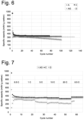
- Figures 7 and 8 show that for Grade C (rhombuses in Figure 7 ) and Grade D (squares in Figure 7 ) the specific capacity decreased only marginally (from 100% to 90%) at 10 C and was still only marginally reduced (from 100% to 87%) even up to 20 C.
- C-rate was reduced from 20 C to 0.5 C, it was still possible to recover 95-97% of the initial capacity.
- AG crosses in Figure 7
- the capacity was significantly reduced (from 100% to 71%) at 20 C.
- C-rate was reduced from 20 C to 0.5 C, it was not possible to recover the initial capacity of AG (from 100% to 83%).
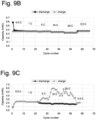
- FIGS. 9A , 9B, and 9C show the Coulombic efficiency for Grade C, Grade D and AG, respectively. Discharge corresponds to lithiation process and charge corresponds to the de-lithiation process. In an half-cell, Coulombic efficiency % is calculated as follows: (charge/discharge)*100. It can be seen that Coulombic efficiency is around 100% for Grade C and Grade D in the whole cycles 0.5 C to 20 C and back to 0.5 C, while it drops to around 60% for AG at 10 - 20 C.
Landscapes
- Chemical & Material Sciences (AREA)
- Engineering & Computer Science (AREA)
- Chemical Kinetics & Catalysis (AREA)
- Electrochemistry (AREA)
- General Chemical & Material Sciences (AREA)
- Materials Engineering (AREA)
- Manufacturing & Machinery (AREA)
- Inorganic Chemistry (AREA)
- Battery Electrode And Active Subsutance (AREA)
- Secondary Cells (AREA)
- Carbon And Carbon Compounds (AREA)
Claims (14)
- Verwendung von porösen, chemisch miteinander verbundenen, Kohlenstoff-Nanofasern umfassenden Kohlenstoffnetzwerken als elektrochemisch aktives Material in der Anode von wiederaufladbaren Lithium- oder Natriumbatterien,wobei die Kohlenstoff-Nanofasern in den Kohlenstoffnetzwerken kovalent gebunden sind,wobei die porösen Kohlenstoffnetzwerke ein intrapartikuläres poröses Netzwerk bilden, in dem die Kohlenstoff-Nanofasern durch chemische Bindungen über Verbindungsstellen mit anderen Kohlenstoff-Nanofasern in dem Netzwerk untereinander verbunden sind, wobei die Poren in dem Netzwerk eine intrapartikuläre Porendurchmessergröße von 5-150 nm unter Verwendung der Quecksilberintrusionsporosimetrie gemäß ASTM D4404-10 aufweisen und die Kohlenstoff-Nanofasern ein durchschnittliches Verhältnis von Faserlänge zu -dicke von mindestens 2 aufweisen, vorzugsweise mit einem d-Abstand im Bereich von 0,340 bis 0,5 nm.
- Verwendung nach Anspruch 1, wobei die Kohlenstoff-Nanofasern umfassenden Kohlenstoffnetzwerke 10 - 100 Gew.-%, vorzugsweise mehr als 10 und weniger als 100 Gew.-% der Gesamtmasse der Anode ausmachen.
- Verwendung nach Anspruch 1 oder 2, wobei das Kohlenstoffnetzwerk kristalline Kohlenstoff-Nanofasern umfasst.
- Verwendung nach einem der voranstehenden Ansprüche, wobei die durchschnittliche Faserlänge der Kohlenstoffnanofasern 30 - 10.000 nm beträgt.
- Verwendung nach einem der voranstehenden Ansprüche, wobei die Lithium- oder Natriumbatterien in Smartphones, Laptops, Digitalkameras und Camcordern, medizinischen und Kommunikationssystemen, als unterbrechungsfreie Stromversorgung (USV), als Energiespeicher für Kraftwerke und Elektro- und/oder Hybridfahrzeuge angewendet werden oder umfasst sind.
- Lithium- oder Natriumbatterieanode, umfassend poröse, chemisch miteinander verbundene, Kohlenstoff-Nanofasern umfassende Kohlenstoffnetzwerke als elektrochemisch aktives Material,wobei die Kohlenstoff-Nanofasern in den Kohlenstoffnetzwerken kovalent gebunden sind,wobei die porösen Kohlenstoffnetzwerke ein intrapartikuläres poröses Netzwerk bilden, in dem die Kohlenstoff-Nanofasern durch chemische Bindungen über Verbindungsstellen mit anderen Kohlenstoff-Nanofasern in dem Netzwerk untereinander verbunden sind, wobei die Poren in dem Netzwerk eine intrapartikuläre Porendurchmessergröße von 5-150 nm unter Verwendung der Quecksilberintrusionsporosimetrie gemäß ASTM D4404-10 aufweisen und die Kohlenstoff-Nanofasern ein durchschnittliches Verhältnis von Faserlänge zu -dicke von mindestens 2 aufweisen, vorzugsweise mit einem d-Abstand im Bereich von 0,340 bis 0,5 nm.
- Lithium- oder Natriumbatterieanode, umfassend poröse, chemisch miteinander verbundene, Kohlenstoff-Nanofasern umfassende Kohlenstoffnetzwerke, die 10 - 100 Gew.-%, vorzugsweise mehr als 10 und weniger als 100 Gew.-% der Gesamtmasse der Anode ausmachen,wobei die Kohlenstoff-Nanofasern in den Kohlenstoffnetzwerken kovalent gebunden sind,wobei die porösen Kohlenstoffnetzwerke ein intrapartikuläres poröses Netzwerk bilden, in dem die Kohlenstoff-Nanofasern durch chemische Bindungen über Verbindungsstellen mit anderen Kohlenstoff-Nanofasern in dem Netzwerk untereinander verbunden sind, wobei die Poren in dem Netzwerk eine intrapartikuläre Porendurchmessergröße von 5-150 nm unter Verwendung der Quecksilberintrusionsporosimetrie gemäß ASTM D4404-10 aufweisen und die Kohlenstoff-Nanofasern ein durchschnittliches Verhältnis von Faserlänge zu -dicke von mindestens 2 aufweisen, vorzugsweise mit einem d-Abstand im Bereich von 0,340 bis 0,5 nm.
- Batterieanode nach Anspruch 7, wobei die Batterie eine Lithiumbatterie ist, wobei die Anode 0,1 - 90 Gew.-% eines zusätzlichen aktiven Materials enthält, wobei das zusätzliche aktive Material Graphit, Silizium, eine Verbindung auf Siliziumbasis oder eine Kombination davon ist.
- Batterieanode nach Anspruch 8, wobei das zusätzliche aktive Material Silizium, eine Verbindung auf Siliziumbasis oder eine Kombination davon ist, wobei Silizium, die Verbindung auf Siliziumbasis oder eine Kombination davon mit den Kohlenstoff-Nanofasern umfassenden Kohlenstoffnetzwerken in der Anode gemischt sind oder die Kohlenstoff-Nanofasern umfassenden Kohlenstoffnetzwerke mit Silizium, der Verbindung auf Siliziumbasis oder einer Kombination davon beschichtet sind.
- Wiederaufladbare Lithium- oder Natriumbatterie, umfassend die Anode nach einem der Ansprüche 6-9.
- Verwendung nach einem der Ansprüche 1 - 5, Lithium- oder Natriumbatterieanode nach einem der Ansprüche 6-9 oder Lithium- oder Natriumbatterie nach Anspruch 10, wobei die Kohlenstoffnetzwerke durch ein Verfahren zur Herstellung kristalliner Kohlenstoffnetzwerke in einem Reaktor 3, der eine Reaktionszone 3b und eine Terminationszone 3c enthält, durch Injizieren einer Mikroemulsion vom Wasser-in-Öl, Öl-in-Wasser- oder bikontinuierlichen Typ c, umfassend Metallkatalysator-Nanopartikel, in die Reaktionszone 3b, die eine Temperatur von über 600 °C, vorzugsweise über 700 °C, bevorzugter über 900 °C, noch bevorzugter über 1000 °C, noch bevorzugter über 1100 °C, vorzugsweise bis zu 3000 °C, bevorzugter bis zu 2500 °C, am meisten bevorzugt bis zu 2000 °C aufweist, um kristalline Kohlenstoffnetzwerke e herzustellen, Übertragen dieser Netzwerke e in die Terminationszone 3c und Abschrecken oder Stoppen der Bildung kristalliner Kohlenstoffnetzwerke in der Terminationszone durch Einsprühen von Wasser d erhältlich sind.
- Batteriebetriebene Vorrichtung, umfassend die Lithium- oder Natriumbatterieanode nach einem der Ansprüche 6 - 9 oder die Lithium- oder Natriumbatterie nach Anspruch 10.
- Vorrichtung nach Anspruch 12, die ein Smartphone, ein Laptop, eine Energiespeichervorrichtung für Kraftwerke oder ein Elektro- oder Hybridfahrzeug ist.
- Lithium- oder Natriumbatterieanode, umfassend poröse, chemisch miteinander verbundene Kohlenstoff-Nanofasern, die Kohlenstoffnetzwerke als elektrochemisch aktives Material umfassen, das 10 - 100 Gew.-%, vorzugsweise mehr als 10 und weniger als 100 Gew.-% der Gesamtmasse der Anode ausmacht.
Priority Applications (2)
| Application Number | Priority Date | Filing Date | Title |
|---|---|---|---|
| RS20250921A RS67213B1 (sr) | 2021-10-26 | 2022-10-25 | Novi anodni materijal u litijumskim i natrijumskim baterijama |
| EP25184758.8A EP4597631A3 (de) | 2021-10-26 | 2022-10-25 | Neues anodenmaterial in lithium- und natriumbatterien |
Applications Claiming Priority (2)
| Application Number | Priority Date | Filing Date | Title |
|---|---|---|---|
| EP21204839 | 2021-10-26 | ||
| PCT/EP2022/079750 WO2023072918A1 (en) | 2021-10-26 | 2022-10-25 | New anode material in lithium and sodium batteries |
Related Child Applications (1)
| Application Number | Title | Priority Date | Filing Date |
|---|---|---|---|
| EP25184758.8A Division EP4597631A3 (de) | 2021-10-26 | 2022-10-25 | Neues anodenmaterial in lithium- und natriumbatterien |
Publications (3)
| Publication Number | Publication Date |
|---|---|
| EP4423822A1 EP4423822A1 (de) | 2024-09-04 |
| EP4423822B1 true EP4423822B1 (de) | 2025-06-25 |
| EP4423822C0 EP4423822C0 (de) | 2025-06-25 |
Family
ID=78413710
Family Applications (2)
| Application Number | Title | Priority Date | Filing Date |
|---|---|---|---|
| EP25184758.8A Pending EP4597631A3 (de) | 2021-10-26 | 2022-10-25 | Neues anodenmaterial in lithium- und natriumbatterien |
| EP22812472.3A Active EP4423822B1 (de) | 2021-10-26 | 2022-10-25 | Neues anodenmaterial in lithium- und natriumbatterien |
Family Applications Before (1)
| Application Number | Title | Priority Date | Filing Date |
|---|---|---|---|
| EP25184758.8A Pending EP4597631A3 (de) | 2021-10-26 | 2022-10-25 | Neues anodenmaterial in lithium- und natriumbatterien |
Country Status (14)
| Country | Link |
|---|---|
| US (1) | US20240421308A1 (de) |
| EP (2) | EP4597631A3 (de) |
| JP (1) | JP2024540214A (de) |
| KR (1) | KR20240112845A (de) |
| CN (1) | CN118369785A (de) |
| AU (1) | AU2022374703A1 (de) |
| CA (1) | CA3237973A1 (de) |
| ES (1) | ES3041815T3 (de) |
| HU (1) | HUE072994T2 (de) |
| MX (1) | MX2024005088A (de) |
| PL (1) | PL4423822T3 (de) |
| RS (1) | RS67213B1 (de) |
| TW (1) | TW202338159A (de) |
| WO (1) | WO2023072918A1 (de) |
Families Citing this family (1)
| Publication number | Priority date | Publication date | Assignee | Title |
|---|---|---|---|---|
| CN118983502A (zh) * | 2024-07-31 | 2024-11-19 | 江苏天合储能有限公司 | 锂钠复合双离子电池及电池包 |
Family Cites Families (3)
| Publication number | Priority date | Publication date | Assignee | Title |
|---|---|---|---|---|
| AU6535998A (en) | 1997-02-26 | 1998-09-18 | Columbian Chemicals Company | Use of thermal carbon black as anode material for lithium-ion batteries |
| KR101162588B1 (ko) | 2010-05-14 | 2012-07-04 | 삼화콘덴서공업주식회사 | 음극활물질 및 그 제조방법과 그 음극활물질을 포함하는 2차 전지 및 슈퍼 커패시터 |
| KR102907620B1 (ko) | 2019-12-16 | 2026-01-05 | 현대자동차주식회사 | 리튬 이차전지용 양극재 및 이의 제조방법 |
-
2022
- 2022-10-25 CA CA3237973A patent/CA3237973A1/en active Pending
- 2022-10-25 CN CN202280079427.8A patent/CN118369785A/zh active Pending
- 2022-10-25 HU HUE22812472A patent/HUE072994T2/hu unknown
- 2022-10-25 MX MX2024005088A patent/MX2024005088A/es unknown
- 2022-10-25 PL PL22812472.3T patent/PL4423822T3/pl unknown
- 2022-10-25 ES ES22812472T patent/ES3041815T3/es active Active
- 2022-10-25 KR KR1020247017055A patent/KR20240112845A/ko active Pending
- 2022-10-25 RS RS20250921A patent/RS67213B1/sr unknown
- 2022-10-25 US US18/704,065 patent/US20240421308A1/en active Pending
- 2022-10-25 JP JP2024525833A patent/JP2024540214A/ja active Pending
- 2022-10-25 WO PCT/EP2022/079750 patent/WO2023072918A1/en not_active Ceased
- 2022-10-25 AU AU2022374703A patent/AU2022374703A1/en active Pending
- 2022-10-25 EP EP25184758.8A patent/EP4597631A3/de active Pending
- 2022-10-25 EP EP22812472.3A patent/EP4423822B1/de active Active
- 2022-10-26 TW TW111140662A patent/TW202338159A/zh unknown
Also Published As
| Publication number | Publication date |
|---|---|
| EP4597631A2 (de) | 2025-08-06 |
| EP4423822A1 (de) | 2024-09-04 |
| ES3041815T3 (en) | 2025-11-14 |
| HUE072994T2 (hu) | 2025-12-28 |
| KR20240112845A (ko) | 2024-07-19 |
| AU2022374703A1 (en) | 2024-05-23 |
| EP4423822C0 (de) | 2025-06-25 |
| JP2024540214A (ja) | 2024-10-31 |
| CN118369785A (zh) | 2024-07-19 |
| CA3237973A1 (en) | 2023-05-04 |
| RS67213B1 (sr) | 2025-10-31 |
| WO2023072918A1 (en) | 2023-05-04 |
| US20240421308A1 (en) | 2024-12-19 |
| EP4597631A3 (de) | 2025-10-29 |
| TW202338159A (zh) | 2023-10-01 |
| PL4423822T3 (pl) | 2025-12-08 |
| MX2024005088A (es) | 2024-07-22 |
Similar Documents
| Publication | Publication Date | Title |
|---|---|---|
| TWI627783B (zh) | 鋰離子二次電池用電極材料、此電極材料的製造方法及鋰離子二次電池 | |
| US9923206B2 (en) | Encapsulated phthalocyanine particles, high-capacity cathode containing these particles, and rechargeable lithium cell containing such a cathode | |
| EP2485304A1 (de) | Negativelektroden-aktivmaterial, verfahren zur herstellung des negativelektroden-aktivmaterials und lithiumionen-sekundärbatterie mit dem negativelektroden-aktivmaterial | |
| JP6621663B2 (ja) | 導電性カーボンの製造方法、このカーボンを含む電極材料の製造方法、この電極材料を用いた電極の製造方法及びこの電極を備えた蓄電デバイスの製造方法 | |
| KR102400346B1 (ko) | 도전성 카본, 이 도전성 카본을 포함하는 전극 재료, 및 이 전극 재료를 사용한 전극 | |
| TW201415697A (zh) | 鋰離子二次電池用電極材料、其製造方法及鋰離子二次電池 | |
| CN105765774A (zh) | 导电性碳、包含该碳的电极材料、使用该电极材料的电极和具备该电极的蓄电器件 | |
| JP6436472B2 (ja) | 導電性カーボンの製造方法、導電性カーボンを含む電極材料の製造方法、及び、電極材料を用いた電極の製造方法 | |
| EP4423822B1 (de) | Neues anodenmaterial in lithium- und natriumbatterien | |
| WO2020255489A1 (ja) | 負極材、負極、電池セル | |
| US20250006941A1 (en) | New conductive additive in lithium and sodium batteries | |
| KR102394159B1 (ko) | 전극, 이 전극의 제조 방법, 이 전극을 구비한 축전 디바이스, 및 축전 디바이스 전극용 도전성 카본 혼합물 | |
| WO2024206397A2 (en) | Energy storage devices | |
| CN115867998A (zh) | 导电性碳及其制造方法、包含该导电性碳的导电性碳混合物的制造方法、以及使用了该导电性碳或导电性碳混合物的电极的制造方法 |
Legal Events
| Date | Code | Title | Description |
|---|---|---|---|
| STAA | Information on the status of an ep patent application or granted ep patent |
Free format text: STATUS: UNKNOWN |
|
| STAA | Information on the status of an ep patent application or granted ep patent |
Free format text: STATUS: THE INTERNATIONAL PUBLICATION HAS BEEN MADE |
|
| PUAI | Public reference made under article 153(3) epc to a published international application that has entered the european phase |
Free format text: ORIGINAL CODE: 0009012 |
|
| STAA | Information on the status of an ep patent application or granted ep patent |
Free format text: STATUS: REQUEST FOR EXAMINATION WAS MADE |
|
| 17P | Request for examination filed |
Effective date: 20240517 |
|
| AK | Designated contracting states |
Kind code of ref document: A1 Designated state(s): AL AT BE BG CH CY CZ DE DK EE ES FI FR GB GR HR HU IE IS IT LI LT LU LV MC ME MK MT NL NO PL PT RO RS SE SI SK SM TR |
|
| DAV | Request for validation of the european patent (deleted) | ||
| DAX | Request for extension of the european patent (deleted) | ||
| GRAP | Despatch of communication of intention to grant a patent |
Free format text: ORIGINAL CODE: EPIDOSNIGR1 |
|
| STAA | Information on the status of an ep patent application or granted ep patent |
Free format text: STATUS: GRANT OF PATENT IS INTENDED |
|
| INTG | Intention to grant announced |
Effective date: 20250218 |
|
| GRAS | Grant fee paid |
Free format text: ORIGINAL CODE: EPIDOSNIGR3 |
|
| GRAA | (expected) grant |
Free format text: ORIGINAL CODE: 0009210 |
|
| STAA | Information on the status of an ep patent application or granted ep patent |
Free format text: STATUS: THE PATENT HAS BEEN GRANTED |
|
| AK | Designated contracting states |
Kind code of ref document: B1 Designated state(s): AL AT BE BG CH CY CZ DE DK EE ES FI FR GB GR HR HU IE IS IT LI LT LU LV MC ME MK MT NL NO PL PT RO RS SE SI SK SM TR |
|
| REG | Reference to a national code |
Ref country code: GB Ref legal event code: FG4D |
|
| REG | Reference to a national code |
Ref country code: CH Ref legal event code: EP |
|
| REG | Reference to a national code |
Ref country code: DE Ref legal event code: R096 Ref document number: 602022016598 Country of ref document: DE |
|
| REG | Reference to a national code |
Ref country code: CH Ref legal event code: EP |
|
| REG | Reference to a national code |
Ref country code: IE Ref legal event code: FG4D |
|
| U01 | Request for unitary effect filed |
Effective date: 20250722 |
|
| U07 | Unitary effect registered |
Designated state(s): AT BE BG DE DK EE FI FR IT LT LU LV MT NL PT RO SE SI Effective date: 20250728 |
|
| PG25 | Lapsed in a contracting state [announced via postgrant information from national office to epo] |
Ref country code: HR Free format text: LAPSE BECAUSE OF FAILURE TO SUBMIT A TRANSLATION OF THE DESCRIPTION OR TO PAY THE FEE WITHIN THE PRESCRIBED TIME-LIMIT Effective date: 20250625 |
|
| REG | Reference to a national code |
Ref country code: GR Ref legal event code: EP Ref document number: 20250401912 Country of ref document: GR Effective date: 20251009 |
|
| REG | Reference to a national code |
Ref country code: ES Ref legal event code: FG2A Ref document number: 3041815 Country of ref document: ES Kind code of ref document: T3 Effective date: 20251114 |
|
| U20 | Renewal fee for the european patent with unitary effect paid |
Year of fee payment: 4 Effective date: 20251029 |
|
| PGFP | Annual fee paid to national office [announced via postgrant information from national office to epo] |
Ref country code: HU Payment date: 20251103 Year of fee payment: 4 |
|
| REG | Reference to a national code |
Ref country code: HU Ref legal event code: AG4A Ref document number: E072994 Country of ref document: HU |
|
| PG25 | Lapsed in a contracting state [announced via postgrant information from national office to epo] |
Ref country code: IS Free format text: LAPSE BECAUSE OF FAILURE TO SUBMIT A TRANSLATION OF THE DESCRIPTION OR TO PAY THE FEE WITHIN THE PRESCRIBED TIME-LIMIT Effective date: 20251025 |
|
| PGFP | Annual fee paid to national office [announced via postgrant information from national office to epo] |
Ref country code: NO Payment date: 20251029 Year of fee payment: 4 |
|
| PG25 | Lapsed in a contracting state [announced via postgrant information from national office to epo] |
Ref country code: SM Free format text: LAPSE BECAUSE OF FAILURE TO SUBMIT A TRANSLATION OF THE DESCRIPTION OR TO PAY THE FEE WITHIN THE PRESCRIBED TIME-LIMIT Effective date: 20250625 |
|
| PGFP | Annual fee paid to national office [announced via postgrant information from national office to epo] |
Ref country code: TR Payment date: 20251022 Year of fee payment: 4 Ref country code: GR Payment date: 20251027 Year of fee payment: 4 |
|
| PGFP | Annual fee paid to national office [announced via postgrant information from national office to epo] |
Ref country code: CZ Payment date: 20251022 Year of fee payment: 4 |
|
| PGFP | Annual fee paid to national office [announced via postgrant information from national office to epo] |
Ref country code: PL Payment date: 20251021 Year of fee payment: 4 |
|
| PG25 | Lapsed in a contracting state [announced via postgrant information from national office to epo] |
Ref country code: SK Free format text: LAPSE BECAUSE OF FAILURE TO SUBMIT A TRANSLATION OF THE DESCRIPTION OR TO PAY THE FEE WITHIN THE PRESCRIBED TIME-LIMIT Effective date: 20250625 |
|
| PGFP | Annual fee paid to national office [announced via postgrant information from national office to epo] |
Ref country code: RS Payment date: 20251022 Year of fee payment: 4 |
|
| PGFP | Annual fee paid to national office [announced via postgrant information from national office to epo] |
Ref country code: ES Payment date: 20251118 Year of fee payment: 4 |