EP4421373B1 - Trägeranordnung, vorzugsweise für ein belüftungssystem - Google Patents
Trägeranordnung, vorzugsweise für ein belüftungssystem Download PDFInfo
- Publication number
- EP4421373B1 EP4421373B1 EP24158524.9A EP24158524A EP4421373B1 EP 4421373 B1 EP4421373 B1 EP 4421373B1 EP 24158524 A EP24158524 A EP 24158524A EP 4421373 B1 EP4421373 B1 EP 4421373B1
- Authority
- EP
- European Patent Office
- Prior art keywords
- joint
- arm
- arm section
- support arrangement
- construction
- Prior art date
- Legal status (The legal status is an assumption and is not a legal conclusion. Google has not performed a legal analysis and makes no representation as to the accuracy of the status listed.)
- Active
Links
Images


Classifications
-
- F—MECHANICAL ENGINEERING; LIGHTING; HEATING; WEAPONS; BLASTING
- F16—ENGINEERING ELEMENTS AND UNITS; GENERAL MEASURES FOR PRODUCING AND MAINTAINING EFFECTIVE FUNCTIONING OF MACHINES OR INSTALLATIONS; THERMAL INSULATION IN GENERAL
- F16M—FRAMES, CASINGS OR BEDS OF ENGINES, MACHINES OR APPARATUS, NOT SPECIFIC TO ENGINES, MACHINES OR APPARATUS PROVIDED FOR ELSEWHERE; STANDS; SUPPORTS
- F16M13/00—Other supports for positioning apparatus or articles; Means for steadying hand-held apparatus or articles
- F16M13/02—Other supports for positioning apparatus or articles; Means for steadying hand-held apparatus or articles for supporting on, or attaching to, an object, e.g. tree, gate, window-frame, cycle
-
- B—PERFORMING OPERATIONS; TRANSPORTING
- B08—CLEANING
- B08B—CLEANING IN GENERAL; PREVENTION OF FOULING IN GENERAL
- B08B15/00—Preventing escape of dirt or fumes from the area where they are produced; Collecting or removing dirt or fumes from that area
- B08B15/04—Preventing escape of dirt or fumes from the area where they are produced; Collecting or removing dirt or fumes from that area from a small area, e.g. a tool
-
- F—MECHANICAL ENGINEERING; LIGHTING; HEATING; WEAPONS; BLASTING
- F16—ENGINEERING ELEMENTS AND UNITS; GENERAL MEASURES FOR PRODUCING AND MAINTAINING EFFECTIVE FUNCTIONING OF MACHINES OR INSTALLATIONS; THERMAL INSULATION IN GENERAL
- F16L—PIPES; JOINTS OR FITTINGS FOR PIPES; SUPPORTS FOR PIPES, CABLES OR PROTECTIVE TUBING; MEANS FOR THERMAL INSULATION IN GENERAL
- F16L3/00—Supports for pipes, cables or protective tubing, e.g. hangers, holders, clamps, cleats, clips, brackets
- F16L3/01—Supports for pipes, cables or protective tubing, e.g. hangers, holders, clamps, cleats, clips, brackets for supporting or guiding the pipes, cables or protective tubing, between relatively movable points, e.g. movable channels
- F16L3/015—Supports for pipes, cables or protective tubing, e.g. hangers, holders, clamps, cleats, clips, brackets for supporting or guiding the pipes, cables or protective tubing, between relatively movable points, e.g. movable channels using articulated- or supple-guiding elements
-
- F—MECHANICAL ENGINEERING; LIGHTING; HEATING; WEAPONS; BLASTING
- F16—ENGINEERING ELEMENTS AND UNITS; GENERAL MEASURES FOR PRODUCING AND MAINTAINING EFFECTIVE FUNCTIONING OF MACHINES OR INSTALLATIONS; THERMAL INSULATION IN GENERAL
- F16M—FRAMES, CASINGS OR BEDS OF ENGINES, MACHINES OR APPARATUS, NOT SPECIFIC TO ENGINES, MACHINES OR APPARATUS PROVIDED FOR ELSEWHERE; STANDS; SUPPORTS
- F16M11/00—Stands or trestles as supports for apparatus or articles placed thereon ; Stands for scientific apparatus such as gravitational force meters
- F16M11/02—Heads
- F16M11/04—Means for attachment of apparatus; Means allowing adjustment of the apparatus relatively to the stand
- F16M11/06—Means for attachment of apparatus; Means allowing adjustment of the apparatus relatively to the stand allowing pivoting
- F16M11/10—Means for attachment of apparatus; Means allowing adjustment of the apparatus relatively to the stand allowing pivoting around a horizontal axis
-
- F—MECHANICAL ENGINEERING; LIGHTING; HEATING; WEAPONS; BLASTING
- F16—ENGINEERING ELEMENTS AND UNITS; GENERAL MEASURES FOR PRODUCING AND MAINTAINING EFFECTIVE FUNCTIONING OF MACHINES OR INSTALLATIONS; THERMAL INSULATION IN GENERAL
- F16M—FRAMES, CASINGS OR BEDS OF ENGINES, MACHINES OR APPARATUS, NOT SPECIFIC TO ENGINES, MACHINES OR APPARATUS PROVIDED FOR ELSEWHERE; STANDS; SUPPORTS
- F16M11/00—Stands or trestles as supports for apparatus or articles placed thereon ; Stands for scientific apparatus such as gravitational force meters
- F16M11/20—Undercarriages with or without wheels
- F16M11/2007—Undercarriages with or without wheels comprising means allowing pivoting adjustment
- F16M11/2021—Undercarriages with or without wheels comprising means allowing pivoting adjustment around a horizontal axis
-
- F—MECHANICAL ENGINEERING; LIGHTING; HEATING; WEAPONS; BLASTING
- F24—HEATING; RANGES; VENTILATING
- F24F—AIR-CONDITIONING; AIR-HUMIDIFICATION; VENTILATION; USE OF AIR CURRENTS FOR SCREENING
- F24F13/00—Details common to, or for air-conditioning, air-humidification, ventilation or use of air currents for screening
- F24F13/02—Ducting arrangements
- F24F13/0254—Ducting arrangements characterised by their mounting means, e.g. supports
-
- F—MECHANICAL ENGINEERING; LIGHTING; HEATING; WEAPONS; BLASTING
- F16—ENGINEERING ELEMENTS AND UNITS; GENERAL MEASURES FOR PRODUCING AND MAINTAINING EFFECTIVE FUNCTIONING OF MACHINES OR INSTALLATIONS; THERMAL INSULATION IN GENERAL
- F16M—FRAMES, CASINGS OR BEDS OF ENGINES, MACHINES OR APPARATUS, NOT SPECIFIC TO ENGINES, MACHINES OR APPARATUS PROVIDED FOR ELSEWHERE; STANDS; SUPPORTS
- F16M2200/00—Details of stands or supports
- F16M2200/04—Balancing means
- F16M2200/044—Balancing means for balancing rotational movement of the undercarriage
Definitions
- the present invention relates to a support arrangement, preferably for a ventilation system comprising an air channel which is supported by the support arrangement, which support arrangement comprises:
- Such support arrangement may be used for a ventilation system.
- a flexible air channel will be held and supported by the support arrangement.
- the support arrangement will control the air channel, which is typically used for withdrawal of hazardous substances and gases.
- a negative pressure creates a suction acting on the air in the flexible channel and suction head which may be attached to the flexible channel to ensure that the ventilation system works in the manner desired. It is well-known that these ventilation systems are relatively heavy constructions and accordingly prior art systems are manufactured from aluminum in order to save weight.
- This prior art system solves the problem by providing a support arrangement made from aluminum and which has a balance arrangement between the first and second arm sections and comprising a tension construction having a first and a second end and attachment means for attaching each of the first and second end to the two arm sections.
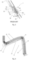
- Fig. 1 illustrates an arrangement 1 intended to be used in a ventilation arrangement in order to hold and control an air channel 2.
- the air channel 2 is intended for the extraction of air and at least one of undesired particles and gases from various places, normally working areas of various types.
- the air channel 2 is connected to a unit, not shown in the drawings, that creates negative pressure in the flexible channel 2, a force that withdraws air.
- the arrangement 1 comprises one single arm construction, which is arranged along the outer surface of the air channel 2A.
- the prior art arm construction is shown in Figure 1 and comprises two arm sections 3 and 4, two linkage arms, a first arm section 3 and a second arm section 4, arranged one after the other.
- the arm construction further comprises a first joint 5, a friction joint, that unites the first arm section with a fixture arrangement 6 that holds and sets the basic position of the arm construction and that makes different positioning, bending and stretching, of the arm construction possible.
- the arm construction further comprises a second joint 7, a friction joint, that unites the first arm section 3 with the second arm section 4 and that makes different positioning, bending and stretching, of the arm construction possible.
- Each arm section 3 and 4 comprises an aluminum profile 8 and 9 that is extended and should appropriately be manufactured by extrusion.
- Each arm section 3 and 4 is mainly constituted by the aluminum profiles 8 and 9 in the central part that gives the arm section its longitudinal extension.
- the arrangement 1 will be light in its construction, and this means that it is easy to displace it during transport, during assembly and during use, and thus also when displacing the arrangement 1 and an air channel 2 together, since the arrangement 1 comprises only a single arm construction with arm sections 3 and 4 that comprise an aluminum profile 8 and 9.
- the use of aluminum makes the construction lighter than arrangements with arm sections of steel.
- the parts made from aluminum can be made smaller while remaining stable.
- the arm construction is lighter, smaller and more attractive makes it possible to arrange the arm construction fully visible on the outer surface of the air channel 2A. This makes manufacture, transport and assembly easier, since components can be manufactured and delivered separately to be assembled on site. The use and the adaptation of the arm construction is also made easier, since an air channel 2 that is suitable for the purpose can be used. It becomes possible to use the same arm construction 1 in different contexts simply by exchanging the air channel 2.
- the air channel 2 is flexible, it can be bent, at least at those parts that are coincident in location with the joints 5 and 7.
- the air channel 2 may be constituted by or it may comprise a tube or more rigid parts.
- the aluminum profile 8 or 9 of each arm section is a hollow profile.
- Each arm section 3 and 4 comprises a side 11 and 12, respectively, an outer surface that faces the air channel 2 and which has an exterior that is formed to support the air channel 2 that lies exterior to the arm construction.
- the air channel 2 prefferably be principally circular, and one side 11, 12, of each arm section to have an exterior concave design that corresponds to the outer form of the channel in order to give maximum support to the air channel.
- An air intake arrangement in form of a hood 67 whose position can be adjusted is united with an arm arrangement 56 which is attached at the outermost arm section 4 which comprises a baffle construction 57.
- the hood 67 is united with the arm arrangement 56 through a construction having a second air channel 69 that also is fixed to the arm arrangement 56 and in the hood 67, and where the construction makes it possible to adjust the position, the angle, the tilt and the direction of the hood 67 relative to the arm arrangement 56.
- the arm arrangement 56 comprises also a part 56A, a handle, that can be gripped by one hand and that can transfer a force from a person to the arrangement 1 such that the position of the arrangement 1, the arm construction and the air channel 2 can be adjusted.
- Fig. 2 and 3 are partial views of the second joint 7 of the arrangement 1.
- Fig. 2 and 3 illustrate a balance arrangement 50 that is arranged between the second joint 7 and the first arm section 3 and comprising a fixture means 51, a fixture disk, arranged around the axis 36 of rotation of the joint fixed attached to the outer surface of the joint and comprising a part 52 that protrudes from the joint 7 and a tension construction 53, a gas spring that is attached at one end 53a in a manner that allows rotation relative to the protruding part 52, its outer free part, and that is attached at its second end to the first arm section 3 in a manner that allows rotation relative to the first arm section 3.
- the central line 52L of the protruding part has an angle a, which lies within the interval 75°- 105°, relative to a central line 4L of the arm section 4, the second arm section, that is fixed attached with the part of the joint 35, the second part of the second joint, to which the fixture means 51 is fixed attached.
- the interval of angles 80°-100° further ensures a better, more stable function of the balance arrangement 50.
- the fixture means 51 comprises a through hole through which the shaft 36 is to be placed and it has also a pre-determined form that is brought into interaction with a part outwardly directed from the joint 7 arranged around the shaft 36, with a form that corresponds to the form of the hole, such that the position of the fixture means 51 is determined relative to the joint 7.
- the hole and the outwardly directed part may have an interacting X-form such that the location of the fixture means, the fixture disk, can be changed by the release of the attachment means 51 from the outwardly directed part, rotation of the fixture means 51 relative to the outwardly directed part, and a new interaction of the fixture means 51 and the outwardly directed part is provided.
- the protruding part 52 of the balance arrangement 50 is important as the angle in the interval 80°-100° ensures a better, more stable function of the balance arrangement 50 and makes it easy to manoeuvre the ventilation system supported by the support arrangement.
- the two arm constructions are directly connected with the balance arrangement.
- directly connection in this application is meant that the first and second end of the balance arrangement are connected to the arm sections without being connected to the joint connecting the two arm sections.
- the two arm sections are connected directly to the first and second end of the tension construction.
- the joint may be a technical simple joint having a first and a second joint part being interconnected with a rotation pin or shaft.
- the first and second end of the tension construction is directly attached to the two arm sections.
- a first arm section will comprise a protruding part. This part is easy to attach to the first arm section.
- the attachment may be effected by screwing, welding, a gluing or other suitable means.
- a protruding part as an integral part of the first arm section.
- the second arm section will also comprise a fixture means which is a second fixture means which is intended for cooperation with the attachment means provided at the second end of the attachment construction.
- first and second fixture means in a position which allows the relative movement of the two sections through an angle in the interval between 25° and 180°. This angle is measured between a longitudinal axis for each of the two arm sections.
- the construction to provide the two arm sections in a position lying close to each other (illustrated in Fig. 6 ) to a position where the two arm sections are perpendicular to each other (illustrated in Fig. 5 ) to a position where the two arm sections are arranged in extension of each other (illustrated in Fig. 7 ) where the mutual angle would almost be 180°.
- the interval of the angle will ensure a stable function of the balance arrangement.
- the protruding part is provided in form of a plate-shaped member.
- This plate will have a first plate part being connected to a side face of the first arm section.
- the arm section normally will have a rectangular tubular form, and accordingly, it is easy to attach the first part of the plate to a side face of the first arm in such a way that the plate is arranged perpendicular to the axis of rotation for the joint.
- the second plate part will extend outwardly from the first arm section and in direction of the longitudinal axis of the first arm section and being arranged in the plane perpendicular to the axis of rotation.
- the protruding part is provided by the second plate part in a technical simple manner without interfering with the joint connecting the two arm sections.
- the support arrangement according to the invention is peculiar in that the second plate part is provided with an angle in an interval between 25 and 45° as measured between a longitudinal axis of the first arm section and a longitudinal axis of the second plate part.
- the second plate part With an angle having such size, it is possible that the second plate part will be provided in a position outside the joint and make it possible to provide the first fixture means in a position allowing the two arm sections to rotate through a mutual angle in the interval between 25° and 180°.
- the support arrangement according to the invention is peculiar in that the protruding part has an extension so the first fixture means are arranged in a position beyond the end of the first arm section and which position is arranged next to the joint region between the two arm sections where the first joint is arranged.
- the fixture means arranged in a position outside the joint region.
- joint region is meant the area between the two arm sections when they are arranged in extension of each other.
- the fixture means would be arranged in a position which is beyond the end of the first arm section.
- this position is also arranged close to the joint region which is the region being delimited of the extension of the side faces of the arm sections being connected with the joint.
- the extension of the protruding part is limited and will be a relatively compact construction.
- the support arrangement according to the invention is peculiar in that the protruding part has an extension so that the first fixture means are arranged in a position closer to the second arm section to which the first fixture means are not connected than to the first arm section as seen relative to the axis of rotation.
- the protruding part has such extension that the first fixture means arranged on the protruding part will be in a position closer to the second arm than to the first arm. This position is seen in relation to the axis of rotation.
- the first fixture means will be arranged in a position pass the axis of rotation when the two arm sections are arranged in direct extension of each other.
- the support arrangement according to the invention is peculiar in that the fixture means and the attachment means are provided as elements which allow a mutual rotation.
- the fixture means and the attachment means will be provided in such a way that the mutual rotation will be unhindered.
- the elements could both be rotatable, however, what is important is that there is a mutual possibility of rotation between the fixture means and the attachment means.
- each of the fixture means comprise a rotation pin and each of the attachment means comprise a bearing or vice versa.
- the fixture means may be provided in form of a rotation pin and the attachment means may be provided in form of a bearing.
- the construction could also be the other way around in such a way that the bearings are arranged on the arm sections and the rotation pin is a part of the tension construction.
- the support arrangement according to the invention is peculiar in that the fixture means are screwed onto a side of the first and second arm section respectively with screws, which preferably also are used to attach at least one of the joint parts of the first joint to the first arm section.
- the fixture means into the side of the first and second arm with screws. Also, other attachment means are possible to use.
- joint parts would be connected to the arm sections with screws screwed through the side walls of the arm sections and into a part of the joint extending into the hollow interior of the arm sections.
- At least the joint part of the first part may be attached with the screws which are also used to attach the plate in which the protruding parts are provided.
- the support arrangement according to the invention is peculiar in that the tension construction is a cylinder-piston unit.
- the tension construction will in an especially simple way be a cylinder-piston unit which is known from the prior art. Such unit will have a dampening function which could provide a stable mutual position of the two arms. Accordingly, the balance arrangement will be dimensioned according to the weight of the arm construction and the elements which are attached to the support construction.
- the support arrangement according to the invention is peculiar in that the shaft of the first joint comprises a screw which passes through the first joint part and the second joint part and is fixed by a bolt.
- the shaft for the first joint in different embodiments. It may be provided as a pin or other elements. However, it is an especially simple construction to provide a screw and to fix the screw with a bolt in a position maintaining the two joint parts in a mutual position allowing for the mutual rotation.
- Figs. 1-3 show the support arrangement of the type disclosed in WO2011/115558 . This arrangement has been explained above.
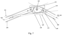
- Figs. 4-7 show the support arrangement according to the present invention.
- Fig. 4 illustrates a support arrangement 101 intended to hold and control an air channel 102.
- the support arrangement 101 is arranged along the outer surface of the air channel 102.
- the support arrangement comprises an arm construction consisting of two arm sections, namely a first arm section 103 and a second arm section 104.
- the two arm sections are connected through a first joint 105.
- the support arrangement is connected with a fixed support 106, e.g. mounted on a wall, through a second joint 107.
- first and second joint 105, 107 makes it possible to obtain different positioning, bending and stretching of the arm construction.
- Each arm section 103, 104 comprises a hollow rectangular aluminium profile 108 and 109.
- Figs. 5-7 illustrate a detailed view of the two arm sections 103, 104 being connected with the first joint 105.
- the first joint 105 comprises a first joint part 110 being connected with the first arm section 103 and a second joint part 111 being connected with the second arm part 104.
- the joint parts 110, 111 are connected through a shaft 112 passing through the first and second joint parts and making it possible to rotate around an axis of rotation 113 (being perpendicular to the plane of the paper).
- the system also comprises a balance arrangement 114 consisting of a cylinder-piston unit forming a tension construction 115.
- the tension construction has a first end 116 and a second end 117.
- the balance arrangement 114 is arranged between the first arm section 103 and the second arm section 104.
- the tension construction is provided with a first attachment means 118 and second attachment means 119 at each end of the tension construction 115.
- the first attachment means 118 is intended to be connected with a first fixture means 120 provided on the first arm section 103.
- the first fixture means 120 is provided on a plate 122 connected with the first arm section 103.
- the plate 122 comprises a first plate part 123 and a second plate part 124.
- the first plate part 123 is attached to the first arm section 103 with screws 127.
- the first plate part 123 is screwed to the side face of the first arm section 103 with screws 130 which are also used for attaching the first joint 105 to the first arm section 103.
- the first fixture means 120 may be provided by a rotation pin (not visible) attached to the second plate part 124 at the protruding part 126.
- the first arm section 103 has a longitudinal axis 128.
- the second arm section 104 has a longitudinal axis 129.
- the first plate part 123 has a longitudinal axis 130 which corresponds to the longitudinal axis 128 of the first arm section 103.
- the second plate part 124 has a longitudinal axis 131.
- the angle 136 will be in an interval between 20° and 45°.
- the longitudinal axis 128 of the first arm section 103 and the longitudinal axis 129 of the second arm section 104 form a mutual angle 135.
- the angle 135 which indicates the possible mutual rotation of the two arm sections 103 and 104 will be in an interval between 25° and 180°.
- the second attachment means 119 are intended to be attached to a second fixture means 121.
- the second fixture means 121 may also be provided by a rotation pin (not visible).
- the second fixture means 121 are attached to the second arm section 104 through a plate 132 which is connected to the second arm section 104 with screws 133.
- the shaft 112 between the first and second joint parts 110 and 111 of the first j oint 105 is provided by a screw passing through the joint parts and being fixed by a bolt 134.
Landscapes
- Engineering & Computer Science (AREA)
- General Engineering & Computer Science (AREA)
- Mechanical Engineering (AREA)
- Chemical & Material Sciences (AREA)
- Combustion & Propulsion (AREA)
- Mutual Connection Of Rods And Tubes (AREA)
- Manipulator (AREA)
Claims (10)
- Trägeranordnung (101), vorzugsweise für ein Belüftungssystem, das einen Luftkanal (102) umfasst, der von der Trägeranordnung getragen ist, wobei die Trägeranordnung Folgendes umfasst:- eine Armkonstruktion, die zwei Armabschnitte, einen ersten Armabschnitt (103) und einen zweiten Armabschnitt (104), die in Verlängerung zueinander angeordnet sind, umfasst,- ein erstes Gelenk (105), das die zwei Armabschnitte (103, 104) verbindet, wobei das erste Gelenk (105) ein erstes Gelenkteil (110), das an dem ersten Armabschnitt (103) angebracht ist, und ein zweites Gelenkteil (111), das an dem zweiten Armabschnitt (104) angebracht ist, umfasst, wobei die Gelenkteile durch eine Welle (112), die durch das erste und zweiten Gelenkteil passiert, miteinander verbunden sind und wobei das erste und zweite Gelenkteil um eine durch die Welle (112) gebildete Drehachse (113) relativ zueinander gedreht werden können,- ein zweites Gelenk (107), das die Trägeranordnung (101) mit einem festen Träger (106) verbindet, wobei das zweite Gelenk (107) eine Grundposition der Trägeranordnung (101) hält und aufrechterhält, so dass eine unterschiedliche Positionierung der Trägeranordnung möglich ist,- eine Ausgleichsanordnung (114), die eine Spannkonstruktion (115) umfasst, die ein erstes (116) und ein zweites Ende (117) aufweist,
und wobei- jeder Armabschnitt (103, 104) ein Hohlprofil (108, 109) umfasst und wobei das erste und zweite Gelenkteil (110, 111) des ersten Gelenks (105) in den Hohlprofilen (108, 109) montiert sind,
dadurch gekennzeichnet,- dass die Ausgleichsanordnung (114) zwischen dem ersten (103) und zweiten Armabschnitt (104) angeordnet ist,
dass die Spannkonstruktion (115) ein erstes und ein zweites Anbringungsmittel (118, 119) zum Anbringen des ersten (116) und zweiten Endes (117) der Spannkonstruktion (115) direkt an den beiden Armabschnitten (103, 104) aufweist und- dass der erste Armabschnitt (103) einen herausragenden Teil (126) umfasst, der in einer Ebene senkrecht zu der Drehachse (113) angeordnet ist und wobei der herausragende Teil von dem ersten Armabschnitt (103) zu einer Position außerhalb eines Gelenkbereichs (125) zwischen den beiden Armabschnitten (103, 104) herausragt, wo das erste Gelenk (105) angeordnet ist,- dass ein erstes Befestigungsmittel (120) an dem herausragenden Teil (126) angeordnet ist, wobei das erste Befestigungsmittel (120) mit dem ersten Anbringungsmittel (118) an dem ersten Ende (116) der Spannkonstruktion (115) zusammenwirkt,- dass der zweite Armabschnitt (104) ein zweites Befestigungsmittel (121) umfasst, das mit dem zweiten Anbringungsmittel (119) an dem zweiten Ende (117) der Spannkonstruktion (115) zusammenwirkt, und- dass das erste und zweite Befestigungsmittel (120, 121) eine relative Drehung der Armabschnitte (103, 104) in einem Winkel (135) in einem Intervall zwischen 25° und 180°, gemessen zwischen einer Längsachse (128, 129) der beiden Armabschnitte (103, 104), ermöglichen. - Trägeranordnung nach Anspruch 1, dadurch gekennzeichnet, dass der herausragende Teil (126) von einer Platte (122) bereitgestellt ist, die einen ersten Plattenteil (123), der mit einer Seitenfläche des ersten Armabschnitts (103) verbunden ist, und einen zweiten Plattenteil (124) aufweist, der sich nach außen und in Richtung der Längsachse (128) des ersten Armabschnitts (103) in einer Ebene senkrecht zu der Drehachse (113) erstreckt, wobei der zweite Plattenteil (124) den herausragenden Teil (126) bereitstellt.
- Trägeranordnung nach Anspruch 2, dadurch gekennzeichnet, dass der zweite Plattenteil (124) mit einem Winkel (136) in einem Intervall zwischen 20° und 45°, gemessen zwischen einer Längsachse (128) des ersten Armabschnitts (103) und einer Längsachse (131) des zweiten Plattenteils (124), bereitgestellt ist.
- Trägeranordnung nach einem der vorhergehenden Ansprüche, dadurch gekennzeichnet, dass der herausragende Teil (126) eine Verlängerung aufweist, so dass das erste Befestigungsmittel (120) in einer Position jenseits des Endes des ersten Armabschnitts (103) angeordnet ist und wobei die Position neben dem Gelenkbereich (125) zwischen den beiden Armabschnitten angeordnet ist, wo das erste Gelenk (105) angeordnet ist.
- Trägeranordnung nach einem der vorhergehenden Ansprüche, dadurch gekennzeichnet, dass der herausragende Teil (126) eine Verlängerung aufweist, so dass das erste Befestigungsmittel (120) in einer Position angeordnet ist, die relativ zu der Drehachse (113) gesehen näher an dem zweiten Armabschnitt (104) ist, mit dem das erste Befestigungsmittel (120) nicht verbunden ist, als an dem ersten Armabschnitt (103).
- Trägeranordnung nach einem der vorhergehenden Ansprüche, dadurch gekennzeichnet, dass die Befestigungsmittel (120, 121) und die Anbringungsmittel (118, 119) als Elemente bereitgestellt sind, die eine gegenseitige Drehung ermöglichen.
- Trägeranordnung nach Anspruch 6, dadurch gekennzeichnet, dass jedes der Befestigungsmittel (120, 121) einen Drehstift umfasst und jedes der Anbringungsmittel (118, 119) ein Lager umfasst oder umgekehrt.
- Trägeranordnung nach einem der vorhergehenden Ansprüche, dadurch gekennzeichnet, dass die Befestigungsmittel (120, 121) jeweils mit Schrauben (127, 130), die vorzugsweise auch zum Anbringen mindestens eines der Gelenkteile (110, 111) des ersten Gelenks (105) an dem ersten Armabschnitt (103) verwendet sind, auf eine Seite des ersten und zweiten Armabschnitts (103, 104) geschraubt sind.
- Trägeranordnung nach einem der vorhergehenden Ansprüche, dadurch gekennzeichnet, dass die Spannkonstruktion (115) eine Zylinder-Kolben-Einheit ist.
- Trägeranordnung nach einem der vorhergehenden Ansprüche, dadurch gekennzeichnet, dass die Welle (112) des ersten Gelenks (105) eine Schraube umfasst, die durch das erste Gelenkteil (110) und das zweite Gelenkteil (111) passiert und durch einen Bolzen (134) befestigt ist.
Applications Claiming Priority (1)
| Application Number | Priority Date | Filing Date | Title |
|---|---|---|---|
| DKPA202370102A DK181494B1 (en) | 2023-02-24 | 2023-02-24 | A support arrangement preferably for a ventilation system |
Publications (3)
| Publication Number | Publication Date |
|---|---|
| EP4421373A1 EP4421373A1 (de) | 2024-08-28 |
| EP4421373B1 true EP4421373B1 (de) | 2025-06-18 |
| EP4421373C0 EP4421373C0 (de) | 2025-06-18 |
Family
ID=90014463
Family Applications (1)
| Application Number | Title | Priority Date | Filing Date |
|---|---|---|---|
| EP24158524.9A Active EP4421373B1 (de) | 2023-02-24 | 2024-02-20 | Trägeranordnung, vorzugsweise für ein belüftungssystem |
Country Status (2)
| Country | Link |
|---|---|
| EP (1) | EP4421373B1 (de) |
| DK (1) | DK181494B1 (de) |
Family Cites Families (7)
| Publication number | Priority date | Publication date | Assignee | Title |
|---|---|---|---|---|
| DE3225953A1 (de) * | 1982-07-10 | 1984-01-12 | Schmidt, Kranz & Co GmbH Zweigniederlassung Zorge, 3421 Zorge | Absaugarm zum absaugen von rauch und gasen |
| US5170975A (en) * | 1991-06-06 | 1992-12-15 | Alan Chadwick | Articulated arm with spring for counterbalancing |
| NZ260020A (en) * | 1993-04-22 | 1995-04-27 | Iowa Mold Tooling Co | Articulating boom, for a logging truck, with inner boom connected to outer boom by a pivoted short link and a synchronising mechanism |
| WO2008140361A1 (en) * | 2007-05-11 | 2008-11-20 | Fumex Ab | Mounting device, joint construction, ventilating arm, ventilating system |
| SE531913C2 (sv) * | 2008-01-18 | 2009-09-08 | Fumex Ab | Ventilationsarm,ventilationssystem,samt anordning innefattande i ett ventilationssystem |
| SE535576C2 (sv) * | 2010-03-18 | 2012-10-02 | Fumex Ab | Anordning och ventilationsanordning |
| CN107110423B (zh) * | 2014-11-16 | 2019-03-01 | 加勒特·W·布朗 | 拉伸平行四边形臂 |
-
2023
- 2023-02-24 DK DKPA202370102A patent/DK181494B1/en active IP Right Grant
-
2024
- 2024-02-20 EP EP24158524.9A patent/EP4421373B1/de active Active
Also Published As
| Publication number | Publication date |
|---|---|
| DK181494B1 (en) | 2024-03-08 |
| DK202370102A1 (en) | 2024-03-08 |
| EP4421373A1 (de) | 2024-08-28 |
| EP4421373C0 (de) | 2025-06-18 |
| DK202370102A9 (en) | 2024-03-21 |
Similar Documents
| Publication | Publication Date | Title |
|---|---|---|
| US6283428B1 (en) | Swing arm mount system | |
| CN101680264B (zh) | 连接器 | |
| RU2395380C2 (ru) | Параллельный кинематический механизм | |
| US9656309B2 (en) | Arrangement and ventilation arrangement | |
| CA2465464C (en) | Folding pinnacle bending device | |
| JP2010516533A (ja) | 航空機の胴体構造体を補強するおよび/または構成部品を固定するための装置、特にコネクションロッド | |
| EP4421373A1 (de) | Trägeranordnung, vorzugsweise für ein belüftungssystem | |
| CN103291163A (zh) | 具有带无限旋转调整的直端部扭矩杆的行李箱盖铰链平衡组件 | |
| US5832978A (en) | Joint arm for a joint arm awning | |
| CN108779818B (zh) | 盘式制动器 | |
| JP2005048948A (ja) | 二つの機械部材間のリンク | |
| WO2018045389A1 (en) | Precision aiming systems and methods | |
| JP5606794B2 (ja) | クレーンステー用摩擦ダンパー | |
| EP1612134B1 (de) | Vorderradgabel für Fahrräder | |
| US7828452B2 (en) | Vehicle mirror support assembly with cast brace | |
| JP3799536B2 (ja) | ポ―タブルスポットガン用吊り金具取付ベ―ス | |
| US8641067B2 (en) | Suspension unit | |
| JP4170976B2 (ja) | 屋根置台 | |
| EP2745022B1 (de) | Lagergehäuse und seine verwendung | |
| CN223000598U (zh) | 喷漆机器人及其机械臂 | |
| CN214785165U (zh) | 一种采光顶玻璃夹具 | |
| JP4034649B2 (ja) | プレート固定用エレメント | |
| KR101831244B1 (ko) | 허브 커넥터 | |
| FI120026B (fi) | Pyörän kiinnitys | |
| RU2588478C2 (ru) | Устройство и вентиляционное устройство |
Legal Events
| Date | Code | Title | Description |
|---|---|---|---|
| PUAI | Public reference made under article 153(3) epc to a published international application that has entered the european phase |
Free format text: ORIGINAL CODE: 0009012 |
|
| STAA | Information on the status of an ep patent application or granted ep patent |
Free format text: STATUS: THE APPLICATION HAS BEEN PUBLISHED |
|
| AK | Designated contracting states |
Kind code of ref document: A1 Designated state(s): AL AT BE BG CH CY CZ DE DK EE ES FI FR GB GR HR HU IE IS IT LI LT LU LV MC ME MK MT NL NO PL PT RO RS SE SI SK SM TR |
|
| STAA | Information on the status of an ep patent application or granted ep patent |
Free format text: STATUS: REQUEST FOR EXAMINATION WAS MADE |
|
| 17P | Request for examination filed |
Effective date: 20250205 |
|
| GRAP | Despatch of communication of intention to grant a patent |
Free format text: ORIGINAL CODE: EPIDOSNIGR1 |
|
| STAA | Information on the status of an ep patent application or granted ep patent |
Free format text: STATUS: GRANT OF PATENT IS INTENDED |
|
| GRAS | Grant fee paid |
Free format text: ORIGINAL CODE: EPIDOSNIGR3 |
|
| INTG | Intention to grant announced |
Effective date: 20250409 |
|
| GRAA | (expected) grant |
Free format text: ORIGINAL CODE: 0009210 |
|
| STAA | Information on the status of an ep patent application or granted ep patent |
Free format text: STATUS: THE PATENT HAS BEEN GRANTED |
|
| AK | Designated contracting states |
Kind code of ref document: B1 Designated state(s): AL AT BE BG CH CY CZ DE DK EE ES FI FR GB GR HR HU IE IS IT LI LT LU LV MC ME MK MT NL NO PL PT RO RS SE SI SK SM TR |
|
| REG | Reference to a national code |
Ref country code: GB Ref legal event code: FG4D |
|
| REG | Reference to a national code |
Ref country code: CH Ref legal event code: EP |
|
| REG | Reference to a national code |
Ref country code: DE Ref legal event code: R096 Ref document number: 602024000203 Country of ref document: DE |
|
| REG | Reference to a national code |
Ref country code: CH Ref legal event code: EP |
|
| REG | Reference to a national code |
Ref country code: IE Ref legal event code: FG4D |
|
| U01 | Request for unitary effect filed |
Effective date: 20250708 |
|
| U07 | Unitary effect registered |
Designated state(s): AT BE BG DE DK EE FI FR IT LT LU LV MT NL PT RO SE SI Effective date: 20250714 |
|
| PG25 | Lapsed in a contracting state [announced via postgrant information from national office to epo] |
Ref country code: NO Free format text: LAPSE BECAUSE OF FAILURE TO SUBMIT A TRANSLATION OF THE DESCRIPTION OR TO PAY THE FEE WITHIN THE PRESCRIBED TIME-LIMIT Effective date: 20250918 Ref country code: GR Free format text: LAPSE BECAUSE OF FAILURE TO SUBMIT A TRANSLATION OF THE DESCRIPTION OR TO PAY THE FEE WITHIN THE PRESCRIBED TIME-LIMIT Effective date: 20250919 |
|
| PG25 | Lapsed in a contracting state [announced via postgrant information from national office to epo] |
Ref country code: HR Free format text: LAPSE BECAUSE OF FAILURE TO SUBMIT A TRANSLATION OF THE DESCRIPTION OR TO PAY THE FEE WITHIN THE PRESCRIBED TIME-LIMIT Effective date: 20250618 |
|
| PG25 | Lapsed in a contracting state [announced via postgrant information from national office to epo] |
Ref country code: RS Free format text: LAPSE BECAUSE OF FAILURE TO SUBMIT A TRANSLATION OF THE DESCRIPTION OR TO PAY THE FEE WITHIN THE PRESCRIBED TIME-LIMIT Effective date: 20250918 |
|
| PG25 | Lapsed in a contracting state [announced via postgrant information from national office to epo] |
Ref country code: IS Free format text: LAPSE BECAUSE OF FAILURE TO SUBMIT A TRANSLATION OF THE DESCRIPTION OR TO PAY THE FEE WITHIN THE PRESCRIBED TIME-LIMIT Effective date: 20251018 |
|
| PG25 | Lapsed in a contracting state [announced via postgrant information from national office to epo] |
Ref country code: SM Free format text: LAPSE BECAUSE OF FAILURE TO SUBMIT A TRANSLATION OF THE DESCRIPTION OR TO PAY THE FEE WITHIN THE PRESCRIBED TIME-LIMIT Effective date: 20250618 |
|
| PG25 | Lapsed in a contracting state [announced via postgrant information from national office to epo] |
Ref country code: CZ Free format text: LAPSE BECAUSE OF FAILURE TO SUBMIT A TRANSLATION OF THE DESCRIPTION OR TO PAY THE FEE WITHIN THE PRESCRIBED TIME-LIMIT Effective date: 20250618 |
|
| PG25 | Lapsed in a contracting state [announced via postgrant information from national office to epo] |
Ref country code: PL Free format text: LAPSE BECAUSE OF FAILURE TO SUBMIT A TRANSLATION OF THE DESCRIPTION OR TO PAY THE FEE WITHIN THE PRESCRIBED TIME-LIMIT Effective date: 20250618 |
|
| PG25 | Lapsed in a contracting state [announced via postgrant information from national office to epo] |
Ref country code: SK Free format text: LAPSE BECAUSE OF FAILURE TO SUBMIT A TRANSLATION OF THE DESCRIPTION OR TO PAY THE FEE WITHIN THE PRESCRIBED TIME-LIMIT Effective date: 20250618 |
|
| PG25 | Lapsed in a contracting state [announced via postgrant information from national office to epo] |
Ref country code: ES Free format text: LAPSE BECAUSE OF FAILURE TO SUBMIT A TRANSLATION OF THE DESCRIPTION OR TO PAY THE FEE WITHIN THE PRESCRIBED TIME-LIMIT Effective date: 20250618 |
|
| U20 | Renewal fee for the european patent with unitary effect paid |
Year of fee payment: 3 Effective date: 20260227 |
|
| PLBE | No opposition filed within time limit |
Free format text: ORIGINAL CODE: 0009261 |
|
| STAA | Information on the status of an ep patent application or granted ep patent |
Free format text: STATUS: NO OPPOSITION FILED WITHIN TIME LIMIT |
|
| REG | Reference to a national code |
Ref country code: CH Ref legal event code: L10 Free format text: ST27 STATUS EVENT CODE: U-0-0-L10-L00 (AS PROVIDED BY THE NATIONAL OFFICE) Effective date: 20260430 |