EP4421233A1 - Tambour pour sèche-linge et sèche-linge doté du tambour - Google Patents
Tambour pour sèche-linge et sèche-linge doté du tambour Download PDFInfo
- Publication number
- EP4421233A1 EP4421233A1 EP24153690.3A EP24153690A EP4421233A1 EP 4421233 A1 EP4421233 A1 EP 4421233A1 EP 24153690 A EP24153690 A EP 24153690A EP 4421233 A1 EP4421233 A1 EP 4421233A1
- Authority
- EP
- European Patent Office
- Prior art keywords
- drum
- sub
- filter
- air
- outlet
- Prior art date
- Legal status (The legal status is an assumption and is not a legal conclusion. Google has not performed a legal analysis and makes no representation as to the accuracy of the status listed.)
- Pending
Links
- 238000001035 drying Methods 0.000 claims abstract description 77
- 238000004140 cleaning Methods 0.000 claims abstract description 50
- 238000001914 filtration Methods 0.000 claims abstract description 13
- 238000004891 communication Methods 0.000 claims description 31
- 230000003014 reinforcing effect Effects 0.000 claims description 20
- XLYOFNOQVPJJNP-UHFFFAOYSA-N water Substances O XLYOFNOQVPJJNP-UHFFFAOYSA-N 0.000 claims description 19
- 239000007921 spray Substances 0.000 claims description 8
- 238000011144 upstream manufacturing Methods 0.000 claims description 8
- 238000009833 condensation Methods 0.000 description 26
- 230000005494 condensation Effects 0.000 description 26
- 238000010438 heat treatment Methods 0.000 description 15
- 238000009825 accumulation Methods 0.000 description 6
- 238000010586 diagram Methods 0.000 description 4
- 230000000694 effects Effects 0.000 description 2
- 238000005516 engineering process Methods 0.000 description 2
- 230000002708 enhancing effect Effects 0.000 description 2
- 238000001746 injection moulding Methods 0.000 description 2
- 238000000034 method Methods 0.000 description 2
- 238000007789 sealing Methods 0.000 description 2
- 238000005406 washing Methods 0.000 description 2
- 241000894006 Bacteria Species 0.000 description 1
- 239000002826 coolant Substances 0.000 description 1
- 239000000428 dust Substances 0.000 description 1
- 230000007774 longterm Effects 0.000 description 1
- 239000002184 metal Substances 0.000 description 1
- 239000002245 particle Substances 0.000 description 1
- 239000000243 solution Substances 0.000 description 1
- 238000005507 spraying Methods 0.000 description 1
Images


Classifications
-
- D—TEXTILES; PAPER
- D06—TREATMENT OF TEXTILES OR THE LIKE; LAUNDERING; FLEXIBLE MATERIALS NOT OTHERWISE PROVIDED FOR
- D06F—LAUNDERING, DRYING, IRONING, PRESSING OR FOLDING TEXTILE ARTICLES
- D06F58/00—Domestic laundry dryers
- D06F58/20—General details of domestic laundry dryers
- D06F58/22—Lint collecting arrangements
-
- D—TEXTILES; PAPER
- D06—TREATMENT OF TEXTILES OR THE LIKE; LAUNDERING; FLEXIBLE MATERIALS NOT OTHERWISE PROVIDED FOR
- D06F—LAUNDERING, DRYING, IRONING, PRESSING OR FOLDING TEXTILE ARTICLES
- D06F58/00—Domestic laundry dryers
- D06F58/02—Domestic laundry dryers having dryer drums rotating about a horizontal axis
- D06F58/04—Details
-
- D—TEXTILES; PAPER
- D06—TREATMENT OF TEXTILES OR THE LIKE; LAUNDERING; FLEXIBLE MATERIALS NOT OTHERWISE PROVIDED FOR
- D06F—LAUNDERING, DRYING, IRONING, PRESSING OR FOLDING TEXTILE ARTICLES
- D06F25/00—Washing machines with receptacles, e.g. perforated, having a rotary movement, e.g. oscillatory movement, the receptacle serving both for washing and for centrifugally separating water from the laundry and having further drying means, e.g. using hot air
-
- D—TEXTILES; PAPER
- D06—TREATMENT OF TEXTILES OR THE LIKE; LAUNDERING; FLEXIBLE MATERIALS NOT OTHERWISE PROVIDED FOR
- D06F—LAUNDERING, DRYING, IRONING, PRESSING OR FOLDING TEXTILE ARTICLES
- D06F37/00—Details specific to washing machines covered by groups D06F21/00 - D06F25/00
- D06F37/26—Casings; Tubs
- D06F37/267—Tubs specially adapted for mounting thereto components or devices not provided for in preceding subgroups
Definitions
- the present invention relates to a drum for a dryer, further relates to a dryer having the drum, and in particular, relates to the field of flint treatment technologies.
- a dryer usually includes a machine having only a dryer function and a machine that integrates a clothes washing function and a clothes drying function.
- a drying principle of the dryer may be approximately summarized as follows: Under the action of a heating apparatus, dry air is heated by the heating apparatus to form dry hot air. The dry hot air then enters a drying drum to perform thermal exchange with wet clothes to take away moisture in the clothes, and relatively moist hot air is formed. The moist hot air subsequently undergoes condensation by a condensation apparatus. The moisture in the moist hot air is condensed into water, and then the water is discharged through a drain pipe. The air becomes relatively dry cold air after the condensation, and is guided into the heating apparatus again under the action of a fan.
- the air is heated to form dry hot air to enter a next circulation. This cycle is repeated, until a drying procedure ends.
- a temperature sensor and a thermostat are disposed in the dryer to detect an air temperature to determine an operating status of the machine.
- flint falling off from the clothes tends to follow an air flow to enter a downstream air channel from inside the drum and accumulate in the air channel. This affects the flowing of air and increases an air resistance. As a result, drying efficiency and drying performance are affected. Long-term accumulation of flint tends to breed bacteria, affecting the cleanness of the machine.
- a heat exchanger an evaporator or a condenser
- a surface of the heat exchanger is highly prone to flint accumulation, leading to a sharp drop in thermal exchange efficiency.
- a filter needs to be disposed to perform filtering, to reduce flint that enters the air channel, and the filter is cleaned when flint accumulates.
- an air outlet with a large area usually needs to be provided in the drum.
- an opening with a large area causes a drop in the stiffness of the drum, and especially if an opening is provided in a back portion of the drum, a reinforcing rib at the back portion of the drum is cut through, which severely affects the mechanical performance of the drum.
- An objective of this application is to provide a drum for a dryer and a dryer having the drum, which can provide a large air outlet and a large filter area on the drum for the dryer without affecting the mechanical performance of the drum, thereby reducing a filtering resistance, implementing a low cleaning frequency, and improving drying efficiency and drying performance.
- the "flint” in this application is small pieces of thread and fluff generated in a treatment process of clothes, dust, and other particles contained in air that passes through a filter.
- upstream and “downstream” in this application are both discussed relative to a drying air flow direction when a filter is mounted in a drying air channel.
- an aspect of this application provides a drum for a dryer, including an air outlet for passage of air out of the drum from inside the drum and a filter disposed at the air outlet.
- the air outlet is formed in a drum wall and includes a plurality of sub-outlets.
- the air outlet in the drum of this application is constructed by the plurality of sub-outlets, and the plurality of sub-outlets jointly form the air outlet, so that a large air outlet can be implemented while the mechanical performance such as strength and stiffness of the drum is ensured, to implement a large filter area.
- the large filter area can bring about a small air resistance and a low filter cleaning frequency, thereby improving drying efficiency and drying performance.
- An optional implementation includes that the plurality of sub-outlets are independent of each other, so that an impact on the mechanical performance of the drum can be effectively reduced.
- An optional implementation further includes that the filter includes a plurality of sub-filtering regions, and the plurality of sub-filtering regions correspond one to one to the plurality of sub-outlets.
- An optional implementation further includes that the filter is disposed in the drum, and an end surface of the filter on an upstream side of a drying air flow direction is flush with an inner circumferential surface of the drum wall in which the filter is mounted or is concave in the inner circumferential surface, to avoid forming interference with other members in the drum; or the filter is disposed outside the drum.
- An optional implementation further includes that the drum further includes a filter cleaning portion, the filter cleaning portion includes a water dispenser and a plurality of spouts provided in the water dispenser, and the water dispenser is in communication with a cleaning medium and sprays the cleaning medium through the plurality of spouts to separate flint from the filter.
- the filter cleaning portion is disposed, and the filter is cleaned regularly or as required by using the cleaning medium, so that smooth passage of drying air can be ensured, and after a drying procedure is run for a period of time, blockage of the filter is avoided, the drying performance or efficiency is kept from being reduced, and the drying procedure is not affected.
- the spouts are provided in a downstream side of a drying air flow direction relative to the filter and sprays the cleaning medium to a surface of the filter.
- the spouts have a plurality of regions, and each region corresponds to one sub-outlet, to spray the cleaning medium to a corresponding region of the filter.
- An optional implementation further includes that the drum further includes a connecting portion in communication with the air outlet, the connecting portion is disposed outside the drum and includes an inlet end, and the inlet end is in communication with each of the plurality of sub-outlets.
- the filter is disposed between the drum and the connecting portion or in the connecting portion or in the air outlet.
- the inlet end includes a plurality of sub-inlets, and the plurality of sub-inlets correspond one to one to and are respectively in communication with the plurality of sub-outlets.
- the connecting portion further includes a channel and an outlet end, and the channel is in communication with each of the plurality of sub-inlets and the outlet end.
- a plurality of reinforcing ribs are disposed on a side of a rear wall of the drum facing outside the drum in a radial direction and circumferential direction, the reinforcing ribs form a plurality of accommodating regions, and each of the plurality of sub-outlets is formed in the rear wall at a position corresponding to one of the plurality of accommodating regions, to effectively use spaces between the reinforcing ribs without affecting the effect of enhancing the strength of the drum by the reinforcing ribs.
- each of the plurality of sub-inlets is formed through surrounding by a circumferentially closed wall, and each of the plurality of sub-inlets is inserted into a reinforcing rib forming a corresponding accommodating region to be in communication with a corresponding sub-outlet. Furthermore, one sub-seal member is disposed between each sub-inlet and a corresponding sub-outlet, and a side seal is formed between each sub-inlet and a reinforcing rib forming a corresponding accommodating region or an end surface seal is formed between each sub-inlet and a corresponding sub-outlet.
- a second aspect of this application provides a dryer, including any drum in the foregoing various embodiments, a drying air channel in communication with the drum, and an air driving apparatus disposed in the drying air channel, where the air driving apparatus is capable of driving air to sequentially flow through the filter and the drying air channel from inside the drum to return into the drum.
- the air outlet in the drum for the dryer of this application is constructed by the plurality of sub-outlets, and the plurality of sub-outlets jointly form the air outlet, so that a large air outlet can be implemented while the mechanical performance such as strength and stiffness of the drum is ensured, to implement a large filter area.
- the large filter area can bring about a small air resistance and a low filter cleaning frequency, thereby improving drying efficiency and drying performance.
- the dryer further includes a condensation apparatus and a heating apparatus.
- the condensation apparatus can condense and dry wet hot air generated in the drum.
- the heating apparatus can heat the air after condensation and drying.
- the air driving apparatus can drive air to sequentially pass through the condensation apparatus and the heating apparatus from inside the drum and then send the air back to the drum.
- the filter is disposed upstream the condensation apparatus or between the condensation apparatus and the heating apparatus. A position of a flint treatment apparatus may be set according to different condensation apparatuses.
- the condensation apparatus is an evaporator
- the heating apparatus is a condenser
- the evaporator and the condenser are disposed in the drying air channel
- the filter is disposed upstream the evaporator.
- Surfaces of the evaporator and the condenser are highly prone to flint accumulation, leading to a sharp drop in thermal exchange efficiency.
- the flint treatment apparatus is disposed upstream the evaporator, to greatly reduce flint that enters the drying air channel, thereby preventing flint accumulation from affecting drying efficiency and running of a drying procedure.
- An optional implementation further includes that the drum further includes a connecting portion, the connecting portion includes an inlet end and an outlet end, the inlet end is in communication with each of the plurality of sub-outlets, and the outlet end is in communication with the drying air channel.
- a seal member is disposed between the air outlet and the connecting portion for sealing.
- the drum further includes a filter cleaning portion
- the filter cleaning portion includes a water dispenser and a plurality of spouts provided in the water dispenser, the filter cleaning portion is mounted on a downstream side relative to a drying air flow direction of the inlet end from an opening in the connecting portion, and the spouts face the inlet end.
- the filter cleaning portion is disposed, and the filter is cleaned regularly or as required by using the cleaning medium, so that smooth passage of drying air can be ensured, and after a drying procedure is run for a period of time, blockage of the filter is avoided, the drying performance or efficiency is kept from being reduced, and the drying procedure is not affected.
- an air outlet including a plurality of sub-outlets is provided in a wall of a drum for a dryer, a large air outlet and a large filter area can be provided on the drum for the dryer without affecting the mechanical performance of the drum, thereby reducing a filtering resistance, implementing a low cleaning frequency, and improving drying efficiency and drying performance.
- a dryer 100 includes a drum 10 that defines a clothes treatment cavity, a drying air channel P in communication with the drum 10, an air driving apparatus 20 disposed in the drying air channel P, a condensation apparatus 30, and a heating apparatus 40.
- the drying air channel P, the air driving apparatus 20, the condensation apparatus 30, and the heating apparatus 40 form a drying system of the dryer 100.
- the condensation apparatus 30 condenses and dries wet hot air generated in the drum 10 during drying of clothes.
- the heating apparatus 40 heats the air after condensation and drying.
- the air driving apparatus 20 drives air to sequentially pass through the condensation apparatus 30 and the heating apparatus 40 from inside the drum 10 and then sends the air back into the drum 10. This cycle is repeated until the drying procedure ends.
- the air driving apparatus 20 is disposed downstream between the heating apparatus 40 and the drum 10. In another optional implementation, the air driving apparatus 20 may be disposed at another position in the drying air channel P according to a specific requirement.
- the dryer 100 may be a dryer or may be a combo washer dryer.
- the drum 10 for the dryer may be driven by a driving mechanism (not shown in the figure) to rotate to spin clothes.
- the drum 10 of the combo washer dryer includes a water holding tub and a rotatable inner drum (not shown in the figure).
- the dryer 100 further includes a filter 50.
- the filter 50 is disposed on the drying air channel P or the drum 10.
- the air driving apparatus 20 can drive air to pass through the filter 50 from inside the drum 10 to enter the drying air channel P downstream the filter 50.
- the filter 50 can block flint that is generated due to washing of clothes in the drum 10 and flows with air during drying.
- the dryer 100 in the embodiment shown in FIG. 1 is of a heat pump type.
- a heat pump system includes an evaporator that is used as the condensation apparatus 30, a condenser that is used as the heating apparatus 40, and a compressor 60 that provides a cooling medium flowing power for the evaporator and the condenser.
- the evaporator and the condenser are of a microchannel type, and flint tends to accumulate on surfaces of the evaporator and the condenser. Therefore, the filter 50 is disposed in front of an air flow that reaches the evaporator. That is, the filter 50 is disposed upstream the condensation apparatus 30 to prevent flint accumulation from affecting drying efficiency and running of the drying procedure.
- the dryer 100 may be of a condensation type.
- the condensation apparatus 30 may be a condensation cavity provided in the drum 10 (in this case, the condensation cavity in the drum 10 is also used as a part of the drying air channel P) or a condensation cavity in communication with the drum 10.
- the filter 50 may be disposed on an inlet or an outlet of the condensation cavity, on a drum or any position of the drying air channel P as required, for example, between the condensation apparatus 30 and the heating apparatus 40.
- an air outlet 11 for passage of air out of the drum 10 from inside the drum 10 is provided in the drum 10.
- the filter 50 is disposed at the air outlet 11 (in this case, the filter 50 may also be considered as a component of the drum 10).
- the air driving apparatus 20 can drive air to flow out through the air outlet 11 from inside the drum 10.
- the filter 50 is disposed at the air outlet 11 in the drum 10, so that flint accumulation in the entire drying air channel P outside the drum 10 can be reduced, thereby greatly ensuring effective running the drying procedure.
- flint after cleaning can conveniently enter a drain pipe of the drum to be discharged.
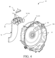
- the air outlet 11 is formed in a drum wall 12 and includes a plurality of sub-outlets 111.
- the plurality of sub-outlets 111 jointly form the air outlet 11, so that a large air outlet can be implemented while the mechanical performance such as strength and stiffness of the drum is ensured, to implement a large filter area.
- the large filter area can bring about a small air resistance and a low filter cleaning frequency, thereby improving drying efficiency and drying performance.
- each sub-outlet 111 is circumferentially closed and is formed through surrounding by the drum wall 12. That is, the plurality of sub-outlets 111 are independent of each other and are not in communication with each other, so that an impact on mechanical performance of the drum can be effectively reduced.
- the plurality of sub-outlets 111 may be partially in communication or constructed in another manner. More specifically, the air outlet 11 is disposed on a rear wall 121 of the drum 10. A plurality of reinforcing ribs 13 (which may be uniformly distributed or centrosymmetric) are disposed on a side of the rear wall 121 of the drum 10 facing outside the drum 10 in a radial direction and circumferential direction. The reinforcing ribs 13 are criss-crossed to form a plurality of accommodating regions C.
- Each of the plurality of sub-outlets 111 is formed in the rear wall 121 at a position corresponding to one of the plurality of accommodating regions C, to effectively use spaces between the reinforcing ribs without affecting the effect of enhancing the strength of the drum by the reinforcing ribs.
- the air outlet 11 includes four sub-outlets. The four sub-outlets are formed at corresponding positions that are located in the same circumferential direction, are adjacent in the radial direction, and accommodate regions C1 to C4. As an optional implementation, a quantity and specific positions of the sub-outlets 111 may use another arrangement. The air outlet 11 may be disposed at another position, for example, in a circumferential wall 122 of the drum 10.
- the drum 10 further includes a connecting portion 70 in communication with the air outlet 11.
- the connecting portion 70 is disposed outside the drum 10 and includes an inlet end 71, an outlet end 72, and a channel 73 that communicates the inlet end 71 and the outlet end 72.
- the inlet end 71 is in communication with each of the plurality of sub-outlets 111.
- the outlet end 72 is in communication with one end of the drying air channel P, and the other end of the drying air channel P is in communication with an air inlet (not shown in the figure) in the drum 10.
- a seal member 74 may be further disposed between the air outlet 11 and the connecting portion 70 for sealing.
- the channel 73 extends basically in parallel to the rear wall 121 of the drum 10.
- the inlet end 71 includes a plurality of sub-inlets 711.
- the plurality of sub-inlets 711 correspond one to one to and are respectively in communication with the plurality of sub-outlets 111.
- the channel 73 is in communication with each of the plurality of sub-inlets 711 and the outlet end 72.
- each of the plurality of sub-inlets 711 is formed through surrounding by a circumferentially closed wall W, and each of the plurality of sub-inlets 711 is inserted into a reinforcing rib 13 forming a corresponding accommodating region C1 to C4 to be in communication with a corresponding sub-outlet 111.
- the seal member 74 is constructed as a plurality of independent sub-seal members 741.
- One sub-seal member 741 is disposed between each sub-inlet 711 and a corresponding sub-outlet 111.
- Each sub-inlet 711 and a reinforcing rib 13 that forms a corresponding accommodating region C1 to C4 may cooperate with each other in the circumferential direction.
- Each sub-seal member 741 is disposed between a wall W of a corresponding sub-inlet 711 and a reinforcing rib 13. That is, a side seal is formed between each sub-inlet 711 and a reinforcing rib 13 that forms a corresponding accommodating region C1 to C4.
- Each sub-seal member 741 is disposed between an edge 14 and an end surface of a corresponding sub-inlet 711. That is, an end surface seal is formed between each sub-inlet 711 and a corresponding sub-outlet 111.
- the channel 73 may use another arrangement manner according to a specific arrangement of the drying air channel P.
- the inlet end 71 may be formed by a single inlet, and is in communication with each of the plurality of sub-outlets 111, and one seal member 71 is provided.
- the connecting portion 70 is integrally formed with the drying air channel P.
- the filter 50 may include a plurality of sub-filtering regions 51, and the plurality of sub-filtering regions 51 correspond one to one to the plurality of sub-outlets 111.
- the filter 50 may further include a plurality of independent sub-filters, and each sub-filter forms one sub-filtering region 51.
- the filter 50 is disposed at a position corresponding to the air outlet 11 in the drum 10, for example, is mounted at a position corresponding to the air outlet 11 on the drum wall 12.
- An end surface 501 of the filter 50 on an upstream side of a drying air flow direction is flush with an inner circumferential surface 15 of the drum wall 12 in which the filter 50 is mounted or is concave in the inner circumferential surface 15, to avoid forming interference with other members in the drum 10.
- the filter 50 may be disposed outside the drum 10, for example, disposed between the drum 10 and the connecting portion 70 or in the connecting portion 70; or may be disposed in the air outlet 11.
- one filter 50 is disposed in the drum wall 12 in which each sub-outlet 111 is formed.
- the filter 50 may be integrally formed with a part of the drum 10 in which the air outlet 11 is formed or the connecting portion 70 through integral injection molding.
- the filter 50 may further include a frame (not shown in the figure).
- the frame may be used for supporting and mounting the filter 50.
- a mesh portion is integrally formed with the frame through integral injection molding, or is mounted on the frame, for example, is inserted in the frame through the edge.
- the mesh portion may be made of metal, the frame may be made of plastic, and the part of the drum 10 in which the air outlet 11 is formed is made of plastic.
- the drum 10 further includes a filter cleaning portion 80, and the filter cleaning portion 80 supplies a cleaning medium used for cleaning the filter 50 to the filter 50.
- the filter cleaning portion 80 is disposed, and the filter is cleaned regularly or as required by using the cleaning medium, so that smooth passage of drying air can be ensured, and after a drying procedure is run for a period of time, blockage of the filter is avoided, the drying performance or efficiency is kept from being reduced, and the drying procedure is not affected.
- the filter cleaning portion 80 includes a water dispenser 81 and a plurality of spouts 82 provided in the water dispenser 81.
- the water dispenser 81 is in communication with the cleaning medium and sprays the cleaning medium through the plurality of spouts 82 to separate flint from the filter 50.
- the dryer 100 includes a cleaning pipe (not shown in the figure, which may be a water inlet pipe, a water condensation pipe, or the like) for providing the cleaning medium.
- the water dispenser 81 is connected to the cleaning pipe.
- the spouts 82 are provided in a downstream side of a drying air flow direction relative to the filter 50 and sprays the cleaning medium to a surface of the filter 50.
- the filter cleaning portion 80 is mounted on a downstream side relative to a drying air flow direction of the inlet end 71 as a whole from an opening 74 in the connecting portion 70, and the spouts 82 face the inlet end 71 of the connecting portion 70.
- the spouts 82 include a plurality of regions, and each region corresponds to one sub-filtering region 51 of the filter 50, to spray the cleaning medium to the corresponding sub-filtering region 51.
- the dryer 100 may further include a cleaning control module (not shown in the figure) configured to control cleaning of the filter cleaning portion 80, for example, control a time and manner of spraying the cleaning medium to the filter 50; or the filter cleaning portion 80 may not be disposed, and the filter is cleaned by manually dissembling the filter or in another manner.
Landscapes
- Engineering & Computer Science (AREA)
- Textile Engineering (AREA)
- Detail Structures Of Washing Machines And Dryers (AREA)
Applications Claiming Priority (1)
| Application Number | Priority Date | Filing Date | Title |
|---|---|---|---|
| CN202310166291.0A CN118547478A (zh) | 2023-02-24 | 2023-02-24 | 干衣机的桶及具有该桶的干衣机 |
Publications (1)
| Publication Number | Publication Date |
|---|---|
| EP4421233A1 true EP4421233A1 (fr) | 2024-08-28 |
Family
ID=89715632
Family Applications (1)
| Application Number | Title | Priority Date | Filing Date |
|---|---|---|---|
| EP24153690.3A Pending EP4421233A1 (fr) | 2023-02-24 | 2024-01-24 | Tambour pour sèche-linge et sèche-linge doté du tambour |
Country Status (2)
| Country | Link |
|---|---|
| EP (1) | EP4421233A1 (fr) |
| CN (1) | CN118547478A (fr) |
Citations (4)
| Publication number | Priority date | Publication date | Assignee | Title |
|---|---|---|---|---|
| US5701684A (en) * | 1993-09-15 | 1997-12-30 | Fisher & Paykel Limited | Lint collector for clothes drier |
| WO2005017249A1 (fr) * | 2003-08-15 | 2005-02-24 | Arcelik Anonim Sirketi | Lave-linge sechant equipe d'un tambour comprenant un ou plusieurs filtres |
| WO2010137910A2 (fr) * | 2009-05-28 | 2010-12-02 | Lg Electronics Inc. | Machine à laver possédant une fonction de séchage |
| WO2019210747A1 (fr) * | 2018-05-01 | 2019-11-07 | 青岛海尔洗衣机有限公司 | Lave-linge/sèche-linge combiné |
-
2023
- 2023-02-24 CN CN202310166291.0A patent/CN118547478A/zh active Pending
-
2024
- 2024-01-24 EP EP24153690.3A patent/EP4421233A1/fr active Pending
Patent Citations (4)
| Publication number | Priority date | Publication date | Assignee | Title |
|---|---|---|---|---|
| US5701684A (en) * | 1993-09-15 | 1997-12-30 | Fisher & Paykel Limited | Lint collector for clothes drier |
| WO2005017249A1 (fr) * | 2003-08-15 | 2005-02-24 | Arcelik Anonim Sirketi | Lave-linge sechant equipe d'un tambour comprenant un ou plusieurs filtres |
| WO2010137910A2 (fr) * | 2009-05-28 | 2010-12-02 | Lg Electronics Inc. | Machine à laver possédant une fonction de séchage |
| WO2019210747A1 (fr) * | 2018-05-01 | 2019-11-07 | 青岛海尔洗衣机有限公司 | Lave-linge/sèche-linge combiné |
Also Published As
| Publication number | Publication date |
|---|---|
| CN118547478A (zh) | 2024-08-27 |
Similar Documents
| Publication | Publication Date | Title |
|---|---|---|
| US10087569B2 (en) | Maintenance free dryer having multiple self-cleaning lint filters | |
| US8056254B2 (en) | Tumble dryer with a lint filter | |
| US7866057B2 (en) | Domestic appliance for the care of washed articles | |
| US8266813B2 (en) | Exhaust air dryer with heat exchanger | |
| EP1936022A1 (fr) | Sèche-linge | |
| RU2533712C1 (ru) | Устройство обработки одежды, содержащее устройство очистки теплообменника | |
| EP0816549B1 (fr) | Machine à laver domestique comportant un circuit fermé de séchage, un système de condensation de la vapeur et un filtre auto-nettoyant | |
| US20130180553A1 (en) | Dishwasher | |
| EP3282049B1 (fr) | Séchoir sans maintenance comportant de multiples filtres à peluches autonettoyants | |
| EP2573253B1 (fr) | Sèche-linge à pompe à chaleur | |
| AU2021299595B2 (en) | Laundry treatment machine | |
| US9526395B2 (en) | Automatic dishwasher | |
| KR20220004528A (ko) | 세탁물 처리기기 | |
| EP4421233A1 (fr) | Tambour pour sèche-linge et sèche-linge doté du tambour | |
| KR101825448B1 (ko) | 열교환기 세척노즐 및 그를 이용한 열교환기의 세척 장치 | |
| WO2015118585A1 (fr) | Lave-linge/sèche-linge | |
| CN107923116B (zh) | 具有用于热交换器的清洁装置的家用器具 | |
| KR101825449B1 (ko) | 열교환기 세척노즐 및 그를 이용한 열교환기의 세척 장치 | |
| CN115704174A (zh) | 衣物处理设备及控制方法 | |
| US20240318367A1 (en) | Laundry treating apparatus | |
| KR20220005337A (ko) | 세탁물 처리기기 | |
| CN118223273A (zh) | 干衣机及其毛絮处理装置 | |
| JPH1176131A (ja) | 食器洗浄機 | |
| KR20220135096A (ko) | 세탁물 처리기기 | |
| CN117587622A (zh) | 用于操作具有热泵和清洁装置的干燥设备的方法 |
Legal Events
| Date | Code | Title | Description |
|---|---|---|---|
| PUAI | Public reference made under article 153(3) epc to a published international application that has entered the european phase |
Free format text: ORIGINAL CODE: 0009012 |
|
| STAA | Information on the status of an ep patent application or granted ep patent |
Free format text: STATUS: THE APPLICATION HAS BEEN PUBLISHED |
|
| AK | Designated contracting states |
Kind code of ref document: A1 Designated state(s): AL AT BE BG CH CY CZ DE DK EE ES FI FR GB GR HR HU IE IS IT LI LT LU LV MC ME MK MT NL NO PL PT RO RS SE SI SK SM TR |