EP4417954A1 - Antistatisches druckmessrechen - Google Patents
Antistatisches druckmessrechen Download PDFInfo
- Publication number
- EP4417954A1 EP4417954A1 EP24156492.1A EP24156492A EP4417954A1 EP 4417954 A1 EP4417954 A1 EP 4417954A1 EP 24156492 A EP24156492 A EP 24156492A EP 4417954 A1 EP4417954 A1 EP 4417954A1
- Authority
- EP
- European Patent Office
- Prior art keywords
- sheath
- conductive
- conductive layer
- measuring rake
- connecting rod
- Prior art date
- Legal status (The legal status is an assumption and is not a legal conclusion. Google has not performed a legal analysis and makes no representation as to the accuracy of the status listed.)
- Pending
Links
Images


Classifications
-
- G—PHYSICS
- G01—MEASURING; TESTING
- G01L—MEASURING FORCE, STRESS, TORQUE, WORK, MECHANICAL POWER, MECHANICAL EFFICIENCY, OR FLUID PRESSURE
- G01L23/00—Devices or apparatus for measuring or indicating or recording rapid changes, such as oscillations, in the pressure of steam, gas, or liquid; Indicators for determining work or energy of steam, internal-combustion, or other fluid-pressure engines from the condition of the working fluid
- G01L23/26—Details or accessories
-
- G—PHYSICS
- G01—MEASURING; TESTING
- G01M—TESTING STATIC OR DYNAMIC BALANCE OF MACHINES OR STRUCTURES; TESTING OF STRUCTURES OR APPARATUS, NOT OTHERWISE PROVIDED FOR
- G01M15/00—Testing of engines
- G01M15/14—Testing gas-turbine engines or jet-propulsion engines
-
- F—MECHANICAL ENGINEERING; LIGHTING; HEATING; WEAPONS; BLASTING
- F02—COMBUSTION ENGINES; HOT-GAS OR COMBUSTION-PRODUCT ENGINE PLANTS
- F02K—JET-PROPULSION PLANTS
- F02K1/00—Plants characterised by the form or arrangement of the jet pipe or nozzle; Jet pipes or nozzles peculiar thereto
- F02K1/54—Nozzles having means for reversing jet thrust
- F02K1/76—Control or regulation of thrust reversers
- F02K1/763—Control or regulation of thrust reversers with actuating systems or actuating devices; Arrangement of actuators for thrust reversers
-
- B—PERFORMING OPERATIONS; TRANSPORTING
- B64—AIRCRAFT; AVIATION; COSMONAUTICS
- B64D—EQUIPMENT FOR FITTING IN OR TO AIRCRAFT; FLIGHT SUITS; PARACHUTES; ARRANGEMENT OR MOUNTING OF POWER PLANTS OR PROPULSION TRANSMISSIONS IN AIRCRAFT
- B64D45/00—Aircraft indicators or protectors not otherwise provided for
-
- B—PERFORMING OPERATIONS; TRANSPORTING
- B64—AIRCRAFT; AVIATION; COSMONAUTICS
- B64F—GROUND OR AIRCRAFT-CARRIER-DECK INSTALLATIONS SPECIALLY ADAPTED FOR USE IN CONNECTION WITH AIRCRAFT; DESIGNING, MANUFACTURING, ASSEMBLING, CLEANING, MAINTAINING OR REPAIRING AIRCRAFT, NOT OTHERWISE PROVIDED FOR; HANDLING, TRANSPORTING, TESTING OR INSPECTING AIRCRAFT COMPONENTS, NOT OTHERWISE PROVIDED FOR
- B64F5/00—Designing, manufacturing, assembling, cleaning, maintaining or repairing aircraft, not otherwise provided for; Handling, transporting, testing or inspecting aircraft components, not otherwise provided for
- B64F5/60—Testing or inspecting aircraft components or systems
-
- F—MECHANICAL ENGINEERING; LIGHTING; HEATING; WEAPONS; BLASTING
- F01—MACHINES OR ENGINES IN GENERAL; ENGINE PLANTS IN GENERAL; STEAM ENGINES
- F01D—NON-POSITIVE DISPLACEMENT MACHINES OR ENGINES, e.g. STEAM TURBINES
- F01D17/00—Regulating or controlling by varying flow
- F01D17/02—Arrangement of sensing elements
- F01D17/08—Arrangement of sensing elements responsive to condition of working-fluid, e.g. pressure
-
- F—MECHANICAL ENGINEERING; LIGHTING; HEATING; WEAPONS; BLASTING
- F02—COMBUSTION ENGINES; HOT-GAS OR COMBUSTION-PRODUCT ENGINE PLANTS
- F02K—JET-PROPULSION PLANTS
- F02K1/00—Plants characterised by the form or arrangement of the jet pipe or nozzle; Jet pipes or nozzles peculiar thereto
- F02K1/54—Nozzles having means for reversing jet thrust
- F02K1/56—Reversing jet main flow
- F02K1/60—Reversing jet main flow by blocking the rearward discharge by means of pivoted eyelids or clamshells, e.g. target-type reversers
- F02K1/605—Reversing jet main flow by blocking the rearward discharge by means of pivoted eyelids or clamshells, e.g. target-type reversers the aft end of the engine cowling being movable to uncover openings for the reversed flow
-
- G—PHYSICS
- G01—MEASURING; TESTING
- G01L—MEASURING FORCE, STRESS, TORQUE, WORK, MECHANICAL POWER, MECHANICAL EFFICIENCY, OR FLUID PRESSURE
- G01L15/00—Devices or apparatus for measuring two or more fluid pressure values simultaneously
-
- G—PHYSICS
- G01—MEASURING; TESTING
- G01L—MEASURING FORCE, STRESS, TORQUE, WORK, MECHANICAL POWER, MECHANICAL EFFICIENCY, OR FLUID PRESSURE
- G01L19/00—Details of, or accessories for, apparatus for measuring steady or quasi-steady pressure of a fluent medium insofar as such details or accessories are not special to particular types of pressure gauges
-
- G—PHYSICS
- G01—MEASURING; TESTING
- G01L—MEASURING FORCE, STRESS, TORQUE, WORK, MECHANICAL POWER, MECHANICAL EFFICIENCY, OR FLUID PRESSURE
- G01L23/00—Devices or apparatus for measuring or indicating or recording rapid changes, such as oscillations, in the pressure of steam, gas, or liquid; Indicators for determining work or energy of steam, internal-combustion, or other fluid-pressure engines from the condition of the working fluid
- G01L23/24—Devices or apparatus for measuring or indicating or recording rapid changes, such as oscillations, in the pressure of steam, gas, or liquid; Indicators for determining work or energy of steam, internal-combustion, or other fluid-pressure engines from the condition of the working fluid specially adapted for measuring pressure in inlet or exhaust ducts of internal-combustion engines
-
- H—ELECTRICITY
- H05—ELECTRIC TECHNIQUES NOT OTHERWISE PROVIDED FOR
- H05F—STATIC ELECTRICITY; NATURALLY-OCCURRING ELECTRICITY
- H05F1/00—Preventing the formation of electrostatic charges
-
- F—MECHANICAL ENGINEERING; LIGHTING; HEATING; WEAPONS; BLASTING
- F05—INDEXING SCHEMES RELATING TO ENGINES OR PUMPS IN VARIOUS SUBCLASSES OF CLASSES F01-F04
- F05D—INDEXING SCHEME FOR ASPECTS RELATING TO NON-POSITIVE-DISPLACEMENT MACHINES OR ENGINES, GAS-TURBINES OR JET-PROPULSION PLANTS
- F05D2300/00—Materials; Properties thereof
- F05D2300/10—Metals, alloys or intermetallic compounds
Definitions
- the present invention relates to an antistatic pressure measuring rake, in particular for an aircraft engine, and more particularly for a dual-flow turbojet.
- the engines of said aircraft are likely to be tested. These tests require measurements to be taken, on the ground and/or in flight, at different locations on the engine to be tested. These measurements involve instrumentation of the engine, in particular at the level of the interior of a secondary vein. For this, we know, for example from the document FR 3 090 102 A1 , measuring tools for taking pressure measurements in an aircraft engine.
- measuring tools are arranged in air flow circulation areas and are therefore subjected to friction forces that can generate electrostatic charges.
- measuring tools are generally made of insulating materials, in particular to prevent moisture infiltration that could freeze at high altitude and damage the measuring tool.
- Such measuring tools do not allow electrostatic charges to be dissipated, and they therefore accumulate on the surfaces of the measuring tool. Beyond a certain limit, these electrostatic charges can dissipate suddenly, creating an electrical discharge that can disrupt measurements and electronic communications.
- the present invention aims to remedy the aforementioned drawbacks. It relates to an antistatic pressure measuring rake, in particular for an aircraft engine, and more particularly for a dual-flow turbojet.
- a simple and inexpensive measuring tool which does not accumulate electrostatic charges, in particular when subjected to an air flow, and which therefore makes it possible to avoid problems caused by electrostatic discharges, in particular disturbances of the measurements taken by the sensors and/or disturbances of the electrical communications between the sensors and a data processing unit.
- the conductive layer corresponds to a layer of conductive paint with which at least part of the sheath is painted.
- the conductive layer comprises at least one antistatic agent made from one of the following chemical elements: copper, carbon, nickel, silver, silicates, indium.
- the measuring rake further comprises at least one conductive blade intended to permanently electrically connect the conductive layer to at least one conductive element.
- the conductive blade comprises a fixing end fixed in the housing of the sheath in contact with the conductive layer and a free end projecting from the housing at a longitudinal end of the sheath, the free end being intended to electrically connect, permanently, the conductive layer to at least one conductive element by being permanently pressed against said conductive element.
- the conductive blade has a rigidity and an arrangement intended to permanently create an elastic force against the conductive element at the free end, said elastic force being capable of maintaining contact between said free end and said conductive element so as to permanently electrically connect the conductive layer to said conductive element.
- the measuring rake further comprises an attached leading edge removably attached to the sheath by means of a counter-plate arranged in the housing, said attached leading edge and said counter-plate being arranged on either side of a front wall of the sheath and attached together to said sheath so as to both be electrically connected to the conductive layer, the conductive blade being attached, at its attachment end, to the counter-plate.
- the measuring rake comprises at least one data processing unit capable of receiving data measured by the sensors of the electronic circuit, said data processing unit being arranged on the sheath or remote.
- the present invention also relates to an engine of an aircraft.
- the engine comprises a secondary vein and at least one movable reversing door, said reversing door comprising at least one fixed connecting rod articulated between the reversing door and a motorization, said connecting rod being configured to allow the reversing door to be brought into a retracted position in which it is not across the secondary vein and into a deployed position in which it is across the secondary vein, said engine comprising at least one measuring rack as described above arranged on at least one connecting rod of the engine, the connecting rod(s) each being housed in the housing of at least one measuring rack.
- the present invention also relates to an aircraft comprising at least one engine as described above.
- the pressure measuring rake 1 (hereinafter measuring rake 1) for illustrating the invention is shown in particular embodiments of the figure 2 to the figure 6 . It corresponds to a measuring tool for carrying out aerodynamic measurements, in particular pressure measurements.
- the measuring rake 1 is particularly suitable for use on an AC aircraft, shown in the figure 1 . It allows measurements to be carried out in the context of ground and/or flight tests.
- the measuring rake 1 is arranged in a vein of an engine 2 of the aircraft AC, as shown in the figure 2 and the figure 3 .
- the aircraft AC comprises a fuselage 3 on each side of which is fixed a wing 4 carrying an engine 2 fixed to a mast 5 located under said wing 4.
- the engine 2 corresponds to a dual-flow turbojet and the measuring rake 1 is configured to carry out pressure measurements in a secondary vein 6 of said engine 2.
- the invention is not limited to such an engine and the measuring rake 1 can be used in a large number of different and varied situations in which the pressure of an air flow must be measured.
- the engine 2 comprises a fan 7, a motorization 8 forming a core, and a nacelle 9 arranged around the motorization 8.
- the secondary vein 6 is delimited between the motorization 8 and the nacelle 9.
- the air enters through the fan 7 then it is divided into a primary flow which passes through the motorization 8 and into a secondary flow which passes through the secondary vein 6, as represented by arrows F on the figure 2 and the figure 3 .
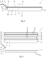
- the engine 2 also includes a thrust reverser system which comprises reverser doors 10.
- These reverser doors 10 are mounted to be able to rotate about an axis substantially perpendicular to the X axis, or parallel to the Y axis. They can be brought into a retracted position ( figure 2 ), corresponding to a configuration where engine 2 is in thrust mode, and in a deployed position ( figure 3 ), corresponding to a configuration where the engine 2 is in counter-thrust mode.
- the reversing doors 10 are included in the walls of the nacelle 9, they are not across the secondary vein 6, and they therefore do not obstruct the passage of the secondary air flow.
- the reversing doors 10 In the deployed position, the reversing doors 10 extend from the motorization 8 to the walls of the nacelle 9, they are across the secondary vein 6, and they therefore obstruct the passage of the secondary air flow. In addition, in this deployed position, the reversing doors 10 open windows 11 which communicate with the outside of the nacelle 9 and allow the secondary air flow to be deflected by said windows 11.
- each connecting rod 12 comprises a body 14 ( figure 6 ) provided with an elongated shape extending between the motorization 8 and the reversing door 10 on which it is arranged.
- a longitudinal end 15 of each connecting rod 12 is fixed in an articulated manner to the reversing door 10 and another longitudinal end 16 of each connecting rod 12 is fixed to the motorization 8.
- the body 14 of each connecting rod 12 has an aerodynamic section around which the secondary air flow of the secondary vein 6 flows.
- the motor 2 also includes standard movement elements (jacks, slides, etc.) making it possible to bring the reversing doors 10 into the retracted position and into the deployed position by means of the connecting rods 12.
- the connecting rods 12 are across the secondary airflow 6, namely they are oriented so that their longitudinal direction is substantially incident to the secondary airflow. Conversely, in the deployed position, the connecting rods 12 are not across the secondary airflow 6, namely they are oriented so that their longitudinal direction is substantially in the direction of the secondary airflow.
- the measuring rake 1 is arranged on a connecting rod 12 of the engine 2, however, in other embodiments, it can be configured to be arranged on another element of the engine 2 or of the aircraft AC.
- the measuring rake 1 is configured to allow pressure measurements of the air flow in the secondary vein 6 to be carried out, in particular when the reversing door 10 is in the retracted position. In this configuration, the measuring rake 1 is subjected to friction from the air flow which is likely to generate electrostatic charges on external surfaces of the measuring rake 1.
- the measuring rake 1 is special in that it includes a conductive layer 37, shown schematically in the figure 4 to the figure 6 , which is capable of conducting electrostatic charges likely to be generated and accumulate on surfaces of said measuring rake 1. In doing so, the conductive layer 37 allows these electrostatic charges to be drained by a third element, as described in more detail below in the description.
- the measuring rake 1 shown in the figure 4 to the figure 6 , is a measuring tool comprising several elements which are assembled and fixed together “in a sandwich”, as illustrated in the exploded view of the figure 5 .
- the arrangement of these elements is described in more detail in the following description.
- the measuring rake 1 comprises, in particular, a sheath 17 which is arranged and fixed on the body 14 of the connecting rod 12 which it is desired to instrument.
- This sheath 17 has an elongated shape and an aerodynamic profile, for example a biconvex profile.
- the sheath 17 is produced by three-dimensional printing in a polymer-type material, for example polyamide.
- the measuring rake 1 has a length capable of covering, at least in part, the entirety of the connecting rod 12.
- the measuring rake 1 typically has a length of between 50 cm and 1 m, in particular a length of 80 cm.
- the sheath 17 comprises two side walls 18A and 18B delimiting, between them, a housing 19 configured to receive the body 14 of the connecting rod 12.
- the housing 19 communicates with the outside of the sheath 17 by a slot 20 which extends over the length of the sheath 17 between the side walls 18A and 18B. These thus form a clamp making it possible to grip the body 14 of the connecting rod 12.
- the sheath 17 is open at longitudinal ends 21 and 22, which allows the longitudinal ends 15 and 16 of the connecting rod 12 to protrude from said sheath 17 in order to be fixed, respectively, to the motorization 8 and to the reversing door 10.
- the slot 20 is narrower than the thickness of the body 14 of the connecting rod 12 and the introduction of said connecting rod 12 therefore requires an elastic spacing of the side walls 18A and 18B for the positioning of the measuring rake 1 on the connecting rod 12.
- the body 14 may, however, comprise shapes or elements (not shown) to facilitate the positioning of the measuring rake 1 and/or to prevent the movement of the sleeve 17 along the connecting rod 12.
- the side walls 18A and 18B may be held clamped together on the body 14 of the connecting rod 12 by means of a removable fastener (not shown).
- a removable fastener for example, they may be screwed, bolted, glued or clamped by a clamp.
- the sheath 17 has, when it is in place on the connecting rod 12 in the secondary vein 6, a leading edge 23 oriented towards the front (positively along the X axis) and a trailing edge 24 oriented towards the rear (negatively along the X axis) relative to the flow of air in the secondary vein 6.
- the sheath 17 is configured so that the slot 20 is located at the trailing edge 24.
- the measuring rake 1 comprises an electronic circuit 25 arranged on the sheath 17.
- This electronic circuit 25 is, in particular, provided with a face 26 arranged on a front face 27 of the sheath 17.
- the front face 27 corresponds to a surface located on the side of the leading edge 23 which extends over the length of said sheath 17.
- the electronic circuit 25 is also provided with a face 28, opposite the face 26 and therefore oriented towards the leading edge 23, on which a plurality of pressure sensors 29 are arranged.
- the electronic circuit 25 corresponds to a printed circuit having an elongated shape and it is arranged over the entire length of the front face 27.
- it may be another type of electronic circuit extending over all or part of the front face 27.
- the sensors 29 are distributed so as to form a line extending over the length of the electronic circuit 25.
- the electronic circuit 25 also comprises a data bus allowing incoming and/or outgoing data communications with the sensors 29 as well as a power supply.
- the sensors 29 are configured to measure pressure values generated by the secondary air flow of the secondary vein 6, as specified below in the description.
- the sensors 29 correspond to pressure sensors of the microelectromechanical system type (also called MEMS for “MicroElectroMechanical Systems” in English).
- MEMS MicroElectromechanical System
- they may be sensors of another type capable of carrying out pressure measurements.
- the “MEMS” sensors which are particularly compact, make it possible to obtain a line of sensors 29 along the electronic circuit 25 with a density of fifty sensors per meter, which represents one sensor every 20 mm.
- the sensor density can vary, for example with a distance between two sensors 29 of between 10 mm and 100 mm.
- the measuring rake 1 comprises a data processing unit 30, shown schematically in the figure 5 .
- the data processing unit 30 is connected to the electronic circuit 25 so as to be able to receive data measured by the sensors 29 of said electronic circuit 25.
- the data processing unit 30 can be configured to provide a function of acquiring and transmitting the data measured by the sensors 29 and/or a recording function, for example in a memory (not shown).
- the data processing unit 30 is integrated directly on the measuring rake 1, for example in a part of the sheath 17.
- the data processing unit 30 can be offset elsewhere. For example, it can be arranged on a part of the motor 2, on or under the reversing door 10.
- the measuring rake 1 may comprise a foot (not shown in the figures) arranged at one end of the sheath 17.
- the foot has a planar shape.
- the foot is configured to protect the data processing unit 30 in the case where the latter is arranged on the measuring rake 1.
- the foot is capable of being pressed against the inversion door 10 so as to cover the data processing unit 30 to protect it from the external environment.
- the measuring rake 1 also comprises a leading edge 31 attached to the front face 27 of the sheath 17 so as to cover the electronic circuit 25.
- the measuring rake 1 may comprise a leading edge directly integrated into the shape of the sheath 17.
- the added leading edge 31 corresponds to a single-piece part fixed to the sheath 17 in a removable manner, for example using screws. It can be produced by machining in a metallic material. In particular, it is produced in an electrically conductive material, preferably aluminum.
- the added leading edge 31 comprises an internal face 32 arranged on the front face 27 of the sheath 17 so as to cover the electronic circuit 25. It also comprises an external face 33 opposite said internal face 32. As illustrated in the figure 4 , the external face 33 is located towards the leading edge 23 of the sheath 17 and it has a rounded shape intended to be incident to the secondary air flow.
- the leading edge 31 further comprises a plurality of air intakes 34 distributed along the length of said added leading edge 31.
- the air intakes 34 are distributed at regular intervals, that is to say at the same distance from each other. However, they can also be distributed at irregular intervals.
- Each air intake 34 forms a fluid passage between the external face 33 and the internal face 32.
- These air intakes 34 have an end 35 opening via the external face 33 into the secondary vein 6 and an end 36 opening via the internal face 32 onto the electronic circuit 25.
- each air intake 34 opens via the end 36 opposite a sensor 29 of the electronic circuit 25.
- the measuring rake 1 comprises a seal 49 arranged between the added leading edge 31 and the electronic circuit 25.
- the seal 49 is pressed between the internal face 32 of the added leading edge 31 and the face 28 of the electronic circuit 25 so as to ensure a seal at the interface.
- the seal 49 comprises openings allowing each air intake 34 to open onto a sensor 29.
- each sensor 29 can measure a pressure of the air flow of the secondary vein 6 channeled by a particular air intake 34.
- each air intake 34 can open opposite a plurality of sensors 29, so as to carry out several measurements linked to an air flow channeled by an air intake 34.
- the measuring rake 1 comprises the conductive layer 37 covering the sheath 17.
- the conductive layer 37 completely covers all the surfaces of the sheath 17.
- the conductive layer 37 can partially cover the surfaces of the sheath 17, for example only the surfaces subjected to the air flow of the secondary vein 6.
- the conductive layer 17 is a durable coating layer having electrical conduction properties that are also durable.
- durable it is meant that the conductive layer 37 is a layer that does not flake or peel off over time, particularly when subjected to airflow.
- the conductive layer 37 is a layer that maintains unchanged electrical conduction properties over time, particularly when subjected to airflow.
- the measuring rake 1 is configured such that the conductive layer 37 is electrically connected, permanently, to a conductive element configured to drain charges likely to accumulate on the conductive layer 37.
- this conductive element corresponds to a conductive element of the motor 2.
- This connection is configured to allow the conductive layer to discharge, namely that electrostatic charges present on the conductive layer 37 can be drained by the conductive element of the engine 2.
- the sheath 17 can have a suitable shape allowing, when the measuring rake 1 is mounted on the connecting rod 12, said sheath 17 to be in contact with the nacelle 9 or the reversing door 10.
- the sheath 17 being covered with the conductive layer 37, this contact makes it possible to obtain an electrical connection capable of draining electrostatic charges.
- the conductive layer 37 may be connected to a conductive element of the motor 2 via other elements.
- a simple and inexpensive measuring tool which does not accumulate electrostatic charges, in particular when it is subjected to an air flow.
- Such a measuring rake 1 therefore makes it possible to avoid problems caused by electrostatic discharges. In particular, it makes it possible to avoid disturbances of measurements taken by the sensors 29 and/or disturbances of electrical communications between the sensors 29 and the data processing unit 30.
- the conductive layer 37 corresponds to a layer of conductive paint. It may be a paint comprising a resin into which charged particles have been introduced, for example in the form of a metal powder. These may be antistatic paints used in certain industrial environments or in the naval field.
- the sheath 17 may be entirely painted using such a conductive paint, or be painted only on its surfaces subjected to the air flow of the secondary vein 6.
- the conductive paint composing the conductive layer 37 may comprise antistatic agents made from at least one of the following chemical elements: copper, carbon, nickel, silver, silicates, indium. These chemical elements may in particular be in the form of oxides.
- the measuring rake also comprises a conductive blade 38. It is configured to permanently electrically connect the conductive layer 37 to a conductive element of the engine 2.
- the conductive blade 38 can be configured so as to be in contact, both with the conductive layer 37 and with the nacelle 9 or the reversing door 10 of the engine 2, when the measuring rake 1 is installed on the connecting rod 12. In this way, a connection with a conductive element of the engine 2, making it possible to drain the electrostatic charges which may be generated on the conductive layer 37, is permanently ensured by a dedicated element, namely the conductive blade 38.
- the conductive blade 38 is made of an electrically conductive metallic material, preferably aluminum. It has a shape, and in particular a thickness, allowing it to be sufficiently rigid to ensure permanent contact, without being detached by an external element, for example by the air flow of the secondary vein 6. Depending on the material, the necessary thickness may vary. As a non-limiting example, for a blade made of aluminum, an appropriate thickness may be at least 1 mm.
- the conductive blade 38 can have various shapes adapted to many configurations. In addition, it is easily removable, so it is possible to have a plurality of conductive blades 38 from which one is chosen that has a shape adapted to a given configuration. For example, it is possible to have conductive blades 38 of more or less length large depending on whether we wish to connect the measuring rake to a conductive element more or less distant from the latter.
- the conductive blade 38 comprises a fixing end 39 fixed in the housing 19 of the sheath 17. This fixing is configured to obtain an electrically conductive contact between the conductive blade 38 and the conductive layer 37.
- the conductive blade 38 also comprises a free end 40 projecting from the housing 19 at the longitudinal end 21 of the sheath 17. This free end 40 is configured to be permanently pressed against a conductive element of the engine 2 when the measuring rake 1 is installed on the connecting rod 12.
- the conductive blade 38 is configured so as to have a rigidity and an arrangement (relative to the part of the motor 2 on which it must be pressed) capable of creating an elastic force at the free end 40 against the conductive element of the motor 2 to which it is desired to electrically connect it.
- This elastic force represented schematically by an arrow E on the figure 4 , is capable of maintaining permanent contact between the free end 40 and the conductive element of the engine 2 when the measuring rake 1 is installed on the connecting rod 12.
- the foot can be arranged at the longitudinal end 21 of the sheath 17.
- the foot is configured to ensure the plating of the conductive blade 38 against an element of the engine 2.
- the conductive blade 38 is located between said element of the engine 2 (for example the reversing door 10) and the foot.
- the measuring rake 1 comprises the added leading edge 31 as described above in the present description.
- the latter is removably fixed to the sheath 17 by means of a counterplate 41 arranged in the housing 19 of the sheath 17.
- the counter plate-plate 41 is slid into a “T” shaped groove 48, which mechanically holds it in the sheath 17 and leaves access for inserting the screws 45.
- the counterplate 41 and the sheath 17 are provided, respectively, with through holes 46 and 47 intended to be aligned with each other. Screws 42 are arranged in these through holes 46 and 47 so as to protrude from the side of the front face 27 of the sheath 17. Furthermore, the added leading edge 31 has tapped holes 45 into which the screws 42 are capable of being screwed. Thus, the screws 42 make it possible to fix the added leading edge 31 to the sheath 17 by pressing it against the front face 27.
- the counterplate 41 extends over the entire length of the sheath so that the conductive blade 38 can be fixed to one of these ends. More precisely, the fixing end 39 of the conductive blade 38 is arranged against an end 43 of the counterplate 41 located at the longitudinal end 21 of the sheath 17. The fixing end 39 has a hole 44, shown schematically in the figure 5 , allowing the conductive blade 38 to be fixed to the counterplate 41 using a screw 42.
- the counterplate 41 is plated in the housing 19 of the sheath 17 which is covered by the conductive layer 37. As it is made of an electrically conductive metallic material, it allows the conductive layer 37 to be electrically connected to the conductive blade 38.
- the added leading edge 31 is also pressed against the front face 27 of the sheath 17 which is covered by the conductive layer 37. Consequently, electrostatic charges generated by the air flow of the secondary vein 6 on the added leading edge 31 can be drained via the conductive layer 37, via the counterplate 41 and via the conductive blade 38, by the conductive element of the motor 2 to which it is chosen to connect the measuring rake 1.
Landscapes
- Engineering & Computer Science (AREA)
- Chemical & Material Sciences (AREA)
- Combustion & Propulsion (AREA)
- Physics & Mathematics (AREA)
- General Physics & Mathematics (AREA)
- Mechanical Engineering (AREA)
- General Engineering & Computer Science (AREA)
- Aviation & Aerospace Engineering (AREA)
- Manufacturing & Machinery (AREA)
- Transportation (AREA)
- Measuring Fluid Pressure (AREA)
Applications Claiming Priority (1)
| Application Number | Priority Date | Filing Date | Title |
|---|---|---|---|
| FR2301497 | 2023-02-17 |
Publications (1)
| Publication Number | Publication Date |
|---|---|
| EP4417954A1 true EP4417954A1 (de) | 2024-08-21 |
Family
ID=86329239
Family Applications (1)
| Application Number | Title | Priority Date | Filing Date |
|---|---|---|---|
| EP24156492.1A Pending EP4417954A1 (de) | 2023-02-17 | 2024-02-08 | Antistatisches druckmessrechen |
Country Status (3)
| Country | Link |
|---|---|
| US (1) | US20240280439A1 (de) |
| EP (1) | EP4417954A1 (de) |
| CN (1) | CN118518252A (de) |
Citations (1)
| Publication number | Priority date | Publication date | Assignee | Title |
|---|---|---|---|---|
| FR3090102A1 (fr) | 2018-12-17 | 2020-06-19 | Airbus Operations | Outil de mesure de pression comportant un fourreau pour sa mise en place dans une veine d’un moteur d’aeronef |
Family Cites Families (35)
| Publication number | Priority date | Publication date | Assignee | Title |
|---|---|---|---|---|
| FR2634251B1 (fr) * | 1988-07-18 | 1993-08-13 | Hispano Suiza Sa | Inverseur de poussee de turboreacteur a double flux equipe de bords de deviation mobiles |
| JP3156320B2 (ja) * | 1990-12-27 | 2001-04-16 | ゼロックス コーポレーション | 反応性希釈剤中の活性ポリマーから製造したバインダー/生成層 |
| FR2683859B1 (fr) * | 1991-11-15 | 1994-02-18 | Hispano Suiza | Inverseur de poussee de turboreacteur a double flux. |
| FR2712929B1 (fr) * | 1993-11-24 | 1995-12-29 | Hispano Suiza Sa | Inverseur de poussée de turboréacteur à double flux. |
| US5478676A (en) * | 1994-08-02 | 1995-12-26 | Rexam Graphics | Current collector having a conductive primer layer |
| FR2748779B1 (fr) * | 1996-05-15 | 1998-06-19 | Hispano Suiza Sa | Inverseur de poussee de turboreacteur a portes associees a un panneau amont |
| FR2748778B1 (fr) * | 1996-05-15 | 1998-06-19 | Hispano Suiza Sa | Inverseur de poussee de turboreacteur a portes associees a un panneau amont |
| FR2752017B1 (fr) * | 1996-08-01 | 1998-10-16 | Hispano Suiza Sa | Inverseur de poussee de turboreacteur a portes formant ecopes |
| US6595062B1 (en) * | 2000-10-16 | 2003-07-22 | Lockheed Martin Corporation | High temperature rake for suspersonic flow |
| US7608342B2 (en) * | 2005-11-23 | 2009-10-27 | Brewer Science Inc. | Photocurable, conductive, transparent polymer coatings |
| FR2907170B1 (fr) * | 2006-10-11 | 2008-12-12 | Aircelle Sa | Inverseur de poussee a grilles pour moteur a reaction |
| NL2000793C2 (nl) * | 2007-08-03 | 2009-02-09 | Dijkstra Advies | Probe voor het meten van een elektrisch veld. |
| FR2920201B1 (fr) * | 2007-08-20 | 2013-08-23 | Aircelle Sa | Systeme de commande d'au moins un actionneur de capots d'un inverseur de poussee pour turboreacteur et procede de test du systeme |
| FR2920197B1 (fr) * | 2007-08-20 | 2013-08-09 | Aircelle Sa | Ressort pour volet d'inverseur de poussee a grilles pour turboreacteur d'aeronef |
| FR2920199B1 (fr) * | 2007-08-20 | 2009-10-30 | Aircelle Sa | Capot mobile d'inverseur de poussee et inverseur de poussee equipe d'un tel capot mobile |
| FR2929998B1 (fr) * | 2008-04-14 | 2011-08-12 | Aircelle Sa | Nacelle de turboreacteur a double flux |
| FR2978496B1 (fr) * | 2011-07-29 | 2013-07-12 | Aircelle Sa | Ensemble propulsif d'aeronef comprenant au moins un turboreacteur et une nacelle |
| DE102011081887A1 (de) * | 2011-08-31 | 2013-02-28 | Robert Bosch Gmbh | Polymerschichtsystem-Drucksensorvorrichtung und Polymerschichtsystem-Drucksensorverfahren |
| GB201213576D0 (en) * | 2012-07-31 | 2012-09-12 | Rolls Royce Plc | Total temperature probe |
| US10159440B2 (en) * | 2014-03-10 | 2018-12-25 | L.I.F.E. Corporation S.A. | Physiological monitoring garments |
| FR3011820B1 (fr) * | 2013-10-11 | 2017-03-31 | Aircelle Sa | Nacelle pour moteur d'aeronef a tuyere de section variable |
| US9835112B2 (en) * | 2014-02-10 | 2017-12-05 | MRA Systems Inc. | Thrust reverser cascade |
| FR3043775B1 (fr) * | 2015-11-12 | 2017-11-10 | Snecma | Dispositif de mesure de grandeurs aerodynamiques destine a etre place dans une veine d'ecoulement d'une turbomachine |
| FR3050823B1 (fr) * | 2016-04-28 | 2018-04-20 | Safran Aircraft Engines | Dispositif de mesure de grandeurs aerodynamiques destine a etre place dans une veine d'ecoulement d'une turbomachine |
| FR3066779B1 (fr) * | 2017-05-26 | 2020-04-03 | Safran Aircraft Engines | Dispositif de mesure de parametres d'un flux aerodynamique pour pale de turbomachine, pale et organe de turbomachine equipes dudit dispositif de mesure |
| FR3068081B1 (fr) * | 2017-06-21 | 2020-10-16 | Airbus Operations Sas | Systeme d'inverseur de poussee presentant des perturbations aerodynamiques limitees |
| US11140894B2 (en) * | 2018-03-23 | 2021-10-12 | Rosemount Aerospace Inc. | Smart cover bug deterrent |
| FR3118997A1 (fr) * | 2021-01-19 | 2022-07-22 | Airbus Operations | Turboréacteur d’aéronef comportant deux modules d’inversion de poussée |
| FR3125093A1 (fr) * | 2021-07-12 | 2023-01-13 | Safran Nacelles | Bielle pour nacelle de turbomachine |
| US11719165B2 (en) * | 2021-11-03 | 2023-08-08 | Pratt & Whitney Canada Corp. | Air inlet strut for aircraft engine |
| FR3136517A1 (fr) * | 2022-06-14 | 2023-12-15 | Airbus Operations | Nacelle de moteur d’aéronef pourvue d’un inverseur de poussée à structure d’éjection mobile. |
| FR3137134B1 (fr) * | 2022-06-22 | 2024-05-17 | Safran Nacelles | Inverseur de poussee comprenant au moins une membrane deployable de deviation |
| US12162245B2 (en) * | 2022-10-20 | 2024-12-10 | Airbus Operations Sas | Resin film |
| US12385797B2 (en) * | 2023-02-17 | 2025-08-12 | Whirlpool Corporation | Pressure sensor hub for a vacuum-insulated structure |
| FR3145982A1 (fr) * | 2023-02-17 | 2024-08-23 | Airbus | Râteau de mesure de pression comportant un bord d’attaque rapporté. |
-
2024
- 2024-02-08 EP EP24156492.1A patent/EP4417954A1/de active Pending
- 2024-02-08 CN CN202410175684.2A patent/CN118518252A/zh active Pending
- 2024-02-15 US US18/442,497 patent/US20240280439A1/en active Pending
Patent Citations (1)
| Publication number | Priority date | Publication date | Assignee | Title |
|---|---|---|---|---|
| FR3090102A1 (fr) | 2018-12-17 | 2020-06-19 | Airbus Operations | Outil de mesure de pression comportant un fourreau pour sa mise en place dans une veine d’un moteur d’aeronef |
Non-Patent Citations (1)
| Title |
|---|
| ANONYMOUS: "Kaltbrunner AG - Ihr kompetenter Partner f�r hochwertige Beschichtungen", 29 January 2023 (2023-01-29), XP093077825, Retrieved from the Internet <URL:http://web.archive.org/web/20230129013922/http://kaltbrunner.ch/de/> [retrieved on 20230831] * |
Also Published As
| Publication number | Publication date |
|---|---|
| CN118518252A (zh) | 2024-08-20 |
| US20240280439A1 (en) | 2024-08-22 |
Similar Documents
| Publication | Publication Date | Title |
|---|---|---|
| EP1300333B1 (de) | Befestigungsvorrichtung einer Windschutzscheibe eines Flugzeuges | |
| EP0813049B1 (de) | Dünner, flexibler flächenförmiger Sensor | |
| EP3671166B1 (de) | Druckmessinstrument, das eine hülle zum einführen in eine leitung eines luftfahrzeugmotors umfasst | |
| EP3499193A1 (de) | Vorrichtung zum messen eines physikalischen parameters einer flüssigkeit eines kraftfahrzeugskreises | |
| EP4417950B1 (de) | Druckmessrechen mit aufgesetzter vorderkante | |
| EP4417954A1 (de) | Antistatisches druckmessrechen | |
| WO2014188122A1 (fr) | Dispositif de passage de servitudes pour une turbomachine | |
| CA2921905C (fr) | Structure de carter interposee entre le moteur et la nacelle a platine a vis | |
| EP4067827B1 (de) | Messvorrichtung mit sensoren in suspension | |
| EP3476717B1 (de) | Windschutzscheibe eines luftfahrzeugs mit integriertem flansch und lastverteilungeinsätzen | |
| EP4148254B1 (de) | Baugruppe für eine luftfahrzeuggondel, die eine halteplatte, einen wärmeschutz und ein befestigungssystem umfasst | |
| FR2973604A1 (fr) | Dispositif de fixation d'un conducteur electrique dans un compresseur | |
| FR3049777A1 (fr) | Connecteur electrique pour carenage d’aeronef | |
| FR2993357A1 (fr) | Systeme de fixation d'une sonde de mesure de pression statique sur un aeronef. | |
| EP2190275A1 (de) | Gehäuse für ein elektronisches Modul zur Steuerung einer Maschine | |
| BE1031106B1 (fr) | Reservoir avec sonde de niveau d'huile | |
| FR2759845A1 (fr) | Boitier de protection pour circuit electronique | |
| EP4530589B1 (de) | Temperaturmessvorrichtung mit einer durch ein korkhaltiges teil isolierten optischen faser | |
| EP3984339A1 (de) | Elektrische referenzpotentialanordnung und befestigungsanordnung für eine gedruckte schaltung | |
| FR3087829A1 (fr) | Carter intermediaire de turbomachine avec un dispositif de mesure de parametre aerodynamique, module de turbine comprenant un tel carter intermediaire et turbomachine equipee d'un tel module | |
| WO2010015778A1 (fr) | Capteur capacitif | |
| WO2010149879A1 (fr) | Fenetre marine et son procede d'installation en affleurement de la face exterieure des parois de structure d'un navire | |
| FR3078568A1 (fr) | Dispositif de fixation | |
| WO2023126594A1 (fr) | Dispositif de décharge électrique pour turbomachine | |
| EP4620741A1 (de) | Anordnung für einen fahrzeugmotor mit einem gehäuse und einer vorrichtung zur befestigung von elektrischen anschlusskabeln |
Legal Events
| Date | Code | Title | Description |
|---|---|---|---|
| PUAI | Public reference made under article 153(3) epc to a published international application that has entered the european phase |
Free format text: ORIGINAL CODE: 0009012 |
|
| STAA | Information on the status of an ep patent application or granted ep patent |
Free format text: STATUS: EXAMINATION IS IN PROGRESS |
|
| 17P | Request for examination filed |
Effective date: 20240208 |
|
| AK | Designated contracting states |
Kind code of ref document: A1 Designated state(s): AL AT BE BG CH CY CZ DE DK EE ES FI FR GB GR HR HU IE IS IT LI LT LU LV MC ME MK MT NL NO PL PT RO RS SE SI SK SM TR |
|
| GRAP | Despatch of communication of intention to grant a patent |
Free format text: ORIGINAL CODE: EPIDOSNIGR1 |
|
| STAA | Information on the status of an ep patent application or granted ep patent |
Free format text: STATUS: GRANT OF PATENT IS INTENDED |