EP4417841A1 - Verfahren zur regelung eines hydrostatischen fahrsystems - Google Patents
Verfahren zur regelung eines hydrostatischen fahrsystems Download PDFInfo
- Publication number
- EP4417841A1 EP4417841A1 EP24155943.4A EP24155943A EP4417841A1 EP 4417841 A1 EP4417841 A1 EP 4417841A1 EP 24155943 A EP24155943 A EP 24155943A EP 4417841 A1 EP4417841 A1 EP 4417841A1
- Authority
- EP
- European Patent Office
- Prior art keywords
- speed
- hydraulic pump
- signal
- value
- condition
- Prior art date
- Legal status (The legal status is an assumption and is not a legal conclusion. Google has not performed a legal analysis and makes no representation as to the accuracy of the status listed.)
- Pending
Links
Images


Classifications
-
- F—MECHANICAL ENGINEERING; LIGHTING; HEATING; WEAPONS; BLASTING
- F16—ENGINEERING ELEMENTS AND UNITS; GENERAL MEASURES FOR PRODUCING AND MAINTAINING EFFECTIVE FUNCTIONING OF MACHINES OR INSTALLATIONS; THERMAL INSULATION IN GENERAL
- F16H—GEARING
- F16H61/00—Control functions within control units of change-speed- or reversing-gearings for conveying rotary motion ; Control of exclusively fluid gearing, friction gearing, gearings with endless flexible members or other particular types of gearing
- F16H61/38—Control of exclusively fluid gearing
- F16H61/40—Control of exclusively fluid gearing hydrostatic
- F16H61/42—Control of exclusively fluid gearing hydrostatic involving adjustment of a pump or motor with adjustable output or capacity
- F16H61/431—Pump capacity control by electro-hydraulic control means, e.g. using solenoid valves
-
- F—MECHANICAL ENGINEERING; LIGHTING; HEATING; WEAPONS; BLASTING
- F16—ENGINEERING ELEMENTS AND UNITS; GENERAL MEASURES FOR PRODUCING AND MAINTAINING EFFECTIVE FUNCTIONING OF MACHINES OR INSTALLATIONS; THERMAL INSULATION IN GENERAL
- F16H—GEARING
- F16H61/00—Control functions within control units of change-speed- or reversing-gearings for conveying rotary motion ; Control of exclusively fluid gearing, friction gearing, gearings with endless flexible members or other particular types of gearing
- F16H61/38—Control of exclusively fluid gearing
- F16H61/40—Control of exclusively fluid gearing hydrostatic
- F16H61/46—Automatic regulation in accordance with output requirements
- F16H61/465—Automatic regulation in accordance with output requirements for achieving a target input speed
Definitions
- the present invention relates to the field of a method for regulating the regulating system of a hydrostatic drive system, a computational unit adapted to perform the said method, an operating machine comprising the said computational unit, a program for a computer which induces a computational unit to perform this method and a readable storage medium on which the said program is stored.
- load-sensitive closed-loop swashplate axial piston pumps also known as ET pumps
- ET pumps load-sensitive closed-loop swashplate axial piston pumps
- One characteristic of the said pumps is that an increase in load tends to decrease the pump inclination angle. Consequently, for example, if the operating machine starts going uphill, the load the machine must bear will increase. This will therefore cause a decrease in the pump inclination angle.
- the advantage of these ET pumps is that the power and pressure controls are very simple.
- the said pumps are generally connected to a drive motor which can be an internal combustion engine (such as, for example, a diesel engine) or an electric motor, which guarantees the rotation thereof.
- a drive motor which can be an internal combustion engine (such as, for example, a diesel engine) or an electric motor, which guarantees the rotation thereof.
- a user by means of an input unit - such as a joystick, a lever, or an acceleration pedal - makes an adjustment to the number of revolutions performed by the drive motor.
- an input unit - such as a joystick, a lever, or an acceleration pedal - makes an adjustment to the number of revolutions performed by the drive motor.
- an input unit - such as a joystick, a lever, or an acceleration pedal - makes an adjustment to the number of revolutions performed by the drive motor.
- the actual number of revolutions reached depends on the load to which the drive motor is subjected.
- a first way of regulating this drive system is by adjusting the pump inclination angle based on the drive motor speed (wherein the control speed is therefore equal to the actual speed of the drive motor).
- This type of control is commonly known as EDA control.
- the great advantage of this type of control is that it is load-dependent and therefore, for example, during slowdown (drag) conditions, smooth deceleration can be obtained based on the load. Therefore, in EDA control, the user - by controlling the input unit - directly specifies a required torque and drive motor regulation is performed on the basis of the required torque and the actual speed of the drive motor.
- the disadvantage is that there is only indirect control in fine positioning, which is influenced by the delay between the input at the pedal and the motor speed and by the effects of the load. Therefore, in the event that one wishes to accelerate from a stationary condition, slightly varying the speed of the mobile machine, it can happen that the drive system does not deliver any speed and therefore the said machine is unable to perform as required by the user.
- a third way of regulating the drive system consists of regulating the pump according to the lowest of either the speed of the current drive motor and the speed required by the user thereof (wherein the control speed is therefore equal to the lowest of either the desired speed and actual speed of the drive motor).
- DRC the drive control always adapts to the operating point of the drive motor and is load-dependent. In a deceleration condition, however, the said control does not depend on the speed of the drive motor, since the idle speed is zero when the pedal is released, and therefore the said control does not have the same advantages as EDA solution in the same condition.
- the DRC solution requires ramp-based control in drive and transient conditions. During fine positioning, the control is disturbed by the motor speed (if the motor speed is less than the desired speed in transient and load conditions).
- the object therefore is to provide a method that allows these problems to be solved without requiring additional components or particularly complex control systems.
- the present invention concerns a method containing the characteristics listed in Claim 1.
- An embodiment of the present invention provides a method for regulating a hydrostatic drive system, wherein the said hydrostatic drive system comprises a hydraulic pump (12), whose rotation is guaranteed by a drive motor, and at least one hydraulic motor connected in a closed loop to the said hydraulic pump (12), wherein the said hydraulic pump (12) features a regulation unit (4) for regulating displacement of the said hydraulic pump, wherein the said displacement can be regulated by adjusting an inclination angle ( ⁇ pmp ) of an inclined member (2), wherein the said hydrostatic drive system is configured to regulate the said inclined member (2) based on a control speed, wherein the said drive motor is regulated based on a signal from an input unit in the said hydrostatic drive system, the said input unit being configured so as to be able to receive a command from a user of the said drive system, the said method being configured comprising the following steps:
- the said drive speed refers to a speed determined by the control unit as the speed of the said drive motor.
- step c it is stated that both the desired speed and the actual drive motor speed are used to determine the control speed and not as occurs in the prior art.
- the term 'operating machine' means any mechanical means driven by a person (or controlled remotely) and used to carry people, animals, or things, which may circulate either on the road or off-road, such as on construction sites, quarries or mines, etc. Therefore, one example of a vehicle may be, for example, a construction machine such as a bulldozer. In general, a 'vehicle' means any means capable of displacing itself. Furthermore, in the present invention, reference to a motor speed means, for example, a number representing this speed, such as a number of revolutions per second or per minute, a number of radians per second, etc.
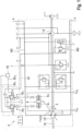
- FIG. 1 is a hydraulic diagram of a drive system for an operating machine with respect to which a regulation method according to an embodiment of the present invention can be used. Only the components which are essential to the invention are described.
- the system has a casing 1 on which two working connections A, B are formed to which a work line (not shown) from a closed circuit is connected, for example one or more hydraulic motors can be connected to the said working connections A, B, respectively.
- a drive system is formed for a mobile work machine (not shown), such as a bulldozer.
- the axial piston pump 12 is made with a slant disk 2 (also referred to, more generally, as an oblique element) whose oscillation angle ⁇ pmp can be set via a regulation unit 4, so as to regulate displacement of the said pump.
- a double-acting regulating cylinder 6 is used which has a first regulating pressure chamber 8 1 and a second regulating pressure chamber 8 2 , which acts in a counter-direction to the first chamber.
- a first regulating pressure p st1 acts in the first regulating pressure chamber 8 1 so as to determine an increase the oscillation angle ⁇ pmp and therefore to determine an increase in the displacement of the pump 12.
- a second regulating pressure p st2 in the second chamber 8 2 acts so as to determine a reduction in the oscillation angle ⁇ pmp and therefore to determine a reduction in the displacement of the pump 12.
- a difference in regulating pressure can be produced, which results from the difference between the first and the second regulating pressure, and the said difference in regulating pressure, by definition, always acts so to determine an increase in the oscillation angle ⁇ pmp , and therefore the said displacement.
- a drive shaft 10 drives the powertrain of the axial piston pump and likewise a feed pump 14,
- the drive shaft 10 can be driven by a diesel engine (not shown), or alternatively by an electric motor, and rotates with a variable speed. This speed acts together with the regulating pressure difference to determine an increase in the oscillation angle ⁇ pmp .
- connection B in the event of forward movement, connection B must be thought of as a high pressure connection, so the line connected to the working connection B is identified as a high pressure line (HD), while the other line connected to the working connection A is identified as a low pressure line (ND).
- the high pressure (HD) which is also called working pressure, acts so as to determine a reduction in the oscillation angle ⁇ pmp .
- the two regulating pressures are controlled via two pressure reducing valves 18 1 , 18 2 . These have an electric magnet a, b, which is connected, respectively, to the electronic control unit 16 via an electric power line 20 1 , 20 2 , respectively.
- the two pressure reducing valves 18 1 , 18 2 are designed so that the respective regulating pressure p st1 , p st2 is proportional to the respective current intensity (I 1 , I 2 ).
- the two pressure reducing valves 18 1 , 18 2 are fed, at the intake, via a pressure supply line 22 from the feed pump 14.
- a test is performed to establish the status of the drive system. Therefore, in this step the pressure downstream p A and upstream p D of pump 12 are inputted. Furthermore, the signal S detects whether the drive system is in a stopped condition.
- a second step 101 the signal inputted by a user of the operating machine on which the said hydrostatic drive system is positioned is detected.
- the signal from the user can be provided thereby via any input unit.
- this input unit may be a joystick, an acceleration pedal, or any lever fitted inside the cab of the operating machine.
- the said signal will simply be referred to as a 'request via pedal' or with synonyms thereof.
- the said signal is preferably received in the form of a relative value.
- the said signal value may be equal to the detected value divided by a reference value.
- the maximum value that can be assumed by the said signal could be chosen as the reference value.
- a percentage value will preferably be used, which will show the user's request with reference to a maximum request that the user could have provided. For example, a 20% pedal signal will mean that the user has requested 20% of the maximum acceleration that they could have requested.
- a ramp is applied, so as to slow down any sudden change in the said request. Therefore, in the event that the user makes a sudden acceleration via the input unit, the said ramp will dampen the input signal, thereby preventing jerking.
- a multiplication factor ⁇ d can be calculated, whose use will become clearer over the course of the present description.
- the said multiplication factor ⁇ d has a constant value until the request via pedal reaches a threshold value. For values above the said threshold value, the said multiplication factor ⁇ d decreases as the request increases.
- step 100 there are two types of drive system control depending on whether a stopped or drive condition has been detected in step 100 or a slowdown condition has been detected. If a stopped or drive condition has been detected, the method proceeds with step 103, while if a slowdown condition has been detected, the method proceeds with step 104.
- step 103 the following are received as input: the multiplication factor ⁇ d calculated in step 102 as described above, a desired speed n D of the drive motor, preferably detected based on the request via pedal, and an actual speed of the said drive motor n Act (or a value dependent thereupon).
- n EngG f d ⁇ n D + 1 ⁇ f d ⁇ n Act
- n EngG corresponds to the said control speed
- f d to the said multiplication factor
- n D to the said desired speed
- n Act to the said actual speed. Therefore, in the event that the request via pedal is low, the control speed is the same as the desired speed as the multiplication factor is one. However, in the event that the request via pedal is particularly high and the multiplication factor is zero, the control speed is the same as the actual speed of the drive motor. In intermediate cases, however, the control speed takes into consideration both values, i.e. the actual speed and the desired speed. The advantages thereof will become clearer in the description referring to Figures 3 to 7 , which show the value assumed by the control speed in different situations.
- the formula described above can be replaced by different formulas and therefore the present invention is not limited to the said embodiment, which has been described purely for illustrative purposes.
- the multiplication factor f d can also be calculated differently.
- the function used in step 102 to calculate the multiplication factor can be, for example, completely the opposite, i.e. envisaging that the said multiplication factor is zero for low request via pedal values and one for high values. In the said case, however, the function used to calculate the control speed will be complementary to that described in Figure 2 .
- control speed assumes the actual speed of the drive motor as its value so as to guarantee load-dependent performance during the slowdown stage.
- step 100 in the event that a change in the condition is detected in step 100, a different logic will be used to determine the control speed and therefore to control the hydraulic pump.
- the method can comprise the following step:
- the method can comprise the following steps:
- the said correction based on the said calculated difference is achieved by applying a correction factor to the said control speed, the said correction factor being proportional to the said difference and inversely proportional to the time passed since the said change from the said stopped or drive condition to the said slowdown condition, with the result that the said correction will be less noticeable and guarantee a smooth transition between the two conditions.
- Figure 3 shows the performance of the drive system in a condition in which, from a stopped condition, the speed requested via the pedal accelerates sharply, from 0 to 100 in a short time, and subsequently remains constant at 100.
- the control speed shown with the solid line follows the same trend as the desired speed. However, if the said ramp were not present it would be clear, based on the logic shown in
- Figure 4 shows a deceleration condition in which, as can be seen from the logic shown in Figure 2 , the hydraulic pump is regulated based on the actual speed of the drive motor, therefore with a smooth and load-dependent performance.
- Figure 5 shows a fine positioning condition in which the acceleration pedal, as shown in the upper part of the figure, is pressed gradually until it reaches 50%.
- the pump is controlled according to the desired speed, given that the multiplication factor assumes a value of either 1 or not significantly different from 1.
- the said fine control is direct, without any delays or instability in the motor speed, therefore without causing sudden stops that would instead occur if the EDA system were used and there were suddenly an increase in load (due to external conditions).
- step 104 the control envisaged in step 104 would then begin, i.e. pump control based on the actual speed of the drive motor. All the foregoing happens continuously, limiting the transition gradient, thanks to the precaution described above regarding this particular case.
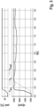
- Figure 6 shows a fine positioning condition in which the acceleration pedal, as shown in the upper part of the figure, is pressed and released sharply (compared to the example in Figure 5 ).
- the figure shows two different examples which correspond to an acceleration and a release of the pedal of around 0-30% (between 15 and 18s) and an acceleration and a release of the pedal of around 0-50% (between 19 and 22s).
- the control speed is an intermediate value between the actual speed and the desired speed.
- the control speed assumes the same value as the desired speed.
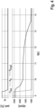
- FIG 7 shows an example of slow driving (the accelerator is pressed just slightly) with the simultaneous use of tools (such as an excavator shovel).
- tools such as an excavator shovel.
- a load is added to the motor, such as when lifting a weight.
- a control based purely on the desired speed is shown (i.e. what happens thanks to the control shown in Figure 2 , i.e. a low pedal request and therefore a multiplication factor of 1).
- variations in the drive motor speed directly affect the pump control flow, guaranteeing the operating machine on which the drive system is positioned a constant speed.
- the present invention further describes a computational unit adapted to perform a method according to any of the previous claims.
- the present description comprises a computer program that causes a computational unit to perform a method such as that described in the present invention.
Landscapes
- Engineering & Computer Science (AREA)
- General Engineering & Computer Science (AREA)
- Mechanical Engineering (AREA)
- Operation Control Of Excavators (AREA)
- Fluid-Pressure Circuits (AREA)
Applications Claiming Priority (1)
| Application Number | Priority Date | Filing Date | Title |
|---|---|---|---|
| IT102023000002460A IT202300002460A1 (it) | 2023-02-14 | 2023-02-14 | Metodo di regolazione di un sistema di trazione idrostatico |
Publications (1)
| Publication Number | Publication Date |
|---|---|
| EP4417841A1 true EP4417841A1 (de) | 2024-08-21 |
Family
ID=86100152
Family Applications (1)
| Application Number | Title | Priority Date | Filing Date |
|---|---|---|---|
| EP24155943.4A Pending EP4417841A1 (de) | 2023-02-14 | 2024-02-06 | Verfahren zur regelung eines hydrostatischen fahrsystems |
Country Status (2)
| Country | Link |
|---|---|
| EP (1) | EP4417841A1 (de) |
| IT (1) | IT202300002460A1 (de) |
Citations (2)
| Publication number | Priority date | Publication date | Assignee | Title |
|---|---|---|---|---|
| US20030010025A1 (en) * | 2001-07-13 | 2003-01-16 | Deere & Company | Anti-stall transmission control for utility vehicle |
| US20170241448A1 (en) * | 2016-02-18 | 2017-08-24 | Takeuchi Mfg. Co., Ltd. | Control device for hydraulic traveling device |
-
2023
- 2023-02-14 IT IT102023000002460A patent/IT202300002460A1/it unknown
-
2024
- 2024-02-06 EP EP24155943.4A patent/EP4417841A1/de active Pending
Patent Citations (2)
| Publication number | Priority date | Publication date | Assignee | Title |
|---|---|---|---|---|
| US20030010025A1 (en) * | 2001-07-13 | 2003-01-16 | Deere & Company | Anti-stall transmission control for utility vehicle |
| US20170241448A1 (en) * | 2016-02-18 | 2017-08-24 | Takeuchi Mfg. Co., Ltd. | Control device for hydraulic traveling device |
Also Published As
| Publication number | Publication date |
|---|---|
| IT202300002460A1 (it) | 2024-08-14 |
Similar Documents
| Publication | Publication Date | Title |
|---|---|---|
| US5576962A (en) | Control system and method for a hydrostatic drive system | |
| US11035462B2 (en) | Work vehicle and control method for work vehicle | |
| US7841442B2 (en) | Hydrostatic transmission | |
| US5873427A (en) | Method and apparatus for controlling a load of an engine associated with a hydrostatic drive system | |
| EP0513382A1 (de) | Stufenloses getriebe für fahrzeug | |
| JP2008144969A (ja) | トランスミッションの動作方法 | |
| EP0301896B1 (de) | Hydraulische Kontrollvorrichtung für ein Kraftfahrzeug mit stufenlos variabler Kraftübertragung | |
| JP2001108098A (ja) | 油圧機械式駆動装置用の下限速度制御装置及びその作動方法 | |
| CN102959285B (zh) | 作业车辆及作业车辆的控制方法 | |
| CN110657235B (zh) | 用于静压传动装置的轮子驱动布置结构和静压传动装置 | |
| JP5727035B2 (ja) | 自動変速機の制御装置 | |
| CN104093957B (zh) | 用于控制发动机转矩载荷的系统和方法 | |
| EP4417841A1 (de) | Verfahren zur regelung eines hydrostatischen fahrsystems | |
| US12071138B2 (en) | Work machine and method for controlling work machine | |
| JP2968558B2 (ja) | トルクコンバータ付き走行作業車両の油圧ポンプ制御装置 | |
| CN113187689B (zh) | 一种液压泵排量控制方法、装置、电子设备和存储介质 | |
| CN103988001B (zh) | 控制无级变速器中的传动比变化率的方法 | |
| US20200141488A1 (en) | Control device for continuously variable transmission and control method for continuously variable transmission | |
| CN101498368B (zh) | 液压无级变速器的控制方法 | |
| EP2370299B1 (de) | Verfahren zum zurückführen einer drehmomentregulierung aus einem begrenzten zustand in einen unbegrenzten zustand | |
| EP4080032A1 (de) | Stufenloses hydrostatisches getriebesystem | |
| CN115667714B (zh) | 用于适配行驶驱动装置的液压泵的压力的方法 | |
| JP2001304389A (ja) | ベルト式無段変速機の変速制御装置 | |
| CN114909452B (zh) | 静液压恒速驱动系统 | |
| JP2000081004A (ja) | 油圧機械的駆動システム用アンダ―スピ―ド制御システム及びその操作方法 |
Legal Events
| Date | Code | Title | Description |
|---|---|---|---|
| PUAI | Public reference made under article 153(3) epc to a published international application that has entered the european phase |
Free format text: ORIGINAL CODE: 0009012 |
|
| STAA | Information on the status of an ep patent application or granted ep patent |
Free format text: STATUS: THE APPLICATION HAS BEEN PUBLISHED |
|
| AK | Designated contracting states |
Kind code of ref document: A1 Designated state(s): AL AT BE BG CH CY CZ DE DK EE ES FI FR GB GR HR HU IE IS IT LI LT LU LV MC ME MK MT NL NO PL PT RO RS SE SI SK SM TR |
|
| STAA | Information on the status of an ep patent application or granted ep patent |
Free format text: STATUS: REQUEST FOR EXAMINATION WAS MADE |
|
| 17P | Request for examination filed |
Effective date: 20250221 |
|
| STAA | Information on the status of an ep patent application or granted ep patent |
Free format text: STATUS: EXAMINATION IS IN PROGRESS |
|
| 17Q | First examination report despatched |
Effective date: 20260126 |