EP4417543A1 - Zusammenklappbare hinter-kabine-einrichtung zum heben und behandeln von abfallsammelcontainern - Google Patents
Zusammenklappbare hinter-kabine-einrichtung zum heben und behandeln von abfallsammelcontainern Download PDFInfo
- Publication number
- EP4417543A1 EP4417543A1 EP24158563.7A EP24158563A EP4417543A1 EP 4417543 A1 EP4417543 A1 EP 4417543A1 EP 24158563 A EP24158563 A EP 24158563A EP 4417543 A1 EP4417543 A1 EP 4417543A1
- Authority
- EP
- European Patent Office
- Prior art keywords
- arm
- axis
- container
- rotation
- crosspiece
- Prior art date
- Legal status (The legal status is an assumption and is not a legal conclusion. Google has not performed a legal analysis and makes no representation as to the accuracy of the status listed.)
- Pending
Links
- 239000002699 waste material Substances 0.000 title claims abstract description 28
- 230000008878 coupling Effects 0.000 claims description 20
- 238000010168 coupling process Methods 0.000 claims description 20
- 238000005859 coupling reaction Methods 0.000 claims description 20
- 238000005265 energy consumption Methods 0.000 claims description 9
- 238000000034 method Methods 0.000 claims description 6
- 230000008569 process Effects 0.000 claims description 5
- 238000013519 translation Methods 0.000 claims description 3
- 238000012937 correction Methods 0.000 description 9
- 230000008901 benefit Effects 0.000 description 6
- 238000005259 measurement Methods 0.000 description 6
- 230000009467 reduction Effects 0.000 description 5
- 235000001674 Agaricus brunnescens Nutrition 0.000 description 4
- 238000004519 manufacturing process Methods 0.000 description 3
- 230000002411 adverse Effects 0.000 description 2
- 229910052799 carbon Inorganic materials 0.000 description 2
- 238000010276 construction Methods 0.000 description 2
- 238000001514 detection method Methods 0.000 description 2
- 230000000694 effects Effects 0.000 description 2
- 238000012423 maintenance Methods 0.000 description 2
- 239000000463 material Substances 0.000 description 2
- 230000036961 partial effect Effects 0.000 description 2
- OKTJSMMVPCPJKN-UHFFFAOYSA-N Carbon Chemical compound [C] OKTJSMMVPCPJKN-UHFFFAOYSA-N 0.000 description 1
- 230000002159 abnormal effect Effects 0.000 description 1
- 230000009471 action Effects 0.000 description 1
- 230000008859 change Effects 0.000 description 1
- 238000002485 combustion reaction Methods 0.000 description 1
- 230000002860 competitive effect Effects 0.000 description 1
- 230000001419 dependent effect Effects 0.000 description 1
- 239000003344 environmental pollutant Substances 0.000 description 1
- 230000005484 gravity Effects 0.000 description 1
- 230000010355 oscillation Effects 0.000 description 1
- 231100000719 pollutant Toxicity 0.000 description 1
- 239000003381 stabilizer Substances 0.000 description 1
- XLYOFNOQVPJJNP-UHFFFAOYSA-N water Substances O XLYOFNOQVPJJNP-UHFFFAOYSA-N 0.000 description 1
Images


Classifications
-
- B—PERFORMING OPERATIONS; TRANSPORTING
- B65—CONVEYING; PACKING; STORING; HANDLING THIN OR FILAMENTARY MATERIAL
- B65F—GATHERING OR REMOVAL OF DOMESTIC OR LIKE REFUSE
- B65F3/00—Vehicles particularly adapted for collecting refuse
- B65F3/02—Vehicles particularly adapted for collecting refuse with means for discharging refuse receptacles thereinto
- B65F3/0203—Vehicles particularly adapted for collecting refuse with means for discharging refuse receptacles thereinto with crane-like mechanisms
-
- B—PERFORMING OPERATIONS; TRANSPORTING
- B65—CONVEYING; PACKING; STORING; HANDLING THIN OR FILAMENTARY MATERIAL
- B65F—GATHERING OR REMOVAL OF DOMESTIC OR LIKE REFUSE
- B65F3/00—Vehicles particularly adapted for collecting refuse
- B65F3/02—Vehicles particularly adapted for collecting refuse with means for discharging refuse receptacles thereinto
- B65F2003/0263—Constructional features relating to discharging means
- B65F2003/0266—Constructional features relating to discharging means comprising at least one telescopic arm
-
- B—PERFORMING OPERATIONS; TRANSPORTING
- B65—CONVEYING; PACKING; STORING; HANDLING THIN OR FILAMENTARY MATERIAL
- B65F—GATHERING OR REMOVAL OF DOMESTIC OR LIKE REFUSE
- B65F3/00—Vehicles particularly adapted for collecting refuse
- B65F3/02—Vehicles particularly adapted for collecting refuse with means for discharging refuse receptacles thereinto
- B65F2003/0263—Constructional features relating to discharging means
- B65F2003/0273—Constructional features relating to discharging means capable of rotating around a vertical axis
Definitions
- This invention relates to a foldable rear-cabin apparatus for lifting and moving waste collection containers, and to a machine on which the apparatus is mounted.
- this apparatus does not allow any correction of misalignment between the vertical axis of the crane and the vertical axis of the container. Any misalignments are only compensated for by the clearances and tolerances allowed by the gripping unit with all the mechanical stresses and operational limitations that this constructional solution entails.
- Patent document EP2614017 B1 shows another embodiment of a crane with a telescopic vertical column, where, in order to increase the operating area and allow the gripping and emptying also of underground containers without the application of auxiliary devices (cranes with the extensible arm, also called "JIB crane"); the vertical telescopic column has a significant extension in height, greater than the solution described above.
- the telescopic column is mounted on a rotary platform (rack) located at the base of the column.
- the top of this telescopic vertical element is hinged, with a suitable support, to a second telescopic element where, at the outer end, the device for gripping the containers is anchored.
- This first telescopic arm having a point of rotation at a height greater than the height of the skip and of the cabin of the truck increases the operating area of the apparatus allowing the movement also of two adjacent containers located laterally to the vehicle.
- Patent document EP 2821360 B1 shows another embodiment of a telescopic apparatus which moves on Cartesian axes where, in order to improve the positioning of the crane relative to the container and allow the movement of underground containers without the aid of jib cranes, the two vertical and horizontal telescopic elements, characteristic of the crane described in patent document EP1084069 , have been added with, at the end of the horizontal telescopic arm, a third vertical telescopic element for gripping containers as well as having inserted in the central column, in place of the jib crane, another two telescopic elements, necessary to reach a greater height, which is essential for moving and emptying the underground containers inside the skip since said containers are characterised by a height of almost 3.4 m, which is twice the height of the containers positioned above the ground which have a height of approximately 1.7 m.
- the support of the horizontal telescopic element and of the third vertical telescopic element, to which the gripping unit is anchored are equipped with an joint which allows a partial rotation on the respective axes to perform the correction of the position of the axis of the gripping unit relative to the perpendicular to the ground.
- An automatic device for correcting the inclination repositions the axis of the gripping unit perpendicular to the ground also in the case of positioning the vehicle outside the plane.
- the correction crane does not take into account the need to correct the inclination of the gripping unit in relation to the actual position and inclination of the container.
- correction is essential when using rigid type lifting couplings such as the F90 hooking system or the double mushroom system.
- the out-of-plane positioning of the container is a typical condition and very frequent when it is not positioned on a specific pad.
- the inclination is caused by the normal slope of the roadbed formed for the runoff of water, a slope which, in the outer zone of the road, is generally greater than the central zone of the carriageway.
- the differences of inclination between the vehicle positioned on the carriageway and the container positioned outside the carriageway cannot be managed with the system indicated in patent document EP 2821360 B1 nor with the other apparatuses mentioned above.
- these apparatuses are forced to operate on a limited operating area, forcing the vehicle to occupy a specific position to be able to pick up the skip.
- the aim of the invention is to overcome the above-mentioned drawbacks of prior art types of foldable rear-cabin apparatus for lifting and moving waste collection containers which allows a skip to be picked up easily and quickly in any situation with the pick-up zone, irrespective of the traffic, how the parked cars are parked and the dimensions of the road.
- another aim of the invention is to improve the functionality of the foldable rear-cabin apparatus for lifting and moving containers for collecting waste, as well as their operational and constructional simplicity.
- Another aim of the apparatus according to the invention is to reduce the cycle times and limit the maintenance costs and the energy consumption necessary for operation of the apparatus.
- this invention relates to a foldable rear-cabin apparatus for lifting and moving stationary containers for waste collection, which comprises a column element which extends perpendicularly to a base, which is designed to be associated with a vehicle.
- the column element is fixed on the base. According to a variant, it can rotate about its axis of symmetry by means of a rotatable support. This axis of symmetry is substantially normal relative to the ground.
- the column element is rotatably connected to a crosspiece which extends in a direction substantially normal relative to the axis of symmetry. If the column element can rotate, the crosspiece will be integral in rotation with the column element.
- a first arm is mounted on the crosspiece in such a way that it can rotate about a first axis of rotation by means of a first joint; the first joint is positioned at the vertex of a first angle drawn by the rotation of the first arm relative to the crosspiece.
- the apparatus also comprises a second arm, preferably telescopic, which pivots at the end of the first arm, about a second axis of rotation by means of a second joint positioned at the vertex of a second angle drawn by the mutual rotation of the first and of the second arm.
- the second arm also has, at the end opposite the second joint, a gripping unit for the stationary containers.
- the first arm is configured to be rotated about the first axis by means of a first actuator, transporting with it the second arm in a rotary movement; the second arm, for its part, is designed to rotate also about the second axis by means of a second actuator.
- the gripping unit is adjustable and may be aligned on the basis of the position of the container.
- the crosspiece is designed to perform an entire revolution about the relative axis of symmetry, in such a way as to also be able to pick up the skips positioned in front of the vehicle on which the apparatus is mounted, in the case, for example, of narrow roads or with obstacles (parked cars, trees, gazebos, etc.) which would otherwise limit the operation.
- the rotations of the first and of the second arm about the relative axes occur between an initial position and a succession of operating positions.
- the crosspiece and the first arm are substantially aligned whilst the first and the second arm are substantially perpendicular to each other; in the operating positions the crosspiece and the first arm are not substantially aligned with each other and/or the first and the second arm are not substantially perpendicular to each other.
- the Applicant understood that by projecting the crosspiece from the axis of symmetry by a length such that, in the rest configuration, that is to say, when the crane is folded in the rear-cabin, the distance between the second axis and the axis of symmetry is less than or equal to the distance between the first axis and the axis of symmetry, a larger operating surface is reached.
- This increased operating area achieved with the specific articulation of the arms and positioning of the centres of rotation, allows the apparatus to lift and move containers positioned above the ground or underground without requiring the movement of the vehicle to perform an accurate centring of several containers located in the operating area, with all the advantages in terms of operating times and energy consumption.
- sensors have been provided for detecting the real position and inclination of the container relative to the position and inclination of the column element, in such a way as to detect the position and the inclination of the container relative to the position of the apparatus.
- the sensors are also for controlling the positioning of the gripping unit at the point calculated for coupling the container: the electronic control system of the apparatus acquires the specific data of the position and inclination of the container and, after detecting the real position and inclination of the apparatus with specific inclinometers and angular and position sensors, it manages and controls the necessary movements of the crane arms and of the gripping unit for positioning said gripping unit at the point required for coupling the container.
- another aspect of the invention relates to the use of an electronic control system, with reading of the position and inclination of the container, by means of systems for three-dimensional measurement and systems for measuring the inclination of the column element and of the gripping unit.
- This thanks to inclination sensors which allow the inclination of the gripping unit to be corrected, on the basis of the telemetric information processed by the electronic command and control system, allowing the central axis of the gripping unit to be positioned in such a way that it is coaxial with the axis of extension of the container.
- the protection is also required for a machine for lifting and moving stationary containers for waste collection, which comprises, on a vehicle provided with a waste collection skip (and advantageously the relative unloading hopper), a crane according to this invention.
- Another aspect of the invention relates to a process for gripping and moving a stationary waste collection container using the foldable rear-cabin apparatus for lifting and moving stationary waste collection containers described here.
- the process comprises rotatably actuating the crosspiece, modifying the first angle, defined between the crosspiece and the first arm, using the first actuator means, modifying the second angle, defined between the first and the second arm using second actuator means, detecting the real position and inclination of the axis of extension of the container relative to the real position and inclination of the axis of symmetry, by means of the sensors, and therefore positioning the central axis of symmetry of the gripping unit, in such a way that it coincides with the axis of the container, in order to guarantee a perfect coupling of the container.
- the first arm is rotated in such a way as to lift the container and, at the same time, withdraw the container towards the column element to allow the roto-translation of the second arm. Therefore, during unloading, the container is positioned in an area of the hopper adjacent to the column of the apparatus, in such a way as to avoid interference between the container and the second arm. In this way, the increase in the volume of the waste collection skip not occupied by the unloading hopper is allowed.
- the first arm In order to reduce the lifting forces necessary to move the container, the first arm is rotated about the first axis, consequently moving the centres of mass of the first and of the second arms relative to the axis of symmetry. In effect, in this way, the centres of mass are moved between the step of gripping the container and the step of emptying.
- the rotation of the first arm determines the vertical movement of the centre of rotation of the second axis, allowing an increase in the operating area of the apparatus, in such a way that it can also operate in the front part of the vehicle for lifting containers positioned in the operating area without moving the vehicle.
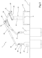
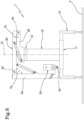
- FIG. 1 shows a preferred embodiment of a foldable rear-cabin apparatus for lifting and moving waste collection containers, according to the invention, which is identified in its entirety with the numeral 1 and which comprises a column element 10, vertical relative to the ground T, fixed to a fixed base 11 complete with stabilisers 12 suitable for mounting on a truck 200 or any other suitable vehicle.
- a rotatable support 13 for example a rack, where a crosspiece 20 is anchored.
- the crosspiece 20 rotates about the axis of symmetry A1 of the element 10 by means of a gear motor, not illustrated, and thanks to the rotatable support 13.
- the axis of symmetry A1 is therefore substantially normal relative to the ground T.
- the rotatable support 13 may be installed in the lower part of the column 10 which at that point will be rotatable and integrally connected to the crosspiece 20.
- the crosspiece 20 has a length comprised in the width of the bodywork of the truck 200 or less; it is positioned at a height greater than the height of the cabin 207 of the truck 200 and of the unloading hopper 202, in such a way as to allow a free rotation without interference with said elements.
- the height of rotation of the crosspiece 20 is obtained with a specific length of the column element 10.
- the length of the column element 10 in the solution described here is purposely, but not necessarily, made with a single component without any telescopic or other movement, in such a way as to reduce the weights and the production costs.
- variants may comprise the possibility of telescopically modifying the height of the element 10.
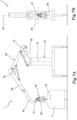
- a second arm 40 in this case telescopic, is fixed to the end of the first arm 30 by a second joint 31.
- the joint 31 defines a first axis A2 of rotation, obviously allowing the rotation of the second arm 40 about the axis A2 so as to allow the variation of the second angle O2 defined between said two arms 30 and 40.
- the other end of the telescopic arm 40, opposite the joint 31, is connected to a gripping unit 50, anchored by a first pin 41.
- the gripping unit 50 allows a container C to be coupled to the end of the second arm 40 for its lifting.
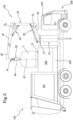
- the apparatus 1 is mounted on a vehicle 200 to form a machine 100 ( Figures 3-5 ) for lifting and moving stationary containers for waste collection, which comprises the vehicle 200 equipped with a waste collection skip 201 and the respective unloading hopper 202, and the apparatus 1 according to the invention.
- the point of rotation of the arm 30 moves through the crosspiece 20, which has a length within the width of the truck 200, allowing all the geometries of movement of the apparatuses shown to be made.
- the crosspiece 20 projects from the axis of symmetry A1 by a length such that, in the rest configuration, the distance between the second axis A3 and the axis of symmetry A1 is less than or equal to the distance between the first axis A2 and the axis of symmetry A1.
- the crosspiece 20 projects from the axis of symmetry A1 of the column element 10 by a length at least equal to the diameter of the column element 10.
- the distance between the axis of symmetry A1 and the first axis A2 is equal to the distance between the axis of symmetry A1 and the second axis A3, so as to have maximum compactness at rest and excellent possibility of manoeuvring the gripping unit 50.
- First actuation means hydraulic, electrical or other type 22, which may consist of one or more actuators, allows the arm 30 to be rotated relative to the first axis of rotation A2 of the pin 21 varying the angle between the element 20 and 30.
- Second actuation means hydraulic, electrical or other type of 32, which may consist of one or more actuators, allows the arm 40 to be rotated relative to the second axis A3 of the pin 31 varying the angle between the arms 30 and 40.
- the rotation around the axes A2 and A3 may also be performed with rotary actuators or other actuation systems.
- the rotation of the gripping unit 50 is performed by a hydraulic, electrical or other type of actuator, inserted in the arm of the sliding member 42 of the second arm 40.
- the telescopic arm 40 may have one or more telescopic sliding members which allow the operating area of the apparatus to be varied.
- the lifting capacity of the apparatus 1 may also vary in relation to the type and weight of the containers to be moved.
- a model of crane 1 with an operating distance for gripping containers of 5000 mm and a lifting capacity of 1600 kg at 5000 mm, or a model of crane with an operating distance greater than, for example, 7500 mm with a lifting capacity of 2000 kg, or different.
- the characteristics of the gripping unit 50 vary, which may have and require specific shapes and movements.
- the gripping unit 50 is suitable for moving containers C with rigid mushroom-shaped coupling.
- the movements indicated guarantee a perfect centring and coupling of the container C, avoiding forces in the gripping of the container C which may adversely affect and cause damage to the gripping unit 50 or the lifting device of the container C, also adversely affecting safety.
- the gripping unit 50 is completed by a further joint inserted in the support 51 which makes it possible to correct the inclination, by means of a specific actuator (not shown), with a rotation of the gripping unit 50 on the axis of rotation A5, perpendicular with respect to the third axis A4 and a rotatable support 53, provided with a relative actuator (not shown) which makes it possible to rotate the container C with respect to the central axis A6.
- the rotatable support 53 allows the container C to be positioned correctly inside the unloading hopper 202 of the skip 201 so as to avoid possible interference of the closing lids C1 of the container C with the walls of the unloading hopper 202.
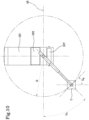
- the rotatable support 53 in the step of coupling the container, allows the gripping unit 50 to be oriented in the correct position required by the coupling devices of the container C ( Figure 10 ), whilst in the step for repositioning on the ground, if necessary, it allows the container to be rotated to change or correct the orientation or the positioning.
- detection sensors such as three-dimensional video cameras 221 or other means of per se known type (inclination 222 and angular 223 sensors), for detecting the real position and inclination (angle O5) of the container C with the axis of extension A7 relative to the position and inclination of the column element 10 relative to the ground T and for detecting the position of the container relative to the transversal axis A8 of the apparatus ( Figure 9 and Figure 10 ).
- the inclination of the column element 10 (with measurement of the angle O4 defined between the axis A1 and the ground T) and of the gripping unit 50 (with measurement of the angle O3 between the axis A6 and the perpendicular to the ground T) is detected by specific inclination sensors 222.
- the position of rotation of the rotatable support 13 of the column element 10 (with the measurement of the angle O7) and of the rotatable support of the gripping unit 50 (with the measurement of the angle O6) is detected by specific sensors of the angular position 223.
- the three-dimensional video cameras 221 and the sensors 222 and 223 are connected to an electronic command and control unit (not illustrated). This unit allows the gripping unit 50 to be positioned at the point exactly calculated for coupling the container C, orienting the gripping unit with the same inclination as the container.
- the correction of the inclination of the gripping unit 50 with the rotation on the axes A4 and A5 is performed by means of specific actuators.
- This correction allows the central axis A6 of the gripping unit 50 to be positioned coinciding perfectly with the axis of extension A7 of the container C, once the real position and inclination of the container C has been detected with its axis of extension A7 relative to the real position and inclination of the axis A1 of the machine 100.
- an electronic control system is provided with a reading of the position and inclination of the container C using three-dimensional measuring systems and detection of the inclination both of the column element 10 and of the gripping unit 50, using inclination sensors 222; in such a way as to correct the inclination of the gripping unit 50, on the basis of the telemetric information processed by the electronic command and control system, thus allowing the axis A6 of the gripping unit 50 to be positioned coaxial with the axis A7 of the container C.
- the apparatus 1 can rotate the arms 30 and 40 about the axis of symmetry A1 freely to 360°; this implies that the apparatus 1 has a large operating radius (R) which is no longer limited by the gap between the cabin 207 and the skip 201 ( Figure 10 ).
- the partial rotation of the first arm 30 on the first axis A2 allows the centre of rotation of the telescopic arm 40, which coincides with the second axis A3, to be raised from the rest configuration to an operating position.
- the vertical movement of the centre of rotation corresponding to the axis A3 makes it possible to increase the operating area covered by the second arm 40, eliminating the interference with the cabin 207 or with the skip 201 of the vehicle 200.
- a radius of action which may also extend to the front part of the vehicle 200 as it is no longer limited by the space between the cabin 207 and the skip 201.
- the number of sliding members of the telescopic arm 40 determines the depth of the operating area given by the distance between the axis A1 of the crane column 10 and the central axis A6 of the gripping unit 50.
- the simple rotation of the arm 30 allows the container C to be lifted and moved towards the vehicle 200.
- This movement thanks to the movement of the masses, the geometrical reduction of the reach and the increase in the lever of the actuator of the crosspiece 20 relative to the first axis of rotation A2 of the arm 30 reduces the force necessary for lifting and the relative energy consumption.
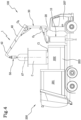
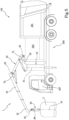
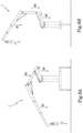
- Figures 3 and 4 show the unloading of the container C, respectively, of the type above ground and underground, in a skip 201 provided with an unloading hopper 202, positioned in the front part of the skip 201, and of the press 203. Thanks to the vertical rotation of the arm 30 performed with the actuator 22, the telescopic arm 40 is also rotated with consequent lifting and translation of the container C towards the hopper 202. This articulation of the arms makes it possible to not have interferences, both for the containers above ground and for the underground containers, between the lifting arm 40 and the container C both during lifting and unloading.
- the centre of rotation A3 is withdrawn, towards the front part of the vehicle 200.
- This withdrawal allows the unloading of the containers C in the front part of the hopper 202 without having interferences between the container C and the arm 40 and allows the depth of the unloading hopper 202 to be limited, with obvious advantages in terms of the volume of the skip 201 not occupied by a hopper with larger dimensions required for all those apparatuses which do not have this feature.
- the geometries of the apparatus 1 allow operation to be easily performed also for unloading in containers C open at the top, without the hopper 202.
- the invention achieves the preset purpose and aims and in particular the fact that a foldable rear-cabin apparatus is made for lifting and moving waste collection containers which allows a skip to be gripped quickly and easily lifted in any situation of the picking up zone.
- the gripping unit may be positioned in such a way that the actual inclination and position of the machine, that is to say, of the vehicle and of the apparatus, are perfectly coaxial relative to the inclination and to the position of the container.
- This correction is essential to ensure an optimum coupling and a safe lifting of all the containers provided with a rigid lifting hook such as, for example, all the containers with a mushroom lifting hook.
- Another advantage of the invention is that it improves the functionality of the foldable rear -cabin apparatus for lifting and moving containers for collecting waste, as well as their operating and production simplicity, thanks to the particular geometry of the foldable apparatus which, with the specific articulation of the arms and the respective centres of rotation, allows a reduction in the movements necessary for gripping and emptying the container, consequently reducing the cycle times and the energy consumption compared with prior art devices.
- Another advantage of the apparatus according to the invention is to allow a perfect coupling of the container in all the operating conditions, increasing the operating area and also reducing the movements necessary for gripping and emptying the container, with advantages in terms of operating speed and energy consumption.
- the materials used, as well as the dimensions may be of any type, depending on requirements, provided that they are consistent with their production purposes.
Landscapes
- Engineering & Computer Science (AREA)
- Mechanical Engineering (AREA)
- Loading Or Unloading Of Vehicles (AREA)
Applications Claiming Priority (1)
| Application Number | Priority Date | Filing Date | Title |
|---|---|---|---|
| IT202300002796 | 2023-02-20 |
Publications (1)
| Publication Number | Publication Date |
|---|---|
| EP4417543A1 true EP4417543A1 (de) | 2024-08-21 |
Family
ID=87418681
Family Applications (1)
| Application Number | Title | Priority Date | Filing Date |
|---|---|---|---|
| EP24158563.7A Pending EP4417543A1 (de) | 2023-02-20 | 2024-02-20 | Zusammenklappbare hinter-kabine-einrichtung zum heben und behandeln von abfallsammelcontainern |
Country Status (1)
| Country | Link |
|---|---|
| EP (1) | EP4417543A1 (de) |
Citations (6)
| Publication number | Priority date | Publication date | Assignee | Title |
|---|---|---|---|---|
| WO1996017750A1 (fr) | 1994-12-05 | 1996-06-13 | Joseph Daumer | Materiel de levage et de manutention de charges diverses, associe a un vehicule |
| EP1084069A1 (de) | 1998-04-22 | 2001-03-21 | Nord Engineering di Armando Lodovico & C.S.N.C. | Vorrichtung zur handhabung von müllsammelbehältern |
| FR2964648A1 (fr) | 2010-09-14 | 2012-03-16 | Mondini Engineering Sa | Procede et dispositif pour soulever des containers a dechets et pour vider leur contenu |
| EP2821360B1 (de) | 2013-07-03 | 2016-01-20 | Palvi, S.L. | Kran aus teleskopischen Segmenten und Steuerungsverfahren dafür |
| EP2614017B1 (de) | 2010-09-07 | 2016-10-05 | Villiger Public-Systems GmbH | Hebevorrichtung auf einem lastkraftfahrzeug |
| KR20220068500A (ko) | 2020-11-19 | 2022-05-26 | 주식회사 탭스인터내셔널 | 의료폐기물 쓰레기통용 자율이송 카트 |
-
2024
- 2024-02-20 EP EP24158563.7A patent/EP4417543A1/de active Pending
Patent Citations (6)
| Publication number | Priority date | Publication date | Assignee | Title |
|---|---|---|---|---|
| WO1996017750A1 (fr) | 1994-12-05 | 1996-06-13 | Joseph Daumer | Materiel de levage et de manutention de charges diverses, associe a un vehicule |
| EP1084069A1 (de) | 1998-04-22 | 2001-03-21 | Nord Engineering di Armando Lodovico & C.S.N.C. | Vorrichtung zur handhabung von müllsammelbehältern |
| EP2614017B1 (de) | 2010-09-07 | 2016-10-05 | Villiger Public-Systems GmbH | Hebevorrichtung auf einem lastkraftfahrzeug |
| FR2964648A1 (fr) | 2010-09-14 | 2012-03-16 | Mondini Engineering Sa | Procede et dispositif pour soulever des containers a dechets et pour vider leur contenu |
| EP2821360B1 (de) | 2013-07-03 | 2016-01-20 | Palvi, S.L. | Kran aus teleskopischen Segmenten und Steuerungsverfahren dafür |
| KR20220068500A (ko) | 2020-11-19 | 2022-05-26 | 주식회사 탭스인터내셔널 | 의료폐기물 쓰레기통용 자율이송 카트 |
Similar Documents
| Publication | Publication Date | Title |
|---|---|---|
| AU2018315061B2 (en) | A refuse collection device | |
| US20060280582A1 (en) | System for automatically capturing a fully loaded refuse container, and without any spillage, empty the contents of the refuse container into a refuse collection vehicle | |
| CN113800272B (zh) | 港口散改集装卸工艺系统及控制方法 | |
| US20170362030A1 (en) | Articulated front loader arm mechanism for use with a conventional refuse collection extended cab chassis | |
| CN107435289A (zh) | 具有接近导向辅助装置的道路整修机或装料机和接近导向辅助装置 | |
| EP4417543A1 (de) | Zusammenklappbare hinter-kabine-einrichtung zum heben und behandeln von abfallsammelcontainern | |
| CN115571185A (zh) | 一种敞车自动摘钩装置及工作方法 | |
| CN210478656U (zh) | 一种电动环卫车的防倾倒装置 | |
| CN108726381B (zh) | 一种多功能抢险救援车多臂协调作业控制系统 | |
| EP3150513B1 (de) | Fahrzeug mit einer vorrichtung zum sammeln und heben von behältern und entleeren der inhalte davon | |
| CN116727652A (zh) | 一种定位浇注的自动浇注机 | |
| US8857024B2 (en) | Load leveling modification for front loading refuse truck | |
| CN211464811U (zh) | 一种钢包倾翻装置 | |
| CN216764260U (zh) | 臂架移动式配重结构及具有其的高空作业平台 | |
| CN219239095U (zh) | 具有伸展状态检测功能的随车吊伸缩支腿 | |
| US12434954B2 (en) | Lifting attachment for lifting containers | |
| CN115159346B (zh) | 一种智能自动调心翻转吊具及其控制系统、控制方法 | |
| US4378836A (en) | Manipulation method and device for a foundry | |
| EP3862295A1 (de) | Seitliches ladesystem und verfahren zum heben und entleeren eines behälters | |
| CN210505206U (zh) | 放射性废物桶多桶机械吊装设备 | |
| CN113247770B (zh) | 吊具角度调节方法、吊具调节机构及门座起重机 | |
| CN220765897U (zh) | 一种可倾倒矿料的矿车移车机 | |
| CN107601251A (zh) | 一种自动倾倒集装箱吊具 | |
| CA3179093C (en) | Lifting attachment for lifting containers | |
| CN113430324A (zh) | 高废钢比条件下的角度自适应吹气赶渣系统及赶渣方法 |
Legal Events
| Date | Code | Title | Description |
|---|---|---|---|
| PUAI | Public reference made under article 153(3) epc to a published international application that has entered the european phase |
Free format text: ORIGINAL CODE: 0009012 |
|
| STAA | Information on the status of an ep patent application or granted ep patent |
Free format text: STATUS: THE APPLICATION HAS BEEN PUBLISHED |
|
| AK | Designated contracting states |
Kind code of ref document: A1 Designated state(s): AL AT BE BG CH CY CZ DE DK EE ES FI FR GB GR HR HU IE IS IT LI LT LU LV MC ME MK MT NL NO PL PT RO RS SE SI SK SM TR |
|
| STAA | Information on the status of an ep patent application or granted ep patent |
Free format text: STATUS: REQUEST FOR EXAMINATION WAS MADE |
|
| 17P | Request for examination filed |
Effective date: 20250221 |