EP4417394A1 - Inliner für einen extruder - Google Patents
Inliner für einen extruder Download PDFInfo
- Publication number
- EP4417394A1 EP4417394A1 EP23157392.4A EP23157392A EP4417394A1 EP 4417394 A1 EP4417394 A1 EP 4417394A1 EP 23157392 A EP23157392 A EP 23157392A EP 4417394 A1 EP4417394 A1 EP 4417394A1
- Authority
- EP
- European Patent Office
- Prior art keywords
- inliner
- inner part
- extruder
- barrel
- sealing sleeve
- Prior art date
- Legal status (The legal status is an assumption and is not a legal conclusion. Google has not performed a legal analysis and makes no representation as to the accuracy of the status listed.)
- Pending
Links
Images

Classifications
-
- B—PERFORMING OPERATIONS; TRANSPORTING
- B29—WORKING OF PLASTICS; WORKING OF SUBSTANCES IN A PLASTIC STATE IN GENERAL
- B29C—SHAPING OR JOINING OF PLASTICS; SHAPING OF MATERIAL IN A PLASTIC STATE, NOT OTHERWISE PROVIDED FOR; AFTER-TREATMENT OF THE SHAPED PRODUCTS, e.g. REPAIRING
- B29C48/00—Extrusion moulding, i.e. expressing the moulding material through a die or nozzle which imparts the desired form; Apparatus therefor
- B29C48/25—Component parts, details or accessories; Auxiliary operations
- B29C48/256—Exchangeable extruder parts
- B29C48/2565—Barrel parts
-
- B—PERFORMING OPERATIONS; TRANSPORTING
- B29—WORKING OF PLASTICS; WORKING OF SUBSTANCES IN A PLASTIC STATE IN GENERAL
- B29C—SHAPING OR JOINING OF PLASTICS; SHAPING OF MATERIAL IN A PLASTIC STATE, NOT OTHERWISE PROVIDED FOR; AFTER-TREATMENT OF THE SHAPED PRODUCTS, e.g. REPAIRING
- B29C48/00—Extrusion moulding, i.e. expressing the moulding material through a die or nozzle which imparts the desired form; Apparatus therefor
- B29C48/25—Component parts, details or accessories; Auxiliary operations
- B29C48/256—Exchangeable extruder parts
- B29C48/2568—Inserts
- B29C48/25684—Inserts for barrels
-
- B—PERFORMING OPERATIONS; TRANSPORTING
- B29—WORKING OF PLASTICS; WORKING OF SUBSTANCES IN A PLASTIC STATE IN GENERAL
- B29C—SHAPING OR JOINING OF PLASTICS; SHAPING OF MATERIAL IN A PLASTIC STATE, NOT OTHERWISE PROVIDED FOR; AFTER-TREATMENT OF THE SHAPED PRODUCTS, e.g. REPAIRING
- B29C48/00—Extrusion moulding, i.e. expressing the moulding material through a die or nozzle which imparts the desired form; Apparatus therefor
- B29C48/25—Component parts, details or accessories; Auxiliary operations
- B29C48/36—Means for plasticising or homogenising the moulding material or forcing it through the nozzle or die
- B29C48/50—Details of extruders
- B29C48/68—Barrels or cylinders
- B29C48/6801—Barrels or cylinders characterised by the material or their manufacturing process
-
- B—PERFORMING OPERATIONS; TRANSPORTING
- B29—WORKING OF PLASTICS; WORKING OF SUBSTANCES IN A PLASTIC STATE IN GENERAL
- B29C—SHAPING OR JOINING OF PLASTICS; SHAPING OF MATERIAL IN A PLASTIC STATE, NOT OTHERWISE PROVIDED FOR; AFTER-TREATMENT OF THE SHAPED PRODUCTS, e.g. REPAIRING
- B29C48/00—Extrusion moulding, i.e. expressing the moulding material through a die or nozzle which imparts the desired form; Apparatus therefor
- B29C48/25—Component parts, details or accessories; Auxiliary operations
- B29C48/36—Means for plasticising or homogenising the moulding material or forcing it through the nozzle or die
- B29C48/50—Details of extruders
- B29C48/68—Barrels or cylinders
- B29C48/6803—Materials, coating or lining therefor
-
- B—PERFORMING OPERATIONS; TRANSPORTING
- B29—WORKING OF PLASTICS; WORKING OF SUBSTANCES IN A PLASTIC STATE IN GENERAL
- B29C—SHAPING OR JOINING OF PLASTICS; SHAPING OF MATERIAL IN A PLASTIC STATE, NOT OTHERWISE PROVIDED FOR; AFTER-TREATMENT OF THE SHAPED PRODUCTS, e.g. REPAIRING
- B29C48/00—Extrusion moulding, i.e. expressing the moulding material through a die or nozzle which imparts the desired form; Apparatus therefor
- B29C48/25—Component parts, details or accessories; Auxiliary operations
- B29C48/78—Thermal treatment of the extrusion moulding material or of preformed parts or layers, e.g. by heating or cooling
- B29C48/80—Thermal treatment of the extrusion moulding material or of preformed parts or layers, e.g. by heating or cooling at the plasticising zone, e.g. by heating cylinders
- B29C48/82—Cooling
-
- B—PERFORMING OPERATIONS; TRANSPORTING
- B29—WORKING OF PLASTICS; WORKING OF SUBSTANCES IN A PLASTIC STATE IN GENERAL
- B29C—SHAPING OR JOINING OF PLASTICS; SHAPING OF MATERIAL IN A PLASTIC STATE, NOT OTHERWISE PROVIDED FOR; AFTER-TREATMENT OF THE SHAPED PRODUCTS, e.g. REPAIRING
- B29C48/00—Extrusion moulding, i.e. expressing the moulding material through a die or nozzle which imparts the desired form; Apparatus therefor
- B29C48/25—Component parts, details or accessories; Auxiliary operations
- B29C48/78—Thermal treatment of the extrusion moulding material or of preformed parts or layers, e.g. by heating or cooling
- B29C48/80—Thermal treatment of the extrusion moulding material or of preformed parts or layers, e.g. by heating or cooling at the plasticising zone, e.g. by heating cylinders
- B29C48/83—Heating or cooling the cylinders
- B29C48/834—Cooling
-
- B—PERFORMING OPERATIONS; TRANSPORTING
- B29—WORKING OF PLASTICS; WORKING OF SUBSTANCES IN A PLASTIC STATE IN GENERAL
- B29C—SHAPING OR JOINING OF PLASTICS; SHAPING OF MATERIAL IN A PLASTIC STATE, NOT OTHERWISE PROVIDED FOR; AFTER-TREATMENT OF THE SHAPED PRODUCTS, e.g. REPAIRING
- B29C48/00—Extrusion moulding, i.e. expressing the moulding material through a die or nozzle which imparts the desired form; Apparatus therefor
- B29C48/25—Component parts, details or accessories; Auxiliary operations
- B29C48/36—Means for plasticising or homogenising the moulding material or forcing it through the nozzle or die
- B29C48/50—Details of extruders
- B29C48/68—Barrels or cylinders
- B29C48/681—Barrels or cylinders for single screws
Definitions
- the present invention relates to an inliner for an extruder, wherein the inliner is replaceable and has at least one cooling channel.
- Extruders are machines in which materials such as polymers, elastomers or proteinaceous mixtures can be treated under desired pressure and temperature conditions for the production of food products including cereals, snacks, pet food and alternative foods.
- a typical extruder comprises at least one extruder screw shaft, each of the extruder screw shafts having a set of extruder screw elements mounted on the shaft.
- the extruder screw shafts are housed in a cylinder called a barrel.
- An extruder typically comprises several barrels connected end to end. Several barrels are required to carry out the various processes to be performed in the extruder such as conveying, kneading, mixing, degassing, dosing and the like.
- Each barrel includes an insert element known as an inliner, which is pressed into the barrel housing.
- the barrel housing also contains channels for a medium in order to regulate the temperature in the barrel within a desired range.
- the medium guided in the channels can be brought to a desired temperature by temperature control devices such as heat exchangers.
- the inliners comprise a process zone in the form of an axial bore in which at least one extruder screw shaft is arranged and in which the desired treatment of the material to be extruded takes place. Since during the extrusion the If the extruder screw shaft rotates within the process zone and comes into contact with the surface of the inliner process zone, the inliner will wear out over time.
- the inliners In order to ensure a proper extrusion process, the inliners must therefore be replaced after a certain period of time. Since the inliners are usually pressed into the barrel housings, as explained above, replacing an inliner in conventional barrels is a laborious process. The inliner is typically pressed in by shrinking the inliner into the barrel housing, which results in the inliner being so firmly arranged in the barrel housing that when it wears out, the entire system of inliner and barrel housing must be replaced. This is obviously disadvantageous.
- the present invention relates to an inliner for an extruder, comprising an inner part with a process zone leading axially through the inner part, as well as a sealing sleeve completely surrounding the inner part, characterized in that the inner part has at least one cooling channel.
- the inliner according to the invention is constructed in two parts.
- the inliner according to the invention comprises a sealing sleeve and an inner part arranged in the sealing sleeve.
- the sealing sleeve is preferably of an external cylindrical shape and designed in such a way that it can be arranged in a preferably cylindrical through-bore of a barrel of an extruder and can be removed from this again. This can be achieved by the external diameter of the sealing sleeve being slightly (preferably 0.01 to 0.5%) smaller than the diameter of the through-bore of the barrel and thus the sealing sleeve has some "play" in the through-bore of the barrel.
- the sealing sleeve is made of a material that is conventionally used for extruder liners.
- the sealing sleeve is preferably made of a metal or a metal alloy. Examples include iron, steel or alloys that contain aluminum, chromium, molybdenum or combinations of these metals.
- the sealing sleeve completely surrounds the preferably cylindrical inner part of the inventive inliner so that the inner part does not come into contact with the housing of the barrel.
- the sealing sleeve is firmly attached to the inner part.
- the inner part and sealing sleeve cannot be replaced separately from one another, but form an inseparable unit.
- the inner part is also made of a material that is conventionally used for extruder inliners.
- the inner part is preferably made of a metal or a metal alloy. Examples include iron, steel or alloys that contain aluminum, chromium, molybdenum or combinations of these metals.
- connection between the sealing sleeve and the inner part can be made in a conventional manner.
- the sealing sleeve and the inner part are cast parts and the sealing sleeve is shrunk onto the inner part and optionally soldered or welded.
- the inner part comprises a process zone leading axially through the inner part, in the form of a continuous bore in which at least one extruder screw is arranged.
- the process zone is selected from the group consisting of a cylindrical process zone and two partially overlapping cylindrical process zones. This corresponds to the design of a single-screw extruder or a twin-screw extruder.
- the present invention is not limited to these variants, but can also be used in Multi-screw extruders with more than two extruder screws are used.
- the design of the inliner according to the invention makes it possible to arrange at least one cooling channel in the inner part of the inliner according to the invention in a simple manner. Since the inner part is preferably manufactured separately from the sealing sleeve, the at least one cooling channel can be provided in the inner part before the sealing sleeve is applied to the inner part. According to a preferred embodiment, more than one cooling channel, for example 2 to 10 cooling channels, can be provided in the inner part. These cooling channels can be connected to one another or have overlaps. According to the invention, each cooling channel preferably has a diameter in the range of 5 to 20 mm, more preferably 8 to 12 mm.
- the at least one cooling channel is arranged closer to the process zone of the inliner, since, as stated above, it is provided directly in the inner part of the inliner (and not in the barrel housing as in the prior art). This leads to a significant improvement in the temperature control efficiency.
- the at least one cooling channel can be a bore or groove which extends axially through or outside the inner part and is arranged parallel to the process zone.
- the at least one cooling channel is arranged in or on the surface of the inner part.
- the at least one cooling channel is arranged in the form of a cooling spiral in the surface of the inner part.
- the at least one Cooling channel provided as a cooling channel part in the surface of the inner part, particularly preferably as a channel open to the outside.
- the at least one cooling channel part is created during the manufacture of the inner part, for example by casting the inner part in a mold, which creates corresponding cooling channel parts in the surface of the inner part.
- the at least one cooling channel part in the surface of the inner part is then closed to the outside by applying the sealing sleeve to the inner part as described above and forms the complete cooling channel.
- the inliner according to the invention preferably has elements with which inliners according to the invention can be connected to one another at the end.
- positioning holes can be provided, for example, at the two ends of the inner part and/or the sealing sleeve, preferably the inner part, in which fastening elements such as screws or pins can be arranged.
- the inner part of the inliner according to the invention preferably has 2 to 10, particularly preferably 2 to 6, positioning holes on each end.
- the inliner has at least one radial bore which leads through the sealing sleeve and the inner part into the process zone.
- at least one radial through-channel is formed, which can be a material inlet or can be used to arrange a measuring device.
- water or a gas can be introduced into the material to be extruded in the process zone through a passage channel designed in this way, for example to adjust the moisture content of the material to be extruded. material or to create pore formation in the material to be extruded.
- the inliner according to the invention is not particularly limited with regard to the number and position of these radial bores.
- 2 to 10 preferably 3-6 radial bores can be provided parallel or offset from one another.
- the diameter of a radial bore is preferably in the range of 1 mm to 5 cm.
- the inliner according to the invention is arranged in a barrel as described above.
- the present invention therefore also relates to a barrel for an extruder, comprising an outer housing and a through-bore, characterized in that an inliner according to the present invention is arranged in an exchangeable manner in the through-bore.
- a barrel conventionally used for extruders can be used.
- the barrel can have a square or cylindrical shape, with a cylindrical shape being preferred.
- the barrel is made of a material which is conventionally used for barrels of extruders.
- the barrel is made of a metal or a metal alloy. Examples include iron, steel or alloys which contain aluminum, chromium, molybdenum or combinations of these metals.
- each component such as flanges can be arranged at the end of the barrel, which preferably serve to connect barrels at the front.
- positioning holes can be provided in these components, preferably flanges, in which fastening elements such as screws or pins can be arranged.
- each component Preferably, each flange of the barrel according to the invention has 2 to 20, particularly preferably 2 to 16 positioning holes.
- both the inliners preferably via their inner parts
- the barrels via components such as flanges
- the barrel has a through-hole.
- the through-hole runs axially through the barrel over its entire length.
- An inliner according to the present invention is arranged in an exchangeable manner in this through-hole. As already described above, this can be achieved by the outside diameter of the sealing sleeve of the inliner being slightly (preferably 0.01 to 0.5%) smaller than the diameter of the through-hole of the barrel, so that the sealing sleeve has some "play" in the through-hole of the barrel.
- the barrel preferably has a length that corresponds to the length of the inliner according to the invention.
- the end of the inliner is flush with the end of the barrel when the inliner is arranged in the barrel.
- the axial length of the barrel it is also possible for the axial length of the barrel to be less than the axial length of the inliner, so that only the inliners are connected to one another without a gap between the inliners, while a small gap of preferably 0.1 mm to 6 mm is formed between two consecutive barrels.
- the barrel has at least one radial bore which forms a radial through-channel with the above-described radial bore of the inliner.
- At least one radial through-channel is formed, which can be a material inlet or can be used to arrange a measuring device.
- water or a gas can be introduced into the material to be extruded in the process zone through a passage channel designed in this way, for example to adjust the moisture content of the material to be extruded or to create pores in the material to be extruded.
- a measuring device can be arranged in a through-channel designed in this way, for example to determine the pressure or temperature in the process zone of the inliner.
- Such measuring devices are known and do not need to be explained in more detail.
- the barrel according to the invention is not particularly limited with regard to the number and position of these radial bores.
- 2 to 10 preferably 3-6 radial bores can be provided parallel or offset from one another.
- the diameter of a radial bore is preferably in the range of 1 mm to 5 cm.
- the barrel described above can be used in any conventional extruder.
- the present invention therefore also relates to an extruder comprising at least one barrel as described above.
- the extruder comprises 2 to 20 barrels, preferably 2 to 15 barrels.
- the barrels are preferably connected to one another at the end faces as described above.
- the inliners arranged in the barrels are connected to each other at the front, as described above.
- Extruders are well known.
- Such extruders preferably have an L/D ratio (total length to screw diameter) in the range from 12 to 60, preferably 20 to 40.
- the extruders are preferably operated at 100 to 1000 rpm, particularly preferably at 200 to 800 rpm and particularly preferably at 20 to 400 rpm.
- a suitable extruder comprises at least one unit for introducing raw materials into a first section of the extruder. If different raw materials are to be introduced into the extruder, several such units can be provided.
- the extruder typically also has a water, an oil and, if necessary, a steam supply line.
- the housing of the extruder is preferably temperature-controlled.
- the material to be extruded is kneaded under pressure (usually 1 to 400 bar, preferably 1 to 200 bar) to form a homogeneous mixture. This usually requires an energy consumption of 10 to 160 Wh/kg, preferably 10 to 130 Wh/kg.
- a cooling tool such as a cooling nozzle can be provided at the outlet of the extruder.
- Cooling tools for extruders are well known.
- a known distributor unit can preferably be arranged between the extruder and the cooling tool.
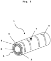
- FIG.1 a schematic view of an embodiment of the inliner 1 according to the invention is shown.
- the inliner 1 comprises an inner part 2 with a process zone 3 leading axially through the inner part, as well as a sealing sleeve 4 completely surrounding the inner part 2.
- the inner part 2 and sealing sleeve 4 are cylindrical in this embodiment and made of a metal or a metal alloy.
- the process zone 3 running axially through the entire length of the inliner 1 is also cylindrical in this embodiment and is intended for a single-screw extruder. However, other process zones can also be provided, as described above.
- Positioning holes 6 are provided on the end faces 5 of the inner part 2 in order to connect several inliners 1 to one another.
- the inliner 1 also has a radial hole 7 which opens into the process zone 3.
- the inner part 2 and the sealing sleeve 4 are cast parts.
- the sealing sleeve 4 is shrunk onto the inner part 2. It can be seen that in the surface of the inner part 2 below the A groove-shaped cooling channel 8 (shown in dashed lines) is arranged in the sealing sleeve 4, which runs spirally through the surface of the inner part 2 and is closed off to the outside by the sealing sleeve 4.
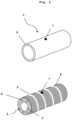
- Fig. 2 a schematic view of the separate components of an embodiment of the inliner 1 according to the invention is shown.
- a groove-shaped cooling channel 8 is arranged in the surface of the inner part 2, which runs spirally through the surface of the inner part 2 and is open to the outside.
- the cooling channel 8 is closed by the sealing sleeve 4 when the sealing sleeve 4 is applied to the inner part 2.
- the radial bore 7 is present both in the inner part 2 and in the sealing sleeve 4 and opens into the process zone 3.
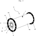
- Fig.3 a schematic view of an embodiment of the barrel 9 according to the invention is shown.
- the barrel 9 has an outer housing 9a and has a flange 10 at each end, in which positioning holes 11 are provided in order to connect several barrels 9 to one another at the end.
- the barrel 9 is cylindrical and made of a metal or a metal alloy.
- an inliner 1 is installed according to Fig.1 arranged.
- the radial bore 7 is also provided in the barrel 9, leads through the inner part 2 and the sealing sleeve 4 and opens into the process zone 3.
- Fig.4 is a schematic view of an embodiment of the extruder 13 according to the invention.
- the extruder 13 comprises several barrels 9.
- a raw material R can be fed via the dosing unit 14.
- Water or steam can be introduced into the extruder 13 via a feed 15, preferably through a radial through-channel formed by a radial bore 7 in a barrel 9.
- a cooling tool 16 is arranged at the end of the extruder 13.
- other conventional components can also be arranged at the end of the extruder. Examples include a cutting device or an end plate with a cutting device connected thereto.
- the cooling medium is preferably supplied from a tank 17 on the downstream side of the cooling tool 16 and discharged on the upstream side of the cooling tool 16. The flow direction of the cooling medium is thus opposite to the flow direction of the extrudate.
Landscapes
- Engineering & Computer Science (AREA)
- Mechanical Engineering (AREA)
- Physics & Mathematics (AREA)
- Thermal Sciences (AREA)
- Manufacturing & Machinery (AREA)
- Extrusion Moulding Of Plastics Or The Like (AREA)
Abstract
Description
- Die vorliegende Erfindung betrifft einen Inliner für einen Extruder, wobei der Inliner austauschbar ist und mindestens einen Kühlkanal aufweist.
- Extruder sind Maschinen, in denen Materialien wie Polymere, Elastomere oder proteinhaltige Mischungen für die Herstellung von Lebensmitteln einschliesslich Cerealien, Snacks, Tierfutter und alternativer Nahrungsmittel unter gewünschten Druck- und Temperaturbedingungen behandelt werden können. Ein typischer Extruder umfasst mindestens eine Extruderschneckenwelle, wobei jede der Extruderschneckenwellen einen Satz von Extruderschneckenelementen aufweist, die auf der Welle montiert sind. Die Extruderschneckenwellen sind in einem Zylinder untergebracht, welcher als Barrel bezeichnet wird. Ein Extruder umfasst üblicherweise mehrere Barrels, die Ende an Ende miteinander verbunden sind. Mehrere Barrels sind erforderlich, um die verschiedenen in dem Extruder durchzuführenden Prozesse wie Fördern, Kneten, Mischen, Entgasen, Dosieren und dergleichen auszuführen.
- Jedes Barrel umfasst ein als Inliner bezeichnetes Einsatzelement, welches in das Barrelgehäuse gepresst wird. Im Barrelgehäuse sind weiterhin Kanäle für ein Medium vorgesehen, um die Temperatur im Barrel innerhalb eines gewünschten Bereichs zu regulieren. Das in den Kanälen geführte Medium kann durch Temperiervorrichtungen wie Wärmetauscher auf eine gewünschte Temperatur gebracht werden.
- Die Inliner umfassen eine Prozesszone in Form einer axialen Bohrung, in welcher mindestens eine Extruderschneckenwelle angeordnet ist und in welcher die gewünschte Behandlung des zu extrudierenden Materials erfolgt. Da während der Extrusion die Extruderschneckenwelle innerhalb der Prozesszone rotiert und hierbei mit der Oberfläche der Prozesszone der Inliner in Berührung gerät, kommt es im Lauf der Zeit zu einem Verschleiss der Inliner.
- Um einen ordnungsgemäßen Extrusionsprozess zu gewährleisten, müssen die Inliner daher nach einer gewissen Zeit ausgetauscht werden. Da die Inliner wie vorstehend ausgeführt üblicherweise in die Barrelgehäuse gepresst sind, ist das Auswechseln eines Inliners bei herkömmlichen Barrels ein mühsamer Prozess. Typischerweise erfolgt das Einpressen des Inliners durch ein Einschrumpfen des Inliners in das Barrelgehäuse, was zu einer derart festen Anordnung des Inliners im Barrelgehäuse führt, dass bei Verschleiss das gesamte System aus Inliner und Barrelgehäuse ausgetauscht werden muss. Dies ist offensichtlich nachteilig.
- Es wurde beispielsweise in der
US 2011/0063939 A1 vorgeschlagen, einen Extruder bereitzustellen, bei welchem Inliner austauschbar in den Barrels angeordnet sind. Die vorgeschlagene Lösung umfasst ein aus zwei Teilen bestehendes Barrel, welche voneinander gelöst werden können, um einen im Barrel angeordneten Inliner austauschen zu können. - Diese Lösung ist immer noch nicht optimal. Einerseits sind besondere zweiteilige Barrels erforderlich. Andererseits ist die Temperaturregelung innerhalb des Barrels nicht optimal. Während der Extrusion entsteht in der Prozesszone der Inliner Wärme, welche abgeführt werden muss. Die in den Barrels bereitgestellten Kühlkanäle sind von den austauschbaren Inlinern beabstandet und kühlen die Prozesszone der Inliner nur indirekt.
- Es war die Aufgabe der vorliegenden Erfindung, einen Inliner für einen Extruder bereitzustellen, welcher die Nachteile des Stands der Technik überwindet und insbesondere neben einer erleichterten Austauschbarkeit eine erhöhte Temperiereffizienz aufweist. Die Aufgabe wird durch einen Inliner gemäss der vorliegenden Erfindung gelöst.
- Im Detail betrifft die vorliegende Erfindung einen Inliner für einen Extruder, umfassend ein Innenteil mit einer axial durch das Innenteil führenden Prozesszone, sowie eine das Innenteil vollständig umfänglich umgebende Dichthülse, dadurch gekennzeichnet, dass das Innenteil mindestens einen Kühlkanal aufweist.
- Der erfindungsgemässe Inliner ist zweiteilig aufgebaut. Der erfindungsgemässe Inliner umfasst eine Dichthülse und ein in der Dichthülse angeordnetes Innenteil.
- Die Dichthülse ist vorzugsweise von äusserer zylindrischer Form und so ausgestaltet, dass sie in einer vorzugsweise zylindrischen Durchgangsbohrung eines Barrels eines Extruders angeordnet und aus dieser wieder entnommen werden kann. Dies kann dadurch erreicht werden, dass der Aussendurchmesser der Dichthülse geringfügig (vorzugsweise 0,01 bis 0,5%) kleiner ist als der Durchmesser der Durchgangsbohrung des Barrels und somit die Dichthülse etwas "Spiel" in der Durchgangsbohrung des Barrels hat.
- Die Dichthülse ist aus einem Material gefertigt, welches herkömmlich für Inliner von Extrudern verwendet wird. Vorzugsweise ist die Dichthülse aus einem Metall oder einer Metall-Legierung gefertigt. Beispielsweise seien Eisen, Stahl oder Legierungen genannt, welche Aluminium, Chrom, Molybdän oder Kombinationen dieser Metalle enthalten.
- Die Dichthülse umgibt das bevorzugt zylindrische Innenteil des erfindungsgemässen Inliners vollständig umfänglich, so dass das Innenteil nicht mit dem Gehäuse des Barrels in Kontakt kommt.
- Gemäss einer bevorzugten Ausführungsform der vorliegenden Erfindung ist die Dichthülse fest auf dem Innenteil aufgebracht. Innenteil und Dichthülse können bei dieser Ausführungsform nicht separat voneinander ausgetauscht werden, sondern bilden eine untrennbare Einheit.
- Das Innenteil ist ebenfalls aus einem Material gefertigt, welches herkömmlich für Inliner von Extrudern verwendet wird. Vorzugsweise ist das Innenteil aus einem Metall oder einer Metall-Legierung gefertigt. Beispielsweise seien Eisen, Stahl oder Legierungen genannt, welche Aluminium, Chrom, Molybdän oder Kombinationen dieser Metalle enthalten.
- Die Verbindung zwischen Dichthülse und Innenteil kann auf herkömmliche Weise hergestellt werden. Gemäss einer bevorzugten Ausführungsform sind die Dichthülse und das Innenteil Gussteile und ist die Dichthülse auf das Innenteil aufgeschrumpft und optional aufgelötet oder geschweisst.
- Das Innenteil umfasst eine axial durch das Innenteil führende Prozesszone, in Form einer durchgehenden Bohrung, in welcher mindestens eine Extruderschnecke angeordnet ist. Gemäss einer bevorzugten Ausführungsform ist die Prozesszone ausgewählt aus der Gruppe bestehend aus einer zylindrischen Prozesszone und zwei teilweise überlappenden zylindrischen Prozesszonen. Dies entspricht dem Design eines Einwellenextruders beziehungsweise eines Zweiwellenextruders. Die vorliegende Erfindung ist aber nicht auf diese Varianten eingeschränkt, sondern kann auch in Mehrwellenextrudern mit mehr als zwei Extruderschnecken Anwendung finden.
- Durch die Ausgestaltung des erfindungsgemässen Inliners ist es auf einfache Weise möglich, im Innenteil des erfindungsgemässen Inliners mindestens einen Kühlkanal anzuordnen. Da das Innenteil vorzugsweise separat von der Dichthülse gefertigt wird, kann der mindestens eine Kühlkanal im Innenteil bereitgestellt werden, bevor die Dichthülse auf das Innenteil aufgebracht wird. Gemäss einer bevorzugten Ausführungsform können mehr als ein Kühlkanal, beispielsweise 2 bis 10 Kühlkanäle, im Innenteil bereitgestellt werden. Diese Kühlkanäle können miteinander verbunden sein oder Überschneidungen aufweisen. Erfindungsgemäss bevorzugt weist jeder Kühlkanal einen Durchmesser im Bereich von 5 bis 20 mm, bevorzugter 8 bis 12 mm auf.
- Gegenüber dem Stand der Technik ist der mindestens eine Kühlkanal näher an der Prozesszone des Inliners angeordnet, da er wie vorstehend ausgeführt direkt im Innenteil des Inliners (und nicht wie im Stand der Technik im Barrelgehäuse) bereitgestellt ist. Dies führt zu einer deutlichen Verbesserung der Temperiereffizienz.
- Der mindestens eine Kühlkanal kann eine Bohrung oder Nut sein, welche sich axial durch das oder aussen am Innenteil erstreckt und parallel zur Prozesszone angeordnet ist.
- Gemäss einer bevorzugten erfindungsgemässen Ausführungsform ist der mindestens eine Kühlkanal in oder an der Oberfläche des Innenteils angeordnet. Besonders bevorzugt ist der mindestens eine Kühlkanal in Form einer Kühlspirale in der Oberfläche des Innenteils angeordnet. Diese Ausführungsform ist besonders vorteilhaft in der Herstellung. Vorzugsweise wird der mindestens eine Kühlkanal als Kühlkanalteil in der Oberfläche des Innenteils bereitgestellt, besonders bevorzugt als nach aussen offene Rinne. Der mindestens eine Kühlkanalteil wird während der Herstellung des Innenteils erzeugt, beispielsweise durch Giessen des Innenteils in einer Gussform, welche entsprechende Kühlkanalteile in der Oberfläche des Innenteils erzeugt. Der mindestens eine Kühlkanalteil in der Oberfläche des Innenteils wird anschliessend durch das vorstehend beschriebene Aufbringen der Dichthülse auf das Innenteil nach aussen hin verschlossen und bildet den vollständigen Kühlkanal.
- Der erfindungsgemässe Inliner weist vorzugsweise Elemente auf, mit denen erfindungsgemässe Inliner stirnseitig miteinander verbunden werden können. Hierzu können beispielsweise an den beiden Enden des Innenteils und/oder der Dichthülse, vorzugsweise des Innenteils, Positionierbohrungen bereitgestellt sein, in denen Befestigungselemente wie Schrauben oder Stifte angeordnet werden können. Vorzugsweise weist das Innenteil des erfindungsgemässen Inliners an jeder Stirnseite 2 bis 10, besonders bevorzugt 2 bis 6 Positionierbohrungen auf.
- Gemäss einer weiteren bevorzugten Ausführungsform der vorliegenden Erfindung weist der Inliner mindestens eine radiale Bohrung auf, welche durch die Dichthülse und das Innenteil in die Prozesszone führt. Auf diese Weise wird mindestens ein radialer Durchgangskanal ausgebildet, welcher ein Materialeinlass sein kann oder zur Anordnung eines Messgeräts verwendet werden kann.
- Beispielsweise kann durch einen derart ausgebildeten Durchgangskanal Wasser oder ein Gas in das sich in der Prozesszone befindliche, zu extrudierende Material eingeleitet werden, um beispielsweise den Feuchtigkeitsgehalt des zu extrudierenden Materials einzustellen oder eine Porenbildung in dem zu extrudierenden Material zu erzeugen.
- Der erfindungsgemässe Inliner ist hinsichtlich der Anzahl und Position dieser radialen Bohrungen nicht besonders eingeschränkt. Beispielsweise können 2 bis 10, bevorzugt 3-6 radiale Bohrungen parallel oder versetzt zueinander bereitgestellt sein. Der Durchmesser einer radialen Bohrung liegt bevorzugt im Bereich von 1 mm bis 5 cm.
- Der erfindungsgemässe Inliner ist wie vorstehend beschrieben in einem Barrel angeordnet. Die vorliegende Erfindung betrifft daher auch ein Barrel für einen Extruder, umfassend ein Aussengehäuse und eine Durchgangsbohrung, dadurch gekennzeichnet, dass in der Durchgangsbohrung ein Inliner gemäss der vorliegenden Erfindung austauschbar angeordnet ist.
- Gemäss der vorliegenden Erfindung kann ein herkömmlich für Extruder eingesetztes Barrel verwendet werden. Das Barrel kann eine viereckige oder zylindrische Form haben, wobei eine zylindrische Form bevorzugt ist. Das Barrel ist aus einem Material gefertigt, welches herkömmlich für Barrel von Extrudern verwendet wird. Vorzugsweise ist das Barrel aus einem Metall oder einer Metall-Legierung gefertigt. Beispielsweise seien Eisen, Stahl oder Legierungen genannt, welche Aluminium, Chrom, Molybdän oder Kombinationen dieser Metalle enthalten.
- Am Ende des Barrels können Bauteile wie Flansche angeordnet sein, welche vorzugsweise zur stirnseitigen Verbindung von Barrels dienen. Hierzu können beispielsweise in diesen Bauteilen, vorzugsweise Flanschen, Positionierbohrungen bereitgestellt sein, in denen Befestigungselemente wie Schrauben oder Stifte angeordnet werden können. Vorzugsweise weist jedes Bauteil, vorzugsweise jeder Flansch, des erfindungsgemässen Barrels 2 bis 20, besonders bevorzugt 2 bis 16 Positionierbohrungen auf.
- Gemäss der vorliegenden Erfindung werden somit vorzugsweise sowohl die Inliner (vorzugsweise über ihre Innenteile) als auch die Barrels (über Bauteile wie Flansche) miteinander verbunden.
- Das Barrel weist eine Durchgangsbohrung auf. Die Durchgangsbohrung durchläuft das Barrel axial durch dessen gesamte Länge. In dieser Durchgangsbohrung ist ein Inliner gemäss der vorliegenden Erfindung austauschbar angeordnet. Dies kann wie vorstehend bereits beschrieben dadurch erreicht werden, dass der Aussendurchmesser der Dichthülse des Inliners geringfügig (vorzugsweise 0,01 bis 0,5%) kleiner ist als der Durchmesser der Durchgangsbohrung des Barrels und somit die Dichthülse etwas "Spiel" in der Durchgangsbohrung des Barrels hat.
- Das Barrel hat vorzugsweise eine Länge, welche der Länge des erfindungsgemässen Inliners entspricht. Mit anderen Worten schliessen die Ende des Inliners bündig mit den Ende des Barrels ab, wenn der Inliner im Barrel angeordnet ist. Es ist aber gemäss einer anderen bevorzugten Ausführungsform der vorliegenden Erfindung auch möglich, dass die axiale Länge der Barrels die axiale Länge der Inliner unterschreitet, so dass nur die Inliner aneinander anschliessend ohne Zwischenraum zwischen den Inlinern miteinander verbunden sind, während zwischen zwei aufeinander folgenden Barrels ein kleiner Spalt von vorzugsweise 0,1 mm bis 6 mm ausgebildet ist.
- Gemäss einer weiteren bevorzugten Ausführungsform der vorliegenden Erfindung weist das Barrel mindestens eine radiale Bohrung auf, welche mit der vorstehend beschriebenen radialen Bohrung des Inliners einen radialen Durchgangskanal bildet.
- Auf diese Weise wird mindestens ein radialer Durchgangskanal ausgebildet, welcher ein Materialeinlass sein kann oder zur Anordnung eines Messgeräts verwendet werden kann.
- Beispielsweise kann durch einen derart ausgebildeten Durchgangskanal Wasser oder ein Gas in das sich in der Prozesszone befindliche, zu extrudierende Material eingeleitet werden, um beispielsweise den Feuchtigkeitsgehalt des zu extrudierenden Materials einzustellen oder eine Porenbildung in dem zu extrudierenden Material zu erzeugen.
- Alternativ kann in einem derart ausgebildeten Durchgangskanal ein Messgerät angeordnet sein, beispielsweise zur Bestimmung des Drucks oder der Temperatur in der Prozesszone des Inliners. Derartige Messgeräte sind bekannt und müssen nicht näher erläutert werden.
- Das erfindungsgemässe Barrel ist hinsichtlich der Anzahl und Position dieser radialen Bohrungen nicht besonders eingeschränkt. Beispielsweise können 2 bis 10, bevorzugt 3-6 radiale Bohrungen parallel oder versetzt zueinander bereitgestellt sein. Der Durchmesser einer radialen Bohrung liegt bevorzugt im Bereich von 1 mm bis 5 cm.
- Das vorstehend beschriebene Barrel kann in jedem herkömmlichen Extruder eingesetzt werden. Die vorliegende Erfindung betrifft daher auch einen Extruder, umfassend mindestens ein vorstehend beschriebenes Barrel.
- Erfindungsgemäss umfasst der Extruder 2 bis 20 Barrel, vorzugsweise 2 bis 15 Barrels. Die Barrel sind wie vorstehend beschrieben vorzugsweise stirnseitig miteinander verbunden. Gemäss einer bevorzugten Ausführungsform der vorliegenden Erfindung sind zusätzlich die in den Barrels angeordneten Inliner stirnseitig miteinander verbunden, wie vorstehend beschrieben.
- Extruder sind hinlänglich bekannt. Es wird z.B. auf die
WO 2012/158023 A1 oder auf die Extruder, insbesondere Doppelschneckenextruder, von Bühler verwiesen. Solche Extruder haben vorzugsweise ein L/D-Verhältnis (Gesamtlänge zu Schneckendurchmesser) im Bereich von 12 -60, vorzugsweise 20 bis 40. Erfindungsgemäß werden die Extruder vorzugsweise mit 100 bis 1000 U/min, besonders bevorzugt mit 200 bis 800 U/min und besonders bevorzugt mit 20 bis 400 U/min betrieben. - Ein geeigneter Extruder umfasst mindestens eine Einheit zum Einbringen von Rohstoffen in einen ersten Abschnitt des Extruders. Sollen unterschiedliche Rohstoffe in den Extruder eingebracht werden, können auch mehrere solcher Einheiten vorgesehen sein. Der Extruder verfügt typischerweise auch über eine Wasser-, eine Öl- und gegebenenfalls eine Dampfzufuhrleitung.
- Das Gehäuse des Extruders ist vorzugsweise temperaturgesteuert. Das zu extrudierende Material wird unter Druck (üblicherweise 1 bis 400 bar, vorzugsweise 1 bis 200 bar) geknetet, um eine homogene Mischung zu bilden. Dabei wird in der Regel ein Energieaufwand von 10 bis 160 Wh/kg, vorzugsweise 10 bis 130 Wh/kg betrieben.
- Gemäß einer bevorzugten Ausführungsform der vorliegenden Erfindung kann am Ausgang des Extruders ein Kühlwerkzeug wie eine Kühldüse vorgesehen sein. Kühlwerkzeuge für Extruder sind hinreichend bekannt. Zwischen Extruder und Kühlwerkzeug kann vorzugsweise eine bekannte Verteilereinheit angeordnet sein.
- Die vorliegende Erfindung wird nachfolgend anhand von nicht einschränkenden Ausführungsbeispielen unter Bezugnahme auf Figuren näher beschrieben. In den Figuren bezeichnen gleiche Bezugszeichen gleiche Elemente. Es zeigen:
- Fig. 1
- eine schematische Ansicht einer Ausführungsform des erfindungsgemässen Inliners
- Fig. 2
- eine schematische Ansicht der separaten Komponenten einer Ausführungsform des erfindungsgemässen Inliners
- Fig. 3
- eine schematische Ansicht einer Ausführungsform des erfindungsgemässen Barrels
- Fig. 4
- eine schematische Ansicht einer Ausführungsform des erfindungsgemässen Extruders
- In
Fig. 1 ist eine schematische Ansicht einer Ausführungsform des erfindungsgemässen Inliners 1 gezeigt. Der Inliner 1 umfasst ein Innenteil 2 mit einer axial durch das Innenteil führenden Prozesszone 3, sowie eine das Innenteil 2 vollständig umfänglich umgebende Dichthülse 4. Innenteil 2 und Dichthülse 4 sind in dieser Ausführungsform zylindrisch und aus einem Metall oder einer Metall-Legierung gefertigt. Die axial die gesamte Länge des Inliners 1 durchlaufende Prozesszone 3 ist in dieser Ausführungsform ebenfalls zylindrisch und ist für einen Einwellenextruder vorgesehen. Es können aber auch andere Prozesszonen bereitgestellt werden, wie vorstehend beschrieben. An den Stirnseiten 5 des Innenteils 2 sind Positionierbohrungen 6 vorgesehen, um mehrere Inliner 1 miteinander zu verbinden. Der Inliner 1 weist zudem eine radiale Bohrung 7 auf, welche in die Prozesszone 3 mündet. - Das Innenteil 2 und die Dichthülse 4 sind Gussteile. Die Dichthülse 4 ist auf das Innenteil 2 aufgeschrumpft. Es ist zu erkennen, dass in der Oberfläche des Innenteils 2 unterhalb der Dichthülse 4 ein rinnenförmiger (gestrichelt dargestellter) Kühlkanal 8 angeordnet ist, der die Oberfläche des Innenteils 2 spiralförmig durchläuft und nach aussen durch die Dichthülse 4 abgeschlossen ist.
- In
Fig. 2 ist eine schematische Ansicht der separaten Komponenten einer Ausführungsform des erfindungsgemässen Inliners 1 gezeigt. - Es ist zu erkennen, dass in der Oberfläche des Innenteils 2 ein rinnenförmiger Kühlkanal 8 angeordnet ist, der die Oberfläche des Innenteils 2 spiralförmig durchläuft und nach aussen offen ist. Der Kühlkanal 8 wird durch die Dichthülse 4 verschlossen, wenn die Dichthülse 4 auf das Innenteil 2 aufgebracht ist.
- Die radiale Bohrung 7 ist sowohl im Innenteil 2 als auch in der Dichthülse 4 vorhanden und mündet in die Prozesszone 3.
- In
Fig. 3 ist eine schematische Ansicht einer Ausführungsform des erfindungsgemässen Barrels 9 gezeigt. Das Barrel 9 hat ein Aussengehäuse 9a und weist an beiden Enden je einen Flansch 10 auf, in welchem Positionierbohrungen 11 bereitgestellt sind, um mehrere Barrel 9 stirnseitig miteinander zu verbinden. - Das Barrel 9 ist in dieser Ausführungsform zylindrisch und aus einem Metall oder einer Metall-Legierung gefertigt.
- In der Durchgangsbohrung 12 des Barrels 9 ist ein Inliner 1 gemäss
Fig. 1 angeordnet. - Die radiale Bohrung 7 ist auch im Barrel 9 bereitgestellt, führt durch das Innenteil 2 und die Dichthülse 4 und mündet in die Prozesszone 3.
-
Fig. 4 ist eine schematische Ansicht einer Ausführungsform des erfindungsgemässen Extruders 13. Der Extruder 13 umfasst mehrere Barrels 9. Ein Rohstoff R kann über die Dosiereinheit 14 zugeführt werden. Über eine Zuführung 15 kann Wasser oder Dampf hin den Extruder 13 eingeleitet werden, vorzugsweise durch einen radialen Durchgangskanal, der durch eine radiale Bohrung 7 in einem Barrel 9 ausgebildet ist. In der Ausführungsform gemässFig. 1 ist ein Kühlwerkzeug 16 am Ende des Extruder 13 angeordnet. Selbstverständlich können auch andere herkömmliche Komponenten am Ende des Extruders angeordnet sein. Beispielhaft seien ein Schneidapparat oder eine Endplatte mit anschliessendem Schneidapparat genannt. Das Kühlmedium wird bevorzugt aus einem Tank 17 an der stromabwärtigen Seite des Kühlwerkzeugs 16 zugeführt und an der stromaufwärtigen Seite des Kühlwerkzeugs 16 abgeführt. Die Strömungsrichtung des Kühlmediums ist somit der Fliessrichtung des Extrudats entgegengesetzt.
Claims (15)
- Inliner (1) für einen Extruder (13), umfassend ein Innenteil (2) mit einer axial durch das Innenteil (2) führenden Prozesszone (3), sowie eine das Innenteil (2) vollständig umfänglich umgebende Dichthülse (4), dadurch gekennzeichnet, dass das Innenteil (2) mindestens einen Kühlkanal (8) aufweist.
- Inliner (1) nach Anspruch 1, dadurch gekennzeichnet, dass der mindestens eine Kühlkanal (8) in der Oberfläche des Innenteils (2) angeordnet ist.
- Inliner (1) nach Anspruch 2, dadurch gekennzeichnet, dass der mindestens eine Kühlkanal (8) in Form einer Kühlspirale in der Oberfläche des Innenteils (2) angeordnet ist.
- Inliner (1) nach einem der Ansprüche 1 bis 3, dadurch gekennzeichnet, dass das Innenteil (2) ein Gussstück aus Metall ist.
- Inliner (1) nach einem der Ansprüche 1 bis 4, dadurch gekennzeichnet, dass die Dichthülse (4) fest auf dem Innenteil (2) aufgebracht ist.
- Inliner (1) nach Anspruch 5, dadurch gekennzeichnet, dass die Dichthülse (4) auf das Innenteil (2) aufgeschrumpft und optional aufgelötet oder aufgeschweisst ist.
- Inliner (1) nach einem der Ansprüche 1 bis 6, dadurch gekennzeichnet, dass die Prozesszone (3) ausgewählt ist aus der Gruppe bestehend aus einer zylindrischen Prozesszone und zwei teilweise überlappenden zylindrischen Prozesszonen.
- Inliner (1) nach einem der Ansprüche 1 bis 7, dadurch gekennzeichnet, dass der Inliner (1) mindestens eine radiale Bohrung (7) aufweist, welche durch die Dichthülse (4) und das Innenteil (2) in die Prozesszone (3) führt.
- Barrel (9) für einen Extruder (13), umfassend ein Aussengehäuse (9a) und eine Durchgangsbohrung (12), dadurch gekennzeichnet, dass in der Durchgangsbohrung (12) ein Inliner (1) gemäss einem der Ansprüche 1 bis 8 austauschbar angeordnet ist.
- Barrel (9) nach Anspruch 9, dadurch gekennzeichnet, dass das Barrel (9) mindestens eine radiale Bohrung (7) aufweist, welche mit der radialen Bohrung (9) des Inliners (1) einen radialen Durchgangskanal bildet.
- Barrel (9) nach Anspruch 10, dadurch gekennzeichnet, dass der mindestens eine radiale Durchgangskanal ein Materialeinlass ist oder in dem radialen Durchgangskanal ein Messgerät angeordnet ist.
- Extruder (13), umfassend mindestens ein Barrel (9) gemäss einem der Ansprüche 9 bis 11.
- Extruder (13) nach Anspruch 12, dadurch gekennzeichnet, dass der Extruder (13) 2 bis 20 Barrel (9) umfasst, wobei die Barrel (9) stirnseitig miteinander verbunden sind.
- Extruder (13) nach Anspruch 13, dadurch gekennzeichnet, dass zusätzlich die in den Barrels (9) angeordneten Inliner (1) stirnseitig miteinander verbunden sind.
- Extruder (13) nach einem der Ansprüche 12 bis 14, dadurch gekennzeichnet, dass der Extruder (13) ausgewählt aus der Gruppe bestehend aus einem Einwellenextruder und einem Zweiwellenextruder, wobei die Extruderschnecke(n) in der Prozesszone (3) des oder der Inliner(s) (1) angeordnet ist/sind.
Priority Applications (3)
| Application Number | Priority Date | Filing Date | Title |
|---|---|---|---|
| EP23157392.4A EP4417394A1 (de) | 2023-02-17 | 2023-02-17 | Inliner für einen extruder |
| PCT/EP2024/025078 WO2024170149A1 (en) | 2023-02-17 | 2024-02-16 | Liner for an extruder |
| CN202480009854.8A CN120615052A (zh) | 2023-02-17 | 2024-02-16 | 用于挤出机的衬套 |
Applications Claiming Priority (1)
| Application Number | Priority Date | Filing Date | Title |
|---|---|---|---|
| EP23157392.4A EP4417394A1 (de) | 2023-02-17 | 2023-02-17 | Inliner für einen extruder |
Publications (1)
| Publication Number | Publication Date |
|---|---|
| EP4417394A1 true EP4417394A1 (de) | 2024-08-21 |
Family
ID=85283997
Family Applications (1)
| Application Number | Title | Priority Date | Filing Date |
|---|---|---|---|
| EP23157392.4A Pending EP4417394A1 (de) | 2023-02-17 | 2023-02-17 | Inliner für einen extruder |
Country Status (3)
| Country | Link |
|---|---|
| EP (1) | EP4417394A1 (de) |
| CN (1) | CN120615052A (de) |
| WO (1) | WO2024170149A1 (de) |
Citations (6)
| Publication number | Priority date | Publication date | Assignee | Title |
|---|---|---|---|---|
| US3900188A (en) * | 1972-11-18 | 1975-08-19 | Werner & Pfleiderer | Screw extruder housing with a wear-resistant lining |
| US20110063939A1 (en) | 2009-09-15 | 2011-03-17 | Steer Engineering Private Limited | Barrel cooling and heating system for screw extruder |
| DE202010017571U1 (de) * | 2010-07-07 | 2012-02-27 | Entex Rust & Mitschke Gmbh | Planetwalzenextrudermodul mit segmentiertem Gehäuse |
| WO2012158023A1 (en) | 2011-05-13 | 2012-11-22 | Ojah B.V. | Method of making structured protein compositions |
| US20210078230A1 (en) * | 2018-05-30 | 2021-03-18 | Inmex Gmbh | Plasticizing cylinder of a plastic extruder or an injection molding machine |
| US20220219369A1 (en) * | 2019-04-24 | 2022-07-14 | KraussMaffei Extrusion GmbH | Extrusion cylinder with means for conducting cooling or heating medium |
-
2023
- 2023-02-17 EP EP23157392.4A patent/EP4417394A1/de active Pending
-
2024
- 2024-02-16 CN CN202480009854.8A patent/CN120615052A/zh active Pending
- 2024-02-16 WO PCT/EP2024/025078 patent/WO2024170149A1/en not_active Ceased
Patent Citations (6)
| Publication number | Priority date | Publication date | Assignee | Title |
|---|---|---|---|---|
| US3900188A (en) * | 1972-11-18 | 1975-08-19 | Werner & Pfleiderer | Screw extruder housing with a wear-resistant lining |
| US20110063939A1 (en) | 2009-09-15 | 2011-03-17 | Steer Engineering Private Limited | Barrel cooling and heating system for screw extruder |
| DE202010017571U1 (de) * | 2010-07-07 | 2012-02-27 | Entex Rust & Mitschke Gmbh | Planetwalzenextrudermodul mit segmentiertem Gehäuse |
| WO2012158023A1 (en) | 2011-05-13 | 2012-11-22 | Ojah B.V. | Method of making structured protein compositions |
| US20210078230A1 (en) * | 2018-05-30 | 2021-03-18 | Inmex Gmbh | Plasticizing cylinder of a plastic extruder or an injection molding machine |
| US20220219369A1 (en) * | 2019-04-24 | 2022-07-14 | KraussMaffei Extrusion GmbH | Extrusion cylinder with means for conducting cooling or heating medium |
Also Published As
| Publication number | Publication date |
|---|---|
| WO2024170149A1 (en) | 2024-08-22 |
| CN120615052A (zh) | 2025-09-09 |
Similar Documents
| Publication | Publication Date | Title |
|---|---|---|
| DE2612827C3 (de) | Schneckenstrangpresse zur kontinuierlichen Aufbereitung und Entgasung von Elastomeren und Polymeren mit einer Viskosität über 1000 d Pa s | |
| DE2256671C2 (de) | Verfahren zum verschleißfesten Auskleiden von Extrudergehäusebohrungen und nach diesem Verfahren hergestellte Verschleißschutzauskleidung | |
| DE4325514C1 (de) | Kochextruder zur Herstellung von thermisch behandelten Biopolymeren sowie Verfahren zum Kochextrudieren von Biopolymeren | |
| DE102010026535B4 (de) | Planetwalzenextrudermodul mit segmentiertem Gehäuse | |
| EP1218186B1 (de) | Zylinder einer rotationsdruckmaschine | |
| EP1533101B2 (de) | Planetwalzenextruder zum Mischen und Extrudieren von Kunststoffen | |
| EP1620246A1 (de) | Mehrwellenextruder | |
| EP1523403B1 (de) | Extruder | |
| DE112015002161T5 (de) | Extruderschnecke, Extruder und Extrusionsverfahren | |
| EP3959060A1 (de) | Extrusionszylinder mit kühl- bzw. heizmittelführung | |
| DE10344836A1 (de) | Gerät zum Extrudieren eines keramischen Formlings | |
| DE102004041148A1 (de) | Vorrichtung zum Verteilen einer Strömung für einen Extruder | |
| DE2654774A1 (de) | Verfahren zur homogenisierung von aufgeschmolzenen polymeren und schneckenmaschine zur durchfuehrung des verfahrens | |
| DE102017005999A1 (de) | Herstellung von essbaren Wurstpellen aus Kollagen oder gleichartigen Stoffen durch Extrudieren | |
| EP0490362A1 (de) | Hochleistungsextruder mit konstanter Gangzahl im Einlauf- und Auslaufbereich eines Transferscherteiles | |
| DE69703291T2 (de) | Nebenvorrichtung für extruder | |
| DE69403704T2 (de) | Strangpresse | |
| DE3043306A1 (de) | Doppelschneckenextruder mit verschleissfestem bimetall-einsatz | |
| DE102023207736A1 (de) | Austragsvorrichtung und Verfahren zum Texturieren einer Lebensmittel-Zusammensetzung, insbesondere einer Fleischersatz-Zusammensetzung | |
| WO2023147822A1 (de) | Filtriervorrichtung für pvc-kunststoffschmelze zur verbindung mit einem doppelschneckenextruder und doppelschneckenextruder für die pvc-verarbeitung | |
| DE102017005998A1 (de) | Chemische Prozeßführung für fließfähiges Einsatzgut in einem Planetwalzenextruder | |
| EP0571750A1 (de) | Schneckenpresse | |
| WO2006042491A2 (de) | Einwellige, kontinuerlich arbeitende misch- und kraftmaschine mit konischem schaft | |
| EP4417393B1 (de) | Extruder mit dichtelement und verfahren zur herstellung eines nahrungsmittels | |
| DE102019004945A1 (de) | Modulweise oder abschnittsweise aufgebauter Extruder |
Legal Events
| Date | Code | Title | Description |
|---|---|---|---|
| PUAI | Public reference made under article 153(3) epc to a published international application that has entered the european phase |
Free format text: ORIGINAL CODE: 0009012 |
|
| STAA | Information on the status of an ep patent application or granted ep patent |
Free format text: STATUS: THE APPLICATION HAS BEEN PUBLISHED |
|
| AK | Designated contracting states |
Kind code of ref document: A1 Designated state(s): AL AT BE BG CH CY CZ DE DK EE ES FI FR GB GR HR HU IE IS IT LI LT LU LV MC ME MK MT NL NO PL PT RO RS SE SI SK SM TR |
|
| STAA | Information on the status of an ep patent application or granted ep patent |
Free format text: STATUS: REQUEST FOR EXAMINATION WAS MADE |
|
| 17P | Request for examination filed |
Effective date: 20250217 |
|
| P01 | Opt-out of the competence of the unified patent court (upc) registered |
Free format text: CASE NUMBER: APP_9380/2025 Effective date: 20250225 |