EP4412166A1 - Ressourcenzuweisungsverfahren und -vorrichtung in einem kommunikationssystem - Google Patents
Ressourcenzuweisungsverfahren und -vorrichtung in einem kommunikationssystem Download PDFInfo
- Publication number
- EP4412166A1 EP4412166A1 EP22873246.7A EP22873246A EP4412166A1 EP 4412166 A1 EP4412166 A1 EP 4412166A1 EP 22873246 A EP22873246 A EP 22873246A EP 4412166 A1 EP4412166 A1 EP 4412166A1
- Authority
- EP
- European Patent Office
- Prior art keywords
- communication
- communication device
- communication node
- information
- frequency
- Prior art date
- Legal status (The legal status is an assumption and is not a legal conclusion. Google has not performed a legal analysis and makes no representation as to the accuracy of the status listed.)
- Pending
Links
Images


Classifications
-
- H—ELECTRICITY
- H04—ELECTRIC COMMUNICATION TECHNIQUE
- H04L—TRANSMISSION OF DIGITAL INFORMATION, e.g. TELEGRAPHIC COMMUNICATION
- H04L5/00—Arrangements affording multiple use of the transmission path
-
- H—ELECTRICITY
- H04—ELECTRIC COMMUNICATION TECHNIQUE
- H04L—TRANSMISSION OF DIGITAL INFORMATION, e.g. TELEGRAPHIC COMMUNICATION
- H04L27/00—Modulated-carrier systems
- H04L27/26—Systems using multi-frequency codes
- H04L27/2601—Multicarrier modulation systems
- H04L27/2626—Arrangements specific to the transmitter only
- H04L27/2646—Arrangements specific to the transmitter only using feedback from receiver for adjusting OFDM transmission parameters, e.g. transmission timing or guard interval length
-
- H—ELECTRICITY
- H04—ELECTRIC COMMUNICATION TECHNIQUE
- H04L—TRANSMISSION OF DIGITAL INFORMATION, e.g. TELEGRAPHIC COMMUNICATION
- H04L27/00—Modulated-carrier systems
- H04L27/26—Systems using multi-frequency codes
- H04L27/2601—Multicarrier modulation systems
- H04L27/2602—Signal structure
- H04L27/2605—Symbol extensions, e.g. Zero Tail, Unique Word [UW]
- H04L27/2607—Cyclic extensions
-
- H—ELECTRICITY
- H04—ELECTRIC COMMUNICATION TECHNIQUE
- H04L—TRANSMISSION OF DIGITAL INFORMATION, e.g. TELEGRAPHIC COMMUNICATION
- H04L27/00—Modulated-carrier systems
- H04L27/26—Systems using multi-frequency codes
- H04L27/2601—Multicarrier modulation systems
- H04L27/2602—Signal structure
- H04L27/261—Details of reference signals
- H04L27/2613—Structure of the reference signals
- H04L27/26136—Pilot sequence conveying additional information
-
- H—ELECTRICITY
- H04—ELECTRIC COMMUNICATION TECHNIQUE
- H04L—TRANSMISSION OF DIGITAL INFORMATION, e.g. TELEGRAPHIC COMMUNICATION
- H04L27/00—Modulated-carrier systems
- H04L27/26—Systems using multi-frequency codes
- H04L27/2601—Multicarrier modulation systems
- H04L27/2647—Arrangements specific to the receiver only
- H04L27/2655—Synchronisation arrangements
- H04L27/2666—Acquisition of further OFDM parameters, e.g. bandwidth, subcarrier spacing, or guard interval length
-
- H—ELECTRICITY
- H04—ELECTRIC COMMUNICATION TECHNIQUE
- H04L—TRANSMISSION OF DIGITAL INFORMATION, e.g. TELEGRAPHIC COMMUNICATION
- H04L5/00—Arrangements affording multiple use of the transmission path
- H04L5/0001—Arrangements for dividing the transmission path
- H04L5/0003—Two-dimensional division
- H04L5/0005—Time-frequency
- H04L5/0007—Time-frequency the frequencies being orthogonal, e.g. OFDM(A) or DMT
-
- H—ELECTRICITY
- H04—ELECTRIC COMMUNICATION TECHNIQUE
- H04L—TRANSMISSION OF DIGITAL INFORMATION, e.g. TELEGRAPHIC COMMUNICATION
- H04L5/00—Arrangements affording multiple use of the transmission path
- H04L5/003—Arrangements for allocating sub-channels of the transmission path
- H04L5/0048—Allocation of pilot signals, i.e. of signals known to the receiver
-
- H—ELECTRICITY
- H04—ELECTRIC COMMUNICATION TECHNIQUE
- H04W—WIRELESS COMMUNICATION NETWORKS
- H04W72/00—Local resource management
- H04W72/04—Wireless resource allocation
-
- H—ELECTRICITY
- H04—ELECTRIC COMMUNICATION TECHNIQUE
- H04W—WIRELESS COMMUNICATION NETWORKS
- H04W72/00—Local resource management
- H04W72/04—Wireless resource allocation
- H04W72/044—Wireless resource allocation based on the type of the allocated resource
- H04W72/0453—Resources in frequency domain, e.g. a carrier in FDMA
-
- H—ELECTRICITY
- H04—ELECTRIC COMMUNICATION TECHNIQUE
- H04W—WIRELESS COMMUNICATION NETWORKS
- H04W72/00—Local resource management
- H04W72/20—Control channels or signalling for resource management
- H04W72/23—Control channels or signalling for resource management in the downlink direction of a wireless link, i.e. towards a terminal
-
- H—ELECTRICITY
- H04—ELECTRIC COMMUNICATION TECHNIQUE
- H04W—WIRELESS COMMUNICATION NETWORKS
- H04W72/00—Local resource management
- H04W72/50—Allocation or scheduling criteria for wireless resources
- H04W72/535—Allocation or scheduling criteria for wireless resources based on resource usage policies
Definitions
- the present disclosure relates to a communication technique in a communication system, and more particularly, to a technique for resource allocation considering temporal broadening in a communication system.
- Typical wireless communication technologies include long term evolution (LTE), new radio (NR), 6th generation (6G) communication, and/or the like.
- LTE long term evolution
- NR new radio
- 6G 6th generation
- the LTE may be one of 4th generation (4G) wireless communication technologies
- the NR may be one of 5th generation (5G) wireless communication technologies.
- radio frequency bands used for wireless communication in the 5G (or NR) communication specifications may be broadly classified into frequency range 1 (FR1) bands and frequency range 2 (FR2) bands.
- FR1 bands may refer to relatively low frequency bands as compared to the FR2 bands, which are of about 7 GHz or below.
- the FR2 bands may refer to relatively high frequency bands as compared to the FR1 bands, which are of about 7 GHz or above.
- the FR2 bands may be 28-29 GHz bands, which include unlicensed bands, millimeter wave bands, and terahertz wave bands.
- the present disclosure is directed to providing a method and an apparatus of allocating resources for efficient operations of a high frequency band.
- the present disclosure is directed to providing a method and an apparatus of operating resources that resolve problems such as temporal broadening or path loss in a communication system using a millimeter wave band and/or terahertz wave band.
- the present disclosure is directed to providing a method and an apparatus of determining a cyclic prefix (CP) symbol in a communication using a millimeter wave band and/or terahertz wave band and using an orthogonal frequency division multiplexing (OFDM) scheme.
- CP cyclic prefix
- OFDM orthogonal frequency division multiplexing
- a method according to the present disclosure may comprise: transmitting a first signal block including a pilot signal at a preset periodicity; receiving information on a temporal broadening of the pilot signal from a second communication node; allocating a communication resource to the second communication node based on the information on the temporal broadening when communication with the second communication node is required; and communicating with the second communication node using the allocated communication resource.
- the information on the temporal broadening may be information on a time Ts' during which the pilot signal is measured at the second communication device.
- the first signal block may include information on a transmission time Ts of the pilot signal.
- the information on the temporal broadening may be information on a ratio of the transmission time Ts of the pilot signal to a time Ts' during which the pilot signal is measured at the second communication device.
- the communication resource may be allocated to the second communication node based on a predetermined mapping rule, and the predetermined mapping rule may be configured to: divide a ratio of a transmission time Ts of the pilot signal to a time Ts' during which the pilot signal is measured at the second communication device into n predetermined ranges (n is 2 or more); divide frequency resources allocatable by the first communication node into the n ranges; map the frequency resources to the n ranges of the ratio in order from high frequency to low frequency; and map the ratio of the transmission time Ts of the pilot signal to the time Ts' during which the pilot signal is measured at the second communication device to the n ranges from small to high values.
- the first communication node may determine one of three or more types of Cyclic Prefix (CP) symbol based on the information on the temporal broadening when allocating the communication resource.
- OFDM Orthogonal Frequency Division Multiplexing
- the communication resource may be allocated to the second communication node based on a predetermined mapping rule, and the predetermined mapping rule may be configured to: divide a distance between the first communication node and the second communication node into a predetermined plurality of first ranges; divide frequency resources allocatable by the first communication node into the first ranges from high frequency to low frequency; map the frequency resources to the first ranges in order from high frequency to low frequency; and map the distance to the first ranges from a closest distance to a farthest distance.
- the communication resource may be allocated based on a latency requirement of a service requested by the second communication node when allocating the communication resource.
- the operation method may further comprise: transmitting information on a frequency resource set for transmitting the pilot signal before transmitting the first signal block.
- An apparatus as a first communication node in a communication system, may comprise: a transceiver configured to transmit and receive signals to and from at least one second communication node; and at least one processor, wherein the at least one processor may be configured to: control the transceiver to transmit a first signal block including a pilot signal at a preset periodicity; control the transceiver to receive information on a temporal broadening of the pilot signal from a second communication node; allocate a communication resource to the second communication node based on the information on the temporal broadening when communication with the second communication node is required; and control the transceiver to communicate with the second communication node via the allocated communication resource.
- the information on the temporal broadening may be information on a time Ts' during which the pilot signal is measured at the second communication device.
- the first signal block may include information on a transmission time Ts of the pilot signal.
- the information on the temporal broadening may be information on a ratio of the transmission time Ts of the pilot signal to a time Ts' during which the pilot signal is measured at the second communication device.
- the at least one processor may allocate the communication resource to the second communication node based on a predetermined mapping rule, and the predetermined mapping rule may be configured to: divide a ratio of a transmission time Ts of the pilot signal to a time Ts' during which the pilot signal is measured at the second communication device into n predetermined ranges (n is 2 or more); divide frequency resources allocatable by the first communication node into the n ranges; map the frequency resources to the n ranges of the ratio in order from high frequency to low frequency; and map the ratio of the transmission time Ts of the pilot signal to the time Ts' during which the pilot signal is measured at the second communication device to the n ranges from small to high values.
- the at least one processor may determine one of three or more types of Cyclic Prefix (CP) symbol based on the information on the temporal broadening when allocating the communication resource.
- CP Cyclic Prefix
- the at least one processor may allocate the communication resource to the second communication node based on a predetermined mapping rule, and the predetermined mapping rule may be configured to: divide a distance between the first communication node and the second communication node into a predetermined plurality of first ranges, divide frequency resources allocatable by the first communication node into the first ranges from high frequency to low frequency; map the frequency resources to the first ranges in order from high frequency to low frequency; and map the distance to the first ranges from a closest distance to a farthest distance.
- the predetermined mapping rule may be configured to: divide a distance between the first communication node and the second communication node into a predetermined plurality of first ranges, divide frequency resources allocatable by the first communication node into the first ranges from high frequency to low frequency; map the frequency resources to the first ranges in order from high frequency to low frequency; and map the distance to the first ranges from a closest distance to a farthest distance.
- the at least one processor may allocate the communication resource based on a latency requirement of a service requested by the second communication node or a service to be provided to the second communication node when allocating the communication resource.
- the at least one processor may further transmit information on a frequency resource set for transmitting the pilot signal before transmitting the first signal block.
- An operation method of a first communication node in a communication system may comprise: receiving a first signal block including a pilot signal from a second communication node; measuring information on a temporal broadening based on a reception time of the pilot signal; providing the information on the temporal broadening to the second communication node; and in response to a communication resource allocated from the second communication node, communicating with the second communication node based on the allocated resource.
- the information on the temporal broadening may be information on a ratio of a transmission time Ts of the pilot signal to a time Ts' during which the pilot signal is measured.
- the resource allocation method and apparatus can resolve problems such as temporal broadening or path loss in a communication system using a millimeter wave band and/or terahertz wave band.
- an appropriate CP suitable for a delay can be determined in a communication system using a millimeter Wave band and/or terahertz wave band and using the OFDM scheme. Through this, communication performance in the high frequency band can be improved.
- a communication system to which exemplary embodiments according to the present disclosure are applied will be described.
- the communication system to which the exemplary embodiments according to the present disclosure are applied is not limited to the contents described below, and the exemplary embodiments according to the present disclosure may be applied to various communication systems.
- the communication system may have the same meaning as a communication network.
- a network may include, for example, a wireless Internet such as wireless fidelity (WiFi), mobile Internet such as a wireless broadband Internet (WiBro) or a world interoperability for microwave access (WiMax), 2G mobile communication network such as a global system for mobile communication (GSM) or a code division multiple access (CDMA), 3G mobile communication network such as a wideband code division multiple access (WCDMA) or a CDMA2000, 3.5G mobile communication network such as a high speed downlink packet access (HSDPA) or a high speed uplink packet access (HSUPA), 4G mobile communication network such as a long term evolution (LTE) network or an LTE-Advanced network, 5G mobile communication network, B5G mobile communication network (6G communication network, etc.), or the like.
- a wireless Internet such as wireless fidelity (WiFi), mobile Internet such as a wireless broadband Internet (WiBro) or a world interoperability for microwave access (WiMax)
- 2G mobile communication network such as a global system
- a terminal may refer to a mobile station, mobile terminal, subscriber station, portable subscriber station, user equipment, access terminal, or the like, and may include all or a part of functions of the terminal, mobile station, mobile terminal, subscriber station, mobile subscriber station, user equipment, access terminal, or the like.
- a desktop computer laptop computer, tablet PC, wireless phone, mobile phone, smart phone, smart watch, smart glass, e-book reader, portable multimedia player (PMP), portable game console, navigation device, digital camera, digital multimedia broadcasting (DMB) player, digital audio recorder, digital audio player, digital picture recorder, digital picture player, digital video recorder, digital video player, or the like having communication capability may be used as the terminal.
- PMP portable multimedia player
- DMB digital multimedia broadcasting
- the base station may refer to an access point, radio access station, node B (NB), evolved node B (eNB), base transceiver station, mobile multihop relay (MMR)-BS, or the like, and may include all or part of functions of the base station, access point, radio access station, NB, eNB, base transceiver station, MMR-BS, or the like.
- NB node B
- eNB evolved node B
- MMR mobile multihop relay
- FIG. 1 is a conceptual diagram illustrating an exemplary embodiment of a communication system.
- a communication system 100 may comprise a plurality of communication nodes 110-1, 110-2, 110-3, 120-1, 120-2, 130-1, 130-2, 130-3, 130-4, 130-5, and 130-6.
- the communication system 100 may further comprise a core network (e.g. a serving gateway (S-GW), a packet data network (PDN) gateway (P-GW), and a mobility management entity (MME)).
- a core network e.g. a serving gateway (S-GW), a packet data network (PDN) gateway (P-GW), and a mobility management entity (MME)
- S-GW serving gateway
- PDN packet data network gateway
- MME mobility management entity
- the core network may include an access and mobility management function (AMF), a user plane function (UPF), a session management function (SMF), and the like.
- AMF access and mobility management function
- UPF user plane function
- SMF session management function
- the plurality of communication nodes 110 to 130 may support communication protocols defined in the 3rd generation partnership project (3GPP) technical specifications (e.g. LTE communication protocol, LTE-A communication protocol, NR communication protocol, or the like).
- the plurality of communication nodes 110 to 130 may support code division multiple access (CDMA) based communication protocol, wideband CDMA (WCDMA) based communication protocol, time division multiple access (TDMA) based communication protocol, frequency division multiple access (FDMA) based communication protocol, orthogonal frequency division multiplexing (OFDM) based communication protocol, filtered OFDM based communication protocol, cyclic prefix OFDM (CP-OFDM) based communication protocol, discrete Fourier transform-spread-OFDM (DFT-s-OFDM) based communication protocol, orthogonal frequency division multiple access (OFDMA) based communication protocol, single carrier FDMA (SC-FDMA) based communication protocol, non-orthogonal multiple access (NOMA) based communication protocol, generalized frequency division multiplexing (
- FIG. 2 is a block diagram illustrating an exemplary embodiment of a communication node constituting a communication system.
- an apparatus 200 may comprise at least one processor 210, a memory 220, and a transceiver 230 connected to the network for performing communications. Also, the apparatus 200 may further comprise an input interface device 240, an output interface device 250, a storage device 260, and the like. The respective components included in the apparatus 200 may communicate with each other as connected through a bus 270.
- the processor 210 may execute a program stored in at least one of the memory 220 and the storage device 260.
- the processor 210 may refer to a central processing unit (CPU), a graphics processing unit (GPU), or a dedicated processor on which methods in accordance with embodiments of the present disclosure are performed.
- Each of the memory 220 and the storage device 260 may be constituted by at least one of a volatile storage medium and a non-volatile storage medium.
- the memory 220 may comprise at least one of read-only memory (ROM) and random access memory (RAM).
- the communication system 100 may comprise a plurality of base stations 110-1, 110-2, 110-3, 120-1, and 120-2, and a plurality of terminals 130-1, 130-2, 130-3, 130-4, 130-5, and 130-6.
- Each of the first base station 110-1, the second base station 110-2, and the third base station 110-3 may form a macro cell, and each of the fourth base station 120-1 and the fifth base station 120-2 may form a small cell.
- the fourth base station 120-1, the third terminal 130-3, and the fourth terminal 130-4 may belong to the cell coverage of the first base station 110-1.
- the second terminal 130-2, the fourth terminal 130-4, and the fifth terminal 130-5 may belong to the cell coverage of the second base station 110-2.
- the fifth base station 120-2, the fourth terminal 130-4, the fifth terminal 130-5, and the sixth terminal 130-6 may belong to the cell coverage of the third base station 110-3.
- the first terminal 130-1 may belong to the cell coverage of the fourth base station 120-1
- the sixth terminal 130-6 may belong to the cell coverage of the fifth base station 120-2.
- each of the plurality of base stations 110-1, 110-2, 110-3, 120-1, and 120-2 may be referred to as NodeB (NB), evolved NodeB (eNB), gNB, advanced base station (ABS), high reliability-base station (HR-BS), base transceiver station (BTS), radio base station, radio transceiver, access point (AP), access node, radio access station (RAS), mobile multihop relay-base station (MMR-BS), relay station (RS), advanced relay station (ARS), high reliability-relay station (HR-RS), home NodeB (HNB), home eNodeB (HeNB), road side unit (RSU), radio remote head (RRH), transmission point (TP), transmission and reception point (TRP), or the like.
- NB NodeB
- eNB evolved NodeB
- gNB advanced base station
- ABS high reliability-base station
- HR-BS base transceiver station
- AP access node
- RAS mobile multihop relay-base station
- RS relay station
- Each of the plurality of terminals 130-1, 130-2, 130-3, 130-4, 130-5, and 130-6 may be referred to as user equipment (UE), terminal equipment (TE), advanced mobile station (AMS), high reliability-mobile station (HR-MS), terminal, access terminal, mobile terminal, station, subscriber station, mobile station, portable subscriber station, node, device, on-board unit (OBU), or the like.
- UE user equipment
- TE terminal equipment
- AMS advanced mobile station
- HR-MS high reliability-mobile station
- OBU on-board unit
- each of the plurality of base stations 110-1, 110-2, 110-3, 120-1, and 120-2 may operate in the same frequency band or in different frequency bands.
- the plurality of base stations 110-1, 110-2, 110-3, 120-1, and 120-2 may be connected to each other via an ideal backhaul link or a non-ideal backhaul link, and exchange information with each other via the ideal or non-ideal backhaul.
- each of the plurality of base stations 110-1, 110-2, 110-3, 120-1, and 120-2 may be connected to the core network through the ideal backhaul link or non-ideal backhaul link.
- Each of the plurality of base stations 110-1, 110-2, 110-3, 120-1, and 120-2 may transmit a signal received from the core network to the corresponding terminal 130-1, 130-2, 130-3, 130-4, 130-5, or 130-6, and transmit a signal received from the corresponding terminal 130-1, 130-2, 130-3, 130-4, 130-5, or 130-6 to the core network.
- each of the plurality of base stations 110-1, 110-2, 110-3, 120-1, and 120-2 may support a multi-input multi-output (MIMO) transmission (e.g. single-user MIMO (SU-MIMO), multi-user MIMO (MU-MIMO), massive MIMO, or the like), a coordinated multipoint (CoMP) transmission, a carrier aggregation (CA) transmission, a transmission in unlicensed band, a device-to-device (D2D) communication (or, proximity services (ProSe)), an Internet of Things (IoT) communication, a dual connectivity (DC), or the like.
- MIMO multi-input multi-output
- SU-MIMO single-user MIMO
- MU-MIMO multi-user MIMO
- massive MIMO massive MIMO
- CoMP coordinated multipoint
- CA carrier aggregation
- D2D device-to-device
- ProSe proximity services
- IoT Internet of Things
- DC dual connectivity
- each of the plurality of terminals 130-1, 130-2, 130-3, 130-4, 130-5, and 130-6 may perform operations corresponding to operations of the plurality of base stations 110-1, 110-2, 110-3, 120-1, and 120-2, operations supported by the plurality of base stations 110-1, 110-2, 110-3, 120-1, and 120-2, or the like.
- the second base station 110-2 may transmit a signal to the fourth terminal 130-4 in the SU-MIMO manner
- the fourth terminal 130-4 may receive the signal from the second base station 110-2 in the SU-MIMO manner.
- the second base station 110-2 may transmit a signal to the fourth terminal 130-4 and fifth terminal 130-5 in the MU-MIMO manner, and the fourth terminal 130-4 and fifth terminal 130-5 may receive the signal from the second base station 110-2 in the MU-MIMO manner.
- Each of the first base station 110-1, the second base station 110-2, and the third base station 110-3 may transmit a signal to the fourth terminal 130-4 in the CoMP transmission manner, and the fourth terminal 130-4 may receive the signal from the first base station 110-1, the second base station 110-2, and the third base station 110-3 in the CoMP manner.
- each of the plurality of base stations 110-1, 110-2, 110-3, 120-1, and 120-2 may exchange signals with the corresponding terminals 130-1, 130-2, 130-3, 130-4, 130-5, or 130-6 which belongs to its cell coverage in the CA manner.
- Each of the base stations 110-1, 110-2, and 110-3 may control D2D communications between the fourth terminal 130-4 and the fifth terminal 130-5, and thus the fourth terminal 130-4 and the fifth terminal 130-5 may perform the D2D communications under control of the second base station 110-2 and the third base station 110-3.
- the corresponding second communication node may perform a method (e.g. reception or transmission of the data packet) corresponding to the method performed at the first communication node. That is, when an operation of a terminal is described, the corresponding base station may perform an operation corresponding to the operation of the terminal. Conversely, when an operation of the base station is described, the corresponding terminal may perform an operation corresponding to the operation of the base station.
- radio frequency bands used for wireless communication in the 5G (or NR) communication specifications may be broadly classified into frequency range 1 (FR1) bands and frequency range 2 (FR2) bands.
- FR1 bands may refer to relatively low frequency bands as compared to the FR2 bands, which are of about 7 GHz or below.
- the FR2 bands may refer to relatively high frequency bands as compared to the FR1 bands, which are of about 7 GHz or above.
- the FR2 bands may be 28-29 GHz bands, which include unlicensed bands, millimeter wave bands, and terahertz wave bands.
- the FR1 bands and FR2 bands may be defined as in Table 1.
- Table 1 Frequency Range (FR) Corresponding frequency range FR1 410 MHz ⁇ 7125 MHz FR2 24250 MHz ⁇ 52600 MHz
- conditions or requirements for radio communication may be defined identically or differently for the FR1 band and FR2 band.
- Operating bands in which communication nodes can communicate in the FR1 band may be defined as shown in Tables 2 and 3.
- NR operating band Uplink (UL) operating band BS receive / UE transmit Downlink (DL) operating band BS transmit / UE receive Duplex mode F UL,low - F UL,high F DL,low - F DL,high n1 1920 MHz - 1980 MHz 2110 MHz - 2170 MHz FDD n2 1850 MHz - 1910 MHz 1930 MHz - 1990 MHz FDD n3 1710 MHz - 1785 MHz 1805 MHz - 1880 MHz FDD n5 824 MHz - 849 MHz 869 MHz - 894 MHz FDD n7 2500 MHz - 2570 MHz 2620 MHz - 2690 MHz FDD n8 880 MHz - 915 MHz 925 MHz - 960 MHz FDD n12 699 MHz - 716 MHz 729 MHz - 746 MHz FDD n13 777 MHz - 787 MHz 746 MHz - 7
- Narrowband-Internet of Thing may operate in n1, n2, n3, n5, n7, n8, n12, n13, n14, n18, n20, n25, n26, n28, n41, n65, n66, n70, n71, n74, and/or n90 among the operating bands shown in Table 2 and Table 3 above.
- NR operating band Uplink (UL) and Downlink (DL) operating band BS transmit/receive UE transmit/receive Duplex mode F UL,low - F UL,high F DL,low - F DL,high n257 26500 MHz - 29500 MHz TDD n258 24250 MHz - 27500 MHz TDD n259 39500 MHz - 43500 MHz TDD n260 37000 MHz - 40000 MHz TDD n261 27500 MHz - 28350 MHz TDD n262 47200 MHz - 48200 MHz TDD
- a channel bandwidth, and the like may be configured differently. As described above, in the NR communication specification, an appropriate operating band is allocated and operated according to a use and purpose of a communication environment.
- FIG. 3 is a conceptual diagram illustrating a channel bandwidth in the NR communication system.
- a horizontal axis represents a frequency (f) band, and one channel bandwidth 300 corresponding to the frequency axis in the NR communication system is illustrated.
- the channel bandwidth 300 illustrated in FIG. 3 may be a base station (BS) channel bandwidth.
- the BS channel bandwidth may support one or more radio frequency (RF) carriers for downlink transmission or uplink reception of a base station.
- RF radio frequency
- UE channel bandwidths For transmission and reception of one or more user equipments (UEs) (or terminals) connected to the base station, different UE channel bandwidths (or UE bandwidths) may be configured within the same spectrum as the BS channel bandwidth.
- the UE channel bandwidth for each UE may be configured statically or flexibly within the spectrum of the BS channel bandwidth for the base station to which the UE is connected.
- the channel bandwidth 300 may include a transmission bandwidth configuration 310 capable of actually transmitting data.
- the transmission bandwidth configuration may include a plurality of carrier resource blocks (or resource blocks) 312.
- the base station may configure the UE channel bandwidth by allocating arbitrary carrier resource blocks within the transmission bandwidth configuration 310 to a specific UE. Accordingly, the base station may perform transmission and/or reception with the UE using resource blocks allocated to the UE channel bandwidth, for example, one or more resource blocks.
- one or more UE bandwidths (or UE bandwidth parts) each composed of resource blocks smaller than or equal to resource blocks constituting an RF carrier of the BS channel bandwidth may be configured within the BS channel bandwidth.
- Each UE may perform uplink or downlink communication with the base station through one or more UE bandwidths (or UE bandwidth parts) configured for the UE.
- two or more channel bandwidths may be separated by channel edges in the frequency domain.
- Each channel bandwidth may be composed of a first guard band 321, the transmission bandwidth configuration 310, a second guard band 322, and the like.
- the first guard band 321 and the second guard band 322 may be configured symmetrically or asymmetrically. In other words, within one channel bandwidth, the first guard band 321 and the second guard band 322 may have the same or different sizes.
- the transmission bandwidth configuration 310 may be arranged between the first guard band 321 and the second guard band 322.
- the transmission bandwidth configuration 310 may refer to a set of resource blocks that can be used for transmission and reception within the channel bandwidth.
- the transmission bandwidth configuration may be composed of N RB resource blocks (RB).
- N RB may be a natural number greater than or equal to 1.
- the transmission bandwidth configuration 310 may include a transmission bandwidth 311 consisting of one or more active RBs. Information or signals may be transmitted and received through one or more active RBs constituting one or more transmission bandwidths.
- a value of N RB the size of the transmission bandwidth configuration 311, may be determined according to the size of BS channel bandwidth (MHz) and the size of subcarrier spacing (SCS) (kHz).
- Table 5 and Table 6 below exemplify values of N RB , the size of the transmission bandwidth configuration in the FR1 band and FR2 band, respectively.
- conditions or requirements for transmission and reception of the base station or UE may be defined based on the transmission bandwidth configuration determined based on Table 5 or Table 6.
- a transmitter of the NR communication system transmits data using OFDM symbols.
- a receiver of the NR communication system may receive the OFDM symbols and extract data from the received OFDM symbols.
- an OFDM symbol may generally be classified into a form to which a cyclic prefix (CP) is added and a form without a CP.
- CP cyclic prefix
- an OFDM symbol may refer to an OFDM symbol according to the CP-OFDM scheme.
- the CP may be used to remove inter-symbol interference (ISI) occurring due to a delay caused by multi-path propagation during signal transmission, by copying a last part of the OFDM symbol corresponding to a CP length and adding it to a start part of the OFDM symbol. Therefore, the CP length may be determined depending on a coverage (i.e. range or width thereof), frequency characteristics (or frequency band), and/or the like of the base station.
- ISI inter-symbol interference
- a normal CP and an extended CP are defined.
- the normal CP may be used for all SCSs, and the extended CP may be supported only for an SCS of 60 kHz or higher.
- the same CP length may be used in an active downlink bandwidth part (DL BWP) and an active uplink bandwidth part (UL BWP) within the base station, excluding a supplementary uplink (SUL).
- a wider frequency band than before such as an unlicensed band of millimeter waves or a terahertz frequency band
- an extreme path loss may occur in a specific frequency band.
- a transmitted signal (or information) subjected to Fourier transform may undergo frequency-selective high attenuation in the frequency domain, and then may be transmitted after being inverse-Fourier-transformed. Accordingly, a temporal broadening phenomenon occurs in which a received signal becomes longer than the transmitted signal.
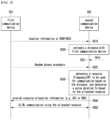
- FIG. 4 is a diagram illustrating a signal flow for determining a frequency and/or CP length for communication between communication devices according to an exemplary embodiment of the present disclosure.
- each of a first communication device 401 and a second communication device 402 may be at least one of the communication devices 110-1, 110-2, 110-3, 120-1, 120-2, 130-1, 130-2, 130-3, 130-4, 130-5, and 200 previously described in FIGS. 1 and 2 .
- the signal flow illustrated in FIG. 4 may be applied to the NR communication, an example of 5G communication that is currently being developed and whose services are provided. In addition, it may also be used in 6G communication, which is expected to use a higher frequency band than the 5G communication in the future.
- Both the first communication device 401 and the second communication 402 described below may be specific terminals and/or UEs.
- first communication device 401 and the second communication device 402 are both terminals (or UEs)
- a form of communication without a base station such as direct (e.g. D2D) communication between terminals, IoT, and/or V2X, may be performed.
- direct (e.g. D2D) communication between terminals, IoT, and/or V2X may be performed.
- the present disclosure may also be applied to such communication schemes between terminals.
- the first communication device 401 is assumed to be a UE
- the second communication device 402 is assumed to be a base station equipment.
- the second communication 402 is a gNB, which is a base station equipment according to the NR communication specification among various base station equipments. Therefore, in the following description, the second communication device 402 may be understood as a gNB.
- the present disclosure may also be applied to 6G communication, which is expected to use a high frequency such as NR or a higher frequency band, without being limited to the NR communication.
- it may be applied to any wireless communication system that can adopt the methods described below.
- the second communication device 402 may transmit a master information block (MIB) at a predetermined periodicity (S410).
- MIB master information block
- the MIB transmitted in the step S410 may include information on a reference frequency set according to the present disclosure.
- the reference frequency set may be exemplified as shown in Table 7 below. [Table 7] Reference frequency Index F REF #1 0 F REF #2 1 F REF #3 2 F REF #4 3
- reference frequencies may be a set of specific frequencies for measuring temporal broadening in one operating band according to the present disclosure.
- the temporal broadening may mean a phenomenon in which a signal received by a receiver becomes temporally longer than a transmitted signal.
- the reference frequency set may be, for example, a set of specific frequencies for measuring temporal broadening in one specific operating band illustrated in Tables 2 to 3 described above.
- the reference frequency set may be a set of specific frequencies for measuring temporal broadening across the entire band that the second communication device 402 can use.
- F REF #1, F REF #2, F REF #3, and F REF #4 exemplified in Table 7 exist within one operating band.
- the four reference frequencies F REF #1, F REF #2, F REF #3, and F REF #4 exemplified in Table 7 are merely an example, and the present disclosure is not limited to the number of reference frequencies exemplified above.
- the second communication device 402 may configure a plurality of reference frequencies within one operating band as exemplified in Table 7. Even in the case of having a plurality of reference frequencies within one operating band, it is not necessary to have four reference frequencies. For example, two or three reference frequencies and/or five or more reference frequencies may be configured within one operating band. Therefore, the number of reference frequencies exemplified in Table 7 is for illustrative purposes only and is not intended to limit the present disclosure.
- the second communication device 402 may configure and announce the reference frequency set information exemplified in Table 7 by transmitting the MIB at a preset periodicity in the step S410.
- the reference frequency set information may be informed to the first communication device 401 in various forms. For example, a preconfigured mapping rule may be used between specific information included in the MIB and the reference frequency set information. For example, it may be assumed that the MIB includes first information, second information, and third information. In this case, the reference frequency set information may be mapped based on the technical specification according to the configuration of the first information, second information, and third information. In this case, information such as Table 7 may be implicitly informed.
- the reference frequency set information may be transmitted as being explicitly included in the MIB.
- the first communication device 401 and the second communication device 402 may know the reference frequency set in advance. Therefore, the reference frequency set information may not be transmitted.
- the second communication device 402 may inform an index of each reference frequency by informing the reference frequency set through the MIB or a signal broadcast (or transmitted) to terminals in the step S410.
- an index may be assigned to each reference frequency to identify the respective two reference frequencies F REF #1 and F REF #2.
- step S410 whether to transmit the reference frequency set information and whether to transmit index information therefor may be optionally implemented, depending on how it is defined in the communication specification.
- the second communication device 402 may select a specific reference frequency to transmit a synchronization signal block (SSB) (S420). For example, if there are four reference frequencies F REF #1, F REF #2, F REF #3, and F REF #4 within one operating band as shown in Table 7, the second communication device 402 may determine at which reference frequency to transmit a pilot signal according to the present disclosure.
- the pilot signal may be a reference signal for measuring temporal broadening.
- the second communication device 402 can use four reference frequencies F REF #1, F REF #2, F REF #3, and F REF #4 within one operating band as shown in Table 7, it may also select all of the four reference frequencies.
- the pilot signal according to an exemplary embodiment of the present disclosure may use RS(s) defined in the NR communication specification.
- the NR technical specification defines various types of RS, and the present disclosure exemplifies a case of using an RS transmitted through the SSB.
- the present disclosure is not limited to just the RS of SSB, and a signal periodically broadcast (or transmitted) from the base station to the terminal may be used as the pilot signal.
- the pilot signal is an RS. Therefore, in the following description, when an RS signal is mentioned without special distinction, it may be understood as a pilot signal according to the present disclosure.
- the second communication device 402 may determine a pulse duration Ts of the pilot signal (S420).
- the pulse duration may be determined based on an SCS when it is determined based on the NR technical specification.
- the pulse duration of the pilot signal may be determined separately to detect temporal broadening.
- the pulse duration Ts is determined according to the SPS of the NR communication specification, determining of the pulse duration Ts may be omitted in the step S420.
- the second communication device 402 that is, the base station, may determine the pulse duration Ts.
- the second communication device 402 may or may not notify information on the pulse duration Ts to the first communication device 401.
- the second communication device 402 when the second communication device 402 determines the pulse duration Ts of the pilot signal to an arbitrary value, the second communication device 402 may determine the same pulse duration for all reference frequencies within the same one operating band. According to another exemplary embodiment of the present disclosure, the second communication device 402 may determine to have a different pulse duration Ts for each reference frequency within the same operating band.
- the second communication device 402 may determine a threshold for measuring the pulse duration Ts in the step S410.
- a receiver may receive the pilot signal for a longer time than the pulse duration Ts of the pilot signal transmitted from the transmitter.
- temporal broadening of the pilot signal may occur.
- the second communication device 402 may need to be able to know the temporal broadening, that is, the lengthened time, of the pilot signal received from the first communication device 401. It may be required necessary to determine a threshold for detecting the pulse duration of the pilot signal in the first communication device 401.
- the threshold for detecting the pulse duration may be preset between the first communication device 401 and the second communication device 402. According to another exemplary embodiment of the present disclosure, the threshold for detecting the pulse duration may be set by the first communication device 401 and provided to the second communication device 402. The threshold for detecting the pulse duration may be preset between the first communication device 401 and the second communication device 402, or may be determined by the second communication device 402 and notified to the first communication device 1401. Therefore, setting of the threshold may also be optionally performed in the step S420.
- the threshold for the pilot signal will be described in more detail.
- the pilot signal is information known to each other between a transmitter and a receiver. Therefore, when the transmitter, that is, the second communication device 402, transmits the pilot signal, the receiver, that is, the first communication device 401, may perform auto-correlation with respect to the pilot signal that is known in advance and obtain an estimation Ts' of the pulse duration.
- an auto-correlation value may be most often set to 0.1%, that is, -30dB interference level.
- the pulse duration measurement value Ts' of the pilot signal may be obtained as follows.
- the first communication device 401 may perform auto-correlation for the pilot signal in advance before a period in which the pilot signal is transmitted, and may identify that the pilot signal is actually transmitted from a time at which a -30dB interference level is initially exceeded. Even after identifying that the pilot signal is transmitted, the first communication device 401 may continue to perform auto-correlation. The first communication device 401 may identify a time at which the interference level is below (or equal to or below) -30 dB as a result of the continuous auto-correlation.
- the first communication device 401 may use a time counted from the time at which the auto-correlation result first exceeds (or becomes equal to or greater than) the -30dB interference level to the time at which it falls below (or becomes equal to or lower than) the -30dB interference level to obtain (or calculate) the pulse duration measurement value Ts' during which the pilot signal is transmitted.
- the threshold for auto-correlation may be preset to a specific value, or the second communication device 402 may determine another specific value as the threshold. If a preset threshold is used, both the first communication device 401 and the second communication device 402 know the threshold, so they may be configured not to transmit the threshold. As another example, if a preset threshold is not used, the second communication device 402 may need to determine a threshold and inform the first communication device 401 of the threshold.
- the second communication device 402 may transmit SSB(s) (S430).
- a frequency at which the SSB(s) are transmitted may be the reference frequency described in Table 7.
- the SSB transmitted in the step S430 may include at least one of the following information according to the present disclosure.
- the second communication device 402 may include a pilot signal with a specific pulse duration Ts when transmitting the SSB in the step S430.
- the SSB may include information on the pulse duration Ts.
- the second communication device 402 may not include information on the pulse duration Ts in the SSB even when the pulse duration Ts is set by the second communication device 402.
- the case where the information on the pulse duration is provided to the first communication device 401, which is a UE, according to the present disclosure may correspond to a case where the first communication device 401 calculates a temporal broadening factor (TBF) to be described later.
- TBF temporal broadening factor
- the case where the information on the pulse duration is not provided to the first communication device 401 according to the present disclosure may correspond to a case where the second communication device 402, which is a base station, directly calculates the TBF.
- the SSB may include information on the threshold.
- the SSB may include information on TBF section(s) and information on TBF indicator(s).
- the TBF according to the present disclosure may be a value for obtaining information on a time when temporal broadening occurs.
- the TBFs according to an exemplary embodiment of the present disclosure may be exemplified as shown in Table 8 below. [Table 8] Reference frequency Temporal broadening factor (TBF) TBF indicator F REF #1 TBF #1 n A F REF #2 TBF #2 n B F REF #3 TBF #3 n C F REF #4 TBF #4 n D
- the TBFs TBF #1, TBF #2, TBF #3, and TBF #4 may correspond to TBF indicators n A , n B , n C , and n D respectively.
- each TBF among TBF #1, TBF #2, TBF #3, and TBF #4 may be determined as a value within a predetermined range.
- TBF #1 may have a range of 1-3
- TBF #2 may have a range of 3-5
- TBF #3 may have a range of 5-7
- TBF #4 may have a range of 7-9.
- the TBF indicators n A , n B , n C , and n D corresponding to the TBFs may have values of 0, 1, 2, and 3, respectively, in form of indexes. Accordingly, when four TBF indicators n A , n B , n C , and n D exist as shown in Table 8, each TBF indicator may be expressed as 2 bits of information.
- the reference frequencies F REF #1, F REF #2, F REF #3, and F REF #4 shown in Table 8 may represent that all the reference frequencies can use the TBFs and TBF indicators.
- the TBFs TBF #1, TBF #2, TBF #3, and TBF #4 may be used for the first reference frequency F REF #1.
- the TBFs TBF #1, TBF #2, TBF #3, and TBF #4 may be used for the second reference frequency F REF #2
- the TBFs TBF #1, TBF #2, TBF #3, and TBF #4 may be used for the third reference frequency F REF #3
- the TBFs TBF #1, TBF #2, TBF #3, and TBF #4 may be used for the fourth reference frequency F REF #4.
- the first communication device 401 may obtain the reference frequency set information from the MIB in the step S410. According to an exemplary embodiment of the present disclosure, the first communication device 401 may obtain at least one of the pilot signal, information of the pulse duration Ts, threshold, TBF section information, or TBF indicator information from the SSB in the step S430.
- the first communication device 401 may obtain the pulse duration estimation value Ts' of the pilot signal included in the SSB in the step S440. Since the method for obtaining the pulse duration has been previously described, the redundant description will be omitted.
- the first communication device 401 can identify the pulse duration measurement value Ts' and the pulse duration Ts, so that a ratio of the estimated time to the transmission time (i.e. Ts'/Ts) may be calculated.
- the calculated ratio may be the TBF previously described in Table 8.
- the first communication device 401 can identify the pulse duration measurement value Ts' and the pulse duration Ts, so that a difference between the estimated time and the transmission time (i.e. Ts'-Ts) may be calculated.
- the TBF described in Table 8 may be replaced with the calculated difference.
- the ratio of the estimated time to the transmission time (Ts'/Ts) is the TBF. That is, the first communication device 401 may detect the pilot signal and obtain the TBF based on a result of the detection in the step S440.
- the method described above may correspond to a case where the first communication device 401, which is a UE, calculates and reports the TBF. Therefore, the second communication device 402 may need to provide information on the pulse duration Ts. In addition, the TBF section information and the TBF indicator information may need to be provided.
- the second communication device 402 may need to provide at least the following information through the SSB in the step S430.
- the SSB When the first communication device 401 calculates the TBF, the SSB needs to include information on the transmission time Ts of the pilot signal, and may need to further include the TBF section information and the TBF indicator information. In addition, if a predetermined threshold is used between the first communication device 401 and the second communication device 402, the SSB may not need to include the threshold. On the other hand, if a predetermined threshold is not used between the first communication device 401 and the second communication device 402, the SSB may need to include a separate threshold.
- the second communication device 402 may calculate the TBF.
- the second communication device 402 may provide only the pilot signal and the threshold through the SSB in the step S430. If the second communication device 402 and the first communication device 401 use a preset threshold, the second communication device 402 may transmit only the pilot signal through the SSB. That is, since the second communication device 402 calculates the TBF, information needed for calculating the TBF may not be transmitted in the step S430.
- the first communication device 401 may measure only the pulse duration measurement value Ts' for the pilot signal received through the SSB.
- information transmitted in the step S430 may vary according to the first case (Case 1) in which the TBF is calculated by the first communication device 401 and the second case (Case 2) in which the TBF is calculated by the second communication device 402.
- the reference frequency set information may not be transmitted through the MIB in the step S410.
- the second communication device 402 may transmit only the MIB and SSB defined in the current NR technical specification in the steps S410 and S430, respectively.
- the operation of the first communication device 401 according to the present disclosure and the operation of a general UE may differ only in that the first communication device 401 calculates the pulse duration measurement value Ts'.
- the first communication device 401 receiving SSB(s) and acquiring synchronization in the step S440 is well known to those skilled in the art, and thus description thereon will be omitted.
- the first communication device 401 differs only in Case 1, which it calculates the TBF, and Case 2, which it measures the pulse duration in the step S440.
- the first communication device 401 may perform a step S450 at a specific time.
- the first communication device 401 may report specific information to the second communication device 402 (S450). For example, in Case 1, the first communication device 401 may report the TBF to the second communication device 402 in the step S450. The first communication device 401 may report the TBF using the TBF indicator provided in Table 8 when reporting the TBF in the step S450.
- the first communication device 401 may report the pulse duration measurement value Ts' itself to the second communication device 402.
- the TBF may be implemented as shown in Table 9 below.
- each second of the TBF is configured as follows.
- the second of TBF #1 has a value within a range of 3 or less
- the section of TBF #2 may have a value within a range of 3 to 5
- the section of TBF #3 may have a value within a range of 5 to 7
- the section of TBF #4 may have a value within a range of 7 to 9
- the section of TBF #5 may have a value within a range of 9 to 11
- the section of TBF #6 may have a value within a range of 11 or more.
- Table 9 shows that it corresponds to TBF #1.
- the calculated TBF is 3.5
- Table 9 shows that it corresponds to TBF #2, and if the calculated TBF is 6,
- Table 9 shows that it corresponds to TBF #3, and if the calculated TBF is 8.5, Table 9 shows that it corresponds to TBF #4.
- the calculated TBF is 10.5, Table 9 shows that it corresponds to TBF #5, and if the calculated TBF is 14, Table 9 shows that it corresponds to TBF #6.
- Table 9 shows the number of TBF indicators according to the TBS sections being identified. That is, since the TBFs are divided into six sections, the TBF indicator may be represented with 3 bits of information. Specifically, TBF #1 may be mapped to 000 as n A , TBF #2 may be mapped to 001 as n B , TBF #3 may be mapped to 010 as n C , TBF # 4 may be mapped to 011 as n D , TBF #5 may be mapped to 100 as n E , and TBF #6 is may mapped to 101 as n F . Accordingly, the TBF indicators may be determined based on the number of sections of the TBFs.
- the first communication device 401 may report the TBF to the second communication device 402 using the index exemplified in Table 9 in the step S450. In this case, the first communication device 401 may perform uplink transmission.
- the reporting of the first communication device 401 may use a msg3 of a random access procedure (RACH procedure).
- RACH procedure random access procedure
- the first communication device 401 may transmit the TBF using the reserved field. If a reserved field does not exist, the first communication device 401 may transmit the TBF using an additional field.
- the reporting of the first communication device 401 may additionally include the TBF in addition to CSI-RS report information at a time of CSI-RS reporting. If a reserved field exists in a CSI-RS report message, the TBF may be transmitted using the reserved field. If a reserved field does not exist, the TBF may be transmitted using an additional field.
- Case 2 in which the first communication device 401 does not calculate the TBF, will be described.
- the fact that the information provided in the steps S410 and S430 varies in Case 2 has been already described, and thus redundant description thereon will be omitted.
- the first communication device 401 may report the TBF or pulse duration estimation value Ts' to the second communication device 402 at a time of transmitting a message 3 (msg3) in the RACH procedure. In this case, the first communication device 401 may perform uplink transmission.
- the first communication device 401 may report the TBF or pulse duration estimation value Ts' during periodic CSI-RS reporting. This may be useful when the first communication device 401 periodically detects the pilot signal and makes periodic reports.
- downlink transmission from the base station to the UE may be performed in form of a burst. Therefore, according to an exemplary embodiment of the present disclosure, for downlink transmission with burst characteristics, an active state UE may be configured to periodically report the TBF or pulse duration estimation value Ts'.
- an active state UE not only an active state UE, but also an inactive state UE and an idle state UE may be configured to report the TBF or pulse duration estimation value Ts' at a periodicity longer than that of the active state.
- the first communication device 401 when reporting the TBF, may transmit the indicator of Table 9 described above, so that the amount of information reported from the first communication device 401 to the second communication device 402 can be reduced.
- the second communication device 402 may receive the TBF or pulse duration measurement value Ts' in the step S450, and may store the received TBF or pulse duration measurement value Ts' in a step S460. According to an exemplary embodiment of the present disclosure, the second communication device 402 may temporarily store the TBF or pulse duration measurement value Ts' received from the first communication device 401. According to another exemplary embodiment of the present disclosure, the second communication device 402 may store the TBF or pulse duration measurement value Ts' received from the first communication device 401 until the next cycle. According to another exemplary embodiment of the present disclosure, the second communication device 402 may accumulate and store the TBF or pulse duration measurement value Ts'. If the TBF or pulse duration measurement value Ts' is accumulated and stored, the recently received value may be stored by being weighted.
- the second communication device 402 may calculate the TBF when receiving the pulse duration measurement value Ts'.
- a ratio of a time Ts during which the second communication device 402 actually transmits the pilot signal to the pulse duration measurement value Ts' received from the first communication device 401, and the TBF may be obtained using the ratio and Table 9 as shown above.
- a radio resource control (RRC) message may be used to transmit the above-described information in an RRC connected state or RRC inactive state, when the first communication device 401 does not perform the initial access procedure.
- RRC radio resource control
- the threshold value of the pilot signal, TBF section information, and TBF indicator information may be transmitted using an RRC reconfiguration request message of an RRC procedure.
- the RRC message may be used when the UE performs handover in the RRC active state, when the UE performs handover in the RRC idle state, and/or when a cell is changed in the RRC inactive state.
- the second communication device 402 may transmit information to be provided to the first communication device 401 using a specific message according to the RRC procedure in the step S430.
- the pulse duration Ts may be transmitted using a zeroCorrelationZoneConfig field of the RRC message.
- the pulse duration Ts when using an RRC message, may be transmitted by defining a new field in the RRC message.
- the information in Table 8 described above may also be transmitted by using one of the existing fields of the RRC message or defining a new field in the RRC message.
- the second communication device 402 may perform the step S460 when communication with the first communication device 401 is required.
- the second communication device 402 may determine a frequency band to communicate (or a specific center frequency in the operating band) based on the received or stored TBF or pulse duration measurement value Ts' in the step S460, and determine a CP length.
- the temporal broadening described above may increase as the center frequency becomes higher, a distance between the base station and the terminal increases, or the pulse duration becomes shorter. Therefore, when determining the frequency band, the frequency band (or a specific center frequency in the operating band) may be determined based on the TBF or pulse duration measurement value Ts' received from the first communication device 401. For example, the temporal broadening may be reduced by assigning a lower frequency to a larger TBF or pulse duration measurement value Ts'.
- the CP length may be additionally determined if necessary.
- ISI may occur due to the temporal broadening in which the length of a received signal becomes longer than a CP length at the receiver. This reduces communication efficiency. Therefore, in the present disclosure, the CP length may be additionally determined to solve this problem.
- the CP length may be basically set to be longer in proportion to the temporal broadening.
- the CP length extension according to the existing technical specification and the present disclosure will be described.
- the two types of CP length i.e. normal CP and extended CP
- the CP may be a redundancy used to remove ISI, as described previously. Therefore, the CP is generally determined based on a communication range (distance) of the base station in the communication system.
- the NR communication scheme uses the normal CP or extended CP according to an SCS.
- additional CP(s) may be considered in addition to the two types of CP.
- the CP may have at least three length values based on the TBF or the pulse duration estimation value Ts'.
- the CP may have three lengths, and they may be defined as a first CP type (Type 1 CP), a second CP type (Type 2 CP), and a third CP type (Type 3 CP).
- the first CP type may be the normal CP of the NR system.
- the second CP type may be the extended CP of the NR system.
- the third CP type may be a CP with a longer length than the second CP type.
- one CP length may be defined as a CP length with a specific value that is longer than the extended CP length.
- a scheme of establishing the relationship between the normal/extended CPs of the NR system and the first, second, and third CP types may be different from the above example.
- the first CP type may be the normal CP of the NR system.
- the second CP type may have an intermediate value between the normal CP and the extended CP of the NR system.
- the third CP type may be the extended CP of the NR system.
- the CP may have four lengths, and they may be defined as a first CP type (Type 1 CP), a second CP type (Type 2 CP), a third CP type (Type 3 CP), and a fourth CP type (Type 4 CP).
- the first CP type may be the normal CP of the NR system.
- the second CP type may be the extended CP of the NR system.
- the third CP type may be a CP of a longer length than the second CP type.
- the fourth CP type may be a CP with a longer length than the third CP type.
- the CP length described above may be determined by considering temporal broadening. There may be various options that can be performed by the second communication device 402 in consideration of temporal broadening.
- the step S460 of the present disclosure may correspond to a case where the frequency and the CP length are considered among various options.
- a relationship between CP lengths and TBFs may be exemplified as shown in Table 10 below.
- TBF Temporal broadening factor
- Cyclic prefix type TBF #1 CP #1 Type 1 CP TBF #2 CP #2 Type 2 CP TBF #3 CP #3 Type 3 CP TBF #4 CP #4 Type 4 CP
- Table 9 may be applied equally to the TBFs TBF #1, TBF #2, TBF #3, and TBF #4 in Table 10. That is, a larger TBF may ultimately mean that the impact of temporal broadening is larger. Therefore, a CP of a longer length may be required.
- a CP type may be changed after allocating a frequency if temporal broadening is not sufficiently resolved even through the allocated frequency. Therefore, the example in Table 10 may correspond to CP types used when temporal broadening is not sufficiently resolved after frequency allocation.
- a CP type may be determined based on the TBF, as exemplified in Table 10.
- a CP length may be determined based on at least one of the TBF and the frequency to be allocated to a specific UE, a distance between the base station and the UE, pulse duration, or a latency requirement of the terminal or a service.
- the distance and service latency requirement between the base station and the UE will be described with reference to FIGS. 5 and 6 , respectively, which will be described later.
- Table 10 exemplifies a case in which the CP length for TBF #1 is determined as the CP #1, and this is named the Type 1 CP.
- the CP length for TBF #2 is determined as the CP #2, and this is named the Type 2 CP.
- the CP length for TBF #3 is determined as the CP #3, and this is named the Type 3 CP.
- the CP length for TBF #4 is determined as the CP #4, and this is named the Type 4 CP.
- the CP lengths according to the present disclosure are not limited to the four types as exemplified in Table 10. As described previously, there may be three types, or there may be five or more types.
- TBF As the TBF increases from TBF #1 to TBF #4 in the environment, a longer CP from CP #1 to CP #4 may be needed. Therefore, it can be seen that longer CP lengths are supported from the Type 1 CP to Type 4 CP.
- the above-mentioned operation is not limited to a single UE but can be applied in situations where multiple UEs exist, allowing the UE with a larger TBF value to have a longer CP length.
- the second communication device 402 may calculate the required CP length by multiplying the pulse duration Ts of a transmitted signal by the TBF. Based on the calculated value, the second communication device 402 may select an appropriate CP type from Table 10.
- the second communication device 402 may obtain a value of the required CP length for minimizing the impact of ISI by multiplying the pulse duration Ts by a measured TBF.
- CP lengths may be adopted even for one SCS.
- a CP length may be set differently at a specific frequency in the description in FIG. 4 and in FIGS. 5 and 6 to be described below.
- determining of the CP length described above may be understood as ultimately determining of the CP type.
- the base station may determine the pulse duration of a signal to be transmitted by the base station, a distance between the base station and the terminal, and an allocated frequency reference point, which are described above and/or will be described below.
- the second communication device 402 may determine a frequency resource bandwidth (BW) based on the TBF or pulse duration measurement value Ts' in the step S460.
- BW frequency resource bandwidth
- Table 11 below is an example of a relationship between TBFs and frequency bandwidths when allocating resources according to an exemplary embodiment of the present disclosure. [Table 11] Temporal broadening factor (TBF) Frequency bandwidth (MHz or GHz) TBF #1 BW #1 TBF #2 BW #2 TBF #3 BW #3 TBF #4 BW #4
- Table 9 and Table 10 may be applied equally to the TBFs TBF #1, TBF #2, TBF #3, and TBF #4 in Table 11. That is, a larger TBF may ultimately mean that the impact of temporal broadening is larger.
- the second communication device 402 knows a distance from the first communication device 401.
- a frequency bandwidth based on the TBF may be determined.
- a method for the second communication device 402 to identify the distance from the first communication device 401 will be described in FIG. 5 .
- the second communication device 402 may determine a frequency bandwidth based on the TBF value received from the first communication device 401 or the TBF value calculated based on the pulse duration measurement value Ts'.
- the larger the TBF value the longer the CP type should be used. Accordingly, the larger the TBF value, the smaller the amount of data that can be transmitted due to the length of the CP. That is, when the second communication device 402 transmits the same data, the larger the TBF value, the longer time it takes. Therefore, the present disclosure provides a method for relatively reducing the time required for communication by allocating a wider frequency band as the TBF value increases. Therefore, the relationship between TBFs and bandwidths (BWs) exemplified in Table 11 may be as follows.
- the TBFs TBF #1, TBF #2, TBF #3, and TBF #4 may have a relationship (TBF #1 ⁇ TBF #2 ⁇ TBF #3 ⁇ TBF #4). Based thereon, the bandwidths BW #1, BW #2, BW #3, and BW #4 may be configured to have a relationship (BW #1 ⁇ BW #2 ⁇ BW #3 ⁇ BW #4). That is, according to an exemplary embodiment of the present disclosure, as the TBF value increases, losses during data transmission may be compensated for by allocating a wider bandwidth.
- frequency bandwidth allocation information may be transmitted through a parameter locationAndBandwidth in an RIV of a DCI format.
- a larger frequency resource may be allocated to reduce a delay time due to the CP.
- a frequency resource bandwidth may be determined in the manner described above based on the TBF reported from each terminal (or the TBF calculated by the base station for each terminal).
- the second communication device 402 may transmit resource allocation information for communication to the first communication device 401 (S470).
- the resource allocation information may include at least one of information on the frequency resource, CP length (or CP type), pulse duration, or bandwidth required for communication.
- the second communication device 402 may provide information (e.g. frequency resource information and time resource information) on a resource required for communication through DCI.
- the resource allocation information may be generated by taking into account a latency requirement, which will be described later in FIG. 6 .
- the latency requirement will be described in FIG. 6 .
- the second communication device 402 may provide information on a CP length (or CP type) at a specific frequency to the first communication device 401 using a message of an RRC procedure in the step S470.
- the CP type and/or CP length may be assigned through a parameter cyclicPrefix of the RRC message.
- the second communication device 402 may provide information on a frequency resource and a CP length of the target base station.
- the following description will be made assuming that the first communication device 401 performs communication within a coverage of the second communication device 402.
- the first communication device 401 and the second communication device 402 may allocate the resource in the step S470 and perform communication using the allocated resource (S480).
- the communication may be performed with the selected CP length in the selected frequency resource. Through this, temporal broadening caused by high frequencies may be prevented.
- the first communication device 401 is a UE and the second communication device 402 is a base station, and the description was made based on the NR technical specifications.
- the first communication device 401 and the second communication device 402 are UEs, temporal broadening that may occur when transmitting data at a high frequency can be prevented or mitigated by using the procedure of FIG. 4 .
- a communication protocol other than the NR protocol which is one of the 5G communication protocols, it is apparent to those skilled in the art that the information described in the exemplary embodiment of FIG. 4 can have the same effects when transmitted using appropriate message(s) in the corresponding communication protocol.
- the information according to the present disclosure is applied between a base station and a terminal or between terminals in a 6G communication scheme, which is expected to use a higher frequency than that of the 5G communication, temporal broadening that may occur when data is transmitted at a high frequency can be prevented or mitigated. Through this, ISI can be reduced, thereby increasing communication efficiency.
- FIG. 5 is a diagram of a signal flow during communication based on a distance between communication devices according to an exemplary embodiment of the present disclosure.
- each of a first communication device 501 and a second communication device 502 may be one of the communication devices 110-1, 110-2, 110-3, 120-1, 120-2, 130-1, 130-2, 103-3, 130-4, 130-5, 200, 401, and 402 previously described in FIGS 1 , 2 , and 4 .
- the signal flow illustrated in FIG. 5 may be applied to the NR communication, an example of 5G communication that is currently being developed and whose services are provided. In addition, it may also be used in 6G communication, which is expected to use a higher frequency band than that of the 5G communication in the future.
- Both the first communication device 501 and the second communication device 502 described below may be specific terminals or UEs.
- the first communication device 501 and the second communication device 502 are both terminals (or UEs)
- a form of communication without a base station such as direct (e.g. D2D) communication between terminals, IoT, and/or V2X
- the present disclosure may also be applied to such communication schemes between terminals.
- the first communication device 501 is assumed to be a UE
- the second communication device 502 is assumed to be a base station equipment.
- the second communication 502 is a gNB, which is a base station equipment according to the NR communication specification among various base station equipments.
- the second communication device 502 may be understood as a gNB.
- the present disclosure may also be applied to 6G communication, which is expected to use a high frequency such as NR or a higher frequency band, without being limited to the NR communication.
- the second communication device 502 may receive location information or RSRP/RSSI information from the first communication device 501 (S510). There may be various methods for measuring a distance between the first communication device 501 and the second communication device 502. The methods will be described first.
- the first communication device 501 may have various forms and may be configured as a communication device such as a smart phone equipped with an equipment that can receive satellite signals.
- the first communication device 501 capable of receiving satellite signals may receive signals respectively from a plurality of satellites, and determine a location of the first communication device 501 using the received signals. Since a method therefor is already widely known, description on a specific method will be omitted. Therefore, according to an exemplary embodiment of the present disclosure, the first communication device 501 may estimate geographic location information thereof, such as latitude, longitude, and/or altitude information, based on the signals received from the plurality of satellites.
- the first communication device 501 may provide a location information message to the second communication device 502 (S510).
- the second communication device 502 which is a base station, generally knows its geographical location. Therefore, the second communication device 502 may calculate the distance based on the location information provided by the first communication device 501 and the location information that the second communication device 502 already knows.
- the step S510 in which the first communication device 501 provides the location information to the second communication device 502 may be performed in response to a request of the second communication device 502.
- the first communication device 501 may provide the location information at a preset periodicity based on a trigger from the second communication device 502.
- a trigger operation of the second communication device 502 requesting location information or periodic location information from the first communication device 501 is omitted, and only steps subsequent from the step S510 are illustrated.
- the first communication device 501 may receive various RSs from the second communication device 502, which is a base station.
- the first communication device 501 may report an RSRP and/or Received Signal Strength Indicator (RSSI), which indicates a received strength of the RS.
- the RSRP may refer to a signal strength of the entire received signal
- the RSSI may refer to a signal strength of a reference signal among the received signals. Therefore, the first communication device 501 may be configured to report the RSRP and/or RSSI based on a request from the second communication device 502, which is a base station, periodically or at an arbitrary time.
- steps required for the first communication device 501 to report the RSRP/RSSI for example, a step in which a measurement report request message is transmitted from the second communication device 502 and/or a step in which a reference signal (or specific signal including a reference signal) for measurement is provided from the second communication device 502 may be omitted in FIG. 5 .
- the location of the first communication device 501 may be estimated using a positioning reference signal (PRS) used in the NR standard, one of the 5G communication standards.
- the second communication device 502 may provide a PRS to the first communication device 501, and the first communication device 501 may estimate its location based on the PRS.
- the first communication device 501 may provide information on the location estimated in the step S510. Even in this case, as described above, the operation of the second communication device 502 transmitting the PRS may be omitted in FIG. 5 .
- a special message required for signal transmission between the first communication device 501 and the second communication device 502 may be defined in advance.
- a special message hereinafter referred to as ⁇ round trip message'
- RTT round trip time
- the round trip message for RTT measurement may be a message that performs the same function as a ping message used in wired network communication.
- the second communication device 502 when using the round trip message, may transmit the round trip message to the first communication device 501. Thereafter, when the round trip message is received, the first communication device 501 may provide the round trip message back to the second communication device 502 without any additional processing.
- the first communication device 501 may have a minimum processing time for the round trip message, and the second communication device 502 may know information on the processing time of the round trip message in advance and/or the information on the processing time of the round trip message may need to be provided by the first communication device 501 to the second communication device 502.
- the second communication device 502 may know the distance from the first communication device 501 by measuring a time consumed for the round trip message returned from the first communication device 501.
- a specific communication device for example, a communication device that wants to measure a distance
- the second communication device 502 needs to inform the first communication device 501 that it wants to measure the distance.
- the second communication device 502 may transmit a specific reference signal for distance measurement or a round trip message for RTT measurement to the first communication device 501, and receive the round trip message returned from the first communication device 501.
- the second communication device 502 may estimate the distance to the first communication device 501 by considering a time from a time of transmitting the round trip message to a time of receiving the round trip message and a processing time in the first communication device 501.
- the location may be estimated based on distance(s) from specific device(s) (e.g. WiFi devices) whose fixed location(s) are known, or the distance may be calculated based on location information received from multiple satellites.
- specific device(s) e.g. WiFi devices
- the distance may be calculated based on location information received from multiple satellites.
- descriptions on operations such as transmission of a specific request, reference signal, or report request from the second communication device 502 to the first communication device 501 are omitted.
- the reason for omitting descriptions on these operations is, as seen above, that the operations may vary depending on what message(s) to use and/or what type the first communication device 501 and the second communication device 502 are (e.g. when both of them are UEs, or when one of them is a UE and the other is a base station). It should be noted that the descriptions thereon are omitted in FIG. 5 because it is difficult to describe all of them in one drawing.
- the second communication device 502 may receive the location information or the information (e.g. RSRP/RSRI) that can be used for estimating the location from the first communication device 501 in the step S510.
- the information e.g. RSRP/RSRI
- the second communication device 502 may estimate (or calculate) the distance to the first communication device 501 based on the information or signals received from the first communication device 501 (S520).
- the second communication device 502 may estimate or calculate and know the distance to the first communication device 501 using at least one of the methods described above.
- the second communication device 502 may identify whether data to be transmitted to the first communication device 501 is received from a higher node of the base station (S521).
- a step S530 may be performed.
- the second communication device 502 may identify whether a random access procedure is being performed by the first communication device 501 (S522). If a random access procedure is performed by the first communication device 501 in the step S522, the second communication device 502 may perform the step S530.
- the steps S521 and S522 are both indicated by dotted lines. This is to illustrate that one of the two steps is performed. In other words, if either the step S521 or step S522 is performed, the step S530 may be performed.
- the second communication device 502 may determine a resource to use based on the distance to the first communication device 501 identified through the steps S510 to S520 (S530).
- the second communication device 502 may allocate a frequency resource based on the distance when determining a resource to use.
- An allocation relationship between the distance and the frequency resource may be exemplified as shown in Table 12 below. [Table 12] Distance between base station and terminal Temporal broadening factor (TBF) Allocated frequency band reference point D #1 TBF #1 F #1 D #2 TBF #2 F #2 D #3 TBF #3 F #3 D #4 TBF #4 F #4
- Table 12 exemplifies a case where the distance between the second communication device 502 and the communication device 501 is classified into four sections D #1, D #2, D #3, and D #4. It should be noted that Table 12 is merely an example to describe the features of the present disclosure, and exemplary embodiments are not limited to Table 12.
- the first section D #1 may correspond to a case where the distance between the second communication device 502 and the first communication device 501 is the closest
- the fourth section D #4 may correspond to a case where the distance between the second communication device 501 and the first communication device 501 is the farthest.
- the TBFs previously described in Table 8 and Table 9 are also exemplified.
- the TBFs exemplified in Table 12 do not mean actual TBF values, but are for describing the relationship with the distances when the distances between the second communication device 502 and the first communication device 501 are classified into the four sections D #1, D #2, D #3, and D #4.
- Table 12 shows reference points for the allocated frequency bands.
- the reference point F #4 of the allocated frequency band of the first row may be the highest frequency
- the reference point F #1 of the allocated frequency band of the last row may be the lowest frequency.
- the TBF may increase as the center frequency increases.
- the TBF may be a ratio of the pulse duration Ts of the pilot signal transmitted by the second communication device 502 to the pulse duration measurement value Ts' of the pilot signal measured by the first communication device 501. Therefore, increasement of the TBF may mean that the pulse duration measurement value Ts' of the pilot signal increases. Therefore, as the distance increases, it may be preferable to lower the pulse duration measurement value Ts' of the pilot signal by allocating a lower center frequency resource.
- a lower center frequency resource may be allocated, and as the distance between the second communication device 502 and the first communication device 501 decreases, a higher center frequency resource may be allocated, in order to ensure that the TBF remains constant.
- the second communication device 502 may allocate a frequency resource based on the distance from the first communication device 501 as exemplified in Table 12.
- the allocated frequency resource may be a frequency resource within the same operating band or may be a frequency resource of another operating band.
- the second communication device 502 may also determine a CP length appropriate for the frequency resource while allocating the frequency resource during resource allocation in the step S530.
- the CP length may be determined based on the TBF, which is the ratio of the pulse duration Ts of the pilot signal to the pulse duration measurement value Ts'. Therefore, if the temporal broadening cannot be sufficiently compensated by the frequency resource alone, the ISI may be compensated for by changing the CP length. Since the CP length has been described in FIG. 4 , redundant description thereon will be omitted.
- the second communication device 502 may determine the pulse duration Ts based on the resource allocated in the step S530. As described above, as the frequency increases, the TBF due to temporal broadening may increase. It may be preferable to appropriately adjust the pulse duration for the pilot signal in the allocated frequency band where communication is performed according to the increase or decrease in the TBF. If the technical specification determines the pulse duration according to each frequency band, the determination of the pulse duration Ts based on the allocated resource as illustrated in the step S530 may be omitted. Even if the technical specification determines the pulse duration Ts according to each frequency band, the pulse duration may be determined by considering temporal broadening according to the present disclosure.
- Table 13 exemplifies a case where the second communication device 502 classifies the pulse duration Ts into four values PD #1, PD #2, PD #3, and PD #4 according to frequency bands allocated as previously described in Table 10.
- the example of the four pulse durations PD #1, PD #2, PD #3, and PD #4 in Table 13 is merely an example and exemplary embodiments are not limited thereto.
- Table 13 exemplifies a case where each pulse duration has a 1:1 mapping relationship with a reference point of an allocated frequency band.
- one pulse duration may be configured to correspond to two or more frequency band reference points. Therefore, the relationship between pulse durations and frequency band reference points according to the present disclosure should not be interpreted as limited to the example shown in Table 13.
- the frequency reference point F #1 may be the lowest frequency
- the frequency reference point F #2 may be the second lowest frequency reference point
- the frequency reference point F #3 may be the third lowest frequency reference point
- the frequency reference point F #4 may be the highest frequency reference point.
- the pulse duration may have a different value depending on the frequency band.
- each of the four different pulse durations PD #1, PD #2, PD #3, and PD #4 may be a pulse duration for transmitting a pilot signal, as described above in FIG. 4 .
- a pilot signal for demodulation of data may be required.
- This pilot signal may be a reference signal (RS), which is defined in various forms in the NR, one of the standard protocols of the 5G communication system.
- RS reference signal
- the TBF may decrease in the same environment (environment using the same frequency). Therefore, it may be preferable to increase the pulse duration as the frequency increases.
- the four different pulse durations PD #1, PD #2, PD #3, and PD #4 having an one-to-one mapping relationship with the respective frequencies may show that the pulse duration increases as the frequency increases. Therefore, the four pulse durations PD #1, PD #2, PD #3, and PD #4 shown in Table 12 may have a relationship of (PD #1 ⁇ PD #2 ⁇ PD #3 ⁇ PD # 4).
- the operation of allocating a frequency based on a pulse duration may not be configured according to the relationship with the distance described in FIG. 5 , but may be configured in a different form.
- the pulse durations PD #1, PD #2, PD #3, and PD #4 may be determined based on the pulse durations in the initial access process described in FIG. 4 . That is, in the operation of step S460, the second communication device 402 may allocate the frequency in the manner shown in Table 13 based on the pulse duration.
- at least one other factor mentioned in the step S460 e.g. pulse duration measurement value Ts' and/or TBF and/or CP length
- Ts' and/or TBF and/or CP length may be considered additionally.
- the second communication device 502 may consider only the pulse durations PD #1, PD #2, PD #3, and PD #4 and use the method described in Table 13 to allocate a frequency resource.
- the terminal that is, the first communication device 501, may be in a state after being transitioned from the RRC active state to the RRC idle state and/or RRC inactive state after first connecting to the second communication device 502.
- a case when communication needs to be resumed with the first communication device 501 in the RRC idle state and/or RRC inactive state may correspond to the case described in the step S521 or S522.
- the case may correspond to the case when data to be transmitted to the first communication device 501 is received from the network as in the step S521, or the case when a random access procedure is performed by the first communication device 501 as in the step S522.
- the pulse duration may be determined based on a frequency to be allocated to the first communication device 501, as exemplified in Table 13. For example, if the second communication device 502 needs to allocate a high frequency resource to the first communication device 501, a long pulse duration may be allocated. On the other hand, if the second communication device 502 needs to allocate a low frequency resource to the first communication device 501, a short pulse duration may be allocated.
- the second communication device 502 may transmit resource allocation information for communication to the first communication device 501 (S540).
- the resource allocation information for communication may include at least one of information on a frequency resource, CP length (or CP type), pulse duration, center frequency, or bandwidth required for communication.
- the resource allocation information may be provided through a specific control channel.
- the specific control channel may be a physical downlink control channel (PDCCH).
- the resource allocation information may be provided to the first communication device 501 through DCI of the PDCCH.
- DCI When using the DCI, at least some of the resource allocation information may use a parameter loactionanAndBandwidth of an RIV.
- an RRC message may be used when a change of a base station or reselection of a cell is required for communication.
- the second communication device 502 may use a parameter offsetToCarrier when transmitting at least part of the resource allocation information using an RRC message.
- frequency band reference point allocation information which is one of the resource allocation information, may be transmitted through a system information block 1 (SIB1).
- the frequency allocation method described in FIG. 5 may be used as described above for one terminal, that is, the first communication device 501, and when a plurality of terminals exist, a frequency may be allocated to each of the plurality of terminals based on a distance from the second communication device 502 that is a base station. For example, frequency bands may be allocated to the plurality of terminals, respectively, based on the distance sections from the base station as shown in Table 13.
- priorities may be determined by considering states of the terminals, grades (e.g. charging grade, etc.) of the terminals, and required QoS for the terminals. According to another exemplary embodiment of the present disclosure, the priorities may be determined according to the urgency of the required services.
- a frequency band capable of preventing temporal broadening may be preferentially allocated to a high priority terminal, and a higher frequency band may be allocated to a low priority terminal even if a distance therefrom is farther than the distance shown in Table 12.
- F #3 may be allocated.
- the base station may allocate F #2 to the corresponding UE.
- the second communication device 502 may transmit resource allocation information for communication to the first communication device 501 through a control channel or control message in the step S540.
- the resource allocation information transmitted by the second communication device 502 in the step S540 may include information on the frequency resource and CP length determined in the step S530. Even in this case, if the CP length (or CP type) for a specific frequency resource is predetermined as described above in FIG. 4 , the second communication device 502 may not provide information on the CP length (or CP type).
- the first communication device 501 and the second communication device 502 may perform communication using the allocated resource (S550).
- communication may be performed based on the CP length (or CP type) and pulse duration selected in the selected frequency resource. This may prevent temporal broadening caused by high frequencies.
- FIG. 5 the exemplary embodiment of FIG. 5 described above may be considered together with the exemplary embodiment of FIG. 4 .
- the distance between the first communication device 401 and the second communication device 402 has been briefly described. This may mean that the operation of FIG. 5 may be applied to the operation of FIG. 4 .
- FIG. 6 is a diagram of a signal flow during resource allocation and communication based on a latency requirement according to an exemplary embodiment of the present disclosure.
- each of a first communication device 601 and a second communication device 602 may be at least one of the communication devices 110-1, 110-2, 110-3, 120-1, 120-2, 130-1, 130-2, 130-3, 130-4, 130-5, 200, 401, 402, 501, and 502 previously described in FIGS. 1 and 2 .
- the signal flow illustrated in FIG. 6 may be applied to the NR communication, an example of 5G communication that is currently being developed and whose services are provided. In addition, it may also be used in 6G communication, which is expected to use a higher frequency band than the 5G communication in the future.
- Both the first communication device 601 and the second communication 602 described below may be specific terminals and/or UEs.
- the first communication device 601 and the second communication device 602 are both terminals (or UEs)
- a form of communication without a base station such as direct (e.g. D2D) communication between terminals, IoT, and/or V2X
- the present disclosure may also be applied to such communication schemes between terminals.
- the first communication device 561 is assumed to be a UE
- the second communication device 602 is assumed to be a base station equipment.
- the second communication 602 is a gNB, which is a base station equipment according to the NR communication specification among various base station equipments.
- the second communication device 602 may be understood as a gNB.
- the present disclosure may also be applied to 6G communication, which is expected to use a high frequency such as NR or a higher frequency band, without being limited to the NR communication.
- the second communication device 602 may identify whether data to be transmitted to the first communication device 601 is received from a higher node of the base station (S610).
- a step S620 may be performed.
- the second communication device 602 may identify whether a random access procedure is being performed by the first communication device 601 (S611). If a random access procedure is performed by the first communication device 601 in the step S611, the second communication device 602 may perform the step S620.
- the steps S610 and S611 are both indicated by dotted lines. This is to illustrate that one of the two steps is performed. In other words, if either the step S610 or step S611 is performed, the step S620 may be performed.
- the second communication device 602 may check a latency requirement for communication with the first communication device 601 (S620).
- the latency requirement may vary mainly depending on characteristics of a service.
- the NR system can provide enhanced Mobile Broadband (eMBB) services for high-speed data transmission, Ultra Reliable Low Latency Communication (URLLC) services, and massive Machine Type Communications (mMTC) services.
- eMBB enhanced Mobile Broadband
- URLLC Ultra Reliable Low Latency Communication
- mMTC massive Machine Type Communications
- the eMBB services generally have characteristics that are not sensitive to latency.
- the URLLC services basically aim for low latency and are designed not to take latency into account.
- Time Sensitive Networking may be combined with mobile communication services and require low-latency factory automation.
- VoIP services may belong to the eMBB services, but may be time-sensitive services.
- the terminal's latency requirement may be determined by how much latency can be tolerated based on a required service rather than the characteristics of the terminal.
- the second communication device 602 may check a latency requirement level for a service of data received in the step S610 to be provided to the first communication device 601 before checking the latency requirement in the step S620.
- the second communication device 602 may check the latency requirement based on a type of service requested through a random access procedure from the first communication terminal 601 in the step S611. If the second communication device 602 cannot identify the latency requirement for the type of service requested by the first communication device 601 through the random access procedure, the second communication device 602 may identify the latency requirement by using a portion of required QoS information provided from a higher network when the second communication device 602 establishes higher network connection with the first communication device 601.
- the second communication device 602 may identify a latency required by the first communication device 601 itself.
- communication devices for specific purposes such as fire alarm devices, automatic tsunami warning devices, and security alarm devices, may have their own latency requirements.
- the second communication device 602 may allocate a resource based on the identified latency requirement.
- a relationship between allocated frequency resources and latency requirements may be exemplified as shown in Table 14 below. [Table 14] Latency requirement Allocated frequency band reference point LR #1 F #1 LR #2 F #2 LR #3 F #3 LR #4 F #4
- Table 14 exemplifies a form in which the terminal's latency requirements LR #1, LR #2, LR #3, and LR #4 are mapped to frequency band reference points in an one-to-one manner.
- one frequency band reference point may be mapped to two or more terminal latency requirements
- one terminal latency requirement may be mapped to two or more frequency band reference points. That is, Table 14 is merely for describing the concept of the present disclosure, and the present disclosure should not be limited to the examples in Table 14.
- the frequency reference point F #1 may be the lowest frequency reference point
- the frequency reference point F #2 may be the second lowest frequency reference point
- the frequency reference point F #3 may be the third lowest frequency reference point
- the frequency reference point F #4 may be the highest frequency reference point.
- the four different latency requirements LR #1, LR #2, LR #3, and LR #4 in Table 14 may be latency requirements configurable depending on the service requested by the first communication device 601 (in case of S611), the service to be provided to the first communication device 601 (in case of S610), or the characteristics of the first communication device 601 itself (in case of a dedicated terminal as described above). Accordingly, two or more different UEs may receive services with the same latency requirement. That is, the same service or different services with the same latency requirement may be provided to two or more UEs.
- the different latency requirements LR #1, LR #2, LR #3, and LR #4 may require different CP lengths (or CP types). For example, a lower frequency needs to be allocated to a UE to which a service with a shorter latency requirement should be provided. As described above, the fact that a lower frequency is required means that a relatively short CP length is required.
- the latency requirements LR #1, LR #2, LR #3, and LR #4 may have a relationship (LR #1 ⁇ LR #2 ⁇ LR #3 ⁇ LR #4). Specifically, it means a latency of the latency requirement LR #1 may be shorter than that of the latency requirement LR #2.
- the lowest frequency band reference point may be allocated to a service or UE with the shortest latency requirement LR #1.
- resources may be allocated based on priorities thereof.
- the priorities may be determined as described above.
- the priorities may be determined by considering the states of the terminals, grades (e.g. charging grades, etc.) of the terminals, and required QoS for the terminals.
- the priority may be determined according to the urgency of the required service.
- the priority may be determined by considering the urgency of the required service, the state of the terminal, the grade (e.g. charging grade, etc.) of the terminal, and the quality of the required service.
- the base station when services need to be provided based on latency requirements from a plurality of UEs, the base station, that is, the second communication device 602 may allocate required frequency resources as in the method shown in Table 14. In this case, if services exceeding frequency resources that can be allocated by the second communication device 602 are required, resources may be allocated based on the priorities described above, and services may be denied to UEs that do not meet the requirements. Alternatively, higher frequency resources may be allocated to the UEs that do not meet the requirements.
- the second communication device 602 may allocate a frequency of a higher band.
- the second communication device 602 may allocate a resource by changing a CP length (or CP type) as described in FIG. 4 and increasing the pulse duration as described in FIG. 5 . This can prevent quality deterioration due to temporal broadening.
- the second communication device 602 may transmit resource allocation information for communication to the first communication device 601 (S640).
- the resource allocation information for communication may include at least one of information a frequency resource, CP length (or CP type), pulse duration, center frequency, or bandwidth required for communication.
- the resource allocation information may be provided through a specific control channel.
- the specific control channel may be a PDCCH.
- the resource allocation information may be provided to the first communication device 601 through DCI of the PDCCH.
- a parameter loactionanAndBandwidth of an RIV may be used.
- the second communication device 602 may transmit at least part of the resource allocation information to the first communication device 601 by using an RRC message when a change of a base station or reselection of a cell is required for communication.
- the second communication device 602 may use a parameter offsetToCarrier when transmitting at least part of the resource allocation information using the RRC message.
- frequency band reference point allocation information which is one of the resource allocation information, may be transmitted through an SIB 1.
- the frequency allocation method may be used as described above for one terminal, that is, the first communication device 501, and when a plurality of terminals exist, a frequency may be allocated to each of the plurality of terminals or a service requested by each of the plurality of terminals based on the latency requirement.
- the second communication device 602 may transmit resource allocation information for communication to the first communication device 601 through a control channel or control message in the step S640.
- the resource allocation information transmitted by the second communication device 602 in the step S640 may include information on the frequency resource and CP length determined in the step S630. Even in this case, if the CP length (or CP type) for a specific frequency resource is predetermined as described above in FIG. 4 , the second communication device 602 may not provide information on the CP length (or CP type).
- the first communication device 601 and the second communication device 602 may perform communication using the allocated resource (S650).
- communication may be performed based on the selected CP length (or CP type) in the selected frequency resource. This may prevent temporal broadening caused by high frequencies.
- FIG. 6 the relationship between latency requirements, TBFs, and frequency band reference points has been described.
- FIGS. 4 to 6 can be comprehensively and selectively considered in one flow for allocating communication resources. That is, some of the contents described in FIGS. 4 , 5 , and 6 may be selected and considered when allocating communication resources.
- FIG. 7 is a block diagram illustrating methods for allocating resources according to an exemplary embodiment of the present disclosure.
- a TBF for a specific reference frequency may be measured (S710).
- measurement of a TBF for a specific reference frequency may correspond to at least part of the operation performed between the first communication device 401 and the second communication device 402 through the steps S410 to S430 of FIG. 4 .
- the step S410 among the steps S410 to S430 of FIG. 4 may be an optional step of the standard protocol.
- the operation in the step 710 may be performed in the same manner for other reference frequencies while the operation is performed for one specific reference frequency.
- a frequency reference point may be determined in the step 720 by using at least one factor among several factors.
- a frequency reference point may be determined according to the distance (S721). As previously described in FIG. 5 , the distance may be estimated using the method described in the steps S510 and S520, and a frequency reference point may be selected based thereon.
- the frequency reference point may be selected according to the pulse duration (S722).
- the method described in the step S420 of FIG. 4 or the method described in the step S530 of FIG. 5 may be used.
- the frequency reference point may be selected considering the latency requirement of the terminal.
- the method described in the steps S620 to S630 of FIG. 6 may be used.
- the frequency reference point selection may be based on one of the distance, pulse duration, and latency requirement of the terminal (or service).
- the frequency reference point may be determined by considering two or all three of the three factors above. For example, the frequency reference point may be determined by considering the distance and pulse duration. As another example, the frequency reference point may be determined by considering the distance and the latency requirement of the terminal (or service). As yet another example, the frequency reference point may be determined by considering the pulse duration and the latency requirement of the terminal (or service).
- the frequency reference point may be determined in the same manner.
- a resource may be allocated at the corresponding frequency reference point.
- a CP may be allocated based on the TBF (S731) or a frequency bandwidth may be allocated based on the TBF.
- CP allocation may mean a procedure for determining the CP length or CP type, and the CP length (or CP type) may be determined in the manner described in the step S460 of FIG. 4 , step S530 of FIG. 5 , and step S630 of FIG. 6 .
- frequency bandwidth allocation may mean a procedure for determining a frequency bandwidth (BW) as described in the step S460 of FIG. 4 .
- BW frequency bandwidth
- An example of such bandwidth allocation has been described in Table 11 above, so the redundant description will be omitted.
- step S730 of FIG. 7 only the CP may be determined, both the CP and frequency bandwidth may be determined, or only the frequency bandwidth may be determined as in the step S720. Since this can be understood based on the previously described FIGS. 4 to 6 , the redundant description will be omitted.
- the operations of the method according to the exemplary embodiment of the present disclosure can be implemented as a computer readable program or code in a computer readable recording medium.
- the computer readable recording medium may include all kinds of recording apparatus for storing data which can be read by a computer system. Furthermore, the computer readable recording medium may store and execute programs or codes which can be distributed in computer systems connected through a network and read through computers in a distributed manner.
- the computer readable recording medium may include a hardware apparatus which is specifically configured to store and execute a program command, such as a ROM, RAM or flash memory.
- the program command may include not only machine language codes created by a compiler, but also high-level language codes which can be executed by a computer using an interpreter.
- the aspects may indicate the corresponding descriptions according to the method, and the blocks or apparatus may correspond to the steps of the method or the features of the steps. Similarly, the aspects described in the context of the method may be expressed as the features of the corresponding blocks or items or the corresponding apparatus.
- Some or all of the steps of the method may be executed by (or using) a hardware apparatus such as a microprocessor, a programmable computer or an electronic circuit. In some embodiments, one or more of the most important steps of the method may be executed by such an apparatus.
- a programmable logic device such as a field-programmable gate array may be used to perform some or all of functions of the methods described herein.
- the field-programmable gate array may be operated with a microprocessor to perform one of the methods described herein. In general, the methods are preferably performed by a certain hardware device.
Landscapes
- Engineering & Computer Science (AREA)
- Signal Processing (AREA)
- Computer Networks & Wireless Communication (AREA)
- Mobile Radio Communication Systems (AREA)
Applications Claiming Priority (2)
| Application Number | Priority Date | Filing Date | Title |
|---|---|---|---|
| KR20210127531 | 2021-09-27 | ||
| PCT/KR2022/014454 WO2023048544A1 (ko) | 2021-09-27 | 2022-09-27 | 통신 시스템에서 자원 할당 방법 및 장치 |
Publications (2)
| Publication Number | Publication Date |
|---|---|
| EP4412166A1 true EP4412166A1 (de) | 2024-08-07 |
| EP4412166A4 EP4412166A4 (de) | 2025-10-15 |
Family
ID=85720991
Family Applications (1)
| Application Number | Title | Priority Date | Filing Date |
|---|---|---|---|
| EP22873246.7A Pending EP4412166A4 (de) | 2021-09-27 | 2022-09-27 | Ressourcenzuweisungsverfahren und -vorrichtung in einem kommunikationssystem |
Country Status (5)
| Country | Link |
|---|---|
| US (1) | US20240267894A1 (de) |
| EP (1) | EP4412166A4 (de) |
| KR (1) | KR20230044968A (de) |
| CN (1) | CN118044164A (de) |
| WO (1) | WO2023048544A1 (de) |
Families Citing this family (1)
| Publication number | Priority date | Publication date | Assignee | Title |
|---|---|---|---|---|
| WO2025105530A1 (ko) * | 2023-11-16 | 2025-05-22 | 엘지전자 주식회사 | 무선 통신 시스템에서 빔 정제 방법 및 장치 |
Family Cites Families (10)
| Publication number | Priority date | Publication date | Assignee | Title |
|---|---|---|---|---|
| FI112842B (fi) * | 1999-01-11 | 2004-01-15 | Nokia Corp | Menetelmä ja laitteet jatketun pakettikytkentäisen radioyhteyden toteuttamiseksi |
| US7177369B2 (en) * | 2001-04-27 | 2007-02-13 | Vivato, Inc. | Multipath communication methods and apparatuses |
| EP1414255A1 (de) * | 2002-10-24 | 2004-04-28 | Siemens Aktiengesellschaft | Verfahren zur Verwaltung von Funkressourcen |
| WO2012096532A2 (ko) * | 2011-01-14 | 2012-07-19 | 엘지전자 주식회사 | 무선 통신 시스템에서 채널상태정보 측정 자원 설정 방법 및 장치 |
| KR101191220B1 (ko) * | 2011-10-27 | 2012-10-15 | 엘지전자 주식회사 | 지속적 스케줄링 변경 정보를 전송 및 수신하는 방법 및 이를 위한 장치 |
| KR20130069245A (ko) * | 2011-12-16 | 2013-06-26 | 엘지이노텍 주식회사 | 통신 시스템 및 통신 방법 |
| JP6111095B2 (ja) * | 2013-03-11 | 2017-04-05 | Kddi株式会社 | 基地局装置および無線通信方法 |
| DE102015122839B4 (de) * | 2015-12-24 | 2017-11-09 | Intel IP Corporation | Verfahren zur Laufzeitverbreiterungsklassifizierung eines Orthogonalfrequenzmultiplexsignals und Empfangsvorrichtung und damit verbundene Telekommunikationsvorrichtung |
| US10505685B2 (en) * | 2016-08-26 | 2019-12-10 | Qualcomm Incorporated | Adapting to delay spread variation in wireless communication systems |
| US10944659B2 (en) * | 2018-10-05 | 2021-03-09 | Qualcomm Incorporated | Delay spread and average delay quasi-collocation sources for positioning reference signals |
-
2022
- 2022-09-27 CN CN202280065420.0A patent/CN118044164A/zh active Pending
- 2022-09-27 EP EP22873246.7A patent/EP4412166A4/de active Pending
- 2022-09-27 KR KR1020220122080A patent/KR20230044968A/ko active Pending
- 2022-09-27 WO PCT/KR2022/014454 patent/WO2023048544A1/ko not_active Ceased
-
2024
- 2024-03-27 US US18/618,681 patent/US20240267894A1/en active Pending
Also Published As
| Publication number | Publication date |
|---|---|
| WO2023048544A1 (ko) | 2023-03-30 |
| KR20230044968A (ko) | 2023-04-04 |
| CN118044164A (zh) | 2024-05-14 |
| US20240267894A1 (en) | 2024-08-08 |
| EP4412166A4 (de) | 2025-10-15 |
Similar Documents
| Publication | Publication Date | Title |
|---|---|---|
| US11871399B2 (en) | User equipment (UE) and methods for vehicle-to-vehicle (V2V) sidelink communication in accordance with a short transmission time interval (TTI) | |
| JP2022050612A (ja) | 無線通信システムにおいてリソースを選択しpscchを伝送する方法及び装置 | |
| US11343748B2 (en) | Coordinated beam selection in cellular mesh network | |
| JP7495006B2 (ja) | 情報送信方法、リソース決定方法及び装置 | |
| US12556331B2 (en) | Method for transmitting SRS for plurality of uplink bands in wireless communication system, and apparatus therefor | |
| JP2023552433A (ja) | RedCap UEの識別のための方法及び装置 | |
| WO2018141272A1 (zh) | 终端、网络设备和通信方法 | |
| EP3158663A1 (de) | Lte-u-kommunikationsvorrichtungen und verfahren für aperiodische baken- und referenzsignalübertragung | |
| WO2015166801A1 (ja) | 基地局装置、端末装置、および通信方法 | |
| JP7087197B2 (ja) | 無線通信ネットワークにおけるユーザ装置、ネットワークノード、および方法 | |
| WO2015166792A1 (ja) | 基地局装置、端末装置、および通信方法 | |
| US20240267894A1 (en) | Resource allocation method and device in communication system | |
| CN114080847A (zh) | 数据接收、发送方法及装置、通信设备及存储介质 | |
| CN119096517A (zh) | 使用不同无线电接入技术的侧链路设备之间的资源共享 | |
| US20240215005A1 (en) | Method and device for transmitting and receiving signals in communication system | |
| US20170118742A1 (en) | Methods and apparatus for uplink clear channel assessment | |
| KR102632919B1 (ko) | 사이드링크를 위한 nr 시스템에서 동기화 신호 블록을 구성하는 방법 및 장치 | |
| CN112586068B (zh) | 用于无线通信系统中的参考信号配置的方法、装置和计算机可读介质 | |
| WO2024002461A1 (en) | Network node and method in a communications network | |
| EP3900461B1 (de) | Vorrichtung, verfahren und computerprogramm | |
| US20240313922A1 (en) | Method and device for allocating resources in communication system using multi-panel antenna | |
| US12615630B2 (en) | User equipment (UE) and methods for vehicle-to-vehicle (V2V) sidelink communication in accordance with a short transmission time interval (TTI) | |
| JP7729687B2 (ja) | 通信装置及び通信方法 | |
| JP7729535B2 (ja) | 通信装置及び通信方法 | |
| RU2786420C1 (ru) | Пользовательский терминал и способ радиосвязи |
Legal Events
| Date | Code | Title | Description |
|---|---|---|---|
| STAA | Information on the status of an ep patent application or granted ep patent |
Free format text: STATUS: THE INTERNATIONAL PUBLICATION HAS BEEN MADE |
|
| PUAI | Public reference made under article 153(3) epc to a published international application that has entered the european phase |
Free format text: ORIGINAL CODE: 0009012 |
|
| STAA | Information on the status of an ep patent application or granted ep patent |
Free format text: STATUS: REQUEST FOR EXAMINATION WAS MADE |
|
| 17P | Request for examination filed |
Effective date: 20240426 |
|
| AK | Designated contracting states |
Kind code of ref document: A1 Designated state(s): AL AT BE BG CH CY CZ DE DK EE ES FI FR GB GR HR HU IE IS IT LI LT LU LV MC MK MT NL NO PL PT RO RS SE SI SK SM TR |
|
| DAV | Request for validation of the european patent (deleted) | ||
| DAX | Request for extension of the european patent (deleted) | ||
| P01 | Opt-out of the competence of the unified patent court (upc) registered |
Free format text: CASE NUMBER: APP_6292/2025 Effective date: 20250206 |
|
| A4 | Supplementary search report drawn up and despatched |
Effective date: 20250916 |
|
| RIC1 | Information provided on ipc code assigned before grant |
Ipc: H04L 27/26 20060101AFI20250910BHEP Ipc: H04L 5/00 20060101ALI20250910BHEP Ipc: H04W 72/04 20230101ALI20250910BHEP Ipc: H04W 72/23 20230101ALI20250910BHEP |