EP4411148A1 - Druckwaagenanordnung mit schaltbarer flow-cut-funktion - Google Patents
Druckwaagenanordnung mit schaltbarer flow-cut-funktion Download PDFInfo
- Publication number
- EP4411148A1 EP4411148A1 EP24153296.9A EP24153296A EP4411148A1 EP 4411148 A1 EP4411148 A1 EP 4411148A1 EP 24153296 A EP24153296 A EP 24153296A EP 4411148 A1 EP4411148 A1 EP 4411148A1
- Authority
- EP
- European Patent Office
- Prior art keywords
- control
- pressure
- orifice
- point
- valve
- Prior art date
- Legal status (The legal status is an assumption and is not a legal conclusion. Google has not performed a legal analysis and makes no representation as to the accuracy of the status listed.)
- Granted
Links
Images

Classifications
-
- F—MECHANICAL ENGINEERING; LIGHTING; HEATING; WEAPONS; BLASTING
- F15—FLUID-PRESSURE ACTUATORS; HYDRAULICS OR PNEUMATICS IN GENERAL
- F15B—SYSTEMS ACTING BY MEANS OF FLUIDS IN GENERAL; FLUID-PRESSURE ACTUATORS, e.g. SERVOMOTORS; DETAILS OF FLUID-PRESSURE SYSTEMS, NOT OTHERWISE PROVIDED FOR
- F15B13/00—Details of servomotor systems ; Valves for servomotor systems
- F15B13/02—Fluid distribution or supply devices characterised by their adaptation to the control of servomotors
- F15B13/026—Pressure compensating valves
-
- F—MECHANICAL ENGINEERING; LIGHTING; HEATING; WEAPONS; BLASTING
- F15—FLUID-PRESSURE ACTUATORS; HYDRAULICS OR PNEUMATICS IN GENERAL
- F15B—SYSTEMS ACTING BY MEANS OF FLUIDS IN GENERAL; FLUID-PRESSURE ACTUATORS, e.g. SERVOMOTORS; DETAILS OF FLUID-PRESSURE SYSTEMS, NOT OTHERWISE PROVIDED FOR
- F15B11/00—Servomotor systems without provision for follow-up action; Circuits therefor
- F15B11/16—Servomotor systems without provision for follow-up action; Circuits therefor with two or more servomotors
- F15B11/161—Servomotor systems without provision for follow-up action; Circuits therefor with two or more servomotors with sensing of servomotor demand or load
- F15B11/163—Servomotor systems without provision for follow-up action; Circuits therefor with two or more servomotors with sensing of servomotor demand or load for sharing the pump output equally amongst users or groups of users, e.g. using anti-saturation, pressure compensation
-
- F—MECHANICAL ENGINEERING; LIGHTING; HEATING; WEAPONS; BLASTING
- F15—FLUID-PRESSURE ACTUATORS; HYDRAULICS OR PNEUMATICS IN GENERAL
- F15B—SYSTEMS ACTING BY MEANS OF FLUIDS IN GENERAL; FLUID-PRESSURE ACTUATORS, e.g. SERVOMOTORS; DETAILS OF FLUID-PRESSURE SYSTEMS, NOT OTHERWISE PROVIDED FOR
- F15B13/00—Details of servomotor systems ; Valves for servomotor systems
- F15B13/02—Fluid distribution or supply devices characterised by their adaptation to the control of servomotors
- F15B13/04—Fluid distribution or supply devices characterised by their adaptation to the control of servomotors for use with a single servomotor
- F15B13/0416—Fluid distribution or supply devices characterised by their adaptation to the control of servomotors for use with a single servomotor with means or adapted for load sensing
- F15B13/0417—Load sensing elements; Internal fluid connections therefor; Anti-saturation or pressure-compensation valves
-
- F—MECHANICAL ENGINEERING; LIGHTING; HEATING; WEAPONS; BLASTING
- F15—FLUID-PRESSURE ACTUATORS; HYDRAULICS OR PNEUMATICS IN GENERAL
- F15B—SYSTEMS ACTING BY MEANS OF FLUIDS IN GENERAL; FLUID-PRESSURE ACTUATORS, e.g. SERVOMOTORS; DETAILS OF FLUID-PRESSURE SYSTEMS, NOT OTHERWISE PROVIDED FOR
- F15B13/00—Details of servomotor systems ; Valves for servomotor systems
- F15B13/01—Locking-valves or other detent i.e. load-holding devices
-
- F—MECHANICAL ENGINEERING; LIGHTING; HEATING; WEAPONS; BLASTING
- F15—FLUID-PRESSURE ACTUATORS; HYDRAULICS OR PNEUMATICS IN GENERAL
- F15B—SYSTEMS ACTING BY MEANS OF FLUIDS IN GENERAL; FLUID-PRESSURE ACTUATORS, e.g. SERVOMOTORS; DETAILS OF FLUID-PRESSURE SYSTEMS, NOT OTHERWISE PROVIDED FOR
- F15B13/00—Details of servomotor systems ; Valves for servomotor systems
- F15B13/02—Fluid distribution or supply devices characterised by their adaptation to the control of servomotors
- F15B13/04—Fluid distribution or supply devices characterised by their adaptation to the control of servomotors for use with a single servomotor
- F15B13/0401—Valve members; Fluid interconnections therefor
- F15B13/0402—Valve members; Fluid interconnections therefor for linearly sliding valves, e.g. spool valves
-
- F—MECHANICAL ENGINEERING; LIGHTING; HEATING; WEAPONS; BLASTING
- F15—FLUID-PRESSURE ACTUATORS; HYDRAULICS OR PNEUMATICS IN GENERAL
- F15B—SYSTEMS ACTING BY MEANS OF FLUIDS IN GENERAL; FLUID-PRESSURE ACTUATORS, e.g. SERVOMOTORS; DETAILS OF FLUID-PRESSURE SYSTEMS, NOT OTHERWISE PROVIDED FOR
- F15B20/00—Safety arrangements for fluid actuator systems; Applications of safety devices in fluid actuator systems; Emergency measures for fluid actuator systems
- F15B20/002—Electrical failure
-
- F—MECHANICAL ENGINEERING; LIGHTING; HEATING; WEAPONS; BLASTING
- F15—FLUID-PRESSURE ACTUATORS; HYDRAULICS OR PNEUMATICS IN GENERAL
- F15B—SYSTEMS ACTING BY MEANS OF FLUIDS IN GENERAL; FLUID-PRESSURE ACTUATORS, e.g. SERVOMOTORS; DETAILS OF FLUID-PRESSURE SYSTEMS, NOT OTHERWISE PROVIDED FOR
- F15B2211/00—Circuits for servomotor systems
- F15B2211/30—Directional control
- F15B2211/305—Directional control characterised by the type of valves
- F15B2211/30505—Non-return valves, i.e. check valves
- F15B2211/30515—Load holding valves
-
- F—MECHANICAL ENGINEERING; LIGHTING; HEATING; WEAPONS; BLASTING
- F15—FLUID-PRESSURE ACTUATORS; HYDRAULICS OR PNEUMATICS IN GENERAL
- F15B—SYSTEMS ACTING BY MEANS OF FLUIDS IN GENERAL; FLUID-PRESSURE ACTUATORS, e.g. SERVOMOTORS; DETAILS OF FLUID-PRESSURE SYSTEMS, NOT OTHERWISE PROVIDED FOR
- F15B2211/00—Circuits for servomotor systems
- F15B2211/30—Directional control
- F15B2211/305—Directional control characterised by the type of valves
- F15B2211/30525—Directional control valves, e.g. 4/3-directional control valve
- F15B2211/3053—In combination with a pressure compensating valve
- F15B2211/30535—In combination with a pressure compensating valve the pressure compensating valve is arranged between pressure source and directional control valve
-
- F—MECHANICAL ENGINEERING; LIGHTING; HEATING; WEAPONS; BLASTING
- F15—FLUID-PRESSURE ACTUATORS; HYDRAULICS OR PNEUMATICS IN GENERAL
- F15B—SYSTEMS ACTING BY MEANS OF FLUIDS IN GENERAL; FLUID-PRESSURE ACTUATORS, e.g. SERVOMOTORS; DETAILS OF FLUID-PRESSURE SYSTEMS, NOT OTHERWISE PROVIDED FOR
- F15B2211/00—Circuits for servomotor systems
- F15B2211/40—Flow control
- F15B2211/405—Flow control characterised by the type of flow control means or valve
- F15B2211/40515—Flow control characterised by the type of flow control means or valve with variable throttles or orifices
-
- F—MECHANICAL ENGINEERING; LIGHTING; HEATING; WEAPONS; BLASTING
- F15—FLUID-PRESSURE ACTUATORS; HYDRAULICS OR PNEUMATICS IN GENERAL
- F15B—SYSTEMS ACTING BY MEANS OF FLUIDS IN GENERAL; FLUID-PRESSURE ACTUATORS, e.g. SERVOMOTORS; DETAILS OF FLUID-PRESSURE SYSTEMS, NOT OTHERWISE PROVIDED FOR
- F15B2211/00—Circuits for servomotor systems
- F15B2211/50—Pressure control
- F15B2211/505—Pressure control characterised by the type of pressure control means
- F15B2211/50563—Pressure control characterised by the type of pressure control means the pressure control means controlling a differential pressure
- F15B2211/50572—Pressure control characterised by the type of pressure control means the pressure control means controlling a differential pressure using a pressure compensating valve for controlling the pressure difference across a flow control valve
-
- F—MECHANICAL ENGINEERING; LIGHTING; HEATING; WEAPONS; BLASTING
- F15—FLUID-PRESSURE ACTUATORS; HYDRAULICS OR PNEUMATICS IN GENERAL
- F15B—SYSTEMS ACTING BY MEANS OF FLUIDS IN GENERAL; FLUID-PRESSURE ACTUATORS, e.g. SERVOMOTORS; DETAILS OF FLUID-PRESSURE SYSTEMS, NOT OTHERWISE PROVIDED FOR
- F15B2211/00—Circuits for servomotor systems
- F15B2211/50—Pressure control
- F15B2211/51—Pressure control characterised by the positions of the valve element
- F15B2211/511—Pressure control characterised by the positions of the valve element the positions being discrete
-
- F—MECHANICAL ENGINEERING; LIGHTING; HEATING; WEAPONS; BLASTING
- F15—FLUID-PRESSURE ACTUATORS; HYDRAULICS OR PNEUMATICS IN GENERAL
- F15B—SYSTEMS ACTING BY MEANS OF FLUIDS IN GENERAL; FLUID-PRESSURE ACTUATORS, e.g. SERVOMOTORS; DETAILS OF FLUID-PRESSURE SYSTEMS, NOT OTHERWISE PROVIDED FOR
- F15B2211/00—Circuits for servomotor systems
- F15B2211/50—Pressure control
- F15B2211/52—Pressure control characterised by the type of actuation
- F15B2211/526—Pressure control characterised by the type of actuation electrically or electronically
-
- F—MECHANICAL ENGINEERING; LIGHTING; HEATING; WEAPONS; BLASTING
- F15—FLUID-PRESSURE ACTUATORS; HYDRAULICS OR PNEUMATICS IN GENERAL
- F15B—SYSTEMS ACTING BY MEANS OF FLUIDS IN GENERAL; FLUID-PRESSURE ACTUATORS, e.g. SERVOMOTORS; DETAILS OF FLUID-PRESSURE SYSTEMS, NOT OTHERWISE PROVIDED FOR
- F15B2211/00—Circuits for servomotor systems
- F15B2211/50—Pressure control
- F15B2211/57—Control of a differential pressure
-
- F—MECHANICAL ENGINEERING; LIGHTING; HEATING; WEAPONS; BLASTING
- F15—FLUID-PRESSURE ACTUATORS; HYDRAULICS OR PNEUMATICS IN GENERAL
- F15B—SYSTEMS ACTING BY MEANS OF FLUIDS IN GENERAL; FLUID-PRESSURE ACTUATORS, e.g. SERVOMOTORS; DETAILS OF FLUID-PRESSURE SYSTEMS, NOT OTHERWISE PROVIDED FOR
- F15B2211/00—Circuits for servomotor systems
- F15B2211/50—Pressure control
- F15B2211/575—Pilot pressure control
-
- F—MECHANICAL ENGINEERING; LIGHTING; HEATING; WEAPONS; BLASTING
- F15—FLUID-PRESSURE ACTUATORS; HYDRAULICS OR PNEUMATICS IN GENERAL
- F15B—SYSTEMS ACTING BY MEANS OF FLUIDS IN GENERAL; FLUID-PRESSURE ACTUATORS, e.g. SERVOMOTORS; DETAILS OF FLUID-PRESSURE SYSTEMS, NOT OTHERWISE PROVIDED FOR
- F15B2211/00—Circuits for servomotor systems
- F15B2211/50—Pressure control
- F15B2211/575—Pilot pressure control
- F15B2211/5753—Pilot pressure control for closing a valve
-
- F—MECHANICAL ENGINEERING; LIGHTING; HEATING; WEAPONS; BLASTING
- F15—FLUID-PRESSURE ACTUATORS; HYDRAULICS OR PNEUMATICS IN GENERAL
- F15B—SYSTEMS ACTING BY MEANS OF FLUIDS IN GENERAL; FLUID-PRESSURE ACTUATORS, e.g. SERVOMOTORS; DETAILS OF FLUID-PRESSURE SYSTEMS, NOT OTHERWISE PROVIDED FOR
- F15B2211/00—Circuits for servomotor systems
- F15B2211/50—Pressure control
- F15B2211/575—Pilot pressure control
- F15B2211/5756—Pilot pressure control for opening a valve
-
- F—MECHANICAL ENGINEERING; LIGHTING; HEATING; WEAPONS; BLASTING
- F15—FLUID-PRESSURE ACTUATORS; HYDRAULICS OR PNEUMATICS IN GENERAL
- F15B—SYSTEMS ACTING BY MEANS OF FLUIDS IN GENERAL; FLUID-PRESSURE ACTUATORS, e.g. SERVOMOTORS; DETAILS OF FLUID-PRESSURE SYSTEMS, NOT OTHERWISE PROVIDED FOR
- F15B2211/00—Circuits for servomotor systems
- F15B2211/60—Circuit components or control therefor
- F15B2211/605—Load sensing circuits
- F15B2211/6051—Load sensing circuits having valve means between output member and the load sensing circuit
- F15B2211/6052—Load sensing circuits having valve means between output member and the load sensing circuit using check valves
-
- F—MECHANICAL ENGINEERING; LIGHTING; HEATING; WEAPONS; BLASTING
- F15—FLUID-PRESSURE ACTUATORS; HYDRAULICS OR PNEUMATICS IN GENERAL
- F15B—SYSTEMS ACTING BY MEANS OF FLUIDS IN GENERAL; FLUID-PRESSURE ACTUATORS, e.g. SERVOMOTORS; DETAILS OF FLUID-PRESSURE SYSTEMS, NOT OTHERWISE PROVIDED FOR
- F15B2211/00—Circuits for servomotor systems
- F15B2211/60—Circuit components or control therefor
- F15B2211/635—Circuits providing pilot pressure to pilot pressure-controlled fluid circuit elements
- F15B2211/6355—Circuits providing pilot pressure to pilot pressure-controlled fluid circuit elements having valve means
-
- F—MECHANICAL ENGINEERING; LIGHTING; HEATING; WEAPONS; BLASTING
- F15—FLUID-PRESSURE ACTUATORS; HYDRAULICS OR PNEUMATICS IN GENERAL
- F15B—SYSTEMS ACTING BY MEANS OF FLUIDS IN GENERAL; FLUID-PRESSURE ACTUATORS, e.g. SERVOMOTORS; DETAILS OF FLUID-PRESSURE SYSTEMS, NOT OTHERWISE PROVIDED FOR
- F15B2211/00—Circuits for servomotor systems
- F15B2211/80—Other types of control related to particular problems or conditions
- F15B2211/86—Control during or prevention of abnormal conditions
- F15B2211/862—Control during or prevention of abnormal conditions the abnormal condition being electric or electronic failure
Definitions
- the invention relates to a pressure compensator arrangement according to the preamble of claim 1.
- a pressure compensator arrangement is known whose control slide forms a first and a second orifice, which are adjusted together and in opposite directions when the control slide moves.
- the first orifice regulates an actual pressure difference between a first control point and an output point to a predetermined target pressure difference, which is defined by the preload of a control spring.
- the second orifice causes a load to be held.
- the first and the second orifice are fluidically connected in series, with a third control point being arranged between the first and the second orifice. It should be noted that the second orifice in the DE 196 31 803 B4 only shown in the figure but not described in the text.
- a pressure compensator arrangement is known that includes a flow boost function.
- the pressure compensator is adjusted using an associated valve so that the first orifice is opened to the maximum.
- DE 103 03 385 B4 in which pressure compensators with a single orifice are influenced by means of switching valves.
- a so-called flow-cut function is to be realized, ie the fluid flow which flows from the inlet point to the connected working connection (main flow) is to be able to be shut off, regardless of the position of the main orifice or the main slide valve.
- a control valve is provided with a closed and an open switching position, wherein the second control point is connected to a fluid return via the control valve in the open switching position in such a way that the second orifice is completely closed, regardless of the pressure at the inlet point.
- a third orifice with constant flow resistance and the flow resistance of the control valve in the open switching position can be suitably coordinated with one another. It is conceivable that the flow resistance of the control valve mentioned is chosen to be considerably smaller than the flow resistance of the third orifice, so that the pressure in the fluid return is essentially established at the first control point.
- this particularly simple solution has the disadvantage that a great deal of pressurized fluid can be lost to the tank when the flow cut function is activated. This fluid loss is particularly great if the circuit is to function reliably. How this problem can be addressed is explained further below.
- the pressure compensator arrangement is preferably used with a pressure fluid, which is most preferably a liquid and in particular hydraulic oil.
- the fluid return is preferably connected to a tank of an open hydraulic circuit.
- the fluid return can be a working fluid return to which the actuators (cylinders, hydraulic motors) of the hydraulic system are also connected. It can be a separate control fluid return to which only those hydraulic components are connected through which a small fluid flow flows, for example pilot valves.
- At least one continuously adjustable main orifice is preferably connected between the output point and the first control point.
- the pressure compensator arrangement therefore works in the closed switching position as if the flow cut function were not present. In particular, the control of the pressure drop at the main orifice is not adversely affected.
- the second orifice is arranged between the third control point and the output point. This means that no pressure fluid can flow out via the third control point when the third orifice is closed. The load is thus reliably maintained by the second orifice.
- the third orifice is part of a 2-way flow control valve. This means that the fluid flow that flows through the third orifice is defined or at least limited upwards, regardless of the pressure at the inlet point.
- the 2-way flow control valve comprises an auxiliary pressure compensator which is fluidically connected in series with the third orifice, the auxiliary pressure compensator being acted upon in an opening direction by an auxiliary spring and by the pressure immediately downstream of the third orifice, and being acted upon in a closing direction by the pressure immediately upstream of the third orifice.
- This 2-way flow control valve is particularly simple in design.
- the preload of the auxiliary spring determines the pressure drop at the third orifice or at least limits it upwards.
- the fluid flow through the third orifice therefore depends essentially solely on its flow resistance.
- control valve is pre-tensioned into the closed position by a return spring, whereby it can be moved into the open position by an actuating magnet.
- actuating magnet only needs to be energized when the flow cut function is to be active, i.e. in rare exceptional cases.
- the force of the actuating magnet preferably acts directly on the valve slide of the Control valve, wherein no pilot valve is provided.
- the actuating magnet preferably comprises an electromagnet with an electrical coil.
- control valve is pre-tensioned into the open position by a return spring, and can be moved into the closed position by an actuating magnet. This ensures in particular that the flow cut function is activated in the event of a power failure.
- the actuator connected to the pressure compensator arrangement is therefore no longer driven hydraulically. It can only move under its own weight or external loads.
- the force of the actuating magnet preferably acts directly on the valve slide of the control valve, with no pilot valve being provided.
- At least the third orifice and preferably the entire 2-way flow control valve is arranged inside the control slide. It should be noted here that only very small fluid flows flow through the 2-way flow control valve, and its control accuracy does not have to be particularly high. A very small 2-way flow control valve can therefore be used without any problem.
- control valve is part of a separate auxiliary assembly which is firmly connected, in particular screwed, to a separate valve housing, with the control slide being arranged in the valve housing.
- the control valve is preferably designed as a built-in valve, in particular as a screw-in valve.
- Fig.1 shows a hydraulic circuit diagram of a pressure compensator arrangement 10 according to the invention.
- the pressure compensator arrangement 10 is primarily used to regulate the difference between the pressure at the first control point 11 and the pressure at the output point 15 (actual pressure difference) to a constant value (target pressure difference), which is determined by the preload of the control spring 23.
- the speed of movement of the actuator connected to the first and second working connection thus depends solely on the position of the main slide (No. 53 in Fig. 2 ) and not from the load acting on the actuator.
- the main slide forms the main aperture 91, which is continuously adjusted by the movement of the main slide.
- a separate main aperture No. 91a; 91b in Fig.
- the first control point 11 is arranged immediately downstream of the main orifice 91, with the output point 15 being arranged immediately upstream of the main orifice 91.
- the actual pressure difference explained above is accordingly the pressure drop at the main orifice 91.
- the manipulated variable of the control explained above is the setting of the continuously adjustable first orifice 21, which is defined by the movable control slide 20.
- the pressure balance arrangement 10 causes a load holding, ie no pressure fluid can flow from the output point 15 to the input point 14, in particular when the pressure at the input point 14 is not sufficient to hold the load acting on the actuator.
- the load is held with the second orifice 22.
- the first and the second orifice 21; 22 are fluidically connected in series between the inlet point 14 and the outlet point 15, wherein the first orifice 21 is arranged between the inlet point 14 and the second orifice 22.
- the first and second orifices 21; 22 are formed by a linearly movable control slide 20, so that they are adjusted together when the control slide 20 moves.
- the front side of the control slide 20, on which the pre-tensioned control spring 23 acts, is also subjected to the pressure of the first control point 11.
- the first orifice 21 closes, reducing the fluid flow through the main orifice 91.
- the actual pressure difference decreases.
- the first orifice 21 opens, increasing the actual pressure difference.
- the invention aims to provide a way of directing the fluid flow from the inlet point 14 to the associated working connection (No. 51; 52 in Fig.3 ), regardless of the setting of the main shutter 91.
- the main shutter 91 can be manually operated, the invention being intended to enable, for example, emergency shut-off which occurs automatically when the corresponding emergency is detected.
- the above-mentioned shut-off is achieved by moving the control slide 20 into the closed position of the second orifice 22 by means of the control valve 80.
- the control valve 80 has a closed and an open switching position 81; 82.
- the closed switching position 81 is pre-tensioned by means of a return spring 83, whereby the open switching position 82 can be set by means of an actuating magnet 84.
- the two switching positions 81; 82 should preferably be swapped.
- the pressure compensator arrangement 10 behaves in the de-energized state like a pressure compensator arrangement without flow cut function.
- the pressure compensator arrangement 10 carries out the above-explained control of the actual pressure difference at the main orifice 91. Accordingly, the fluid connection between the second control point 12 and the fluid return 96 to the tank 92 is blocked. The corresponding control takes place in the embodiment according to Fig.1 This only occurs when the actuating magnet 84 is not energized.
- the open switching position 82 is set.
- Pressurized fluid flows via the 2-way flow control valve 70, then via the second control point 12, then via the control valve 80, then via the fluid return 96 to the tank 92.
- a pressure is therefore established at the second control point 12 that is between the pressure of the third control point 13 and the pressure in the tank 92.
- the pressure of the first control point 12 must be as close as possible to the pressure in the tank so that the control spring 23 can overcome the corresponding pressure force.
- the third orifice 73 is part of a 2-way flow control valve 70.
- the fluid flow through the third orifice 73 essentially only depends on the preload of the auxiliary spring on the corresponding auxiliary pressure compensator, which is fluidically connected in series with the third orifice 73.
- the fluid flow mentioned is essentially independent of the pressure at the inlet point 14.
- the 2-way flow control valve 70 can be very simple and small, since it should only allow small fluid flows to pass through, and should only be effective at high pressures in order to limit the fluid flow upwards.
- the control function of the pressure compensator arrangement 10 depends solely on the fluid flow mentioned being sufficient to compensate for small leaks. As a result, the pressures at the second and third control points 12; 13 are essentially the same when the closed position 81 is set on the control valve 80.
- the auxiliary pressure compensator 71 of the 2-way flow control valve 70 is fluidically connected in series with the third orifice 73, whereby it can be arranged upstream of the third orifice 73 as shown.
- the auxiliary pressure compensator 71 can also be arranged downstream of the third orifice 73.
- a fourth control point 74 is arranged immediately upstream of the third orifice 73 towards the third control point 14.
- the second control point 12 is arranged immediately downstream of the third orifice 73.
- the auxiliary pressure compensator 71 regulates the pressure difference between the fourth and second control points 74; 12 to the value specified by the preload of the auxiliary spring 72.
- the pressure at the fourth control point 14 acts on the auxiliary pressure compensator 71 accordingly in the closing direction, whereby the pressure at the second control point 12 and the preload force of the auxiliary spring 72 act on the auxiliary pressure compensator 71 in the opening direction.
- the individual load pressure of the pressure compensator arrangement 10 is the pressure at the first control point 11.
- the highest load pressure is used, for example, to regulate the delivery pressure of the pump which delivers pressure fluid to the inlet point 14.
- Fig. 2 shows an alternative for the 2-way flow control valve in Fig.1 .
- this second embodiment of the pressure compensator arrangement 10 is unchanged from the embodiment according to Fig.1 , so that in this regard reference is made to the comments on Fig.1 is referred to.
- the orifice assembly 70' replaces the 2-way flow control valve according to Fig.1 , wherein the aperture assembly 70' comprises only the third aperture 73.
- the third aperture 73 has preferably a fixed flow resistance.
- the orifice assembly 70' preferably comprises a single part which is attached to the Fig.3 marked with 70' in the control slide (No. 20 in Fig.3 ) is screwed in.
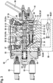
- Fig.3 shows a valve disc 50 with the pressure compensator arrangement 10 according to Fig.1 .
- the valve disk 50 comprises a linearly movable main slide 53, with which a fluid connection to the first and second working connection 51; 52 can be controlled.
- a fluid connection to the first and second working connection 51; 52 can be controlled.
- both the first and the second working connection 51; 52 are blocked.
- the first working connection 51 is fluidically connected to the output point 15, whereby the second working connection 52 is fluidically connected to a fluid return 58.
- the reference number 91a designates the control edge of the main orifice 91, which is assigned to the first working connection 51.
- the pressure at the first working connection 51 is reported to the first control point 11 by means of a load signaling channel system 59 in the main slide 53.
- the corresponding load signal is the subject of the DE 196 31 803 B4 , whereby other load reporting systems are also known which can also be used within the scope of the present invention.
- the second working connection 52 is fluidically connected to the output point 15, whereby the first working connection 51 is fluidically connected to a fluid return 58.
- the reference number 91b designates the control edge of the main orifice 91, which is assigned to the second working connection 52.
- the pressure at the second working connection 52 is reported to the first control point 11 by means of the load signaling channel system 59 in the main slide 53.
- valve disk 50 comprises two separate working fluid returns 58, which each connect all valve disks 50 of a valve block perpendicular to the plane of the drawing of the Fig.3 It is understood that the present invention can also be used with a monolithic valve block
- the working fluid returns 58 are preferably connected to a tank (No. 92 in Fig.1 ) of an open hydraulic circuit.
- the inlet point 14 is formed by a channel which connects all valve discs 50 of the valve block perpendicular to the plane of the Fig.3 , this channel preferably being connected to a pump which sucks pressurized fluid from said tank and delivers it under pressure to the inlet point 14.
- the pressurized fluid is preferably a liquid and most preferably hydraulic oil.
- the two pressure relief valves 57 limit the pressure at the respective associated working connection 51; 52.
- a screw plug can be screwed in so that the relevant bore, including the fluid connection to the fluid return 58, is sealed fluid-tight.
- the separate auxiliary assembly 90 is attached to the valve housing 16 of the valve disc 50, in particular by being screwed there.
- the control valve 80 is accommodated there, in particular, the auxiliary assembly 90 having the reference to Fig.1 explained fluid connections.
- a separate control fluid return 93 is used for the connection to the tank.
- the control fluid return 93 and the control fluid inlet 94 are each holes which connect all valve disks of the valve block perpendicular to the plane of the drawing of the Fig.3
- the control fluid return 93 is connected to the tank separately from the working fluid return 58, so that large fluid flows in the working fluid return 58 do not cause pressure fluctuations in the control fluid return 93.
- the control fluid inlet 94 is connected to the pump, for example, via an associated pressure regulator.
- the two pilot valves 55 are preferably fluidically connected to the control fluid return 93 and the control fluid inlet 94.
- the 2-way pressure regulator 70 can be optionally Fig.1 or the aperture assembly 70' to Fig. 2 be included.
Landscapes
- Engineering & Computer Science (AREA)
- Physics & Mathematics (AREA)
- Fluid Mechanics (AREA)
- Mechanical Engineering (AREA)
- General Engineering & Computer Science (AREA)
- Safety Valves (AREA)
Abstract
Description
- Die Erfindung betrifft eine Druckwaagenanordnung gemäß dem Oberbegriff von Anspruch 1.
- Aus der
DE 196 31 803 B4 ist eine Druckwaagenanordnung bekannt, deren Steuerschieber eine erste und eine zweite Blende bildet, die bei einer Bewegung des Steuerschiebers gemeinsam und gegenläufig verstellt werden. Mit der ersten Blende wird eine Ist-Druckdifferenz zwischen einer ersten Steuerstelle und einer Ausgangsstelle auf eine vorgegebene Soll-Druckdifferenz eingeregelt, welche durch die Vorspannung einer Regelfeder definiert ist. Die zweite Blende bewirkt eine Lasthaltung. Die erste und die zweite Blende sind fluidisch in Reihe geschaltet, wobei zwischen der ersten und der zweiten Blende eine dritte Steuerstelle angeordnet ist. Anzumerken ist, dass die zweite Blende in derDE 196 31 803 B4 nur in der Figur gezeigt, aber nicht im Text beschrieben ist. - Aus der
DE 10 2020 202 985 A1 ist eine Druckwaagenanordnung bekannt, die eine Flow-Boost-Funktion umfasst. Dabei wird die Druckwaage mittels eines zugeordneten Ventils so verstellt, dass die erste Blende maximal geöffnet ist. - Hinzuweisen ist noch auf die
DE 103 03 385 B4 , bei welcher Druckwaagen mit einer einzigen Blende mittels Schaltventilen beeinflusst werden. - Im Rahmen der vorliegenden Erfindung soll eine sogenannte Flow-Cut-Funktion realisiert werden, d.h. der Fluidstrom, welcher von der Eingangsstelle zum verbundenen Arbeitsanschluss fließt (Hauptstrom), soll absperrbar sein, und zwar unabhängig von der Stellung der Hauptblende bzw. des Hauptschiebers.
- Gemäß Anspruch 1 wird vorgeschlagen, dass ein Steuerventil mit einer geschlossenen und einer offenen Schaltstellung vorgesehen ist, wobei die zweite Steuerstelle über das Steuerventil in der offenen Schaltstellung mit einem Fluidrücklauf derart verbunden ist, dass die zweite Blende ganz geschlossen ist, gleich, welcher Druck an der Eingangsstelle anliegt. Um das gewünschte Ergebnis zu erreichen, können eine dritte Blende mit konstantem Strömungswiderstand und der Strömungswiderstand des Steuerventils in der geöffneten Schaltstellung in geeigneter Weise aufeinander abgestimmt sein. Es ist denkbar, dass der genannte Strömungswiderstand des Steuerventils erheblich kleiner gewählt wird als der Strömungswiderstand der dritten Blende, so dass sich an der ersten Steuerstelle im Wesentlichen der Druck im Fluidrücklauf einstellt. Diese besonders einfache Lösung hat jedoch den Nachteil, dass sehr viel Druckfluid zum Tank hin verloren gehen kann, wenn die Flow-Cut-Funktion aktiviert ist. Dieser Fluidverlust ist besonders groß, wenn die Schaltung zuverlässig funktionieren soll. Wie diesem Problem zu begegnen ist, wird weiter unten erläutert.
- Die Druckwaagenanordnung wird vorzugsweise mit einem Druckfluid verwendet, bei dem es sich höchst vorzugsweise um eine Flüssigkeit und insbesondere um Hydrauliköl handelt. Der Fluidrücklauf ist vorzugsweise mit einem Tank eines offenen hydraulischen Kreislaufs verbunden. Bei dem Fluidrücklauf kann es sich um einen Arbeitsfluidrücklauf handeln, an welchen auch die Aktuatoren (Zylinder, Hydromotore) des Hydrauliksystems angeschlossen sind. Es kann sich um einen gesonderten Steuerfluidrücklauf handeln, an welchen nur solche Hydraulikkomponenten angeschlossen sind, durch die ein kleiner Fluidstrom fließt, beispielsweise Vorsteuerventile. Zwischen die Ausgangsstelle und die erste Steuerstelle ist vorzugsweise zumindest eine stetig verstellbare Hauptblende geschaltet.
- In den abhängigen Ansprüchen sind vorteilhafte Weiterbildungen und Verbesserungen der Erfindung angegeben.
- Es kann vorgesehen sein, dass in der geschlossenen Schaltstellung des Steuerventils ein unmittelbarer Fluidaustausch zwischen der zweiten Steuerstelle und dem Fluidrücklauf unterbunden ist. Damit arbeitet die Druckwaagenanordnung in der geschlossenen Schaltstellung so, als wäre die Flow-Cut-Funktion nicht vorhanden. Insbesondere wird die Regelung des Druckabfalls an der Hauptblende nicht nachteilig beeinflusst.
- Es kann vorgesehen sein, dass die zweite Blende zwischen der dritten Steuerstelle und der Ausgangsstelle angeordnet ist. Damit kann bei geschlossener dritter Blende kein Druckfluid über die dritte Steuerstelle abfließen. Die Lasthaltung durch die zweite Blende ist somit zuverlässig gewährleistet.
- Es kann vorgesehen sein, dass die dritte Blende Bestandteil eines 2-Wege-Stromregelventils ist. Damit ist der Fluidstrom, welcher durch die dritte Blende fließt, definiert oder zumindest nach oben begrenzt, gleich, welcher Druck an der Eingangsstelle anliegt.
- Es kann vorgesehen sein, dass das 2-Wege-Stromregelventil eine Hilfsdruckwaage umfasst, welche der dritten Blende fluidisch in Reihe geschaltet ist, wobei die Hilfsdruckwaage von einer Hilfsfeder und vom Druck unmittelbar stromabwärts der dritten Blende in eine Öffnungsrichtung beaufschlagt ist, wobei sie vom Druck unmittelbar stromaufwärts der dritten Blende in eine Schließrichtung beaufschlagt ist. Dieses 2-Wege-Stromregelventil ist besonders einfach aufgebaut. Die Vorspannung der Hilfsfeder legt den Druckabfall an der dritten Blende fest oder begrenzt diesen zumindest nach oben. Damit hängt der Fluidstrom durch die dritte Blende im Wesentlichen allein von deren Strömungswiderstand ab.
- Es kann vorgesehen sein, dass das Steuerventil von einer Rückstellfeder in die geschlossene Stellung vorgespannt ist, wobei es von einem Betätigungsmagnet in die geöffnete Stellung bewegbar ist. Mit dieser Belegung der genannten Schaltstellungen braucht der Betätigungsmagnet nur dann bestromt zu werden, wenn die Flow-Cut-Funktion aktiv sein soll, also in seltenen Ausnahmefällen. Die Kraft des Betätigungsmagnetes wirkt vorzugsweise unmittelbar auf den Ventilschieber des Steuerventils, wobei kein Vorsteuerventil vorgesehen ist. Der Betätigungsmagnet umfasst vorzugsweise einen Elektromagnet mit einer elektrischen Spule.
- Es kann vorgesehen sein, dass das Steuerventil von einer Rückstellfeder in die offene Stellung vorgespannt ist, wobei es von einem Betätigungsmagnet in die geschlossene Stellung bewegbar ist. Hierdurch wird insbesondere erreicht, dass die Flow-Cut-Funktion bei Stromausfall aktiviert wird. Der an die Druckwaagenanordnung angeschlossene Aktuator wird damit nicht mehr hydraulisch angetrieben. Er kann sich allenfalls durch sein Eigengewicht oder durch äußere Lasten bewegen. Die Kraft des Betätigungsmagnetes wirkt vorzugsweise unmittelbar auf den Ventilschieber des Steuerventils, wobei kein Vorsteuerventil vorgesehen ist.
- Es kann vorgesehen sein, dass zumindest die dritte Blende und vorzugsweise das gesamte 2-Wege-Stromregelventil innerhalb des Steuerschiebers angeordnet ist. Hierbei ist anzumerken, dass über das 2-Wege-Stromregelventil nur sehr kleine Fluidströme fließen, wobei dessen Regelgenauigkeit nicht besonders hoch sein muss. Es kann daher problemlos ein sehr kleines 2-Wege-Stromregelventil verwendet werden.
- Es kann vorgesehen sein, dass das Steuerventil Bestandteil einer gesonderten Hilfsbaugruppe ist, welche fest mit einem gesonderten Ventilgehäuse verbunden, insbesondere verschraubt, ist, wobei der Steuerschieber im Ventilgehäuse angeordnet ist. Hierdurch ist es möglich, eine Ventilscheibe ohne Flow-Cut-Funktion mit geringem Aufwand in eine Ventilscheibe mit Flow-Cut-Funktion umzubauen. Hierdurch vereinfacht sich die serienmäßige Herstellung der entsprechenden Baugruppen, weil die Anzahl an Bauteilvarianten minimiert ist. Das Steuerventil ist vorzugsweise als Einbauventil, insbesondere als Einschraubventil, ausgeführt.
- Es versteht sich, dass die vorstehend genannten und die nachfolgend noch zu erläuternden Merkmale nicht nur in der jeweils angegebenen Kombination, sondern auch in anderen Kombinationen oder in Alleinstellung verwendbar sind, ohne den Rahmen der vorliegenden Erfindung zu verlassen.
- Die Erfindung wird im Folgenden anhand der beigefügten Zeichnungen näher erläutert. Es zeigt:
- Fig. 1
- einen hydraulischen Schaltplan einer erfindungsgemäßen Druckwaagenanordnung;
- Fig. 2
- eine Alternative für das 2-Wege-Stromregleventil in
Fig. 1 ; und - Fig. 3
- eine Ventilscheibe mit der Druckwaagenanordnung nach
Fig. 1 . -
Fig. 1 zeigt einen hydraulischen Schaltplan einer erfindungsgemäßen Druckwaagenanordnung 10. Mit der Druckwaagenanordnung 10 wird in erster Linie die Differenz zwischen dem Druck an der ersten Steuerstelle 11 und dem Druck an der Ausgangsstelle 15 (Ist-Druckdifferenz) auf einen konstanten Wert (Soll-Druckdifferenz) eingeregelt, welcher durch die Vorspannung der Regelfeder 23 bestimmt wird. Damit hängt die Bewegungsgeschwindigkeit des an den ersten und den zweiten Arbeitsanschluss angeschlossenen Aktuators allein von der Stellung des Hauptschiebers (Nr. 53 inFig. 2 ) ab und nicht von der am genannten Aktuator angreifenden Last. Dabei bildet der genannte Hauptschieber die Hauptblende 91, welche durch Bewegung des Hauptschiebers stetig verstellt wird. Bei dem inFig. 3 dargestellten Hauptschieber ist für die beiden Bewegungsrichtungen des Aktuators jeweils eine gesonderte Hauptblende (Nr. 91a; 91b inFig. 3 ) vorgesehen, die inFig. 1 zu einer Hauptblende 91 zusammengefasst sind. Die erste Steuerstelle 11 ist unmittelbar stromabwärts der Hauptblende 91 angeordnet, wobei die Ausgangsstelle 15 unmittelbar stromaufwärts der Hauptblende 91 angeordnet ist. Die oben erläuterte Ist-Druckdifferenz ist dementsprechend der Druckabfall an der Hauptblende 91. Die Stellgröße der oben erläuterten Regelung ist die Einstellung der stetig verstellbaren ersten Blende 21, welche vom beweglichen Steuerschieber 20 definiert wird. - Darüber hinaus bewirkt die Druckwaagenanordnung 10 eine Lasthaltung, d.h. es kann kein Druckfluid von der Ausgangsstelle 15 zur Eingangsstelle 14 fließen, insbesondere, wenn der Druck an der Eingangsstelle 14 nicht ausreicht, um die am genannten Aktuator angreifende Last zu halten. Die Lasthaltung wird mit der zweiten Blende 22 bewirkt.
- Die erste und die zweite Blende 21; 22 sind zwischen der Eingangsstelle 14 und der Ausgangsstelle 15 fluidisch in Reihe geschaltet, wobei die erste Blende 21 zwischen der Eingangsstelle 14 und der zweiten Blende 22 angeordnet ist.
- Die erste und die zweite Blende 21; 22 werden von einem linearbeweglichen Steuerschieber 20 gebildet, so dass sie bei einer Bewegung des Steuerschiebers 20 gemeinsam verstellt werden. In der ersten Endstellung 41 des Steuerschiebers 20, welche durch die Regelfeder 23 vorgespannt ist, ist die zweite Blende 22 ganz geschlossen, wobei die stetig verstellbare erste Blende 21 maximal weit offen ist. Wird der Steuerschieber 20 ausgehend von der ersten Endstellung 41 in Richtung der gegenüberliegenden zweiten Endstellung 42 bewegt, so sinkt der kombinierte Strömungswiderstand von erster und zweiter Blende 21; 22 zuerst vergleichsweise schnell, weil die zweite Blende 22 schnell öffnet. In einer Mittelstellung 43 ist der gemeinsame Strömungswiderstand von erster und zweiter Blende 21; 22 minimal.
- Wird der Steuerschieber 20 ausgehend von der Mittelstellung 43 weiter in Richtung der zweiten Endstellung 42 bewegt, so steigt der gemeinsame Strömungswiderstand von erster und zweiter Blende 21; 22 langsam an, weil die erste Blende 21 sanft und stetig schließt. In diesem Bereich findet die oben erläuterte Regelung der Druckdifferenz zwischen erster Steuerstelle 11 und Ausgangsstelle 15 statt. In diesem Bereich ist der Druck an der dritten Steuerstelle 13, welche zwischen der ersten und der zweiten Blende 21; 22 angeordnet ist, im Wesentlichen gleich dem Druck an der Ausgangsstelle 15. Dieser Druck wird über das 2-Wege-Stromregelventil 70 an die der Regelfeder 23 gegenüberliegenden Stirnseite des Steuerschiebers 20 geleitet, wobei der dortige Fluidraum die zweite Steuerstelle 12 bildet.
- Die Stirnseite des Steuerschiebers 20, auf welche die vorgespannte Regelfeder 23 wirkt, wird außerdem vom Druck der ersten Steuerstelle 11 beaufschlagt. Wenn die Ist-Druckdifferenz die Soll-Druckdifferenz (Vorspannung der Regelfeder) überschreitet, schließt die erste Blende 21, wodurch sich der Fluidstrom über die Hauptblende 91 verringert. In der Folge sinkt die Ist-Druckdifferenz. Im umgekehrten Fall öffnet die erste Blende 21, wodurch die Ist-Druckdifferenz ansteigt.
- Im Rahmen der Erfindung soll eine Möglichkeit geschaffen werden, den Fluidstrom von der Eingangsstelle 14 zum damit verbundenen Arbeitsanschluss (Nr. 51; 52 in
Fig. 3 ) zu sperren, und zwar unabhängig von der Einstellung der Hauptblende 91. Die Hauptblende 91 kann handbetätigt sein, wobei die Erfindung beispielsweise eine Absperrung im Notfall ermöglichen soll, die automatisch erfolgt, wenn der entsprechende Notfall erkannt wird. - Die genannte Absperrung wird bewirkt, indem der Steuerschieber 20 mittels des Steuerventils 80 in die geschlossene Stellung der zweiten Blende 22 bewegt wird. Das Steuerventil 80 hat eine geschlossene und eine offene Schaltstellung 81; 82. Die geschlossene Schaltstellung 81 ist vorliegend mittels einer Rückstellfeder 83 vorgespannt, wobei die offene Schaltstellung 82 mittels eines Betätigungsmagnetes 84 eingestellt werden kann. Wenn die Flow-Cut-Funktion insbesondere bei Stromausfall aktiv sein soll, sind die beiden Schaltstellungen 81; 82 vorzugsweise zu vertauschen. Mit der in
Fig. 1 gezeigten Belegung der beiden Schaltstellungen 81; 82 verhält sich die Druckwaagenanordnung 10 im stromlosen Zustand so wie eine Druckwaagenanordnung ohne Flow-Cut-Funktion. - In der geschlossenen Schaltstellung 81 führt die Druckwaagenanordnung 10 die oben erläuterte Regelung der Ist-Druckdifferenz an der Hauptblende 91 durch. Dementsprechend ist die Fluidverbindung zwischen der zweiten Steuerstelle 12 und dem Fluidrücklauf 96 zum Tank 92 hin gesperrt. Die entsprechende Regelung findet bei der Ausführungsform nach
Fig. 1 also nur statt, wenn der Betätigungsmagnet 84 nicht bestromt ist. - Wenn der Betätigungsmagnet 84 des Steuerventils 80 bestromt wird, wird die offene Schaltstellung 82 eingestellt. Ausgehend von der dritten Steuerstelle 13 kann Druckfluid über das 2-Wege-Stromregelventil 70, weiter über die zweite Steuerstelle 12, weiter über das Steuerventil 80, weiter über den Fluidrücklauf 96 zum Tank 92 fließen. An der zweiten Steuerstelle 12 stellt sich also ein Druck ein, der zwischen dem Druck der dritten Steuerstelle 13 und dem Druck im Tank 92 liegt. Damit die Flow-Cut-Funktion zuverlässig aktiviert wird bzw. damit die zweite Blende 82 ganz geschlossen ist, muss der Druck der ersten Steuerstelle 12 möglichst nah am Druck im Tank liegen, so dass die Regelfeder 23 die entsprechende Druckkraft überwinden kann.
- Kritisch sind an dieser Stelle Betriebszustände, in welchen an der Eingangsstelle 14 ein sehr hoher Druck anliegt. Dies kann vorkommen, wenn die Druckwaagenanordnung 10 Bestandteil eines Ventilblocks ist, mittels dem mehrere Aktuatoren von einer gemeinsamen Pumpe her mit Druckfluid versorgt werden. Der Förderdruck der Pumpe, welcher dem Druck an der Eingangsstelle 14 entspricht, wird dann vom lasthöchsten Aktuator bestimmt, wobei die erfindungsgemäße Druckwaagenanordnung einem anderen Aktuator zugeordnet sein kann. Würde man nun wie in
Fig. 2 dargestellt anstelle des 2-Wege-Stromregelventils 70 ausschließlich die feste dritte Blende 73 zwischen die dritte und die zweite Steuerstelle 13; 12 schalten, so könnte bei aktivierter Flow-Cut-Funktion ein großer Fluidstrom von der Eingangsstelle 14 über das Steuerventil 80 zum Tank 92 fließen. Man müsste das Steuerventil 80 sehr widerstandsarm und damit sehr groß auslegen, um den gewünschten niedrigen Druck an der zweiten Steuerstelle 12 zu erreichen. Dieser Fluidstrom wäre überdies mit erheblichen Energieverlusten verbunden. - Um diesem Problem abzuhelfen, ist die dritte Blende 73 Bestandteil eines 2-Wege-Stromregelventils 70. Der Fluidstrom über die dritte Blende 73 hängt damit im Wesentlichen nur noch von der Vorspannung der Hilfsfeder an der entsprechenden Hilfsdruckwaage ab, welcher der dritten Blende 73 fluidisch in Reihe geschaltet ist. Der genannte Fluidstrom ist im Wesentlichen unabhängig vom Druck an der Eingangsstelle 14. Das 2-Wege-Stromregelventil 70 kann sehr einfach und klein ausgeführt sein, da es nur kleine Fluidströme durchlassen soll, wobei es nur bei großen Drücken wirksam sein soll, um den Fluidstrom nach oben zu begrenzen. Für die Regelfunktion der Druckwaagenanordnung 10 kommt es allein darauf an, dass der genannte Fluidstrom ausreicht, um kleine Leckagen auszugleichen. In der Folge sind die Drücke an der zweiten und der dritten Steuerstelle 12; 13 im Wesentlichen gleich, wenn am Steuerventil 80 die geschlossene Stellung 81 eingestellt ist.
- Die Hilfsdruckwaage 71 des 2-Wege-Stromregelventils 70 ist der dritten Blende 73 fluidisch in Reihe geschaltet, wobei sie wie dargestellt stromaufwärts der dritten Blende 73 angeordnet sein kann. Die Hilfsdruckwaage 71 kann aber auch stromabwärts der dritten Blende 73 angeordnet sein. Unmittelbar stromaufwärts der dritten Blende 73 zur dritten Steuerstelle 14 hin ist eine vierte Steuerstelle 74 angeordnet. Unmittelbar stromabwärts der dritten Blende 73 ist die zweite Steuerstelle 12 angeordnet. Mit der Hilfsdruckwaage 71 wird die Druckdifferenz zwischen der vierten und der zweiten Steuerstelle 74; 12 auf den durch die Vorspannung der Hilfsfeder 72 vorgegebenen Wert eingeregelt. Der Druck an der vierten Steuerstelle 14 beaufschlagt die Hilfsdruckwaage 71 dementsprechend in Schließrichtung, wobei der Druck an der zweiten Steuerstelle 12 und die Vorspannkraft der Hilfsfeder 72 die Hilfsdruckwaage 71 in Öffnungsrichtung beaufschlagen.
- Hinzuweisen ist noch auf das Wechselventil 95, welches Bestandteil einer Wechselventilkaskade ist, mittels derer ein höchster Lastdruck aus mehreren individuellen Lastdrücken bestimmt wird. Der individuelle Lastdruck der erfindungsgemäßen Druckwaagenanordnung 10 ist der Druck an der ersten Steuerstelle 11. Mittels des höchsten Lastdrucks wird beispielsweise der Förderdruck der Pumpe geregelt, welche Druckfluid zur Eingangsstelle 14 fördert.
-
Fig. 2 zeigt eine Alternative für das 2-Wege-Stromregelventil inFig. 1 . Im Übrigen ist diese zweite Ausführungsform der Druckwaagenanordnung 10 unverändert gegenüber der Ausführungsform nachFig. 1 , so dass diesbezüglich auf die Ausführungen zuFig. 1 verwiesen wird. - Die Blendebaugruppe 70' ersetzt das 2-Wege-Stromregelventil nach
Fig. 1 , wobei die Blendenbaugruppe 70' allein die dritte Blende 73 umfasst. Die dritte Blende 73 hat vorzugsweise einen festen Strömungswiderstand. Die Blendenbaugruppe 70' umfasst vorzugsweise ein einziges Teil, welches an der inFig. 3 mit 70' markierten Stelle in den Steuerschieber (Nr. 20 inFig. 3 ) eingeschraubt ist. -
Fig. 3 zeigt eine Ventilscheibe 50 mit der Druckwaagenanordnung 10 nachFig. 1 . Die Ventilscheibe 50 umfasst einen linearbeweglichen Hauptschieber 53, mit dem eine Fluidverbindung zum ersten und zum zweiten Arbeitsanschluss 51; 52 steuerbar ist. In der inFig. 3 gezeigten Mittelstellung des Hauptschiebers 53, welche durch die Feder 54 vorgespannt ist, ist sowohl der erste als auch der zweite Arbeitsanschluss 51; 52 gesperrt. - Wird der Hauptschieber 53 ausgehend von der Mittelstellung mittels der Vorsteuerventile 55 oder mittels des Handhebels 56 nach rechts bewegt, so ist der erste Arbeitsanschluss 51 mit der Ausgangsstelle 15 fluidisch verbunden, wobei der zweite Arbeitsanschluss 52 mit einem Fluidrücklauf 58 fluidisch verbunden ist. Das Bezugszeichen 91a kennzeichnet die Steuerkante der Hauptblende 91, welche dem ersten Arbeitsanschluss 51 zugeordnet ist. Der Druck am ersten Arbeitsanschluss 51 wird mittels eines Lastmeldekanalsystems 59 im Hauptschieber 53 zur ersten Steuerstelle 11 hin gemeldet. Die entsprechende Lastmeldung ist Gegenstand der
DE 196 31 803 B4 , wobei auch andere Lastmeldesysteme bekannt sind, die im Rahmen der vorliegenden Erfindung ebenfalls verwendbar sind. - Wird der Hauptschieber 53 ausgehend von der Mittelstellung nach links bewegt, so ist der zweite Arbeitsanschluss 52 mit der Ausgangsstelle 15 fluidisch verbunden, wobei der erste Arbeitsanschluss 51 mit einem Fluidrücklauf 58 fluidisch verbunden ist. Das Bezugszeichen 91b kennzeichnet die Steuerkante der Hauptblende 91, welche dem zweiten Arbeitsanschluss 52 zugeordnet ist. Der Druck am zweiten Arbeitsanschluss 52 wird mittels des Lastmeldekanalsystems 59 im Hauptschieber 53 zur ersten Steuerstelle 11 hin gemeldet. Anzumerken ist, dass die vorliegende Ventilscheibe 50 zwei gesonderte Arbeitsfluidrückläufe 58 umfasst, welche jeweils alle Ventilscheiben 50 eines Ventilblocks senkrecht zur Zeichenebene der
Fig. 3 durchsetzen. Es versteht sich, dass die vorliegende Erfindung auch mit einem monolithischen Ventilblock verwendbar ist. Die Arbeitsfluidrückläufe 58 sind vorzugsweise an einen Tank (Nr. 92 inFig. 1 ) eines offenen hydraulischen Kreislaufs permanent fluidisch angeschlossen. - Die Eingangsstelle 14 wird von einem Kanal gebildet, welcher alle Ventilscheiben 50 des Ventilblocks senkrecht zur Zeichenebene der
Fig. 3 durchsetzt, wobei dieser Kanal vorzugsweise an eine Pumpe angeschlossen ist, welche Druckfluid aus dem genannten Tank ansaugt und unter Druck zur Eingangsstelle 14 fördert. Bei dem Druckfluid handelt es sich vorzugsweise um eine Flüssigkeit und höchst vorzugsweise um Hydrauliköl. - Mit den beiden Druckbegrenzungsventilen 57 wird der Druck am jeweils zugeordneten Arbeitsanschluss 51; 52 nach oben begrenzt. Anstelle eines Druckbegrenzungsventils 57 kann eine Verschlussschraube eingeschraubt sein, so dass die betreffende Bohrung einschließlich der Fluidverbindung zum Fluidrücklauf 58 hin fluiddicht verschlossen ist.
- Die gesonderte Hilfsbaugruppe 90 ist am Ventilgehäuse 16 der Ventilscheibe 50 befestigt, wobei sie insbesondere dort verschraubt ist. Dort ist insbesondere das Steuerventil 80 aufgenommen, wobei die Hilfsbaugruppe 90 die mit Bezug auf
Fig. 1 erläuterten Fluidverbindungen bereitstellt. Vorliegend wird für die Verbindung zum Tank hin ein gesonderter Steuerfluidrücklauf 93 benutzt. Beim Steuerfluidrücklauf 93 und beim Steuerfluidzulauf 94 handelt es sich jeweils um Bohrungen, welche alle Ventilscheiben des Ventilblocks senkrecht zur Zeichenebene derFig. 3 durchsetzen. Der Steuerfluidrücklauf 93 ist gesondert vom Arbeitsfluidrücklauf 58 an den Tank angeschlossen, so dass große Fluidströme im Arbeitsfluidrücklauf 58 keine Druckschwankungen im Steuerfluidrücklauf 93 verursachen. Der Steuerfluidzulauf 94 ist beispielsweise über einen zugeordneten Druckregler an die Pumpe angeschlossen. Die beiden Vorsteuerventile 55 sind vorzugsweise an den Steuerfluidrücklauf 93 und den Steuerfluidzulauf 94 fluidisch angeschlossen. - Hinzuweisen ist noch auf die stirnseitige Aufnahmeausnehmung 97 im Steuerschieber 20. Dort können wahlweise der 2-Wege-Druckregler 70 nach
Fig. 1 oder die Blendenbaugruppe 70' nachFig. 2 aufgenommen sein. -
- 10
- Druckwaagenanordnung
- 11
- erste Steuerstelle
- 12
- zweite Steuerstelle
- 13
- dritte Steuerstelle
- 14
- Eingangsstelle
- 15
- Ausgangsstelle
- 16
- Ventilgehäuse
- 20
- Steuerschieber
- 21
- erste Blende
- 22
- zweite Blende
- 23
- Regelfeder
- 24
- Anschlagfläche
- 41
- erste Endstellung
- 42
- zweite Endstellung
- 43
- Mittelstellung
- 50
- Ventilscheibe
- 51
- erster Arbeitsanschluss
- 52
- zweiter Arbeitsanschluss
- 53
- Hauptschieber
- 54
- Feder
- 55
- Vorsteuerventil
- 56
- Handhebel
- 57
- Druckbegrenzungsventil
- 58
- Arbeitsfluidrücklauf
- 59
- Lastmeldekanalsystem
- 60
- Gewindebohrung für Rückschlagventil
- 61
- erste Bohrung
- 62
- zweite Bohrung
- 63
- Verschlussschraube
- 64
- Durchgangsbohrung
- 65
- Innensechskant
- 66
- Schraubenkopf
- 70
- 2-Wege-Stromregelventil
- 70'
- Blendenbaugruppe
- 71
- Hilfsdruckwaage
- 72
- Hilfsfeder
- 73
- dritte Blende
- 74
- vierte Steuerstelle
- 80
- Steuerventil
- 81
- geschlossene Schaltstellung
- 82
- offene Schaltstellung
- 83
- Rückstellfeder
- 84
- Betätigungsmagnet
- 90
- Hilfsbaugruppe
- 91
- Hauptblende
- 91a
- Steuerkante der Hauptblende, welche dem ersten Arbeitsanschluss zugeordnet ist
- 91b
- Steuerkante der Hauptblende, welche dem zweiten Arbeitsanschluss zugeordnet ist
- 92
- Tank
- 93
- Steuerfluidrücklauf
- 94
- Steuerfluidzulauf
- 95
- Wechselventil
- 96
- Fluidrücklauf
- 97
- Aufnahmeausnehmung
Claims (9)
- Druckwaagenanordnung (10) mit einem linearbeweglichen Steuerschieber (20), welcher eine erste und eine zweite Blende (21; 22) definiert, die durch Bewegung des Steuerschiebers (20) gemeinsam verstellbar ist, wobei sie fluidisch zwischen eine Eingangsstelle (14) und eine Ausgangsstelle (15) in Reihe geschaltet sind, wobei die erste Blende (21) in einer ersten Endstellung (41) des Steuerschiebers (20) ganz geöffnet ist, wobei die zweite Blende (22) in der ersten Endstellung (41) ganz geschlossen ist, wobei die erste Blende (21) in einer der ersten Endstellung (21) gegenüberliegenden zweiten Endstellung (22) des Steuerschiebers (20) ganz geschlossen ist, wobei ihr Öffnungsquerschnitt von der ersten zur zweiten Endstellung (21; 22) hin stetig abnimmt, wobei die zweite Blende (22) in der zweiten Endstellung (42) ganz geöffnet ist, wobei der Steuerschieber (20) von einer Regelfeder (23) und einem Druck an einer ersten Steuerstelle (11) in Richtung der ersten Endstellung (41) beaufschlagt ist, wobei er von einem Druck an einer zweiten Steuerstelle (12) in Richtung der zweiten Endstellung (42) beaufschlagt ist, wobei eine dritte Steuerstelle (13) unmittelbar stromabwärts der ersten Blende (21) zur Ausgangsstelle (15) hin angeordnet ist, wobei die dritte Steuerstelle (13) über zumindest eine dritte Blende (73) mit der zweiten Steuerstelle (12) fluidisch verbunden ist,
dadurch gekennzeichnet, dass ein Steuerventil (80) mit einer geschlossenen und einer offenen Schaltstellung (81; 82) vorgesehen ist, wobei die zweite Steuerstelle (12) über das Steuerventil in der offenen Schaltstellung (82) mit einem Fluidrücklauf (96) derart verbunden ist, dass die zweite Blende (22) ganz geschlossen ist, gleich, welcher Druck an der Eingangsstelle (14) anliegt. - Druckwaagenanordnung (10) nach Anspruch 1,
wobei in der geschlossenen Schaltstellung (81) des Steuerventils (80) ein unmittelbarer Fluidaustausch zwischen der zweiten Steuerstelle (12) und dem Fluidrücklauf (96) unterbunden ist. - Druckwaagenanordnung (10) nach einem der vorstehenden Ansprüche,
wobei die zweite Blende (22) zwischen der dritten Steuerstelle (13) und der Ausgangsstelle (15) angeordnet ist. - Druckwaagenanordnung (10) nach einem der vorstehenden Ansprüche,
wobei die dritte Blende (73) Bestandteil eines 2-Wege-Stromregelventils (70) ist. - Druckwaagenanordnung (10) nach Anspruch 4,
wobei das 2-Wege-Stromregelventil (70) eine Hilfsdruckwaage (71) umfasst, welche der dritten Blende (73) fluidisch in Reihe geschaltet ist, wobei die Hilfsdruckwaage (71) von einer Hilfsfeder (72) und vom Druck unmittelbar stromabwärts der dritten Blende (73) in eine Öffnungsrichtung beaufschlagt ist, wobei sie vom Druck unmittelbar stromaufwärts der dritten Blende (73) in eine Schließrichtung beaufschlagt ist. - Druckwaagenanordnung (10) nach einem der vorstehenden Ansprüche,
wobei das Steuerventil (80) von einer Rückstellfeder in die geschlossene Stellung (81) vorgespannt ist, wobei es von einem Betätigungsmagnet (84) in die geöffnete Stellung (82) bewegbar ist. - Druckwaagenanordnung (10) nach einem der Ansprüche 1 bis 5,
wobei das Steuerventil (80) von einer Rückstellfeder in die offene Stellung (82) vorgespannt ist, wobei es von einem Betätigungsmagnet (84) in die geschlossene Stellung (81) bewegbar ist. - Druckwaagenanordnung (10) nach einem der vorstehenden Ansprüche,
wobei zumindest die dritte Blende (73) und vorzugsweise das gesamte 2-Wege-Stromregelventil (70) innerhalb des Steuerschiebers (20) angeordnet ist. - Druckwaagenanordnung (10) nach einem der vorstehenden Ansprüche,
wobei das Steuerventil (80) Bestandteil einer gesonderten Hilfsbaugruppe (90) ist, welche fest mit einem gesonderten Ventilgehäuse (16) verbunden, insbesondere verschraubt, ist, wobei der Steuerschieber (20) im Ventilgehäuse (16) angeordnet ist.
Applications Claiming Priority (1)
| Application Number | Priority Date | Filing Date | Title |
|---|---|---|---|
| DE102023200946.3A DE102023200946A1 (de) | 2023-02-06 | 2023-02-06 | Druckwaagenanordnung mit schaltbarer Flow-Cut-Funktion |
Publications (2)
| Publication Number | Publication Date |
|---|---|
| EP4411148A1 true EP4411148A1 (de) | 2024-08-07 |
| EP4411148B1 EP4411148B1 (de) | 2025-08-20 |
Family
ID=89707650
Family Applications (1)
| Application Number | Title | Priority Date | Filing Date |
|---|---|---|---|
| EP24153296.9A Active EP4411148B1 (de) | 2023-02-06 | 2024-01-23 | Druckwaagenanordnung mit schaltbarer flow-cut-funktion |
Country Status (3)
| Country | Link |
|---|---|
| EP (1) | EP4411148B1 (de) |
| DE (1) | DE102023200946A1 (de) |
| DK (1) | DK4411148T3 (de) |
Citations (4)
| Publication number | Priority date | Publication date | Assignee | Title |
|---|---|---|---|---|
| DE19631803B4 (de) | 1996-08-07 | 2007-08-02 | Bosch Rexroth Aktiengesellschaft | Hydraulische Steuervorrichtung |
| DE10303385B4 (de) | 2003-01-29 | 2018-11-29 | Buchholz Hydraulik Gmbh | Steuereinrichtung für eine Hub- und Senksteuerung |
| DE102018204642A1 (de) * | 2018-03-27 | 2019-10-02 | Robert Bosch Gmbh | Ventilbaugruppe mit Lasthaltung im Steuerschieber |
| DE102020202985A1 (de) | 2020-03-10 | 2021-09-16 | Robert Bosch Gesellschaft mit beschränkter Haftung | Hydraulische Steueranordnung mit entlastbarer Druckwaage und Druckwaage |
-
2023
- 2023-02-06 DE DE102023200946.3A patent/DE102023200946A1/de active Pending
-
2024
- 2024-01-23 EP EP24153296.9A patent/EP4411148B1/de active Active
- 2024-01-23 DK DK24153296.9T patent/DK4411148T3/da active
Patent Citations (4)
| Publication number | Priority date | Publication date | Assignee | Title |
|---|---|---|---|---|
| DE19631803B4 (de) | 1996-08-07 | 2007-08-02 | Bosch Rexroth Aktiengesellschaft | Hydraulische Steuervorrichtung |
| DE10303385B4 (de) | 2003-01-29 | 2018-11-29 | Buchholz Hydraulik Gmbh | Steuereinrichtung für eine Hub- und Senksteuerung |
| DE102018204642A1 (de) * | 2018-03-27 | 2019-10-02 | Robert Bosch Gmbh | Ventilbaugruppe mit Lasthaltung im Steuerschieber |
| DE102020202985A1 (de) | 2020-03-10 | 2021-09-16 | Robert Bosch Gesellschaft mit beschränkter Haftung | Hydraulische Steueranordnung mit entlastbarer Druckwaage und Druckwaage |
Also Published As
| Publication number | Publication date |
|---|---|
| DK4411148T3 (da) | 2025-10-27 |
| EP4411148B1 (de) | 2025-08-20 |
| DE102023200946A1 (de) | 2024-08-08 |
Similar Documents
| Publication | Publication Date | Title |
|---|---|---|
| EP0620371B1 (de) | Hydrauliksystem zur Versorgung offener oder geschlossener Hydraulikfunktionen | |
| DE102011104530A1 (de) | Hydraulische Stellanordnung | |
| DE1921977B2 (de) | Ventileinrichtung zur Steuerung der Druckmittelwege eines doppelwirkenden Servomotors | |
| DE102018003728A1 (de) | Ventilanordnung zur Druckmittelversorgung eines hydraulischen Verbrauchers | |
| EP1598560B1 (de) | Hydraulische Ventilanordnung | |
| EP2669528A2 (de) | Hydrostatische Ventilanordnung und hydrostatische Steueranordnung mit der Ventilanordnung | |
| DE102007030882A1 (de) | Hydraulische Steuerölversorgung | |
| WO2001038720A1 (de) | Ventil zum steuern von flüssigkeiten | |
| EP4411148B1 (de) | Druckwaagenanordnung mit schaltbarer flow-cut-funktion | |
| EP2891805A2 (de) | Steueranordnung und Steuerventil für eine derartige Steueranordnung | |
| DE3925297A1 (de) | Steuereinrichtung fuer eine verstellbare hydrostatische maschine | |
| DE112008003999T5 (de) | Fluidbetriebenes Betätigungssystem | |
| DE102009035278A1 (de) | Druckverstärker und zugehöriges Steuerventil | |
| DE4244304A1 (de) | Betätigungsvorrichtung für einen hydraulischen Stellantrieb mit druckproportionalem Stellsignal | |
| WO2003087585A1 (de) | Hydraulische steueranordnung in load-sensing technik | |
| DE102012220445A1 (de) | Hydraulische Steuereinrichtung für einen Antrieb mit mehreren hydraulischen Aktoren | |
| DE102022208306A1 (de) | Druckwaagenanordnung mit Flow-Cut-Funktion | |
| DE102022201755A1 (de) | Steuerschieber mit definiert gebrochener Kreisringkante | |
| EP1369596B1 (de) | Hydraulische Ventilanordnung | |
| WO2021063825A1 (de) | Hydrostatische schnellschaltsteuerung | |
| DE102017130485B4 (de) | Hydraulische Schaltungsanordnung zum Heben und Senken einer Last | |
| DE102021207837A1 (de) | Verfahren zum Betrieb einer Hydromaschine mit Kompensation einer Strömungskraft am Steuerschieber | |
| DE102012218271A1 (de) | Hydraulische Steuerung für reversierbare hydraulische Verbraucher | |
| DE102022208305A1 (de) | Druckwaagenanordnung mit Lasthaltung und Flow-Boost | |
| DE102024206922A1 (de) | Ventilanordnung für doppeltwirkendes Hubwerk |
Legal Events
| Date | Code | Title | Description |
|---|---|---|---|
| PUAI | Public reference made under article 153(3) epc to a published international application that has entered the european phase |
Free format text: ORIGINAL CODE: 0009012 |
|
| STAA | Information on the status of an ep patent application or granted ep patent |
Free format text: STATUS: THE APPLICATION HAS BEEN PUBLISHED |
|
| AK | Designated contracting states |
Kind code of ref document: A1 Designated state(s): AL AT BE BG CH CY CZ DE DK EE ES FI FR GB GR HR HU IE IS IT LI LT LU LV MC ME MK MT NL NO PL PT RO RS SE SI SK SM TR |
|
| STAA | Information on the status of an ep patent application or granted ep patent |
Free format text: STATUS: REQUEST FOR EXAMINATION WAS MADE |
|
| 17P | Request for examination filed |
Effective date: 20250207 |
|
| GRAP | Despatch of communication of intention to grant a patent |
Free format text: ORIGINAL CODE: EPIDOSNIGR1 |
|
| STAA | Information on the status of an ep patent application or granted ep patent |
Free format text: STATUS: GRANT OF PATENT IS INTENDED |
|
| RIC1 | Information provided on ipc code assigned before grant |
Ipc: F15B 20/00 20060101ALN20250526BHEP Ipc: F15B 13/01 20060101ALN20250526BHEP Ipc: F15B 13/04 20060101ALI20250526BHEP Ipc: F15B 13/02 20060101ALI20250526BHEP Ipc: F15B 11/16 20060101AFI20250526BHEP |
|
| GRAS | Grant fee paid |
Free format text: ORIGINAL CODE: EPIDOSNIGR3 |
|
| INTG | Intention to grant announced |
Effective date: 20250613 |
|
| GRAA | (expected) grant |
Free format text: ORIGINAL CODE: 0009210 |
|
| STAA | Information on the status of an ep patent application or granted ep patent |
Free format text: STATUS: THE PATENT HAS BEEN GRANTED |
|
| AK | Designated contracting states |
Kind code of ref document: B1 Designated state(s): AL AT BE BG CH CY CZ DE DK EE ES FI FR GB GR HR HU IE IS IT LI LT LU LV MC ME MK MT NL NO PL PT RO RS SE SI SK SM TR |
|
| REG | Reference to a national code |
Ref country code: GB Ref legal event code: FG4D Free format text: NOT ENGLISH |
|
| REG | Reference to a national code |
Ref country code: CH Ref legal event code: EP |
|
| REG | Reference to a national code |
Ref country code: IE Ref legal event code: FG4D Free format text: LANGUAGE OF EP DOCUMENT: GERMAN |
|
| REG | Reference to a national code |
Ref country code: DE Ref legal event code: R096 Ref document number: 502024000165 Country of ref document: DE |
|
| REG | Reference to a national code |
Ref country code: DK Ref legal event code: T3 Effective date: 20251024 |
|
| REG | Reference to a national code |
Ref country code: NL Ref legal event code: MP Effective date: 20250820 |
|
| PG25 | Lapsed in a contracting state [announced via postgrant information from national office to epo] |
Ref country code: IS Free format text: LAPSE BECAUSE OF FAILURE TO SUBMIT A TRANSLATION OF THE DESCRIPTION OR TO PAY THE FEE WITHIN THE PRESCRIBED TIME-LIMIT Effective date: 20251220 |
|
| PG25 | Lapsed in a contracting state [announced via postgrant information from national office to epo] |
Ref country code: NO Free format text: LAPSE BECAUSE OF FAILURE TO SUBMIT A TRANSLATION OF THE DESCRIPTION OR TO PAY THE FEE WITHIN THE PRESCRIBED TIME-LIMIT Effective date: 20251120 |
|
| REG | Reference to a national code |
Ref country code: LT Ref legal event code: MG9D |
|
| PG25 | Lapsed in a contracting state [announced via postgrant information from national office to epo] |
Ref country code: PT Free format text: LAPSE BECAUSE OF FAILURE TO SUBMIT A TRANSLATION OF THE DESCRIPTION OR TO PAY THE FEE WITHIN THE PRESCRIBED TIME-LIMIT Effective date: 20251222 |
|
| PG25 | Lapsed in a contracting state [announced via postgrant information from national office to epo] |
Ref country code: FI Free format text: LAPSE BECAUSE OF FAILURE TO SUBMIT A TRANSLATION OF THE DESCRIPTION OR TO PAY THE FEE WITHIN THE PRESCRIBED TIME-LIMIT Effective date: 20250820 |
|
| PG25 | Lapsed in a contracting state [announced via postgrant information from national office to epo] |
Ref country code: HR Free format text: LAPSE BECAUSE OF FAILURE TO SUBMIT A TRANSLATION OF THE DESCRIPTION OR TO PAY THE FEE WITHIN THE PRESCRIBED TIME-LIMIT Effective date: 20250820 Ref country code: NL Free format text: LAPSE BECAUSE OF FAILURE TO SUBMIT A TRANSLATION OF THE DESCRIPTION OR TO PAY THE FEE WITHIN THE PRESCRIBED TIME-LIMIT Effective date: 20250820 |
|
| PG25 | Lapsed in a contracting state [announced via postgrant information from national office to epo] |
Ref country code: GR Free format text: LAPSE BECAUSE OF FAILURE TO SUBMIT A TRANSLATION OF THE DESCRIPTION OR TO PAY THE FEE WITHIN THE PRESCRIBED TIME-LIMIT Effective date: 20251121 |
|
| PG25 | Lapsed in a contracting state [announced via postgrant information from national office to epo] |
Ref country code: SE Free format text: LAPSE BECAUSE OF FAILURE TO SUBMIT A TRANSLATION OF THE DESCRIPTION OR TO PAY THE FEE WITHIN THE PRESCRIBED TIME-LIMIT Effective date: 20250820 |
|
| PG25 | Lapsed in a contracting state [announced via postgrant information from national office to epo] |
Ref country code: LV Free format text: LAPSE BECAUSE OF FAILURE TO SUBMIT A TRANSLATION OF THE DESCRIPTION OR TO PAY THE FEE WITHIN THE PRESCRIBED TIME-LIMIT Effective date: 20250820 |
|
| PG25 | Lapsed in a contracting state [announced via postgrant information from national office to epo] |
Ref country code: PL Free format text: LAPSE BECAUSE OF FAILURE TO SUBMIT A TRANSLATION OF THE DESCRIPTION OR TO PAY THE FEE WITHIN THE PRESCRIBED TIME-LIMIT Effective date: 20250820 Ref country code: BG Free format text: LAPSE BECAUSE OF FAILURE TO SUBMIT A TRANSLATION OF THE DESCRIPTION OR TO PAY THE FEE WITHIN THE PRESCRIBED TIME-LIMIT Effective date: 20250820 |
|
| PG25 | Lapsed in a contracting state [announced via postgrant information from national office to epo] |
Ref country code: RS Free format text: LAPSE BECAUSE OF FAILURE TO SUBMIT A TRANSLATION OF THE DESCRIPTION OR TO PAY THE FEE WITHIN THE PRESCRIBED TIME-LIMIT Effective date: 20251120 |
|
| PG25 | Lapsed in a contracting state [announced via postgrant information from national office to epo] |
Ref country code: ES Free format text: LAPSE BECAUSE OF FAILURE TO SUBMIT A TRANSLATION OF THE DESCRIPTION OR TO PAY THE FEE WITHIN THE PRESCRIBED TIME-LIMIT Effective date: 20250820 |
|
| PG25 | Lapsed in a contracting state [announced via postgrant information from national office to epo] |
Ref country code: SM Free format text: LAPSE BECAUSE OF FAILURE TO SUBMIT A TRANSLATION OF THE DESCRIPTION OR TO PAY THE FEE WITHIN THE PRESCRIBED TIME-LIMIT Effective date: 20250820 |
|
| PGFP | Annual fee paid to national office [announced via postgrant information from national office to epo] |
Ref country code: DK Payment date: 20260121 Year of fee payment: 3 Ref country code: DE Payment date: 20260319 Year of fee payment: 3 |
|
| PGFP | Annual fee paid to national office [announced via postgrant information from national office to epo] |
Ref country code: AT Payment date: 20260301 Year of fee payment: 3 |
|
| PGFP | Annual fee paid to national office [announced via postgrant information from national office to epo] |
Ref country code: IT Payment date: 20260131 Year of fee payment: 3 |
|
| PG25 | Lapsed in a contracting state [announced via postgrant information from national office to epo] |
Ref country code: CZ Free format text: LAPSE BECAUSE OF FAILURE TO SUBMIT A TRANSLATION OF THE DESCRIPTION OR TO PAY THE FEE WITHIN THE PRESCRIBED TIME-LIMIT Effective date: 20250820 |
|
| PG25 | Lapsed in a contracting state [announced via postgrant information from national office to epo] |
Ref country code: EE Free format text: LAPSE BECAUSE OF FAILURE TO SUBMIT A TRANSLATION OF THE DESCRIPTION OR TO PAY THE FEE WITHIN THE PRESCRIBED TIME-LIMIT Effective date: 20250820 Ref country code: SK Free format text: LAPSE BECAUSE OF FAILURE TO SUBMIT A TRANSLATION OF THE DESCRIPTION OR TO PAY THE FEE WITHIN THE PRESCRIBED TIME-LIMIT Effective date: 20250820 |