EP4411033A1 - Schneckenextruder sowie kombinierte faserspinn-, streck- und wickelmaschine für die polymilchsäureindustrie - Google Patents
Schneckenextruder sowie kombinierte faserspinn-, streck- und wickelmaschine für die polymilchsäureindustrie Download PDFInfo
- Publication number
- EP4411033A1 EP4411033A1 EP22875101.2A EP22875101A EP4411033A1 EP 4411033 A1 EP4411033 A1 EP 4411033A1 EP 22875101 A EP22875101 A EP 22875101A EP 4411033 A1 EP4411033 A1 EP 4411033A1
- Authority
- EP
- European Patent Office
- Prior art keywords
- threaded sleeve
- screw extruder
- disposed
- compression section
- section
- Prior art date
- Legal status (The legal status is an assumption and is not a legal conclusion. Google has not performed a legal analysis and makes no representation as to the accuracy of the status listed.)
- Pending
Links
Images


Classifications
-
- B—PERFORMING OPERATIONS; TRANSPORTING
- B29—WORKING OF PLASTICS; WORKING OF SUBSTANCES IN A PLASTIC STATE IN GENERAL
- B29B—PREPARATION OR PRETREATMENT OF THE MATERIAL TO BE SHAPED; MAKING GRANULES OR PREFORMS; RECOVERY OF PLASTICS OR OTHER CONSTITUENTS OF WASTE MATERIAL CONTAINING PLASTICS
- B29B7/00—Mixing; Kneading
- B29B7/80—Component parts, details or accessories; Auxiliary operations
- B29B7/801—Valves
-
- B—PERFORMING OPERATIONS; TRANSPORTING
- B29—WORKING OF PLASTICS; WORKING OF SUBSTANCES IN A PLASTIC STATE IN GENERAL
- B29B—PREPARATION OR PRETREATMENT OF THE MATERIAL TO BE SHAPED; MAKING GRANULES OR PREFORMS; RECOVERY OF PLASTICS OR OTHER CONSTITUENTS OF WASTE MATERIAL CONTAINING PLASTICS
- B29B7/00—Mixing; Kneading
- B29B7/80—Component parts, details or accessories; Auxiliary operations
- B29B7/84—Venting or degassing ; Removing liquids, e.g. by evaporating components
- B29B7/845—Venting, degassing or removing evaporated components in devices with rotary stirrers
- B29B7/847—Removing of gaseous components before or after mixing
-
- B—PERFORMING OPERATIONS; TRANSPORTING
- B29—WORKING OF PLASTICS; WORKING OF SUBSTANCES IN A PLASTIC STATE IN GENERAL
- B29C—SHAPING OR JOINING OF PLASTICS; SHAPING OF MATERIAL IN A PLASTIC STATE, NOT OTHERWISE PROVIDED FOR; AFTER-TREATMENT OF THE SHAPED PRODUCTS, e.g. REPAIRING
- B29C48/00—Extrusion moulding, i.e. expressing the moulding material through a die or nozzle which imparts the desired form; Apparatus therefor
- B29C48/022—Extrusion moulding, i.e. expressing the moulding material through a die or nozzle which imparts the desired form; Apparatus therefor characterised by the choice of material
-
- B—PERFORMING OPERATIONS; TRANSPORTING
- B29—WORKING OF PLASTICS; WORKING OF SUBSTANCES IN A PLASTIC STATE IN GENERAL
- B29C—SHAPING OR JOINING OF PLASTICS; SHAPING OF MATERIAL IN A PLASTIC STATE, NOT OTHERWISE PROVIDED FOR; AFTER-TREATMENT OF THE SHAPED PRODUCTS, e.g. REPAIRING
- B29C48/00—Extrusion moulding, i.e. expressing the moulding material through a die or nozzle which imparts the desired form; Apparatus therefor
- B29C48/03—Extrusion moulding, i.e. expressing the moulding material through a die or nozzle which imparts the desired form; Apparatus therefor characterised by the shape of the extruded material at extrusion
- B29C48/05—Filamentary, e.g. strands
-
- B—PERFORMING OPERATIONS; TRANSPORTING
- B29—WORKING OF PLASTICS; WORKING OF SUBSTANCES IN A PLASTIC STATE IN GENERAL
- B29C—SHAPING OR JOINING OF PLASTICS; SHAPING OF MATERIAL IN A PLASTIC STATE, NOT OTHERWISE PROVIDED FOR; AFTER-TREATMENT OF THE SHAPED PRODUCTS, e.g. REPAIRING
- B29C48/00—Extrusion moulding, i.e. expressing the moulding material through a die or nozzle which imparts the desired form; Apparatus therefor
- B29C48/25—Component parts, details or accessories; Auxiliary operations
- B29C48/36—Means for plasticising or homogenising the moulding material or forcing it through the nozzle or die
- B29C48/50—Details of extruders
- B29C48/505—Screws
- B29C48/53—Screws having a varying channel depth, e.g. varying the diameter of the longitudinal screw trunk
-
- B—PERFORMING OPERATIONS; TRANSPORTING
- B29—WORKING OF PLASTICS; WORKING OF SUBSTANCES IN A PLASTIC STATE IN GENERAL
- B29C—SHAPING OR JOINING OF PLASTICS; SHAPING OF MATERIAL IN A PLASTIC STATE, NOT OTHERWISE PROVIDED FOR; AFTER-TREATMENT OF THE SHAPED PRODUCTS, e.g. REPAIRING
- B29C48/00—Extrusion moulding, i.e. expressing the moulding material through a die or nozzle which imparts the desired form; Apparatus therefor
- B29C48/25—Component parts, details or accessories; Auxiliary operations
- B29C48/36—Means for plasticising or homogenising the moulding material or forcing it through the nozzle or die
- B29C48/50—Details of extruders
- B29C48/68—Barrels or cylinders
- B29C48/685—Barrels or cylinders characterised by their inner surfaces, e.g. having grooves, projections or threads
- B29C48/688—Barrels or cylinders characterised by their inner surfaces, e.g. having grooves, projections or threads having threads
-
- B—PERFORMING OPERATIONS; TRANSPORTING
- B29—WORKING OF PLASTICS; WORKING OF SUBSTANCES IN A PLASTIC STATE IN GENERAL
- B29C—SHAPING OR JOINING OF PLASTICS; SHAPING OF MATERIAL IN A PLASTIC STATE, NOT OTHERWISE PROVIDED FOR; AFTER-TREATMENT OF THE SHAPED PRODUCTS, e.g. REPAIRING
- B29C48/00—Extrusion moulding, i.e. expressing the moulding material through a die or nozzle which imparts the desired form; Apparatus therefor
- B29C48/25—Component parts, details or accessories; Auxiliary operations
- B29C48/36—Means for plasticising or homogenising the moulding material or forcing it through the nozzle or die
- B29C48/50—Details of extruders
- B29C48/76—Venting, drying means; Degassing means
- B29C48/765—Venting, drying means; Degassing means in the extruder apparatus
- B29C48/766—Venting, drying means; Degassing means in the extruder apparatus in screw extruders
- B29C48/767—Venting, drying means; Degassing means in the extruder apparatus in screw extruders through a degassing opening of a barrel
-
- D—TEXTILES; PAPER
- D01—NATURAL OR MAN-MADE THREADS OR FIBRES; SPINNING
- D01D—MECHANICAL METHODS OR APPARATUS IN THE MANUFACTURE OF ARTIFICIAL FILAMENTS, THREADS, FIBRES, BRISTLES OR RIBBONS
- D01D1/00—Treatment of filament-forming or like material
- D01D1/04—Melting filament-forming substances
-
- D—TEXTILES; PAPER
- D01—NATURAL OR MAN-MADE THREADS OR FIBRES; SPINNING
- D01D—MECHANICAL METHODS OR APPARATUS IN THE MANUFACTURE OF ARTIFICIAL FILAMENTS, THREADS, FIBRES, BRISTLES OR RIBBONS
- D01D1/00—Treatment of filament-forming or like material
- D01D1/06—Feeding liquid to the spinning head
- D01D1/09—Control of pressure, temperature or feeding rate
-
- D—TEXTILES; PAPER
- D01—NATURAL OR MAN-MADE THREADS OR FIBRES; SPINNING
- D01F—CHEMICAL FEATURES IN THE MANUFACTURE OF ARTIFICIAL FILAMENTS, THREADS, FIBRES, BRISTLES OR RIBBONS; APPARATUS SPECIALLY ADAPTED FOR THE MANUFACTURE OF CARBON FILAMENTS
- D01F6/00—Monocomponent artificial filaments or the like of synthetic polymers; Manufacture thereof
- D01F6/58—Monocomponent artificial filaments or the like of synthetic polymers; Manufacture thereof from homopolycondensation products
- D01F6/62—Monocomponent artificial filaments or the like of synthetic polymers; Manufacture thereof from homopolycondensation products from polyesters
- D01F6/625—Monocomponent artificial filaments or the like of synthetic polymers; Manufacture thereof from homopolycondensation products from polyesters derived from hydroxy-carboxylic acids, e.g. lactones
-
- B—PERFORMING OPERATIONS; TRANSPORTING
- B29—WORKING OF PLASTICS; WORKING OF SUBSTANCES IN A PLASTIC STATE IN GENERAL
- B29C—SHAPING OR JOINING OF PLASTICS; SHAPING OF MATERIAL IN A PLASTIC STATE, NOT OTHERWISE PROVIDED FOR; AFTER-TREATMENT OF THE SHAPED PRODUCTS, e.g. REPAIRING
- B29C2948/00—Indexing scheme relating to extrusion moulding
- B29C2948/92—Measuring, controlling or regulating
- B29C2948/92009—Measured parameter
- B29C2948/92019—Pressure
-
- B—PERFORMING OPERATIONS; TRANSPORTING
- B29—WORKING OF PLASTICS; WORKING OF SUBSTANCES IN A PLASTIC STATE IN GENERAL
- B29C—SHAPING OR JOINING OF PLASTICS; SHAPING OF MATERIAL IN A PLASTIC STATE, NOT OTHERWISE PROVIDED FOR; AFTER-TREATMENT OF THE SHAPED PRODUCTS, e.g. REPAIRING
- B29C2948/00—Indexing scheme relating to extrusion moulding
- B29C2948/92—Measuring, controlling or regulating
- B29C2948/92504—Controlled parameter
- B29C2948/92514—Pressure
-
- B—PERFORMING OPERATIONS; TRANSPORTING
- B29—WORKING OF PLASTICS; WORKING OF SUBSTANCES IN A PLASTIC STATE IN GENERAL
- B29C—SHAPING OR JOINING OF PLASTICS; SHAPING OF MATERIAL IN A PLASTIC STATE, NOT OTHERWISE PROVIDED FOR; AFTER-TREATMENT OF THE SHAPED PRODUCTS, e.g. REPAIRING
- B29C48/00—Extrusion moulding, i.e. expressing the moulding material through a die or nozzle which imparts the desired form; Apparatus therefor
- B29C48/25—Component parts, details or accessories; Auxiliary operations
- B29C48/36—Means for plasticising or homogenising the moulding material or forcing it through the nozzle or die
- B29C48/395—Means for plasticising or homogenising the moulding material or forcing it through the nozzle or die using screws surrounded by a cooperating barrel, e.g. single screw extruders
- B29C48/397—Means for plasticising or homogenising the moulding material or forcing it through the nozzle or die using screws surrounded by a cooperating barrel, e.g. single screw extruders using a single screw
-
- B—PERFORMING OPERATIONS; TRANSPORTING
- B29—WORKING OF PLASTICS; WORKING OF SUBSTANCES IN A PLASTIC STATE IN GENERAL
- B29C—SHAPING OR JOINING OF PLASTICS; SHAPING OF MATERIAL IN A PLASTIC STATE, NOT OTHERWISE PROVIDED FOR; AFTER-TREATMENT OF THE SHAPED PRODUCTS, e.g. REPAIRING
- B29C48/00—Extrusion moulding, i.e. expressing the moulding material through a die or nozzle which imparts the desired form; Apparatus therefor
- B29C48/25—Component parts, details or accessories; Auxiliary operations
- B29C48/92—Measuring, controlling or regulating
-
- B—PERFORMING OPERATIONS; TRANSPORTING
- B29—WORKING OF PLASTICS; WORKING OF SUBSTANCES IN A PLASTIC STATE IN GENERAL
- B29K—INDEXING SCHEME ASSOCIATED WITH SUBCLASSES B29B, B29C OR B29D, RELATING TO MOULDING MATERIALS OR TO MATERIALS FOR MOULDS, REINFORCEMENTS, FILLERS OR PREFORMED PARTS, e.g. INSERTS
- B29K2067/00—Use of polyesters or derivatives thereof, as moulding material
- B29K2067/04—Polyesters derived from hydroxycarboxylic acids
- B29K2067/046—PLA, i.e. polylactic acid or polylactide
Definitions
- the disclosure relates to a screw extruder and a combined spinning-drawing-winding machine for industrial polylactic-acid fiber.
- the present disclosure provides a screw extruder and a combined spinning-drawing-winding machine for industrial polylactic-acid fiber.
- a screw extruder including a threaded sleeve and a threaded rod penetrating in the threaded sleeve.
- the threaded rod includes a feed section, a compression section and a metering section which are disposed in sequence.
- the threaded sleeve includes a gas collection chamber and an exhaust hole.
- the gas collection chamber is opened and disposed on an inner wall of a junction of the compression section and the metering section.
- the exhaust hole is in communication with the gas collection chamber.
- the threaded sleeve is equipped with an on-off valve to open and close the exhaust hole.
- a combined spinning-drawing-winding machine for industrial polylactic-acid fiber including the above-mentioned screw extruder, an extrusion head disposed at a head portion of the screw extruder being disposed with a melt pressure sensor.
- the disclosure provides a screw extruder, including a threaded sleeve and a threaded rod penetrating in the threaded sleeve.
- the threaded sleeve is disposed with an external heater at outside to provide heat.
- the threaded rod includes: the feed section, the compression section and the metering section which are disposed in sequence.
- a polylactic-acid raw material when entering the feed section changes gradually from a solid material into a molten melt with an increase of a temperature step by step and under an action of shear heat between raw materials.
- the solid material In the compression section, the solid material is fully melted to a liquid phase by compression and shear, and therefore the raw material in liquid phase will be hydrolyzed during a melting process and gases generated will have a serious impact on subsequent spinning.
- the gas is collected through the gas collection chamber located at an end of the compression section.
- the gas generated by the hydrolysis is discharged from the exhaust hole by controlling the on-off valve.
- the melt enters the metering section, the gas is removed in time, thereby overcoming the serious adverse impact of the gas from the hydrolysis on the spinning. The unfavorable situation of end breakage is eliminated, and a subsequent spinning quality and a spinning efficiency are guaranteed.
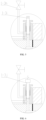
- a screw extruder including a threaded sleeve 1-a and a threaded rod 1-b penetrating in the threaded sleeve 1-a.
- the threaded rod 1-b may include a feed section 1-5d, a compression section (represented as a first compression section 1-5c and a second compression section 1-5b as shown in FIG. 1 , and also represented in other forms) and a metering section 1-5a which are disposed in sequence.
- the threaded sleeve 1-a includes a gas collection chamber 1-3g and an exhaust hole 1-3d.
- the gas collection chamber 1-3g is opened and disposed on an inner wall of a junction of the compression section and the metering section 1-5.
- the exhaust hole 1-3d is in communication with the gas collection chamber 1-3g.
- the threaded sleeve 1-a is equipped with an on-off valve 1-3 to open and close the exhaust hole 1-3d.
- the threaded sleeve 1-a is disposed with an external heater at outside to provide heat.
- the threaded rod 1-b may include: the feed section 1-5d, the compression section and the metering section 1-5a which are disposed in sequence.
- a polylactic-acid raw material when entering the feed section 1-5d changes gradually from a solid material into a molten melt with an increase of a temperature step by step and under an action of shear heat between raw materials.
- the compression section the solid material is fully melted to a liquid phase by compression and shear.
- structures of a small portion of the raw material become unstable and undergo chemical changes, resulting in a hydrolysis.
- a gas generated has a serious impact on subsequent spinning.
- the gas is collected by the gas collection chamber 1-3g located at an end of the compression section.
- the gas generated by the hydrolysis is discharged from the exhaust hole 1-3d by controlling the on-off valve 1-3.
- the melt enters the metering section 1-5a, the gas is removed in time, thereby overcoming the serious adverse impact of the gas from the hydrolysis on the spinning. The unfavorable situation of end breakage is eliminated, and a subsequent spinning quality and a spinning efficiency are guaranteed.
- the threaded sleeve 1-a may include a first threaded sleeve 1-1 and a second threaded sleeve 1-4 that are butted.
- the threaded rod 1-b is penetrated in the first threaded sleeve 1-1 and the second threaded sleeve 1-4.
- the first threaded sleeve 1-1 is provided with the exhaust hole 1-3d and is mounted with the on-off valve 1-3.
- An inner wall of an end of the first threaded sleeve 1-1 close to the second threaded sleeve 1-4 is disposed with a recess.
- a sealing gasket 1-3f is provided between the first threaded sleeve 1-1 and the second threaded sleeve 1-4; and/or an inner wall of an end of the second threaded sleeve 1-4 close to the first threaded sleeve 1 is disposed with the recess, and the first threaded sleeve 1-1, the sealing gasket 1-3f, the second threaded sleeve 1-4 and the threaded rod 1-b together enclose a gas collection chamber 1-3g.
- the threaded sleeve 1-a is disposed in a form of a combination of the first threaded sleeve 1-1 and the second threaded sleeve 1-4 to form the gas collection chamber 1-3g.
- a sealing gasket 1-3f being disposed between the first threaded sleeve 1-1 and the second threaded sleeve 1-4 means that the sealing gasket 1-3f is disposed at a buttting surface of the first threaded sleeve 1-1 and the second threaded sleeve 1.
- the first threaded sleeve 1-1 and the second threaded sleeve 1-4 can be connected by bolts, and the sealing gasket 1-3f is used to ensure a leakproofness of the gas collection chamber 1-3g.
- the above-described 'and/or an inner wall of an end of the second threaded sleeve 1-4 close to the first threaded sleeve 1 being disposed with the recess' means that: based on the inner wall of the end of the first threaded sleeve 1-1 close to the second threaded sleeve 1-4 being disposed with the recess, an inner wall of an end of the second threaded sleeve 1-4 close to the first threaded sleeve 1-1 may be disposed with the recess to form a portion of the gas collection chamber 1-3g; or the inner wall of the end close to the second threaded sleeve 1-4 of the first threaded sleeve 1-1 may be disposed with the recess alone, or the inner wall of the end of the second threaded sleeve 1-4 close to the first threaded sleeve 1-1 may be disposed with the recess alone.
- the feed section 1-5d is configured as a single-thread threaded rod to complete a feeding; the compression section is configured as a double-thread threaded rod to reduce the shear heat of the compression section, thereby reducing an over-temperature phenomenon of the compression section.
- the compression section may include a first compression section 1-5c and a second compression section 1-5b.
- the first compression section 1-5c and the second compression section 1-5b are configured in a form of the double-thread threaded rod.
- the threaded rod 1-b may include a feed section 1-5d, a first compression section 1-5c, a second compression section 1-5b and a metering section 1-5a disposed in sequence.
- groove depths of the first compression section 1-5c and the second compression section 1-5b gradually decrease, and a variation of the groove depth of the second compression section 1-5b is less than that of the first compression section 1-5c.
- the groove depth of the first compression section 1-5c gradually decreases, and the variation of the groove depth thereof is relatively large, so that a material in a solid phase is compressed and sheared, and fully melted to a liquid phase, and then passes through the second compression section 1-5b with a decreasing groove depth and with a small variation of the groove depth.
- the material in a solid phase is fully melted into a liquid, and on the other hand, there is a relative space to store the gas generated after hydrolysis.
- the above-mentioned variation of the groove depth refers to an amount of variation of the groove depth per unit length along the material delivering direction in the screw extruder.
- the large variation and small variation of the groove depth are relative to one another.
- the threaded sleeve 1-a may include an electric contact pressure gauge 1-2.
- a measurement end of the electric contact pressure gauge 1-2 is exposed to the gas collection chamber 1-3g.
- the gas collection chamber 1-3g is used to collect the gas generated by the hydrolysis of the material.
- a pressure generated when the collected gas reaches a certain volume, is reflected on the electric contact pressure gauge 1-2, and actions of the on-off valve 1-3 are assisted by the electric contact pressure gauge 1-2.
- the threaded sleeve 1-a may include a base seat 1-c disposed on an outer edge.
- the exhaust hole 1-3d is in a L-shape and disposed within the base seat 1-c. Two ends of the exhaust hole 1-3d are in communication with the gas collection chamber 1-3g and the external atmosphere respectively.
- the on-off valve 1-3 is mounted on the base seat 1-c.
- the on-off valve 1-3 may include a valve body 1-3b, a packing sealer 1-3c, a valve stem 1-3a and a bushing 1-3e.
- a portion of the valve body 1-3b is disposed within the base seat 1-c and another portion of the valve body 1-3b protrudes from the base seat 1-c (as shown in FIG. 4 , a portion of the valve body 1-3b is disposed within the base seat 1-c, and the another portion of the valve body 1-3b is exposed from the base seat 1-c).
- the valve stem 1-3a is movably penetrated in the valve body 1-3b. As the valve body 1-3b partially is disposed within the base seat 1-c, so that the valve stem 1-3a is also movably penetrated in the base seat 1-c.
- the packing sealer 1-3c is disposed within the base seat 1-c and disposed between the base seat 1-c and the valve stem 1-3a to seal a gap area between the base seat 1-c and the valve stem 1-3a, so that the gas is fully discharged from the exhaust hole 1-3d when the gas is discharged.
- An end of the valve stem 1-3a is configured to be in a form of arc to close or communicate a L-shaped bend of the exhaust hole 1-3d.
- the bushing 1-3e is disposed at the L-shaped bend of the exhaust hole 1-3d of the base seat 1-c, and the bushing 1-3e is configured to abut against an arc surface of an end of the valve stem 1-3a to ensure a good leakproofness when the valve stem 1-3a closes the exhaust hole 1-3d.
- the exhaust hole 1-3d is blocked or communicated.
- the gas in the gas collection chamber 1-3g is discharged by opening the exhaust hole 1-3d in conjunction with an indication of the electric contact pressure gauge 1-2.
- the on-off valve 1-3 may be configured as a manual needle valve 1-3i.
- the on-off valve 1-3 may be configured as an electric needle valve 1-3j.
- the electric needle valve 1-3j may be controlled to open at a fixed value in combination with the electric contact pressure gauge 1-2.
- an end of the exhaust hole 1-3d directly is in communication with the external atmosphere.
- an electric vacuum pump 1-3h may be added at an end of the exhaust hole 1-3d to quickly discharge the gas through pumping.
- the electric vacuum pump may also be combined with the electric contact pressure gauge 1-2 to control the electric vacuum pump 1-3h to automatically start to exhaust the gas at a preset gas pressure.
- the metering section 1-5a may sequentially include a first double-thread structure 1-5a3, a diamond shape separated structure 1-5a2 and a second double-thread structure 1-5a1.
- the diamond shape separated structure 1-5a2 is configured as a diamond shape formed by an integrated milling or a diamond pin formed by processing.
- an upper row of diagrams in FIG. 3 show an integrated milled diamond shape structure
- a lower row of diagrams in FIG. 3 show a diamond shape separated structure 1-5a2 processed from diamond shape pins.
- the diamond shape separated structure 1-5a2 can further promote a mixing and homogenization of the melt.
- a portion of a threaded rod of the first double-thread structure 1-5a3 is distributed and laid with a plurality of V-shaped grooves 1-5a3-1 ⁇ 4 along a spiral annular shape, and the V-shaped groove has a length extending on the entire first double-thread structure 1-5a3 to achieve an advantageous effect of reducing unevennesses of the melt about temperature and intrinsic viscosity.
- a diameter of the diamond shape separated structure 1-5a2 gradually decreases, and a density of distribution of diamonds gradually decreases.
- the diameter of the diamond shape separated structure 1-5a2 gradually decreases to ensure that the material does not flow back and the shear heat is gradually reduced. It can be seen from cross-sectional views G3-G3, G2-G2 and G1-G1 in FIG.
- a length of a single-thread feed section 1-5d is configured to be 9D to 11D; a length of a double-thread compression section is controlled to be 10D to 11D; and a length of the metering section 1-5a is configured to be 9D to 15D.
- a length of the first double-thread structure 1-5a3 is configured to be 4D to 10D; a length of the diamond shape separated structure 1-5a2 is configured to be 3D; and a length of the second double-thread structure 1-5a1 is configured to be 2D.
- an aspect ratio of the threaded rod 1-b is controlled as (28-34): 1.
- a temperature of the screw extruder is controlled in zones as 160°C to 240°C, and a pressure after filtration of the screw extruder is controlled as 80-120kg/cm 2 .
- thread ridges of the feed section 1-5d have equal diameter and single pitch, and thread ridges of the second double-thread structure 1-5a1 have equal distance and equal height, and therefore the melt is fully melted to make the output melt uniform and stable and the pressure at the outlet of the screw extruder is sable, thereby facilitating subsequent spinning to achieve quantitative, constant-pressure and constant-temperature extrusion from a machine head in mixing and extrusion section.
- a combined spinning-drawing-winding machine for industrial polylactic-acid fiber is also provided according to some embodiments of the disclosure, which includes the above-mentioned screw extruder.
- An extrusion head disposed at a head portion of the screw extruder is equipped with a melt pressure sensor, so that the pressure value of the melt may be detected to ensure that a pressure of the head portion of the screw extruder is constant.
Landscapes
- Engineering & Computer Science (AREA)
- Mechanical Engineering (AREA)
- Textile Engineering (AREA)
- Chemical & Material Sciences (AREA)
- Chemical Kinetics & Catalysis (AREA)
- General Chemical & Material Sciences (AREA)
- Extrusion Moulding Of Plastics Or The Like (AREA)
Applications Claiming Priority (3)
| Application Number | Priority Date | Filing Date | Title |
|---|---|---|---|
| CN202122407182.2U CN216192890U (zh) | 2021-09-30 | 2021-09-30 | 一种螺杆挤压机及聚乳酸产业用纤维纺丝牵伸卷绕联合机 |
| CN202111163903.8A CN113737290B (zh) | 2021-09-30 | 2021-09-30 | 一种螺杆挤压机及聚乳酸产业用纤维纺丝牵伸卷绕联合机 |
| PCT/CN2022/122718 WO2023051720A1 (zh) | 2021-09-30 | 2022-09-29 | 一种螺杆挤压机及聚乳酸产业用纤维纺丝牵伸卷绕联合机 |
Publications (2)
| Publication Number | Publication Date |
|---|---|
| EP4411033A1 true EP4411033A1 (de) | 2024-08-07 |
| EP4411033A4 EP4411033A4 (de) | 2025-10-01 |
Family
ID=85781377
Family Applications (1)
| Application Number | Title | Priority Date | Filing Date |
|---|---|---|---|
| EP22875101.2A Pending EP4411033A4 (de) | 2021-09-30 | 2022-09-29 | Schneckenextruder sowie kombinierte faserspinn-, streck- und wickelmaschine für die polymilchsäureindustrie |
Country Status (2)
| Country | Link |
|---|---|
| EP (1) | EP4411033A4 (de) |
| WO (1) | WO2023051720A1 (de) |
Families Citing this family (2)
| Publication number | Priority date | Publication date | Assignee | Title |
|---|---|---|---|---|
| CN116945542B (zh) * | 2023-08-04 | 2024-01-26 | 广东科腾精密机械有限公司 | 液态硅胶射出成型机用螺杆、射出成型机及其使用方法 |
| CN118849375B (zh) * | 2024-09-26 | 2024-12-31 | 浙江百纳橡塑设备有限公司 | 一种橡胶管挤出机头 |
Family Cites Families (16)
| Publication number | Priority date | Publication date | Assignee | Title |
|---|---|---|---|---|
| USRE23880E (en) * | 1950-03-07 | 1954-09-28 | Extruder | |
| JPS5120080U (de) * | 1974-08-02 | 1976-02-14 | ||
| JPS5756511A (en) * | 1980-09-22 | 1982-04-05 | Toray Ind Inc | Melt-spinning method |
| DE4114541C2 (de) * | 1990-12-14 | 1994-05-26 | Berstorff Gmbh Masch Hermann | Entgasungsextruder |
| JP3377823B2 (ja) * | 1993-03-29 | 2003-02-17 | 積水化学工業株式会社 | 樹脂加工機のガス抜き装置 |
| JPH09131727A (ja) * | 1995-11-07 | 1997-05-20 | Japan Steel Works Ltd:The | 着色剤マスターバッチの製造装置 |
| JP4085125B1 (ja) * | 2007-06-18 | 2008-05-14 | 有限会社ケイシーケイ応用技術研究所 | 超微粉体を樹脂に混練分散する方法および混練装置 |
| JP6055710B2 (ja) * | 2013-04-02 | 2016-12-27 | 日立マクセル株式会社 | ベントアップ検出機構、ベントアップ防止装置、成形体の製造方法及び成形体の成形装置 |
| CN203357859U (zh) * | 2013-06-09 | 2013-12-25 | 北京中丽制机工程技术有限公司 | 一种纺丝用螺杆 |
| CN104589620A (zh) * | 2013-11-03 | 2015-05-06 | 北京化工大学 | 一种单周旋转往复三次的往复式单螺杆销钉挤出机及其高效混炼元件 |
| CN203919666U (zh) * | 2014-04-30 | 2014-11-05 | 泉州东方机械有限公司 | 一种高剪切高混合挤出机螺杆 |
| CN105946169B (zh) * | 2016-07-01 | 2018-01-30 | 何宏雷 | Pet排气式注塑一体机 |
| CN213055935U (zh) * | 2020-08-17 | 2021-04-27 | 武汉海派特塑料机械有限公司 | 锥双挤出机的直通式排气装置 |
| CN216192890U (zh) * | 2021-09-30 | 2022-04-05 | 北京中丽制机工程技术有限公司 | 一种螺杆挤压机及聚乳酸产业用纤维纺丝牵伸卷绕联合机 |
| CN113737290B (zh) * | 2021-09-30 | 2025-04-01 | 北京中丽制机工程技术有限公司 | 一种螺杆挤压机及聚乳酸产业用纤维纺丝牵伸卷绕联合机 |
| CN115058783A (zh) * | 2022-06-24 | 2022-09-16 | 宁波禾素纤维有限公司 | 一种制备phvb与pla共混生物基纤维的原料共挤装置 |
-
2022
- 2022-09-29 WO PCT/CN2022/122718 patent/WO2023051720A1/zh not_active Ceased
- 2022-09-29 EP EP22875101.2A patent/EP4411033A4/de active Pending
Also Published As
| Publication number | Publication date |
|---|---|
| EP4411033A4 (de) | 2025-10-01 |
| WO2023051720A1 (zh) | 2023-04-06 |
Similar Documents
| Publication | Publication Date | Title |
|---|---|---|
| EP4411033A1 (de) | Schneckenextruder sowie kombinierte faserspinn-, streck- und wickelmaschine für die polymilchsäureindustrie | |
| CN216192890U (zh) | 一种螺杆挤压机及聚乳酸产业用纤维纺丝牵伸卷绕联合机 | |
| CN113737290B (zh) | 一种螺杆挤压机及聚乳酸产业用纤维纺丝牵伸卷绕联合机 | |
| US2370469A (en) | Apparatus for extrusion of organic materials | |
| JP2014525390A (ja) | ハニカム構造物を有するセラミック成形デバイスおよび方法 | |
| CN115647564A (zh) | 一种增材式填丝自调节搅拌摩擦焊的装置及其方法 | |
| EP2047750A1 (de) | Maschine zur Herstellung von Hefenudeln | |
| CN208375653U (zh) | 一种平行双螺杆挤出机 | |
| RU185843U1 (ru) | Экструдер для переработки разнородных вторичных полимерных материалов | |
| CN214726303U (zh) | 一种pla吸管挤出机 | |
| US3467513A (en) | Process and apparatus for high pressure extrusion of glassprocess and apparatus for high pressure extrusion of glass | |
| CN209381351U (zh) | 单螺杆挤出机用高效节能型螺杆 | |
| JP4272502B2 (ja) | 射出成形方法 | |
| CN207901639U (zh) | 一种高效节能pc造料锥双螺杆 | |
| CN207047376U (zh) | 一种纺丝装置 | |
| CN115058783A (zh) | 一种制备phvb与pla共混生物基纤维的原料共挤装置 | |
| CN209332735U (zh) | 制丸机 | |
| CN223573778U (zh) | 螺杆及挤出机 | |
| CN111155351B (zh) | 一种磨浆机 | |
| CN214491148U (zh) | 一种预混合塑化连续自动密炼机用三头螺纹剪切转子 | |
| RU223527U1 (ru) | Экструдер | |
| CN202968784U (zh) | 再生聚酯纤维纺丝用深槽螺杆 | |
| CN219861711U (zh) | 一种超细纤维丝用熔融挤出装置 | |
| CN216544655U (zh) | 一种用于管材生产的螺杆 | |
| CN208215971U (zh) | 一种挤出机螺杆 |
Legal Events
| Date | Code | Title | Description |
|---|---|---|---|
| STAA | Information on the status of an ep patent application or granted ep patent |
Free format text: STATUS: THE INTERNATIONAL PUBLICATION HAS BEEN MADE |
|
| PUAI | Public reference made under article 153(3) epc to a published international application that has entered the european phase |
Free format text: ORIGINAL CODE: 0009012 |
|
| STAA | Information on the status of an ep patent application or granted ep patent |
Free format text: STATUS: REQUEST FOR EXAMINATION WAS MADE |
|
| 17P | Request for examination filed |
Effective date: 20240327 |
|
| AK | Designated contracting states |
Kind code of ref document: A1 Designated state(s): AL AT BE BG CH CY CZ DE DK EE ES FI FR GB GR HR HU IE IS IT LI LT LU LV MC MK MT NL NO PL PT RO RS SE SI SK SM TR |
|
| DAV | Request for validation of the european patent (deleted) | ||
| DAX | Request for extension of the european patent (deleted) | ||
| REG | Reference to a national code |
Ref country code: DE Ref legal event code: R079 Free format text: PREVIOUS MAIN CLASS: D01D0001040000 Ipc: B29C0048050000 |
|
| A4 | Supplementary search report drawn up and despatched |
Effective date: 20250828 |
|
| RIC1 | Information provided on ipc code assigned before grant |
Ipc: B29C 48/05 20190101AFI20250822BHEP Ipc: D01D 1/04 20060101ALI20250822BHEP Ipc: B29C 48/76 20190101ALI20250822BHEP Ipc: B29C 48/92 20190101ALI20250822BHEP Ipc: B29C 45/63 20060101ALI20250822BHEP Ipc: B29C 48/685 20190101ALI20250822BHEP Ipc: B29B 7/84 20060101ALN20250822BHEP Ipc: D01D 1/09 20060101ALN20250822BHEP Ipc: B29C 48/53 20190101ALN20250822BHEP Ipc: B29B 7/80 20060101ALN20250822BHEP |