EP4411024A2 - Wasserelektrolysevorrichtung, wasserelektrolyseverfahren und verfahren zur wiederverwertung einer wiederaufladbaren nickel-wasserstoff-batterie - Google Patents
Wasserelektrolysevorrichtung, wasserelektrolyseverfahren und verfahren zur wiederverwertung einer wiederaufladbaren nickel-wasserstoff-batterie Download PDFInfo
- Publication number
- EP4411024A2 EP4411024A2 EP23218137.0A EP23218137A EP4411024A2 EP 4411024 A2 EP4411024 A2 EP 4411024A2 EP 23218137 A EP23218137 A EP 23218137A EP 4411024 A2 EP4411024 A2 EP 4411024A2
- Authority
- EP
- European Patent Office
- Prior art keywords
- tank
- water electrolysis
- power source
- gas
- electrolysis apparatus
- Prior art date
- Legal status (The legal status is an assumption and is not a legal conclusion. Google has not performed a legal analysis and makes no representation as to the accuracy of the status listed.)
- Pending
Links
Images


Classifications
-
- C—CHEMISTRY; METALLURGY
- C25—ELECTROLYTIC OR ELECTROPHORETIC PROCESSES; APPARATUS THEREFOR
- C25B—ELECTROLYTIC OR ELECTROPHORETIC PROCESSES FOR THE PRODUCTION OF COMPOUNDS OR NON-METALS; APPARATUS THEREFOR
- C25B9/00—Cells or assemblies of cells; Constructional parts of cells; Assemblies of constructional parts, e.g. electrode-diaphragm assemblies; Process-related cell features
- C25B9/70—Assemblies comprising two or more cells
-
- C—CHEMISTRY; METALLURGY
- C25—ELECTROLYTIC OR ELECTROPHORETIC PROCESSES; APPARATUS THEREFOR
- C25B—ELECTROLYTIC OR ELECTROPHORETIC PROCESSES FOR THE PRODUCTION OF COMPOUNDS OR NON-METALS; APPARATUS THEREFOR
- C25B1/00—Electrolytic production of inorganic compounds or non-metals
- C25B1/01—Products
- C25B1/02—Hydrogen or oxygen
- C25B1/04—Hydrogen or oxygen by electrolysis of water
-
- C—CHEMISTRY; METALLURGY
- C25—ELECTROLYTIC OR ELECTROPHORETIC PROCESSES; APPARATUS THEREFOR
- C25B—ELECTROLYTIC OR ELECTROPHORETIC PROCESSES FOR THE PRODUCTION OF COMPOUNDS OR NON-METALS; APPARATUS THEREFOR
- C25B11/00—Electrodes; Manufacture thereof not otherwise provided for
- C25B11/02—Electrodes; Manufacture thereof not otherwise provided for characterised by shape or form
-
- C—CHEMISTRY; METALLURGY
- C25—ELECTROLYTIC OR ELECTROPHORETIC PROCESSES; APPARATUS THEREFOR
- C25B—ELECTROLYTIC OR ELECTROPHORETIC PROCESSES FOR THE PRODUCTION OF COMPOUNDS OR NON-METALS; APPARATUS THEREFOR
- C25B11/00—Electrodes; Manufacture thereof not otherwise provided for
- C25B11/04—Electrodes; Manufacture thereof not otherwise provided for characterised by the material
-
- C—CHEMISTRY; METALLURGY
- C25—ELECTROLYTIC OR ELECTROPHORETIC PROCESSES; APPARATUS THEREFOR
- C25B—ELECTROLYTIC OR ELECTROPHORETIC PROCESSES FOR THE PRODUCTION OF COMPOUNDS OR NON-METALS; APPARATUS THEREFOR
- C25B15/00—Operating or servicing cells
- C25B15/02—Process control or regulation
- C25B15/023—Measuring, analysing or testing during electrolytic production
- C25B15/025—Measuring, analysing or testing during electrolytic production of electrolyte parameters
- C25B15/027—Temperature
-
- C—CHEMISTRY; METALLURGY
- C25—ELECTROLYTIC OR ELECTROPHORETIC PROCESSES; APPARATUS THEREFOR
- C25B—ELECTROLYTIC OR ELECTROPHORETIC PROCESSES FOR THE PRODUCTION OF COMPOUNDS OR NON-METALS; APPARATUS THEREFOR
- C25B15/00—Operating or servicing cells
- C25B15/02—Process control or regulation
- C25B15/023—Measuring, analysing or testing during electrolytic production
- C25B15/025—Measuring, analysing or testing during electrolytic production of electrolyte parameters
- C25B15/029—Concentration
- C25B15/031—Concentration pH
-
- C—CHEMISTRY; METALLURGY
- C25—ELECTROLYTIC OR ELECTROPHORETIC PROCESSES; APPARATUS THEREFOR
- C25B—ELECTROLYTIC OR ELECTROPHORETIC PROCESSES FOR THE PRODUCTION OF COMPOUNDS OR NON-METALS; APPARATUS THEREFOR
- C25B15/00—Operating or servicing cells
- C25B15/04—Regulation of the inter-electrode distance
-
- C—CHEMISTRY; METALLURGY
- C25—ELECTROLYTIC OR ELECTROPHORETIC PROCESSES; APPARATUS THEREFOR
- C25B—ELECTROLYTIC OR ELECTROPHORETIC PROCESSES FOR THE PRODUCTION OF COMPOUNDS OR NON-METALS; APPARATUS THEREFOR
- C25B15/00—Operating or servicing cells
- C25B15/08—Supplying or removing reactants or electrolytes; Regeneration of electrolytes
-
- C—CHEMISTRY; METALLURGY
- C25—ELECTROLYTIC OR ELECTROPHORETIC PROCESSES; APPARATUS THEREFOR
- C25B—ELECTROLYTIC OR ELECTROPHORETIC PROCESSES FOR THE PRODUCTION OF COMPOUNDS OR NON-METALS; APPARATUS THEREFOR
- C25B15/00—Operating or servicing cells
- C25B15/08—Supplying or removing reactants or electrolytes; Regeneration of electrolytes
- C25B15/083—Separating products
-
- C—CHEMISTRY; METALLURGY
- C25—ELECTROLYTIC OR ELECTROPHORETIC PROCESSES; APPARATUS THEREFOR
- C25B—ELECTROLYTIC OR ELECTROPHORETIC PROCESSES FOR THE PRODUCTION OF COMPOUNDS OR NON-METALS; APPARATUS THEREFOR
- C25B9/00—Cells or assemblies of cells; Constructional parts of cells; Assemblies of constructional parts, e.g. electrode-diaphragm assemblies; Process-related cell features
- C25B9/17—Cells comprising dimensionally-stable non-movable electrodes; Assemblies of constructional parts thereof
- C25B9/19—Cells comprising dimensionally-stable non-movable electrodes; Assemblies of constructional parts thereof with diaphragms
-
- H—ELECTRICITY
- H01—ELECTRIC ELEMENTS
- H01M—PROCESSES OR MEANS, e.g. BATTERIES, FOR THE DIRECT CONVERSION OF CHEMICAL ENERGY INTO ELECTRICAL ENERGY
- H01M10/00—Secondary cells; Manufacture thereof
- H01M10/24—Alkaline accumulators
- H01M10/30—Nickel accumulators
-
- H—ELECTRICITY
- H01—ELECTRIC ELEMENTS
- H01M—PROCESSES OR MEANS, e.g. BATTERIES, FOR THE DIRECT CONVERSION OF CHEMICAL ENERGY INTO ELECTRICAL ENERGY
- H01M10/00—Secondary cells; Manufacture thereof
- H01M10/34—Gastight accumulators
- H01M10/345—Gastight metal hydride accumulators
-
- H—ELECTRICITY
- H01—ELECTRIC ELEMENTS
- H01M—PROCESSES OR MEANS, e.g. BATTERIES, FOR THE DIRECT CONVERSION OF CHEMICAL ENERGY INTO ELECTRICAL ENERGY
- H01M10/00—Secondary cells; Manufacture thereof
- H01M10/54—Reclaiming serviceable parts of waste accumulators
-
- Y—GENERAL TAGGING OF NEW TECHNOLOGICAL DEVELOPMENTS; GENERAL TAGGING OF CROSS-SECTIONAL TECHNOLOGIES SPANNING OVER SEVERAL SECTIONS OF THE IPC; TECHNICAL SUBJECTS COVERED BY FORMER USPC CROSS-REFERENCE ART COLLECTIONS [XRACs] AND DIGESTS
- Y02—TECHNOLOGIES OR APPLICATIONS FOR MITIGATION OR ADAPTATION AGAINST CLIMATE CHANGE
- Y02E—REDUCTION OF GREENHOUSE GAS [GHG] EMISSIONS, RELATED TO ENERGY GENERATION, TRANSMISSION OR DISTRIBUTION
- Y02E60/00—Enabling technologies; Technologies with a potential or indirect contribution to GHG emissions mitigation
- Y02E60/30—Hydrogen technology
- Y02E60/36—Hydrogen production from non-carbon containing sources, e.g. by water electrolysis
-
- Y—GENERAL TAGGING OF NEW TECHNOLOGICAL DEVELOPMENTS; GENERAL TAGGING OF CROSS-SECTIONAL TECHNOLOGIES SPANNING OVER SEVERAL SECTIONS OF THE IPC; TECHNICAL SUBJECTS COVERED BY FORMER USPC CROSS-REFERENCE ART COLLECTIONS [XRACs] AND DIGESTS
- Y02—TECHNOLOGIES OR APPLICATIONS FOR MITIGATION OR ADAPTATION AGAINST CLIMATE CHANGE
- Y02W—CLIMATE CHANGE MITIGATION TECHNOLOGIES RELATED TO WASTEWATER TREATMENT OR WASTE MANAGEMENT
- Y02W30/00—Technologies for solid waste management
- Y02W30/50—Reuse, recycling or recovery technologies
- Y02W30/84—Recycling of batteries or fuel cells
Definitions
- the present disclosure relates to a water electrolysis apparatus, a water electrolysis method and a method of recycling a nickel-hydrogen rechargeable battery.
- H 2 gas The demand for hydrogen (H 2 ) gas as energy for fuel cell vehicles and for power generation has increased in recent years, and research into methods of producing H 2 gas also has advanced.
- An example of a method of producing H 2 gas is a method of separating water (H 2 O) into and recovering hydrogen (H 2 ) gas and oxygen (O 2 ) gas by a water electrolysis reaction.
- JP-A Japanese Patent Application Laid-Open ( JP-A) No. 2021-017628 discloses a hydrogen gas producing device including a water electrolysis cell and a power source.
- the water electrolysis cell includes a first electrode, a second electrode and an alkaline aqueous solution.
- the first electrode and the second electrode each contact the alkaline aqueous solution, and are disposed so as to be apart from one another.
- the first electrode contains a hydrogen absorbing alloy.
- the hydrogen absorbing alloy has a dissociation equilibrium pressure of 0.2 MPa or more at 20°C.
- the first electrode and the second electrode are each connected to the power source.
- the power source applies voltage between the electrodes such that the first electrode becomes the negative electrode and the second electrode becomes the positive electrode, and hydrogen gas is generated at the first electrode by electrolysis of the alkaline aqueous solution.
- the present disclosure provides a water electrolysis apparatus and a water electrolysis method that can safely retrieve H 2 gas and O 2 gas having high purities. Further, the present disclosure also provides a method of recycling a nickel-hydrogen rechargeable battery that can safely retrieve H 2 gas and O 2 gas having high purities, re-using a used nickel-hydrogen rechargeable battery.
- a first aspect of the present disclosure provides a water electrolysis apparatus including:
- a second aspect of the present disclosure provides the water electrolysis apparatus according to the first aspect, wherein at least one of the first tank or the second tank is a nickel-hydrogen rechargeable battery.
- a third aspect of the present disclosure provides the water electrolysis apparatus according to the second aspect, wherein the nickel-hydrogen rechargeable battery is a used rechargeable battery.
- a fourth aspect of the present disclosure provides the water electrolysis apparatus according to any one of the first to third aspects, wherein the O 2 gas extraction opening and the H 2 gas extraction opening are respectively provided at gravitational direction upper portions of the first tank and the second tank.
- a fifth aspect of the present disclosure provides the water electrolysis apparatus according to any one of the first to fourth aspects, wherein the supply opening and the discharge opening of the first tank, and the supply opening and the discharge opening of the second tank, are provided such that the H 2 O flows from a lower portion toward an upper portion in a gravitational direction.
- a sixth aspect of the present disclosure provides the water electrolysis apparatus according to any one of the first to fifth aspects, wherein the electrolytic solution has a pH of 15 or more.
- a seventh aspect of the present disclosure provides the water electrolysis apparatus according to any one of the first to sixth aspects, wherein a shortest distance between the positive electrode and the negative electrode is from more than 0 mm to 35 mm.
- An eighth aspect of the present disclosure provides the water electrolysis apparatus according to any one of the first to seventh aspects, wherein an overall temperature of the water electrolysis apparatus is from 40°C to 80°C.
- a ninth aspect of the present disclosure provides a water electrolysis method using a water electrolysis apparatus including:
- a tenth aspect of the present disclosure provides the water electrolysis method according to the ninth aspect, wherein a nickel-hydrogen rechargeable battery is used as at least one of the first tank or the second tank.
- An eleventh aspect of the present disclosure provides the water electrolysis method according to the tenth aspect, wherein the nickel-hydrogen rechargeable battery is a used rechargeable battery.
- a twelfth aspect of the present disclosure provides the water electrolysis method according to any one of the ninth to eleventh aspects, wherein the O 2 gas extraction opening and the H 2 gas extraction opening are respectively provided at gravitational direction upper portions of the first tank and the second tank.
- a thirteenth aspect of the present disclosure provides the water electrolysis method according to any one of the ninth to twelfth aspects, wherein the supply opening and the discharge opening of the first tank, and the supply opening and the discharge opening of the second tank, are provided such that the H 2 O flows from a lower portion toward an upper portion in a gravitational direction.
- a fourteenth aspect of the present disclosure provides the water electrolysis method according to any one of the ninth to thirteenth aspects, wherein the electrolytic solution has a pH of 15 or more.
- a fifteenth aspect of the present disclosure provides the water electrolysis method according to any one of the ninth to fourteenth aspects, wherein a shortest distance between the positive electrode and the negative electrode is from more than 0 mm to 35 mm.
- a sixteenth aspect of the present disclosure provides the water electrolysis method according to any one of the ninth to fifteenth aspects, wherein an overall temperature of the water electrolysis apparatus is from 40°C to 80°C.
- a seventeenth aspect of the present disclosure provides a method of recycling a nickel-hydrogen rechargeable battery, the method including using a used nickel-hydrogen rechargeable battery as at least one of a first tank or a second tank in a water electrolysis apparatus, the water electrolysis apparatus including:
- a water electrolysis apparatus and a water electrolysis method that can safely extract H 2 gas and O 2 gas having high purities. Further, in accordance with the present disclosure, there can be provided a method of recycling a nickel-hydrogen rechargeable battery that re-uses a used nickel-hydrogen rechargeable battery and can safely extract H 2 gas and O 2 gas having high purities.
- a water electrolysis apparatus, a water electrolysis method and a method of recycling a nickel-hydrogen rechargeable battery according to the present disclosure are described in detail hereinafter with reference to the drawings.
- the respective drawings described hereinafter are schematic illustrations, and sizes and shapes of respective portions are exaggerated when appropriate in order to facilitate understanding.
- the expressions of simply "above” and “below” encompass both cases in which the given member is disposed directly above or directly below the another member so as to contact the another member, and cases in which the given member is disposed above or below the another member with a separate member disposed between the given member and the another member, unless otherwise indicated.
- the water electrolysis apparatus includes: a power source; an electrolytic solution; a first tank immersed in the electrolytic solution and including a positive electrode connected to the power source, a supply opening and a discharge opening for H 2 O, and an O 2 gas extraction opening; and a second tank immersed in the electrolytic solution and including a negative electrode connected to the power source, a supply opening and a discharge opening for H 2 O, and an H 2 gas extraction opening. Voltage is maintained by the power source such that the potential of the positive electrode is higher than the potential of the negative electrode, thereby enabling O 2 gas to be extracted from the first tank, and H 2 gas to be extracted from the second tank.
- Fig. 1 is a schematic perspective view illustrating an example of a water electrolysis apparatus in an embodiment of the present disclosure.
- a water electrolysis apparatus 20A includes a power source 3, a resistor 30 that is an example of an electronic load, a housing 4 that accommodates an electrolytic solution 40, a first tank 100A and a second tank 200A that are immersed in the electrolytic solution 40 in the housing 4, and a distilling device 5. Adjustment of the raising and the lowering of the voltage is carried out by the power source 3 and the resistor 30, and maintaining at a desired voltage can be carried out. Note that a power source that incorporates the function of an electronic load therein may be used.
- the first tank 100A includes a positive electrode and a negative electrode, and this positive electrode is connected to the power source 3 and the resistor 30.
- the second tank 200A includes a positive electrode and a negative electrode, and this negative electrode is connected to the power source 3 and the resistor 30.
- the first tank 100A has a supply opening for water.
- a water supply pipe (not illustrated) equipped with a water supplying pump is connected to this supply opening, and the water supplying pump (not illustrated) is driven to supply water (H 2 O).
- the first tank 100A has a discharge opening for water.
- a water discharge pipe (not illustrated) is connected to this discharge opening, and excess water in the first tank 100A is discharged from the discharge opening.
- the second tank 200A has a supply opening for water.
- a water supply pipe (not illustrated) equipped with a water supplying pump 6 is connected to this supply opening, and the water supplying pump 6 is driven to supply water (H 2 O).
- the second tank 200A has a discharge opening for water.
- a water discharge pipe (not illustrated) is connected to this discharge opening, and excess water in the second tank 200A is discharged from the discharge opening.
- the first tank 100A has a discharge path 101 for oxygen (O 2 ), and the discharge path 101 is connected to the distilling device 5.
- the second tank 200A has a discharge path 201 for hydrogen (H 2 ).
- Electrolytic solution is accommodated in the distilling device 5.
- the electrolytic solution in the distilling device 5 and the electrolytic solution 40 in the housing 4 are circulated through a flow pipe (not illustrated) that is equipped with a liquid feeding pump 7.
- the distilling device 5 has a discharge opening 8 for water vapor (H 2 O).
- a resistor is used as the electronic load.
- a variable resistor is also usable.
- the water electrolysis apparatus 20A uses nickel-hydrogen rechargeable batteries as both the first tank 100A that includes a positive electrode and the second tank 200A that includes a negative electrode. These nickel-hydrogen rechargeable batteries may be used nickel-hydrogen rechargeable batteries.
- the voltage is maintained by the power source 3 and the resistor 30 such that the potential of the positive electrode of the first tank 100A is higher than the potential of the negative electrode of the second tank 200A. Due thereto, a water electrolysis reaction occurs in the water (H 2 O) that has been supplied to the first tank 100A and the second tank 200A, and O 2 gas is generated from the first tank 100A. The generated O 2 gas is transferred through the discharge path 101 to the distilling device 5, and, in the distilling device 5, is reduced to water vapor (H 2 O), which is then extracted from the discharge opening 8. Further, a water electrolysis reaction occurs in the second tank 200A to generate H 2 gas, and this H 2 gas is extracted from the discharge path 201.
- the potential difference between the positive electrode and the negative electrode is maintained at 1.48 V or more. Note that the reaction formulas of the positive electrode and the negative electrode are as follows.
- the potential difference which is obtained by subtracting the potential of the negative electrode of the second tank from the potential of the positive electrode of the first tank, is more preferably in the range of from 1.48 V to 2.00 V, and from the standpoint of efficiency, is even more preferably in the range of from 1.55 V to 1.80 V.
- the O 2 gas extraction opening of the first tank 100A i.e., the entrance to the discharge path 101 from the first tank 100A
- the H 2 gas extraction opening of the second tank 200A is preferably provided at the gravitational direction upper portion of the second tank 200A.
- the supply opening and discharge opening for water (H 2 O) at the first tank 100A, and the supply opening and the discharge opening for water at the second tank 200A are all provided such that H 2 O flows from a lower portion toward an upper portion in the gravitational direction.
- the water supply opening be provided at the lower portion in the gravitational direction, and that the water discharge opening be provided at the upper portion in the gravitational direction.
- FIG. 2 Another embodiment of the water electrolysis apparatus according to the present disclosure is described with reference to Fig. 2 . Note that elements that are the same as those in the water electrolysis apparatus illustrated in Fig. 1 are denoted by the same reference numerals.
- Fig. 2 is a schematic perspective view illustrating an example of a water electrolysis apparatus in an embodiment of the present disclosure.
- a water electrolysis apparatus 20B includes a power source 3, a resistor 30, a housing 4 that accommodates an electrolytic solution 40, a first tank 100B and a second tank 200B that are immersed in the electrolytic solution 40 in the housing 4, and a distilling device 5.
- plural nickel-hydrogen rechargeable batteries In Fig. 2 , a set of six nickel-hydrogen rechargeable batteries) are used as each of the first tank 100B and the second tank 200B.
- the six nickel-hydrogen rechargeable batteries in the first tank 100B each include a positive electrode and a negative electrode, and all of the positive electrodes are connected to the power source 3 and the resistor 30.
- the six nickel-hydrogen rechargeable batteries in the second tank 200B each include a positive electrode and a negative electrode, and all of the negative electrodes are connected to the power source 3 and the resistor 30.
- the first tank 100B has a supply opening for water.
- a water supply pipe (not illustrated) equipped with a water supplying pump is connected to this supply opening, and water (H 2 O) is supplied when the water supplying pump (not illustrated) is driven.
- the second tank 200B has a supply opening for water.
- a water supply pipe (not illustrated) equipped with a water supplying pump 6 is connected to this supply opening, and water (H 2 O) is supplied when the water supplying pump 6 is driven.
- the first tank 100B has a discharge path 101 for oxygen (O 2 ), and the discharge path 101 is connected to a distilling device 5.
- the second tank 200B has a discharge path 201 for hydrogen (H 2 ).
- An electrolytic solution is accommodated in the distilling device 5.
- the electrolytic solution in the distilling device 5 and the electrolytic solution 40 in the housing 4 are circulated through a flow pipe (not illustrated) that is equipped with a liquid feeding pump 7.
- the distilling device 5 has a discharge opening 8 for water vapor (H 2 O).
- the configuration of connection among the plural nickel-hydrogen rechargeable batteries (in Fig. 2 , a set of six batteries) of the first tank 100B, the plural nickel-hydrogen rechargeable batteries (in Fig. 2 , a set of six batteries) of the second tank 200B, and the power source 3 is illustrated in Fig. 3 .
- illustration of elements other than the first tank 100B, the second tank 200B and the power source 3 is omitted, and illustration of the electronic load is omitted as well.
- Fig. 3 illustration of elements other than the first tank 100B, the second tank 200B and the power source 3 is omitted, and illustration of the electronic load is omitted as well.
- the positive electrodes respectively included in the plural nickel-hydrogen rechargeable batteries of the first tank 100B are all connected (short-circuit connected) to the power source 3.
- the negative electrodes respectively included in the plural nickel-hydrogen rechargeable batteries of the second tank 200B are all connected (short-circuit connected) to the power source 3.
- the nickel-hydrogen rechargeable batteries that are used in the first tank 100B and the second tank 200B in the water electrolysis apparatus 20B may be used nickel-hydrogen rechargeable batteries.
- the voltage is maintained by the power source 3 and the resistor 30 such that the potential of the positive electrodes of the first tank 100B is higher than the potential of the negative electrodes of the second tank 200B. Due thereto, a water electrolysis reaction occurs in the water (H 2 O) that has been supplied to the first tank 100B and the second tank 200B, and O 2 gas is generated from the first tank 100B. The generated O 2 gas is transferred through the discharge path 101 to the distilling device 5, and, in the distilling device 5, is reduced to water vapor (H 2 O), which is then extracted from the discharge opening 8. Further, a water electrolysis reaction occurs in the second tank 200B to generate H 2 gas, and this H 2 gas is extracted from the discharge path 201.
- the potential difference between the positive electrodes and the negative electrodes is maintained at 1.48 V or more.
- the potential difference between the positive electrodes and the negative electrodes is more preferably in the range of from 1.48 V to 2.00 V, and is more preferably in the range of from 1.55 V to 1.80 V.
- the O 2 gas extraction opening of the first tank 100B i.e., the entrance to the discharge path 101 from the first tank 100B, is preferably provided at the gravitational direction upper portion of the first tank 100B.
- the H 2 gas extraction opening of the second tank 200B i.e., the entrance to the discharge path 201 from the second tank 200B, is preferably provided at the gravitational direction upper portion of the second tank 200B.
- the supply opening and discharge opening of water (H 2 O) of the first tank 100B, and the supply opening and the discharge opening of water of the second tank 200B are all provided such that H 2 O flows from a lower portion toward an upper portion in the gravitational direction.
- H 2 O flows from a lower portion toward an upper portion in the gravitational direction.
- the water supply opening be provided at the lower portion in the gravitational direction, and that the water discharge opening be provided at the upper portion in the gravitational direction.
- aspects in which plural positive electrodes are included in the first tank and plural negative electrodes are included in the second tank are not limited to a configuration of short-circuit connection as illustrated in Fig. 3 , and the positive electrodes, the negative electrodes and the power source may be connected in another configuration.
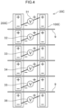
- Fig. 4 is a schematic drawing illustrating a configuration of connecting plural nickel-hydrogen rechargeable batteries of the first tank and plural nickel-hydrogen rechargeable batteries of the second tank and power sources.
- a first tank 100C includes plural (in Fig. 4 , six) nickel-hydrogen rechargeable batteries
- a second tank 200C includes plural (in Fig. 4 , six) nickel-hydrogen rechargeable batteries.
- the water electrolysis apparatus 20C includes plural (in Fig. 4 , six) power sources 31, 32, 33, 34, 35, and 36.
- One power source 31 is connected (normally connected) to the positive electrode of one nickel-hydrogen rechargeable battery included in the first tank 100C and the negative electrode of one nickel-hydrogen rechargeable battery included in the second tank 200C, thereby configuring a circuit.
- each of the remaining power sources 32, 33, 34, 35, and 36 as well is connected (normally connected) to the positive electrode of one nickel-hydrogen rechargeable battery included in the first tank 100C and the negative electrode of one nickel-hydrogen rechargeable battery included in the second tank 200C, thereby configuring a circuit.
- the water electrolysis apparatus 20C includes plural (in Fig. 4 , six) circuits of which the power source, positive electrode and negative electrode of each circuit are connected separately from other circuits.
- the respective circuits are separated by separators 9. Note that, in Fig. 4 , illustration of elements other than the first tank 100C, the second tank 200C and the electrodes 31, 32, 33, 34, 35, and 36 is omitted. Accordingly, in each of the circuits of the water electrolysis apparatus 20C, the positive electrode and the negative electrode are actually connected also to an electronic load, in addition to the power source.
- a first tank in which O 2 gas is generated by a water electrolysis reaction, and a second tank in which H 2 gas is generated, are provided separately in an electrolytic solution. Therefore, O 2 gas and H 2 gas can be extracted separately through respective gas extraction openings of the first tank and the second tank, and H 2 gas and O 2 gas having high purities can be extracted safely.
- nickel-hydrogen rechargeable batteries can be used in one or both of the first tank and the second tank.
- the nickel-hydrogen rechargeable battery may be a used nickel-hydrogen rechargeable battery. Namely, in accordance with the present disclosure, H 2 gas and O 2 gas of high purities can be extracted safely, reutilizing a used nickel-hydrogen rechargeable battery.
- the electrolytic solution in which the first tank and the second tank are immersed preferably has a pH of 14 or more, and more preferably has a pH of 15 or more, and even more preferably has a pH of 16 or more.
- the pH is a value measured at 25°C by using a pH meter.
- the electrolytic solution is not particularly limited, and is preferably an aqueous electrolytic solution.
- an alkaline aqueous solution or the like can be suitably used as the aqueous electrolytic solution.
- the alkaline aqueous solution contains, for example, water and an alkali metal hydroxide dissolved in water.
- the alkali metal hydroxide may have a concentration of, for example, from 1 mol/L to 45 mol/L.
- alkali metal hydroxides include potassium hydroxide (KOH), sodium hydroxide (NaOH), and lithium hydroxide (LiOH).
- the voltage such that the potential difference between the positive electrode and the negative electrode is 1.48 V or more.
- the supplying of water (H 2 O) to the first tank and the second tank be carried out from the lower sides of the first tank and the second tank respectively (to allow water to flow in the tanks in a direction opposite to the gravitational direction).
- water be supplied from the bottom face of the tank toward the top face of the tank by capillary action.
- the discharge openings that discharge excess water in the first tank and the second tank are preferably provided at the upper portions of the first tank and the second tank in the gravitational direction.
- the distance between the positive electrode of the first tank and the negative electrode of the second tank is preferably from 0 mm to 50, and more preferably from 0 mm to 35 mm, and even more preferably from 0 mm to 25 mm, and yet more preferably from 0 mm to 15 mm.
- the distance between the positive electrode and the negative electrode means the shortest distance between the positive electrode and the negative electrode.
- the distance means the shortest distance between a positive electrode and a negative electrode that are nearest each other.
- the overall temperature of the water electrolysis apparatus is preferably high with the maximum being 80°C, and, for example, is preferably from 20°C to 80°C, and is more preferably from 40°C to 80°C, and is even more preferably from 50°C to 80°C. Note that, in order to control the overall temperature of the water electrolysis apparatus to be in a range listed above, it is preferable to start the water electrolysis reaction after carrying out an isothermal treatment of leaving the water electrolysis apparatus in a temperature environment of a range listed above.
- the measuring of the overall temperature of the water electrolysis apparatus is carried out by measuring the temperature of the electrolytic solution.
- the temperature and pressure in the distilling device 5 are respectively lower than the temperature and pressure in the housing 4. Further, from the same standpoint, it is preferable that the position at which the distilling device 5 is disposed be lower, in the gravitational direction, than the position at which the housing 4 is disposed.
- the nickel-hydrogen rechargeable battery that can be used in the first tank and the second tank is described here.
- the nickel-hydrogen rechargeable battery (hereinafter abbreviated to "battery” upon occasion hereinafter) may be a used nickel-hydrogen rechargeable battery that has been used as, for example, a battery for a portable device, a battery for use in a vehicle, or a rechargeable battery for renewable energy generation.
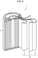
- Fig. 5 is a schematic structural view illustrating an example of the configuration of a nickel-hydrogen rechargeable battery.
- Battery 1 is a nickel-hydrogen rechargeable battery.
- the battery 1 includes a housing 2.
- the housing 2 is a cylindrical case and is made of metal. However, the housing 2 may have any morphology.
- the housing 2 may be a rectangular case.
- the housing 2 may be, for example, a pouch made of an aluminum laminate film.
- the housing 2 may be made of, for example, a resin.
- the housing 2 accommodates a power storage element 10 and an electrolytic solution.
- the power storage element 10 includes a positive electrode 11, a negative electrode 12 and a separator 13.
- the illustrated power storage element 10 is a wound-type element.
- the power storage element 10 is formed by strip-shaped electrodes being wound in a spiral form.
- the power storage element 10 may be, for example, a layered-type element.
- the power storage element 10 may be formed by, for example, layering sheet-shaped electrodes.
- the negative electrode 12 is sheet-shaped, and may have a thickness of, for example, from 10 ⁇ m to 1 mm.
- the negative electrode 12 has a potential that is lower than that of the positive electrode 11.
- the negative electrode includes, for example, a negative electrode current collector and a negative electrode active material.
- Examples of the negative electrode current collector include a nickel mesh.
- Examples of the negative electrode active material include hydrogen absorbing alloys.
- the composition of the hydrogen absorbing alloy is not limited provided that absorption and releasing of hydrogen are possible.
- Examples of hydrogen absorbing alloys include Mm-Ni-Mn-Al-Co-based alloys. "Mm" means a compound of rare earth elements that is called Misch metal.
- the positive electrode 11 is sheet-shaped, and may have a thickness of, for example, from 10 ⁇ m to 1 mm.
- the positive electrode 11 has a potential that is higher than that of the negative electrode 12.
- the positive electrode 11 contains a positive electrode active material.
- the positive electrode active material may include any positive electrode active material. Examples of the positive electrode active material include nickel hydroxide (Ni(OH) 2 ), cobalt hydroxide (Co(OH) 2 ), manganese dioxide, and silver oxide.
- the positive electrode active material is preferably nickel hydroxide.
- the positive electrode 11 may be formed of substantially only a positive electrode active material.
- the positive electrode 11 may further contain a current collector material, a conductive material, a binder and the like.
- the current collector material may include, for example, a porous metal sheet.
- the current collector material is, for example, made of Ni.
- the positive electrode 11 can be formed by applying a positive electrode active material, a conductive material and a binder to a current collector material.
- the conductive material has electron conductivity.
- the conductive material may include any conductive material.
- the conductive material may include, for example, carbon black, Co, or cobalt oxide.
- the amount of the conductive material added may be, for example, from 0.1 parts by mass to 10 parts by mass with respect to 100 parts by mass of the positive electrode active material.
- the binder binds the current collector material and the positive electrode active material, and may include any binder.
- the binder may include, for example, ethylene-vinyl acetate (EVA).
- EVA ethylene-vinyl acetate
- the amount of the binder added may be, for example, from 0.1 parts by mass to 10 parts by mass with respect to 100 parts by mass of the positive electrode active material.
- the separator 13 is sheet-shaped, is disposed between the positive electrode 11 and the negative electrode 12, and physically separates the positive electrode 11 and the negative electrode 12.
- the separator 13 may have a thickness of, for example, from 50 ⁇ m to 500 ⁇ m.
- the separator 13 is porous.
- the separator 13 may include, for example, a stretched porous film or a non-woven fabric.
- the separator 13 is electrically insulating.
- the separator may be formed of, for example, a polyolefin or a polyamide.
- the electrolytic solution is not particularly limited, but is preferably an aqueous electrolytic solution.
- an alkaline aqueous solution or the like can be suitably used as the aqueous electrolytic solution.
- the alkaline aqueous solution contains, for example, water and an alkali metal hydroxide dissolved in water.
- the alkali metal hydroxide may have a concentration of, for example, from 1 mol/L to 20 mol/L.
- alkali metal hydroxides include potassium hydroxide (KOH), sodium hydroxide (NaOH), and lithium hydroxide (LiOH).
- the method of recycling a nickel-hydrogen rechargeable battery uses a used nickel-hydrogen rechargeable battery as at least one of a first tank or a second tank in a water electrolysis apparatus, the water electrolysis apparatus including:
- H 2 gas and O 2 gas having high purities can be extracted safely, reutilizing a used nickel-hydrogen rechargeable battery.
- a water electrolysis apparatus was prepared that had the same configuration as that of the water electrolysis apparatus 20A illustrated in Fig. 1 .
- the following electrolytic solution and batteries were used as the electrolyte solution and the first tank and the second tank, and the positive electrode of the first tank and the negative electrode of the second tank were connected to the power source and the resistor (electronic load).
- water (H 2 O) was supplied from a water supplying pump to the first tank, and water (H 2 O) was supplied from a water supplying pump to the second tank.
- the voltage was maintained by the power source and the resistor such that the potential of the positive electrode of the first tank was higher than the potential of the negative electrode of the second tank. Note that the conditions for maintaining voltage, and specifically, the voltage, average current, time, capacity, input power, quantity of electricity, generated amount of hydrogen, efficiency, distance between electrodes (distance between the positive electrode and the negative electrode) and temperature (temperature of the water electrolysis apparatus overall) are listed in Table 1 and Table 2.
- the water electrolysis apparatus of pattern 1 was used in Experimental Example C1, and the water electrolysis apparatus of pattern 2 was used in Experimental Examples C2 to C5.
- the water electrolysis apparatus of pattern 1 had six power sources, the first tank had six nickel-hydrogen rechargeable batteries, and the second tank had six nickel-hydrogen rechargeable batteries, as is the case with the water electrolysis apparatus 20C illustrated in Fig. 4 .
- Each of the power sources was connected to the positive electrode in one nickel-hydrogen rechargeable battery included in the first tank and the negative electrode in one nickel-hydrogen rechargeable battery included in the second tank, so as to configure a circuit.
- the water electrolysis apparatus had six circuits. The respective circuits were separated by separators. In each circuit, the positive electrode and the negative electrode were also connected to a resistor serving as an electronic load, in addition to being connected to a power source.
- the water electrolysis apparatus of pattern 2 had one power source, the first tank had six nickel-hydrogen rechargeable batteries, and the second tank had six nickel-hydrogen rechargeable batteries, as is the case with the water electrolysis apparatus 20B illustrated in Figs. 2 and 3 .
- the respective positive electrodes of the six nickel-hydrogen rechargeable batteries of the first tank were all connected to the power source, and the respective negative electrodes of the six nickel-hydrogen rechargeable batteries of the second tank were all connected to the power source. Note that the positive electrodes and the negative electrodes were also connected to a resistor serving as an electronic load, in addition to being connected to the power source.
- water (H 2 O) was supplied from a water supplying pump to the first tank, and water (H 2 O) was supplied from a water supplying pump to the second tank.
- the voltage was maintained by the power source and the resistor such that the potential of the positive electrode of the first tank was higher than the potential of the negative electrode of the second tank.
- the conditions for maintaining voltage and specifically, the voltage, average current, time, capacity, input power, quantity of electricity, amount of generated hydrogen, efficiency, immersion height of electrode (the height at which the positive electrode and the negative electrode were immersed in the electrolytic solution), distance between electrodes (distance between the positive electrode and the negative electrode) and temperature (temperature of the water electrolysis apparatus overall) are listed in Table 3.
Landscapes
- Chemical & Material Sciences (AREA)
- Engineering & Computer Science (AREA)
- Chemical Kinetics & Catalysis (AREA)
- Electrochemistry (AREA)
- Organic Chemistry (AREA)
- Metallurgy (AREA)
- Materials Engineering (AREA)
- Manufacturing & Machinery (AREA)
- General Chemical & Material Sciences (AREA)
- Analytical Chemistry (AREA)
- Automation & Control Theory (AREA)
- Inorganic Chemistry (AREA)
- Electrolytic Production Of Non-Metals, Compounds, Apparatuses Therefor (AREA)
- Secondary Cells (AREA)
Applications Claiming Priority (1)
| Application Number | Priority Date | Filing Date | Title |
|---|---|---|---|
| JP2023007608A JP7616254B2 (ja) | 2023-01-20 | 2023-01-20 | 水電解装置、水電解方法、およびニッケル水素蓄電池のリサイクル方法 |
Publications (2)
| Publication Number | Publication Date |
|---|---|
| EP4411024A2 true EP4411024A2 (de) | 2024-08-07 |
| EP4411024A3 EP4411024A3 (de) | 2025-01-01 |
Family
ID=89224525
Family Applications (1)
| Application Number | Title | Priority Date | Filing Date |
|---|---|---|---|
| EP23218137.0A Pending EP4411024A3 (de) | 2023-01-20 | 2023-12-19 | Wasserelektrolysevorrichtung, wasserelektrolyseverfahren und verfahren zur wiederverwertung einer wiederaufladbaren nickel-wasserstoff-batterie |
Country Status (5)
| Country | Link |
|---|---|
| US (1) | US20240247381A1 (de) |
| EP (1) | EP4411024A3 (de) |
| JP (1) | JP7616254B2 (de) |
| KR (1) | KR102939387B1 (de) |
| CN (1) | CN118374818A (de) |
Cited By (1)
| Publication number | Priority date | Publication date | Assignee | Title |
|---|---|---|---|---|
| EP4424875A3 (de) * | 2023-01-20 | 2024-11-13 | Toyota Jidosha Kabushiki Kaisha | Metallrückgewinnungsverfahren und metallrückgewinnungsvorrichtung |
Citations (1)
| Publication number | Priority date | Publication date | Assignee | Title |
|---|---|---|---|---|
| JP2021017628A (ja) | 2019-07-22 | 2021-02-15 | トヨタ自動車株式会社 | 水素ガスの製造装置、水素ガスの製造方法、および水素吸蔵合金 |
Family Cites Families (4)
| Publication number | Priority date | Publication date | Assignee | Title |
|---|---|---|---|---|
| JP6397396B2 (ja) | 2015-12-28 | 2018-09-26 | デノラ・ペルメレック株式会社 | アルカリ水電解方法 |
| JP7709754B2 (ja) * | 2019-11-21 | 2025-07-17 | エヌイー.エム.イー.エスワイエス.エスアールエル | 水電解方法および装置 |
| KR20210074893A (ko) * | 2019-12-12 | 2021-06-22 | 현대자동차주식회사 | 수전해 시스템 및 그 제어방법 |
| CN215050742U (zh) * | 2021-05-25 | 2021-12-07 | 西安交通大学 | 一种退役电池电解水产氢的装置 |
-
2023
- 2023-01-20 JP JP2023007608A patent/JP7616254B2/ja active Active
- 2023-11-30 US US18/524,137 patent/US20240247381A1/en active Pending
- 2023-12-19 EP EP23218137.0A patent/EP4411024A3/de active Pending
- 2023-12-21 KR KR1020230188888A patent/KR102939387B1/ko active Active
-
2024
- 2024-01-15 CN CN202410053744.3A patent/CN118374818A/zh active Pending
Patent Citations (1)
| Publication number | Priority date | Publication date | Assignee | Title |
|---|---|---|---|---|
| JP2021017628A (ja) | 2019-07-22 | 2021-02-15 | トヨタ自動車株式会社 | 水素ガスの製造装置、水素ガスの製造方法、および水素吸蔵合金 |
Cited By (1)
| Publication number | Priority date | Publication date | Assignee | Title |
|---|---|---|---|---|
| EP4424875A3 (de) * | 2023-01-20 | 2024-11-13 | Toyota Jidosha Kabushiki Kaisha | Metallrückgewinnungsverfahren und metallrückgewinnungsvorrichtung |
Also Published As
| Publication number | Publication date |
|---|---|
| JP7616254B2 (ja) | 2025-01-17 |
| JP2024103333A (ja) | 2024-08-01 |
| CN118374818A (zh) | 2024-07-23 |
| US20240247381A1 (en) | 2024-07-25 |
| EP4411024A3 (de) | 2025-01-01 |
| KR102939387B1 (ko) | 2026-03-13 |
| KR20240116359A (ko) | 2024-07-29 |
Similar Documents
| Publication | Publication Date | Title |
|---|---|---|
| US9680193B2 (en) | Electrically rechargeable, metal anode cell and battery systems and methods | |
| JP6774964B2 (ja) | ハイブリッド電池電解器 | |
| US10403930B2 (en) | Electrochemical nanofluid or particle suspension energy conversion and storage device | |
| US9742048B2 (en) | Metal-air battery | |
| US9325037B2 (en) | Hetero-ionic aromatic additives for electrochemical cells comprising a metal fuel | |
| US10411286B2 (en) | Alkali/oxidant battery | |
| CN102844932A (zh) | 电化学电池以及特别是利用电沉积燃料的电池 | |
| US7220501B2 (en) | Integrated hybrid electrochemical device | |
| JP6060335B2 (ja) | 第3電極を備えたリバーシブル燃料電池 | |
| EP4411024A2 (de) | Wasserelektrolysevorrichtung, wasserelektrolyseverfahren und verfahren zur wiederverwertung einer wiederaufladbaren nickel-wasserstoff-batterie | |
| Jindra | Sealed nickel—zinc cells | |
| JP3196605B2 (ja) | 非焼結式ニッケル正極及びその正極を用いたアルカリ蓄電池 | |
| WO2015079689A1 (en) | High capacity alkali/oxidant battery | |
| US20140038000A1 (en) | Flow-Through Metal Battery with Ion Exchange Membrane | |
| EP2001072A2 (de) | Pulverförmige Brennstoffzelle | |
| EP0901179B1 (de) | Alkalische aufladbare Batterie | |
| KR101713401B1 (ko) | 아연공기 2차 전지 및 이의 제조방법 | |
| JP7616255B2 (ja) | 金属の回収方法、及び金属の回収装置 | |
| WO2024084981A1 (en) | Cartridge-type anode unit for zinc-air fuel cell | |
| KR20160150158A (ko) | 니켈-아연 플로우 전지용 전해액 및 이를 포함하는 니켈-아연 플로우 전지 | |
| US20240410060A1 (en) | Water electrolysis method | |
| US20240410059A1 (en) | Water electrolysis method | |
| JPH01134862A (ja) | アルカリ亜鉛蓄電池 | |
| JP2011142048A (ja) | 電解液、マグネシウムイオン2次電池、および電力システム | |
| WO2015045356A1 (en) | Flow-through battery, and method for forming a voltage potential across the flow-through battery |
Legal Events
| Date | Code | Title | Description |
|---|---|---|---|
| PUAI | Public reference made under article 153(3) epc to a published international application that has entered the european phase |
Free format text: ORIGINAL CODE: 0009012 |
|
| STAA | Information on the status of an ep patent application or granted ep patent |
Free format text: STATUS: REQUEST FOR EXAMINATION WAS MADE |
|
| 17P | Request for examination filed |
Effective date: 20240105 |
|
| AK | Designated contracting states |
Kind code of ref document: A2 Designated state(s): AL AT BE BG CH CY CZ DE DK EE ES FI FR GB GR HR HU IE IS IT LI LT LU LV MC ME MK MT NL NO PL PT RO RS SE SI SK SM TR |
|
| PUAL | Search report despatched |
Free format text: ORIGINAL CODE: 0009013 |
|
| AK | Designated contracting states |
Kind code of ref document: A3 Designated state(s): AL AT BE BG CH CY CZ DE DK EE ES FI FR GB GR HR HU IE IS IT LI LT LU LV MC ME MK MT NL NO PL PT RO RS SE SI SK SM TR |
|
| RIC1 | Information provided on ipc code assigned before grant |
Ipc: C25B 15/031 20210101ALI20241126BHEP Ipc: C25B 15/027 20210101ALI20241126BHEP Ipc: H01M 10/54 20060101ALI20241126BHEP Ipc: C25B 15/08 20060101ALI20241126BHEP Ipc: C25B 11/04 20210101ALI20241126BHEP Ipc: C25B 11/02 20210101ALI20241126BHEP Ipc: C25B 9/19 20210101ALI20241126BHEP Ipc: C25B 1/04 20210101AFI20241126BHEP |