EP4408351B1 - Orthopaedietechnisches system und prothesenfuss mit einem solchen - Google Patents
Orthopaedietechnisches system und prothesenfuss mit einem solchen Download PDFInfo
- Publication number
- EP4408351B1 EP4408351B1 EP22798091.9A EP22798091A EP4408351B1 EP 4408351 B1 EP4408351 B1 EP 4408351B1 EP 22798091 A EP22798091 A EP 22798091A EP 4408351 B1 EP4408351 B1 EP 4408351B1
- Authority
- EP
- European Patent Office
- Prior art keywords
- leaf spring
- spring element
- bearing component
- elastomer
- orthopedic system
- Prior art date
- Legal status (The legal status is an assumption and is not a legal conclusion. Google has not performed a legal analysis and makes no representation as to the accuracy of the status listed.)
- Active
Links
Images



Classifications
-
- A—HUMAN NECESSITIES
- A61—MEDICAL OR VETERINARY SCIENCE; HYGIENE
- A61F—FILTERS IMPLANTABLE INTO BLOOD VESSELS; PROSTHESES; DEVICES PROVIDING PATENCY TO, OR PREVENTING COLLAPSING OF, TUBULAR STRUCTURES OF THE BODY, e.g. STENTS; ORTHOPAEDIC, NURSING OR CONTRACEPTIVE DEVICES; FOMENTATION; TREATMENT OR PROTECTION OF EYES OR EARS; BANDAGES, DRESSINGS OR ABSORBENT PADS; FIRST-AID KITS
- A61F2/00—Filters implantable into blood vessels; Prostheses, i.e. artificial substitutes or replacements for parts of the body; Appliances for connecting them with the body; Devices providing patency to, or preventing collapsing of, tubular structures of the body, e.g. stents
- A61F2/50—Prostheses not implantable in the body
- A61F2/60—Artificial legs or feet or parts thereof
- A61F2/66—Feet; Ankle joints
-
- A—HUMAN NECESSITIES
- A61—MEDICAL OR VETERINARY SCIENCE; HYGIENE
- A61F—FILTERS IMPLANTABLE INTO BLOOD VESSELS; PROSTHESES; DEVICES PROVIDING PATENCY TO, OR PREVENTING COLLAPSING OF, TUBULAR STRUCTURES OF THE BODY, e.g. STENTS; ORTHOPAEDIC, NURSING OR CONTRACEPTIVE DEVICES; FOMENTATION; TREATMENT OR PROTECTION OF EYES OR EARS; BANDAGES, DRESSINGS OR ABSORBENT PADS; FIRST-AID KITS
- A61F2/00—Filters implantable into blood vessels; Prostheses, i.e. artificial substitutes or replacements for parts of the body; Appliances for connecting them with the body; Devices providing patency to, or preventing collapsing of, tubular structures of the body, e.g. stents
- A61F2/50—Prostheses not implantable in the body
- A61F2002/5007—Prostheses not implantable in the body having elastic means different from springs, e.g. including an elastomeric insert
- A61F2002/5009—Prostheses not implantable in the body having elastic means different from springs, e.g. including an elastomeric insert having two or more elastomeric blocks
-
- A—HUMAN NECESSITIES
- A61—MEDICAL OR VETERINARY SCIENCE; HYGIENE
- A61F—FILTERS IMPLANTABLE INTO BLOOD VESSELS; PROSTHESES; DEVICES PROVIDING PATENCY TO, OR PREVENTING COLLAPSING OF, TUBULAR STRUCTURES OF THE BODY, e.g. STENTS; ORTHOPAEDIC, NURSING OR CONTRACEPTIVE DEVICES; FOMENTATION; TREATMENT OR PROTECTION OF EYES OR EARS; BANDAGES, DRESSINGS OR ABSORBENT PADS; FIRST-AID KITS
- A61F2/00—Filters implantable into blood vessels; Prostheses, i.e. artificial substitutes or replacements for parts of the body; Appliances for connecting them with the body; Devices providing patency to, or preventing collapsing of, tubular structures of the body, e.g. stents
- A61F2/50—Prostheses not implantable in the body
- A61F2/60—Artificial legs or feet or parts thereof
- A61F2/66—Feet; Ankle joints
- A61F2002/6614—Feet
-
- A—HUMAN NECESSITIES
- A61—MEDICAL OR VETERINARY SCIENCE; HYGIENE
- A61F—FILTERS IMPLANTABLE INTO BLOOD VESSELS; PROSTHESES; DEVICES PROVIDING PATENCY TO, OR PREVENTING COLLAPSING OF, TUBULAR STRUCTURES OF THE BODY, e.g. STENTS; ORTHOPAEDIC, NURSING OR CONTRACEPTIVE DEVICES; FOMENTATION; TREATMENT OR PROTECTION OF EYES OR EARS; BANDAGES, DRESSINGS OR ABSORBENT PADS; FIRST-AID KITS
- A61F2/00—Filters implantable into blood vessels; Prostheses, i.e. artificial substitutes or replacements for parts of the body; Appliances for connecting them with the body; Devices providing patency to, or preventing collapsing of, tubular structures of the body, e.g. stents
- A61F2/50—Prostheses not implantable in the body
- A61F2/60—Artificial legs or feet or parts thereof
- A61F2/66—Feet; Ankle joints
- A61F2002/6614—Feet
- A61F2002/6657—Feet having a plate-like or strip-like spring element, e.g. an energy-storing cantilever spring keel
-
- A—HUMAN NECESSITIES
- A61—MEDICAL OR VETERINARY SCIENCE; HYGIENE
- A61F—FILTERS IMPLANTABLE INTO BLOOD VESSELS; PROSTHESES; DEVICES PROVIDING PATENCY TO, OR PREVENTING COLLAPSING OF, TUBULAR STRUCTURES OF THE BODY, e.g. STENTS; ORTHOPAEDIC, NURSING OR CONTRACEPTIVE DEVICES; FOMENTATION; TREATMENT OR PROTECTION OF EYES OR EARS; BANDAGES, DRESSINGS OR ABSORBENT PADS; FIRST-AID KITS
- A61F2/00—Filters implantable into blood vessels; Prostheses, i.e. artificial substitutes or replacements for parts of the body; Appliances for connecting them with the body; Devices providing patency to, or preventing collapsing of, tubular structures of the body, e.g. stents
- A61F2/50—Prostheses not implantable in the body
- A61F2/60—Artificial legs or feet or parts thereof
- A61F2/66—Feet; Ankle joints
- A61F2002/6614—Feet
- A61F2002/6657—Feet having a plate-like or strip-like spring element, e.g. an energy-storing cantilever spring keel
- A61F2002/6664—Dual structures made of two connected cantilevered leaf springs
Definitions
- the invention relates to an orthopedic system with a leaf spring element and a bearing component supported on a main surface of the leaf spring element, which is fixed to the leaf spring element, as well as a prosthetic foot with such an orthopedic system.
- Leaf spring elements are often used in orthopedic systems to store deformation energy and at the same time to implement force limitations.
- Leaf spring elements of modern design are made of fiber composite materials or have components made of fiber composite materials and are part of complex systems, for example prosthetic feet. In order to use the leaf spring elements effectively, they must be installed in brackets so that other components can be mounted on the leaf spring element. Brackets or other components are attached to a leaf spring element, for example, in a form-fitting manner by screwing the component to be mounted, for example a metal component, onto the leaf spring element.
- Brackets or other components are attached to a leaf spring element, for example, in a form-fitting manner by screwing the component to be mounted, for example a metal component, onto the leaf spring element.
- a leaf spring element can be connected to a support via an adhesive connection, a clamp connection and/or a form-fit connection.
- forms-fit connections using screws holes are drilled into the leaf spring element through which corresponding bolts or screws are then passed and thus connected to the other component. Holes weaken the leaf spring component and therefore cannot be installed everywhere.
- the mechanical properties of fiber composite materials are affected by holes or disturbances in the fiber structure is impaired. In particular in areas of large deformation of the leaf spring elements, add-on parts cannot be installed or are difficult to install.
- the US 6 290 730 B1 shows a foot-ankle prosthesis with an ankle part, a keel part and a bumper part arranged in between.
- the individual components are held together by a holding device.
- the bumper part is made of an elastic polyurethane material.
- the US 2006/069450 A1 discloses a foot prosthesis with a spring element and a fastening element.
- the fastening element is attached to the spring element via screws.
- An elastic element for absorbing pressure forces is arranged between the fastening element and the spring element.
- the elastic element is glued to the fastening element and the spring element.
- the DE 10 2019 101843 A1 relates to a prosthetic foot insert with a leaf spring and a holder.
- a damping element is arranged between the leaf spring and the holder, which is glued to both the holder and the leaf spring.
- the DE 10 2014 006571 B3 discloses a prosthetic foot with a structural component with proximal connection means and a sole-side guide element.
- a spring-damper system is arranged between the structural component and the guide element, which is positively attached to the guide element and the structural component.
- the DE 10 2011 014994 A1 shows a prosthetic foot insert with a roof spring and a base spring.
- Upper connection means are arranged on the roof spring.
- a coupling element is arranged between the roof spring and the base spring.
- the base spring, the roof spring and the coupling element can be formed in one piece.
- the US 5 800 569 A relates to a prosthetic foot with a foot plate and an ankle plate. Between the foot plate and the ankle plate there is an ankle block which is glued to the foot plate and the ankle plate and is made of polyurethane, for example.
- the object of the present invention is therefore to provide an orthopaedic system with a leaf spring element which allows greater design freedom without limiting the durability and load-bearing capacity of the overall system.
- the orthopaedic system with a leaf spring element and a bearing component supported on a main surface of the leaf spring element, which is fixed to the leaf spring element provides that at least one elastomer element is arranged between the bearing component and the main surface of the leaf spring element, which is attached to the leaf spring element and the bearing component in a way that transmits tensile forces and shear forces.
- This increases the design freedom when constructing the orthopedic system or the overall system of which the orthopedic system is a part.
- the bearing component is elastically mounted on the leaf spring element in three rotational and three translational degrees of freedom, whereby only small twists and/or shifts in the respective directions or around the respective axes are possible due to the dimensions of the elastomer element.
- the bearing component has at least one flat support surface, via which the elastomer element is supported on the bearing component and via which it establishes the connection to the leaf spring element.
- the flat support surface enables forces to be introduced over a large area and avoids load peaks from forces that are introduced from the generally rigid bearing component via the elastomer element into the leaf spring element.
- the bearing component is provided with several support surfaces that are spaced apart from one another, so that the bearing component is supported and fastened to several areas of the leaf spring element that are spaced apart from one another.
- the two support surfaces are connected to one another like a bridge by the bearing component and enable optimized introduction of forces and improved load distribution, so that the mechanical properties of the leaf spring element can be optimally utilized.
- the elastomer element is attached to the leaf spring element via a pre-tensioning device.
- the pre-tensioning device can be designed, for example, as a clamp, a clamping system, a belt or a screw connection.
- the pre-tensioning via the pre-tensioning device presses the three components of the system, the leaf spring element, the bearing component and the elastomer element, against each other, which prevents the The assignment of the components to each other is resolved. Noise caused by components hitting each other is avoided, and the user of the orthopaedic system is given a feeling of security through stable force application.
- the at least one elastomer element is glued to the bearing component and/or the leaf spring element.
- the elastomer element is glued to both the bearing component and the leaf spring element, a material-locking coupling of all three elements of the system is ensured in a simple, inexpensive and permanent manner.
- the structure of the leaf spring element is not impaired by the fastening of the bearing component.
- the bearing component can have at least one stop which, in an initial position in which no forces are transmitted from the bearing component to the leaf spring element through the use of the orthopaedic system, is arranged at a distance from a secondary surface or a stop element of the leaf spring element.
- Leaf spring elements have a longitudinal extension and are essentially rectangular in cross-section with two long sides and two short sides opposite one another.
- the surface which is assigned to the long sides is a main surface, the surface which is assigned to the short sides or A secondary surface is assigned to the narrow sides.
- One or more stops can be arranged to the side next to the leaf spring element.
- the distance to the secondary surface enables mobility transversely to the longitudinal extent of the leaf spring element. Compensating movements and displacement movements are made possible and absorbed by the elastomer element.
- a secondary surface can also be formed within the leaf spring element in a bore or in a slot.
- a stop arranged on or in the bearing component can engage in a slot, bore or other recess, whereby without a load, in particular without a load in the main plane, the stop is not in direct contact with the leaf spring element.
- a stop element can be arranged or formed on the leaf spring element, which strikes against a stop or a recess in the bearing component or comes into contact with it when a load limit is exceeded and the relative displacement of the bearing component to the leaf spring element is too great.
- the displacement can be a twisting or a displacement of the bearing component to the leaf spring element.
- stops or stop elements are arranged or formed opposite one another, in particular several stops are arranged laterally next to the leaf spring element and/or the stop element and frame this or these from two or more sides.
- a stop is then preferably made on one of the secondary surfaces or on two stop elements on the leaf spring element.
- a torsion in the transverse plane is in a range between +/- 1 ° and +/- 5 °, in particular +/- 2.5 °. Due to the fact that there is no rigid attachment of the leaf spring element to the bearing component, flexibility in the case of torsional loads is possible, in particular in the frontal plane and the transverse plane, the reference plane for this being the plane in which the main surface of the leaf spring element.
- the connection between the bearing component and the leaf spring element is designed in such a way that a relative movement between the two components is possible to a limited extent. At the same time, a strong deformation of the leaf spring element in all directions is possible to a limited extent without a direct collision between the leaf spring element and the bearing component. Nevertheless, high mechanical forces and loads are transferred from the bearing component to the leaf spring element, whereby the transfer of normal forces from the leaf spring to the bearing block will be the main force transmission device.
- the leaf spring element is made from a fiber composite material
- the bearing component is made in particular from a metal or a metal alloy, in particular a light metal alloy.
- the respective mechanical loads are thus optimally absorbed and transmitted by the respective material.
- the bearing component is designed in particular as a bearing block with a bearing receptacle so that an articulated connection of other components of an overall orthopedic system, in particular another prosthetic component, can be made.
- one or more components can be rigidly or spring-mountedly attached to the bearing component.
- a pyramid adapter can be attached or formed directly to the bearing component or can be coupled to the remaining bearing components via an elastic component.
- the connection of other components to the bearing component in particular a lateral and/or proximal connection, can also be designed to be non-rotatable or torsionally rigid, which is understood to mean both a one-piece design and a multi-part design.
- the bearing component is arranged in the middle third between the ends of the leaf spring element, whereby a force introduction can be realized in those areas of the leaf spring element, which are designed to be particularly flexible when the rest of the leaf spring element is supported at its ends.
- the introduction of force in areas with high deformation allows the spring properties of the leaf spring element to be used effectively and a fine response is provided when forces are introduced from the bearing component via the elastomer element into the leaf spring element.
- the elastomer element or elements preferably consist of a permanently elastic material, in particular of a polyurethane elastomer, which advantageously has a Shore A hardness between A40 and A80, preferably between A50 and A70 and particularly preferably between A55 and A65.
- a permanently elastic material in particular of a polyurethane elastomer, which advantageously has a Shore A hardness between A40 and A80, preferably between A50 and A70 and particularly preferably between A55 and A65.
- the use of other elastomers that are permanently elastic and durable over the service life is also possible.
- the invention relates in particular to a prosthetic foot insert with an orthopedic system as described above.
- a prosthetic foot insert with an orthopedic system as described above.
- the prosthetic foot is more flexible for the prosthetic user, since the prosthetic foot is rotatoryly flexible in the frontal plane via the connection of the bearing component with the interposition of at least one elastomer element.
- the use of the prosthetic foot during rotation is also made easier, since there is rotatory flexibility in the transverse plane.
- FIG. 1 An exploded view of an orthopedic system with a bearing component 600 in the form of a bearing block is shown, which has a bearing holder 640 with associated bearing shells 641. An axis is inserted into the bearing holder 640, around which the bearing component 600 can be pivoted.
- the bearing component 600 can, for example, be pivotably attached to a carrier, which in turn has a proximal fastening device for attachment to another prosthetic component, for example as part of a prosthetic foot, which is attached to an ankle joint or to a lower leg tube or a lower leg shaft.
- the bearing component 600 is constructed like a bridge and has two flat support surfaces on the underside, which will be explained in more detail later.
- the leaf spring element 40 made of a fiber composite material is shown below the bearing component 600.
- the leaf spring element 40 has a substantially rectangular cross-section, with a top and a bottom as main surface 41 and two short side edges as secondary surfaces 43.
- the Leaf spring element 40 is essentially straight, but can also have a slight curvature or a wave-like shape.
- a heel element 45 can be fixed to the underside of the leaf spring element 40.
- cushion elements or coupling devices for connecting further components of an overall system can be attached to the underside and/or top of the leaf spring element 40.
- two elastomer elements 71, 72 are arranged between the top side on the main surface 41 of the leaf spring element 40 and the bottom side with the support surfaces of the bearing component 600, which lie flat on both the leaf spring element 40 and the bearing component 600.
- Stops 630 are located on the side next to the leaf spring element 40 and next to the elastomer elements 71, 72 and are formed on the bearing component 600.
- the stops 630 are downwardly projecting projections that ensure a lateral limitation of a displacement of the bearing component 600 relative to the leaf spring element 40.
- the elastomer elements 71, 72 are attached to the leaf spring element 40 and the bearing component 600 at a distance from one another, in particular glued or welded.
- Alternative fastening types for example a positive fastening in addition or as an alternative thereto, are provided, provided that they enable a transmission of shear forces and tensile forces to the respective elastomer elements 71, 72.
- stops 630 As an alternative to the total of four stops 630, only two stops 630 arranged diagonally, opposite one another or one side behind the other can be arranged or formed.
- a further alternative is that instead of a lateral arrangement and a possible stop of the stops 630 on the secondary surfaces 43, a stop element is arranged or formed on the surface of the leaf spring element 40, which is framed by two or more stops and initially allows a relative displacement of the leaf spring element 40 relative to the bearing component 600 and then limits it when a limit load is present. This limits excessive deformation of the elastomer elements 71, 72 and the maximum displacement from the Bearing component 600 to the leaf spring element 40.
- Such a movement restriction can also be achieved by forming or introducing a slot, a recess or an indentation in the leaf spring element 40, into which a corresponding element, for example a pin, a tab or a pin, is inserted and comes into contact with the leaf spring element 40 after overcoming elastic restoring forces of the elastomer elements 71, 72.
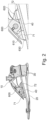
- FIG. 2 sectional views of a prosthetic foot with an orthopedic system described above are shown.
- the bearing component 600 described above can be seen as well as the two elastomer elements 71, 72 and the leaf spring element 40, on the top of which the bearing component 600 with the stops 630 is arranged.
- the respective flat support surfaces 610, 620 are formed on the underside of the bearing component 600, which run essentially parallel to the main surface 41 of the leaf spring element 40.
- the elastomer elements 71, 72 are glued to both the leaf spring element 40 and the bearing component 600.
- cushion elements 30 are arranged and fastened to the top and bottom of the leaf spring element 40.
- the lower cushion element 30 is supported on a base spring 20, which is coupled or connected to the leaf spring element 40 in the forefoot area.
- the upper cushion element 30 is supported on a carrier 10, on which in turn the bearing component 600 is pivotably mounted about the pivot axis in the bearing receptacle 640.
- a pyramid adapter for fastening the prosthetic foot to a proximal prosthetic component is attached to the top of the carrier 10.
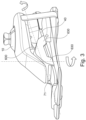
- the prosthetic foot is according to Figure 2 shown in a perspective overall view.
- the carrier 10 is pre-tensioned relative to the base spring 20 via a tensioning device and clamps the leaf spring element 40 between the two cushion elements 30.
- the upper cushion element 30 enables a slight displacement of the carrier 10 relative to the leaf spring element 40 in the heel area or in the rear area.
- the elastic mounting and the The arrangement of the stops 630 spaced apart from the secondary surfaces 43 of the leaf spring element 40 allows a controlled, slight rotation both about the axis perpendicular to the transverse plane and about an axis perpendicular to the frontal plane.
- a rotation about an axis perpendicular to the sagittal plane is also possible, which runs essentially parallel to the axis of the bearing holder 640.
- a uniform load will be applied to both the rear and the front elastomer elements 71, 72, so that rotation about this degree of freedom is possible, but practically not relevant.
- the mounting via the elastomer elements 71, 72 also allows a displacement in three translational degrees of freedom.
- FIG. 5 a frontal view of the bearing component 600 with the front, flat contact surface 610, the two lateral stops 630 and the elastomer elements 71, 72 between the leaf spring element 40 and the contact surface 610 can be seen.
- FIG 6 in a bottom view, the bearing component 600 with the two flat support surfaces 610, 620 for the two elastomer elements 71, 72 arranged at a distance from each other can be seen.
- the stops 630 are positioned to the right and left or medial and lateral to the side edges of the elastomer elements 71, 72 at a distance from them.
- the elastomer elements 71, 72 extend over the entire width of the leaf spring element 40 and thus enable a full-surface, uniform force introduction to the leaf spring element 40 over its entire width due to the elastic properties. Due to the large-area introduction of forces, load peaks on the leaf spring element 40 are avoided, the mechanical load is reduced and damage is prevented.
- the Bearing component 600 is constructed like a bridge, whereby a free space or a gap is created between the two elastomer elements 71, 72, so that in the case of a central load via the bearing holder 640, the force introduction along the longitudinal extension of the leaf spring element 40 is divided into two object areas or surfaces.
- FIG. 7 and 8 Variants of the invention are shown in which two elastomer elements 71, 710, 72, 720 are arranged between the support surfaces 610, 620 and the leaf spring element 40.
- the respective elastomer elements 71, 710, 72, 720 can be attached to the respective component, i.e. the bearing component 600 and the leaf spring element 40, in different ways.
- the elastomer element 710, 720 arranged on the bearing component 600 on the contact surface is positively attached to the bearing component 600, while the other elastomer element 71, 72 is glued to the surface of the leaf spring element 40.
- the upper elastomer element 710, 720 can have side walls or a recess into which the lower elastomer element 71, 72 can be inserted or placed against it, so that displacement and/or rotation of the elastomer elements 71, 710, 72, 720 relative to one another is not possible or only possible in certain directions. Depending on the shape of the elastomer elements, rotation about an axis perpendicular to the transverse plane may be possible. Rotation and tilting of the bearing component 600 relative to the leaf spring element 40 is also possible due to the elastic properties of the elastomer elements 71, 710, 72, 720.
- both elastomer elements 71, 710 can also be glued to the respective component.
- the arrangement of several elastomer elements 71, 710; 72, 720 between the bearing component 600 and the leaf spring element 40 increases the design freedom when designing the elastic properties.
- pre-tensioning devices 60 in the form of belts are arranged on both the bearing component 600 and the leaf spring element 40 in the illustrated embodiment.
- the pre-tensioning devices 60 can be flexible and rigid or elastic. They are guided in guides on the bearing component 600 and underneath the leaf spring element 40 and cause a pre-tension of the bearing component 600 in the direction of the leaf spring element 40. As a result, the elastomer elements 71, 710, 72, 720 arranged in pairs are pressed against one another and held together permanently.
- the pre-tensioning device 60 can also be designed to be detachable, so that the pre-tensioning device 60 is released and re-attached to replace elastomer elements 71, 710, 72, 720.
- the pre-tensioning device 60 can also be designed differently, for example as a screw connection.
- the lateral stops 630 are positioned at a distance from both the leaf spring element 40 and the lower elastomer element 71 attached to the leaf spring element 40.
- the upper elastomer element 710 arranged on the bearing component 600 fills the gap or space between the inside of the stop 630 and the lower elastomer element 71, so that an additional lateral guide is provided.
- the side walls of the upper elastomer element 710 can also leave a free space to the inner surfaces of the respective stop 630 or only one stop 630.
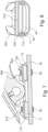
- FIG. 9 three representations of a further variant are shown, in which the leaf spring element 40 is embedded between two elastomer elements 71, 715.
- One elastomer element 71 is arranged between the bearing component 600 on the support surface and the top of the leaf spring element 40
- the other elastomer element 715 is arranged below the leaf spring element 40 and supports it against a pretensioning device 60, which in the illustrated embodiment is designed as a clamping bracket that is releasably fixed to the bearing component 600 via two screws.
- the clamping bracket extends below the leaf spring element 40 and is U-shaped. Internal threads for receiving the screws are arranged in the two upwardly projecting legs of the clamping bracket.
- the leaf spring element 40 is guided laterally through the two upwardly projecting legs, whereby a lateral distance can exist between the inner sides of the upwardly projecting legs and the leaf spring element 40 in order to enable rotation and displacement relative to the bearing component 600.
- the two screws are guided through through holes in the bearing component 600, by loosening or tightening the screws, the preload of the elastomer components 71, 715 can be individually varied.
- a bottom view of the orthopedic system as part of a prosthetic foot is shown, from which it can be seen that the respective clamping bracket extends over the entire width below the leaf spring element 40.
- two pre-tensioning devices 60 spaced apart from one another in the longitudinal extension of the leaf spring element 40 are arranged on the bearing component 600 and enable force to be introduced into two spaced-apart areas of the leaf spring element 40.
- the pre-tensioning can be continuously adjusted.
- the pre-tensioning device 60 can also be designed as a strip-shaped plate.
- Other force transmission devices can also be part of the preloading device 60 in order to preload the leaf spring element 40 against the bearing component 600 with at least one elastomer element 71 arranged therebetween and to clamp them together.
- the leaf spring element is advantageously supported on other components or the floor at both of its end areas, so that overall a four-point bearing is achieved with a bearing at the two end areas and a force introduction at two spaced-apart force introduction areas provided between the bearing points at the end areas.
- the bearing component 600 is designed as a bearing block with a bearing receptacle 640 between two support surfaces 610, 620, positioning the bearing receptacle 640 on the leaf spring element 40 in the middle of the spring length or within the middle fifth of the leaf spring element 40 is advantageous. This ensures that the leaf spring element 40 is evenly loaded.
- the positioning of the bearing receptacle 640 is shifted somewhat further in the anterior direction due to the greater total length of the base spring 20 compared to the leaf spring element 40 and the non-central arrangement of the leaf spring element 40 above the base spring 20.
- the bearing seat 640 is located slightly behind the center compared to the overall length, but still within the middle fifth of the overall length of the prosthetic foot.
Landscapes
- Health & Medical Sciences (AREA)
- Transplantation (AREA)
- Biomedical Technology (AREA)
- Cardiology (AREA)
- Oral & Maxillofacial Surgery (AREA)
- Engineering & Computer Science (AREA)
- Orthopedic Medicine & Surgery (AREA)
- Heart & Thoracic Surgery (AREA)
- Vascular Medicine (AREA)
- Life Sciences & Earth Sciences (AREA)
- Animal Behavior & Ethology (AREA)
- General Health & Medical Sciences (AREA)
- Public Health (AREA)
- Veterinary Medicine (AREA)
- Prostheses (AREA)
Description
- Die Erfindung betrifft ein orthopädietechnisches System mit einem Blattfederelement und einer auf einer Hauptfläche des Blattfederelementes abgestützten Lagerungskomponente, die an dem Blattfederelement festgelegt ist sowie einen Prothesenfuß mit einem solchen orthopädietechnischen System.
- Blattfederelemente werden häufig in orthopädietechnischen Systemen eingesetzt, um Verformungsenergien zu speichern und gleichzeitig Kraftbegrenzungen zu verwirklichen. Blattfederelemente der modernen Bauart bestehen aus Faserverbundwerkstoffen oder weisen Komponenten aus Faserverbundwerkstoffen auf und sind Teil komplexer Systeme, beispielsweise von Prothesenfüßen. Um die Blattfederelemente effektiv einzusetzen, müssen diese in Halterungen eingebaut werden, damit weitere Komponenten an dem Blattfederelement gelagert werden können. Die Befestigung von Halterungen oder anderen Bauteilen an einem Blattfederelement erfolgt beispielsweise formschlüssig, indem das zu montierende Bauteil, beispielsweise ein Metallbauteil, an dem Blattfederelement angeschraubt wird. Eine solche Lösung ist in der
US 10 390 974 B2 EP 3 128 958 B1 beschrieben. - Aus der
WO 2020/1523 41 A1 ist bekannt, dass ein Blattfederelement über eine Klebeverbindung, eine Klemmverbindung und/oder eine Formschlussverbindung mit einem Träger verbunden sein kann. Bei Formschlussverbindungen über Schrauben werden Bohrungen in das Blattfederelement eingebracht, durch die dann entsprechende Bolzen oder Schrauben hindurchgeführt und somit der weiteren Komponente verbunden werden. Bohrungen schwächen die Blattfederkomponente und sind daher nicht überall anzubringen, insbesondere Faserverbundwerkstoffe werden in ihren mechanischen Eigenschaften durch Bohrungen oder Störungen in der Faserstruktur beeinträchtigt. Insbesondere in Bereichen großer Deformationen der Blattfederelemente lassen sich Anbauteile nicht oder nur schwer montieren. - Orthopädietechnische Systeme nach dem Oberbegriff des Anspruchs 1 wurden in folgenden Dokumenten offenbart.
- Die
US 6 290 730 B1 zeigt eine Fuß-Knöchel-Prothese mit einem Knöchelteil, einem Kielteil und einem dazwischen angeordneten Stoßfängerteil. Die einzelnen Komponenten werden durch eine Haltevorrichtung zusammengehalten. Das Stoßfängerteil ist aus einem elastischen Polyurethan-Material gebildet. - Die
US 2006/069450 A1 offenbart eine Fußprothese mit einem Federelement und einem Befestigungselement. Das Befestigungselement ist über Schrauben an dem Federelement befestigt. Zwischen dem Befestigungselement und dem Federelement ist ein elastisches Element zum Absorbieren von Druckkräften angeordnet. Das elastische Element ist mit dem Befestigungselement und dem Federelement verklebt. - Die
DE 10 2019 101843 A1 betrifft einen Prothesenfußeinsatz mit einer Blattfeder und einem Halter. Zwischen der Blattfeder und dem Halter ist ein Dämpferelement angeordnet, das sowohl mit dem Halter als auch mit der Blattfeder verklebt ist. - Die
DE 10 2014 006571 B3 offenbart einen Prothesenfuß mit einem Strukturbauteil mit proximalen Anschlussmitteln und einem sohlenseitigen Führungselement. Zwischen dem Strukturbauteil und dem Führungselement ist ein Feder-Dämpfer-System angeordnet, das formschlüssig an dem Führungselement und dem Strukturbauteil befestigt ist. - Die
DE 10 2011 014994 A1 zeigt einen Prothesenfußeinsatz mit einer Dachfeder und einer Basisfeder. An der Dachfeder sind obere Anschlussmittel angeordnet. Zwischen der Dachfeder und der Basisfeder ist ein Koppelelement angeordnet. Die Basisfeder, die Dachfeder und das Koppelelement können einstückig ausgebildet sein. - Die
US 5 800 569 A betrifft einen Prothesenfuß mit einer Fußplatte und einer Knöchelplatte. Zwischen der Fußplatte und der Knöchelplatte ist ein Knöchelblock angeordnet, der an der Fußplatte und der Knöchelplatte festgeklebt ist und beispielsweise aus Polyurethan gebildet ist. - Aufgabe der vorliegenden Erfindung ist es daher ein orthopädietechnisches System mit einem Blattfederelement bereitzustellen, das eine größere Gestaltungsfreiheit ohne Einschränkung der Haltbarkeit und Belastbarkeit des Gesamtsystems ermöglicht.
- Erfindungsgemäß wird diese Aufgabe durch ein orthopädietechnisches System mit den Merkmalen des Hauptanspruches und einen Prothesenfuß mit einem solchen orthopädietechnischen System gelöst. Vorteilhafte Ausgestaltungen und Weiterbildungen der Erfindung sind in der Beschreibung, den Unteransprüchen sowie den Figuren offenbart.
- Das orthopädietechnische System mit einem Blattfederelement und einer auf einer Hauptfläche des Blattfederelementes abgestützten Lagerungskomponente, die an dem Blattfederelement festgelegt ist, sieht vor, dass zwischen der Lagerungskomponente und der Hauptfläche des Blattfederelementes zumindest ein Elastomerelement angeordnet ist, das Zugkräfte und Scherkräfte übertragend an dem Blattfederelement und der Lagerungskomponente befestigt ist. Zwischen der Lagerungskomponente und dem Blattfederelement ist somit eine elastische Anbindung vorhanden, die eine Relativbewegung zwischen dem Blattfederelement und der Lagerungskomponente ermöglicht. Dadurch ist es möglich, trotz einer sicheren und belastbaren Zuordnung der Lagerungskomponente an dem Blattfederelement auch in Bereichen hoher Verformungen des Blattfederelementes eine Anordnung und Positionierung der Lagerungskomponente zu erreichen. Die Befestigung der Lagerungskomponente an dem Blattfederelement in der Art und Weise, dass auch Zugkräfte und Scherkräfte, die über die Lagerungskomponente auf das Blattfederelement aufgebracht werden, sicher und dauerhaft auf das Blattfederelement übertragen werden können, ermöglicht eine nahezu beliebige Positionierung der Lagerungskomponente auf dem Blattfederelement, ungeachtet der Verformungssituation des Blattfederelementes bei einer Benutzung des orthopädietechnischen Systems. Dadurch erhöht sich der Gestaltungsfreiraum bei der Konstruktion des orthopädietechnischen Systems oder des Gesamtsystems, von dem das orthopädietechnische System ein Teil ist. Die Lagerungskomponente ist in drei rotatorischen und drei translatorischen Freiheitsgraden elastisch auf dem Blattfederelement gelagert, wobei aufgrund der Abmessungen des Elastomerelementes jeweils nur geringe Verdrehungen und/oder Verschiebungen in die jeweiligen Richtungen bzw. um die jeweiligen Achsen möglich sind.
- In einer Ausgestaltung weist die Lagerungskomponente zumindest eine ebene Abstützfläche auf, über die sich das Elastomerelement auf der Lagerungskomponente abstützt und darüber die Verbindung zu dem Blattfederelement herstellt. Die ebene Abstützfläche ermöglicht eine großflächige Einleitung von Kräften und vermeidet Belastungsspitzen von Kräften, die von der in der Regel starren Lagerungskomponente über das Elastomerelement in das Blattfederelement eingeleitet werden.
- In einer Weiterbildung ist die Lagerungskomponente mit mehreren, voneinander beabstandeten Abstützflächen versehen, sodass eine Lagerung und Befestigung der Lagerungskomponente an mehreren, voneinander beabstandeten Bereichen des Blattfederelementes erfolgt. Die beiden Abstützflächen werden brückenartig durch die Lagerungskomponente miteinander verbunden und ermöglichen eine optimierte Einleitung von Kräften und eine verbesserte Lastverteilung, sodass die mechanischen Eigenschaften des Blattfederelementes optimal ausgenutzt werden können.
- Das Elastomerelement ist in einer Ausgestaltung über eine Vorspanneinrichtung an dem Blattfederelement befestigt. Die Vorspanneinrichtung kann beispielsweise als eine Klammer, ein Klemmsystem, ein Gurt oder eine Verschraubung ausgebildet sein. Durch die Vorspannung über die Vorspanneinrichtung werden die drei Komponenten des Systems, das Blattfederelement, die Lagerungskomponente und das Elastomerelement, aneinander gepresst, wodurch verhindert wird, dass die Zuordnung der Komponenten zueinander aufgelöst wird. Eine Geräuschentwicklung durch Aufeinanderschlagen von Bauteilen wird vermieden, darüber hinaus wird dem Nutzer des orthopädietechnischen Systems ein sicheres Gefühl durch eine stabile Krafteinleitung vermittelt.
- Das zumindest eine Elastomerelement ist in einer Ausgestaltung mit der Lagerungskomponente und/oder dem Blattfederelement verklebt. Bei einer Verklebung des Elastomerelementes sowohl mit der Lagerungskomponente als auch mit dem Blattfederelement wird eine stoffschlüssige Kopplung aller drei Elemente des Systems auf eine einfache und preiswerte sowie dauerhafte Art und Weise gewährleistet. Eine Beeinträchtigung der Struktur des Blattfederelementes erfolgt durch die Befestigung der Lagerungskomponente nicht. Gleiches gilt für eine Verklebung des Elastomerelementes mit dem Blattfederelement und einer Kopplung und Befestigung des Elastomerelementes mit der Lagerungskomponente über eine andere Befestigungseinrichtung oder ein Befestigungselement, beispielsweise durch Schrauben. Es besteht auch die Möglichkeit, durch Klemmen über Klemmeinrichtungen eine Befestigung des Blattfederelementes an der Lagerungskomponente unter Zwischenschaltung des Elastomerelementes zu bewirken. Auch wenn eine Verschraubung mit einem Durchgangsloch durch das Blattfederelement erfolgt, wird über die Zwischenschaltung des Elastomerelementes die mechanische Belastung einer Kraftübertragung über die Lagerungskomponente verringert und ein Vorteil hinsichtlich der Gestaltungsfreiheit und Haltbarkeit des orthopädietechnischen Systems erreicht.
- Die Lagerungskomponente kann zumindest einen Anschlag aufweisen, der in einer Ausgangsstellung, in der keine Kräfte durch die Benutzung des orthopädietechnischen Systems von der Lagerungskomponente auf das Blattfederelement übertragen werden, beanstandet zu einer Nebenfläche oder einem Anschlagelement des Blattfederelementes angeordnet ist. Blattfederelemente weisen eine Längserstreckung auf und sind im Querschnitt zu der Längserstreckung im Wesentlichen rechteckig mit zwei langen Seiten und zwei einander gegenüberliegenden Kurzseiten ausgebildet. Die Oberfläche, die den langen Seiten zugeordnet ist, ist eine Hauptfläche, die Oberfläche, die den kurzen Seiten oder Schmalseiten zugeordnet ist, ist eine Nebenfläche. Ein Anschlag oder mehrere Anschläge können seitlich neben dem Blattfederelement angeordnet sein. Durch den Abstand zu der Nebenfläche ist eine Beweglichkeit quer zu der Längserstreckung des Blattfederelementes möglich. Ausgleichsbewegungen und Verschiebebewegungen werden über das Elastomerelement ermöglicht und aufgefangen. Die Verformungen des Elastomerelementes werden bis zu einem Kontakt des Anschlages mit dem Blattfederelement zugelassen. Eine Nebenfläche kann auch innerhalb des Blattfederelementes in einer Bohrung oder in einem Schlitz ausgebildet sein. So kann ein an oder in der Lagerungskomponente angeordneter Anschlag in einen Schlitz, eine Bohrung oder eine andere Ausnehmung eingreifen, wobei ohne eine Belastung, insbesondere ohne eine Belastung in der Hauptebene, der Anschlag nicht in unmittelbaren Kontakt mit dem Blattfederelement steht. Alternativ oder ergänzend zu einem direkten Kontakt mit dem Blattfederelement kann an dem Blattfederelement ein Anschlagselement angeordnet oder ausgebildet sein, das gegen einen Anschlag oder eine Ausnehmung der Lagerungskomponente anschlägt oder in Kontakt damit tritt, wenn eine Belastungsgrenze beschritten wird und die Relativverlagerung von Lagerungskomponente zu Blattfederelement zu groß ist. Die Verlagerung kann eine Verdrehung oder eine Verschiebung der Lagerungskomponente zu dem Blattfederelement sein.
- In einer Ausgestaltung sind mehrere Anschläge oder Anschlagelemente einander gegenüberliegend angeordnet oder ausgebildet, insbesondere sind mehrere Anschläge seitlich neben dem Blattfederelement und/oder dem Anschlagelement angeordnet und rahmen dieses oder diese von zwei oder mehr Seiten ein. Ein Anschlag erfolgt dann bevorzugt an einer der Nebenflächen oder an zwei Anschlagelementen an dem Blattfederelement.
- In einer vorteilhaften Ausgestaltung ist vorgesehen, dass eine Torsion in der Transversalebene in einem Bereich zwischen +/- 1 ° und +/- 5°, insbesondere +/- 2,5° beträgt. Aufgrund des Umstandes, dass keine starre Befestigung des Blattfederelementes an der Lagerungskomponente vorhanden ist, wird eine Nachgiebigkeit bei Torsionsbelastungen insbesondere in der Frontalebene und der Transversalebene ermöglicht, wobei die Bezugsebene hierfür die Ebene ist, in der die Hauptfläche des Blattfederelementes liegt. Die Verbindung zwischen der Lagerungskomponente und dem Blattfederelement wird dadurch so ausgelegt, dass eine Relativbewegung zwischen den beiden Bauteilen in einem begrenzten Ausmaß möglich ist. Gleichzeitig wird eine starke Verformung des Blattfederelementes in allen Richtungen in einem begrenzten Umfang möglich, ohne dass es zu einer direkten Kollision zwischen dem Blattfederelement und der Lagerungskomponente kommt. Dennoch werden hohe mechanische Kräfte und Belastungen von der Lagerungskomponente auf das Blattfederelement übertragen, wobei die Übertragung von Normalkräften von der Blattfeder auf den Lagerbock die hauptsächliche Kraftübertragungseinrichtung darstellen wird.
- Vorteilhafterweise ist das Blattfederelement aus einem Faserverbundwerkstoff hergestellt, die Lagerungskomponente ist insbesondere aus einem Metall oder einer Metalllegierung, insbesondere einer Leichtmetalllegierung hergestellt. Damit werden die jeweiligen mechanischen Belastungen durch das jeweilige Material optimal aufgenommen und weitergeleitet.
- Die Lagerungskomponente ist insbesondere als ein Lagerbock mit einer Lageraufnahme ausgebildet, sodass eine gelenkige Anbindung weiterer Komponenten eines orthopädietechnischen Gesamtsystems, insbesondere einer weiteren Prothesenkomponente, erfolgen kann. Statt einer gelenkigen Anbindung weiterer Komponenten an die Lagerungskomponente kann eine oder können mehrere Komponenten starr oder federnd an der Lagerungskomponente befestigt sein. Ein Pyramidenadapter kann direkt an der Lagerungskomponente befestigt oder ausgebildet sein oder über ein elastisches Bauteil mit der übrigen Lagerungskomponente gekoppelt sein. Die Verbindung anderer Bauteile mit der Lagerungskomponente, insbesondere eine seitliche und/oder proximale Anbindung, kann auch drehfest oder drehstarr ausgeführt sein, worunter sowohl eine einstückige Ausgestaltung als auch eine mehrteilige Ausgestaltung zu verstehen ist.
- Die Lagerungskomponente ist in einer Ausgestaltung in dem mittleren Drittel zwischen den Enden des Blattfederelementes angeordnet, wodurch sich eine Krafteinleitung in denjenigen Bereichen des Blattfederelementes verwirklichen lässt, die besonders nachgiebig ausgebildet sind, wenn die übrige Lagerung des Blattfederelementes an dessen Enden stattfindet. Die Krafteinleitung in Bereichen mit hoher Deformation lässt es zu, dass die Federeigenschaften des Blattfederelementes gut ausgenutzt werden und ein feines Ansprechen bei Einleitung von Kräften von der Lagerungskomponente über das Elastomerelement in das Blattfederelement gegeben ist.
- Das Elastomerelement oder die Elastomerelemente bestehen bevorzugt aus einem dauerelastischen Material, insbesondere aus einem Polyurethan-Elastomer, das vorteilhafterweise eine Shore-Härte A zwischen A40 und A80, bevorzugt zwischen A50 und A70 und besonders bevorzugt zwischen A55 und A65 aufweist. Die Verwendung anderer, über die Einsatzdauer dauerhaft elastischer und dauerfester Elastomere ist ebenfalls möglich.
- Die Erfindung betrifft insbesondere einen Prothesenfußeinsatz mit einem orthopädietechnischen System, wie es oben beschrieben worden ist. Mit einer solchen Ausgestaltung ist es möglich, die Reduktion der Belastung des Blattfederelementes aufgrund einer großflächigen Lasteinleitung über die gesamte Breite der Hauptseite zu ermöglichen. Belastungsspitzen durch eine direkte Kopplung von der Lagerungskomponente auf dem Blattfederelement werden vermieden. Darüber hinaus stellt sich eine erhöhte Flexibilität des Prothesenfußes für den Prothesennutzer ein, da sich eine rotatorische Nachgiebigkeit des Prothesenfußes in der Frontalebene über die Anbindung der Lagerungskomponente unter Zwischenschaltung zumindest eines Elastomerelementes ergibt. Auch die Nutzung des Prothesenfußes bei Drehungen wird erleichtert, da eine rotatorische Nachgiebigkeit in der Transversalebene vorhanden ist.
- Nachfolgend werden Ausführungsbeispiele der Erfindung anhand der Figuren näher erläutert. Gleiche Bezugszeichen bezeichnen gleiche Komponenten. Es zeigen:
-
Figur 1 - ein orthopädietechnisches System in Explosionsdarstellung; -
Figur 2 - schematische Schnittdarstellungen eines Prothesenfußes; -
Figur 3 - eine schematische Gesamtdarstellung eines Prothesenfußes; -
Figur 4 - eine unten Ansicht auf eine orthopädietechnische System; -
Figur 5 - eine Frontalansicht auf ein orthopädietechnisches System; -
Figur 6 - eine unten Ansicht auf eine Lagerungskomponente; -
Figur 7 - eine vergrößerte Schnittdarstellung durch eine Variante; -
Figur 8 - eine Querschnittsansicht durch die Variante gemäßFigur 7 ; sowie -
Figur 9 - drei Ansichten einer geklemmten Variante. - In der
Figur 1 ist in einer Explosionsdarstellung ein orthopädietechnisches System mit einer Lagerungskomponente 600 in Gestalt eines Lagerbockes dargestellt, das eine Lageraufnahme 640 mit dazugehörigen Lagerschalen 641 aufweist. In der Lageraufnahme 640 ist eine Achse eingeführt, um die herum die Lagerungskomponente 600 verschwenkt werden kann. Die Lagerungskomponente 600 kann beispielsweise an einem Träger schwenkbar befestigt sein, der wiederum eine proximale Befestigungseinrichtung zur Festlegung an einer weiteren Prothesenkomponente aufweist, beispielsweise als Teil eines Prothesenfußes, der an einem Knöchelgelenk oder an einem Unterschenkelrohr oder einem Unterschenkelschaft befestigt wird. Die Lagerungskomponente 600 ist brückenartig aufgebaut und weist auf der Unterseite zwei ebene Abstützflächen auf, die später näher erläutert werden. - Unterhalb der Lagerungskomponente 600 ist ein Blattfederelement 40 aus einem Faserverbundwerkstoff dargestellt. Das Blattfederelement 40 weist einen im Wesentlichen rechteckigen Querschnitt auf, mit einer Oberseite und einer Unterseite als Hauptfläche 41 und zwei kurzen Seitenkanten als Nebenflächen 43. Das Blattfederelement 40 ist im Wesentlichen geradlinig ausgebildet, kann aber auch eine leichte Krümmung oder eine wellenartige Formgebung aufweisen. An der Unterseite des Blattfederelementes 40 ist ein Fersenelement 45 festlegbar. Alternativ zu dem Fersenelement 45 können Polsterelemente oder Kopplungseinrichtungen zur Anbindung weiterer Komponenten eines Gesamtsystems an der Unterseite und/oder Oberseite des Blattfederelementes 40 befestigt sein.
- Zwischen der Oberseite auf der Hauptfläche 41 des Blattfederelementes 40 und der Unterseite mit den Abstützflächen der Lagerungskomponente 600 sind in dem dargestellten Ausführungsbeispiel zwei Elastomerelemente 71, 72 angeordnet, die flächig sowohl auf dem Blattfederelement 40 als auch an der Lagerungskomponente 600 anliegen. Seitlich neben dem Blattfederelement 40 und neben den Elastomerelementen 71, 72 befinden sich Anschläge 630, die an der Lagerungskomponente 600 ausgebildet sind. Die Anschläge 630 sind nach unten ragende Vorsprünge, die eine seitliche Begrenzung einer Verlagerung der Lagerungskomponente 600 relativ zu dem Blattfederelement 40 gewährleisten. Die Elastomerelemente 71, 72 sind beanstandet zueinander an dem Blattfederelement 40 und der Lagerungskomponente 600 befestigt, insbesondere verklebt oder verschweißt. Alternative Befestigungsarten, beispielsweise eine formschlüssige Befestigung zusätzlich oder alternativ dazu, sind vorgesehen, sofern sie eine Übertragung von Scherkräften und Zugkräften auf die jeweiligen Elastomerelemente 71, 72 ermöglichen.
- Alternativ zu den insgesamt vier Anschlägen 630 können auch nur zwei diagonal, gegenüberliegende oder einseitig hintereinander angeordnete Anschläge 630 angeordnet oder ausgebildet sein. Eine weitere Alternative besteht darin, dass statt einer seitlichen Anordnung und einem möglichen Anschlag der Anschläge 630 an den Nebenflächen 43 ein Anschlagelement auf der Oberfläche des Blattfederelementes 40 angeordnet oder ausgebildet ist, das von zwei oder mehr Anschlägen eingerahmt wird und eine Relativverlagerung des Blattfederelementes 40 relativ zu der Lagerungskomponente 600 zunächst zulässt und dann begrenzt, wenn eine Grenzbelastung vorliegt. Dadurch wird eine zu große Deformation der Elastomerelemente 71, 72 begrenzt und die maximale Verlagerung von der Lagerungskomponente 600 zu dem Blattfederelement 40 festgelegt. Eine solche Bewegungseinschränkung kann auch dadurch erfolgen, dass in dem Blattfederelement 40 ein Schlitz, eine Ausnehmung oder eine Einbuchtung ausgebildet oder eingebracht ist, in den oder die ein entsprechendes Element, beispielsweise ein Zapfen, eine Lasche oder ein Stift eingeführt ist und nach Überwindung elastischer Rückstellkräfte der Elastomerelemente 71, 72 in Anschlag mit dem Blattfederelement 40 tritt.
- In der
Figur 2 sind Schnittdarstellungen durch einen Prothesenfuß mit einem oben beschriebenen orthopädietechnischen System gezeigt. Die oben beschriebene Lagerungskomponente 600 ist ebenso zu erkennen wie die beiden Elastomerelemente 71, 72 und das Blattfederelement 40, auf dessen Oberseite die Lagerungskomponente 600 mit den Anschlägen 630 angeordnet ist. An der Unterseite der Lagerungskomponente 600 sind die jeweiligen ebenen Abstützflächen 610, 620 ausgebildet, die im Wesentlichen parallel zu der Hauptfläche 41 des Blattfederelementes 40 verlaufen. In dem dargestellten Ausführungsbeispiel sind die Elastomerelemente 71, 72 sowohl mit dem Blattfederelement 40 als auch mit der Lagerungskomponente 600 verklebt. In dem Fersenbereich des Prothesenfußes sind an der Oberseite und Unterseite des Blattfederelementes 40 Polsterelemente 30 angeordnet und befestigt. Das untere Polsterelement 30 stützt sich auf einer Basisfeder 20 ab, die in dem Vorderfußbereich mit dem Blattfederelement 40 gekoppelt oder verbunden ist. Das obere Polsterelement 30 stützt sich an einem Träger 10 ab, an dem wiederum die Lagerungskomponente 600 verschwenkbar um die Schwenkachse in der Lageraufnahme 640 gelagert ist. An der Oberseite des Trägers 10 ist ein Pyramidenadapter zur Befestigung des Prothesenfußes an einer proximalen Prothesenkomponente befestigt. - In der
Figur 3 ist der Prothesenfuß gemäßFigur 2 in einer perspektivischen Gesamtdarstellung gezeigt. Der Träger 10 ist über eine Spanneinrichtung gegenüber der Basisfeder 20 vorgespannt und klemmt das Blattfederelement 40 zwischen den beiden Polsterelementen 30 ein. Das obere Polsterelement 30 ermöglicht eine geringfügige Verlagerung des Trägers 10 relativ zu dem Blattfederelement 40 in dem Fersenbereich oder in dem hinteren Bereich. Die elastische Lagerung und die Anordnung der Anschläge 630 beanstandet zu den Nebenflächen 43 des Blattfederelementes 40 erlauben eine kontrollierte, geringfügige Verdrehung sowohl um die Achse senkrecht zu der Transversalebene als auch um eine Achse senkrecht zu der Frontalebene. Grundsätzlich ist auch eine Verdrehung um eine Achse senkrecht zu der Sagittalebene möglich, die im Wesentlichen parallel zu der Achse der Lageraufnahme 640 verläuft. Aufgrund der schwenkbaren Lagerung des Trägers 10 an der Lagerungskomponente wird sich aber eine gleichmäßige Belastung sowohl auf dem hinteren als auch auf dem vorderen Elastomerelement 71, 72 einstellen, sodass eine Rotation um diesen Freiheitsgrad zwar möglich, praktisch jedoch nicht relevant ist. Neben einer Verdrehung um drei rotatorische Freiheitsgrade erlaubt die Lagerung über die Elastomerelemente 71, 72 auch eine Verlagerung in drei translatorischen Freiheitsgraden. - In der Untenansicht der
Figur 4 ist zu erkennen, dass die Nebenflächen 43 des Federelementes 40 beanstandet zu den Anschlägen 630 der Lageraufnahme 600 angeordnet sind und damit eine Verdrehung und eine Verschiebung des gesamten Federelementes 40 relativ zu der Lagerungskomponente 600 in allen drei rotatorischen und drei translatorischen Freiheitsgraden möglich ist. - In der
Figur 5 ist eine Frontalansicht der Lagerungskomponente 600 mit der vorderen, ebenen Anlagefläche 610, den beiden seitlichen Anschlägen 630 sowie den Elastomerelementen 71, 72 zwischen dem Blattfederelement 40 und der Anlagefläche 610 zu erkennen. In derFigur 6 ist in einer Untenansicht die Lagerungskomponente 600 mit den beiden ebenen Abstützflächen 610, 620 für die beiden beanstandet zueinander angeordneten Elastomerelemente 71, 72 zu erkennen. Die Anschläge 630 sind jeweils rechts und links oder medial und lateral zu den seitlichen Kanten der Elastomerelemente 71, 72 in einem Abstand dazu positioniert. Die Elastomerelemente 71, 72 erstrecken sich über die gesamte Breite des Blattfederelementes 40 und ermöglichen so eine vollflächige, aufgrund der elastischen Eigenschaften gleichmäßige Krafteinleitung auf das Blattfederelement 40 über dessen gesamte Breite. Aufgrund der großflächigen Einleitung von Kräften werden Belastungsspitzen auf das Blattfederelement 40 vermieden, die mechanische Belastung verringert sowie eine Beschädigung verhindert. Die Lagerungskomponente 600 ist brückenartig aufgebaut, wodurch zwischen den beiden Elastomerelementen 71, 72 ein Freiraum oder eine Lücke entsteht, sodass bei einer zentralen Belastung über die Lageraufnahme 640 die Krafteinleitung entlang der Längserstreckung des Blattfederelementes 40 auf zwei beanstandete Bereiche oder Flächen aufgeteilt wird. - In den
Figuren 7 und 8 sind Varianten der Erfindung gezeigt, bei der jeweils zwei Elastomerelemente 71, 710, 72, 720 zwischen den Abstützflächen 610, 620 und dem Blattfederelement 40 angeordnet sind. Die jeweiligen Elastomerelemente 71, 710, 72, 720 können auf unterschiedliche Arten und Weisen an der jeweiligen Komponente, also der Lagerungskomponente 600 und dem Blattfederelement 40, befestigt sein. In einem Ausführungsbeispiel ist es vorgesehen, dass das auf der Lagerungskomponente 600 an der Anlagefläche angeordnete Elastomerelement 710, 720 formschlüssig an der Lagerungskomponente 600 befestigt ist, während das andere Elastomerelement 71, 72 auf der Oberfläche des Blattfederelementes 40 verklebt ist. Das obere Elastomerelement 710, 720 kann Seitenwände oder eine Ausnehmung aufweisen, in die das untere Elastomerelement 71, 72 eingeführt bzw. daran angelegt werden kann, sodass eine Verschiebung und/oder Verdrehung der Elastomerelemente 71, 710, 72, 720 zueinander nicht oder nur in bestimmten Richtungen möglich ist. Je nach Formgebung der Elastomerelemente kann eine Verdrehung um eine Achse senkrecht zu der Transversalebene möglich sein. Eine Verdrehung und Verkippung der Lagerungskomponente 600 relativ zu dem Blattfederelement 40 ist aufgrund der elastischen Eigenschaften der Elastomerelemente 71, 710, 72, 720 weiterhin möglich. Es besteht ebenfalls die Möglichkeit, dass unterschiedliche Befestigungsarten an unterschiedlichen Positionen angewendet werden, sodass beispielsweise das obere Elastomerelement 710 in dem vorderen Bereich der Lagerungskomponente 600 verklebt und das untere Elastomerelement 71 formschlüssig befestigt oder über eine Klemmeinrichtung an dem Blattfederelement 40 festgelegt ist. Grundsätzlich können auch beide Elastomerelemente 71, 710 mit der jeweiligen Komponente verklebt sein. Die Anordnung mehrerer Elastomerelemente 71, 710; 72, 720 zwischen der Lagerungskomponente 600 und dem Blattfederelement 40 vergrößert die Gestaltungsfreiheit bei der Auslegung der elastischen Eigenschaften. Bei einer auswechselbaren Befestigung eines Elastomerelementes können vereinfacht Anpassungen an die jeweiligen Vorlieben des jeweiligen Nutzers vorgenommen werden. Möchte ein Nutzer beispielsweise eine geringere Nachgiebigkeit an der einen oder anderen Stelle des orthopädietechnischen Systems bzw. des Prothesenfußes haben, kann dies durch den Austausch beispielsweise der formschlüssig über eine Verschraubung an der Lagerungskomponente 600 befestigten Elastomerelemente 710, 720 erfolgen. Aufgrund der bevorzugt metallischen Ausgestaltung der Lagerungskomponente 600 ist eine Verschraubung von Elastomerelementen 710, 720 an der Lagerungskomponente 600 leicht möglich, ohne dass eine nennenswerte strukturelle Beeinträchtigung der Festigkeitseigenschaften oder mechanischen Eigenschaften auftritt. - Um zu verhindern, dass bei nicht einander fixierten Elastomerelementen 71, 710; 72, 720 eine Trennung zwischen den Elastomerelementen 71, 710; 72, 720 stattfindet, sind in dem dargestellten Ausführungsbeispiel Vorspanneinrichtungen 60 in Gestalt von Gurten sowohl an der Lagerungskomponente 600 als auch an dem Blattfederelement 40 angeordnet. Die Vorspanneinrichtungen 60 können flexibel und zugstarr oder elastisch ausgebildet sein. Sie sind in Führungen an der Lagerungskomponente 600 und unterhalb der Blattfederelementes 40 herumgeführt und bewirken eine Vorspannung der Lagerungskomponente 600 in Richtung auf das Blattfederelement 40. Dadurch werden die paarweise angeordneten Elastomerelemente 71, 710, 72, 720 aufeinandergepresst und dauerhaft aneinandergehalten. Die Vorspanneinrichtung 60 kann auch lösbar ausgebildet sein, sodass zum Auswechseln von Elastomerelementen 71, 710, 72, 720 die Vorspanneinrichtung 60 jeweils gelöst und wieder angelegt wird. Die Vorspanneinrichtung 60 kann auch anders ausgebildet sein, beispielsweise als eine Verschraubung.
- In der
Figur 8 ist zu erkennen, dass die seitlichen Anschläge 630 beanstandet sowohl zu dem Blattfederelement 40 als auch zu dem unteren, an dem Blattfederelement 40 befestigten Elastomerelement 71 positioniert sind. Das obere, an der Lagerungskomponente 600 angeordnete Elastomerelement 710 füllt den Abstand oder Freiraum zwischen der Innenseite des Anschlages 630 und dem unteren Elastomerelement 71 aus, sodass eine zusätzliche seitliche Führung bereitgestellt wird. Neben einer Überbrückung dieses Abstandes können die Seitenwände des oberen Elastomerelementes 710 auch einen Freiraum zu den inneren Oberflächen des jeweiligen Anschlages 630 oder nur eines Anschlages 630 freilassen. Je nach Ausgestaltung der Elastomerelemente ist eine Beeinflussung des Bewegungsverhaltens der Lagerungskomponente 600 relativ zu dem Blattfederelement 40 möglich. - In der
Figur 9 sind drei Darstellungen einer weiteren Variante gezeigt, bei der das Blattfederelement 40 zwischen zwei Elastomerelementen 71, 715 eingebettet ist. Ein Elastomerelement 71 ist zwischen der Lagerungskomponente 600 an der Abstützfläche und der Oberseite des Blattfederelementes 40 angeordnet, das andere Elastomerelement 715 ist unterhalb des Blattfederelementes 40 angeordnet und stützt dieses gegenüber einer Vorspanneinrichtung 60 ab, die in dem dargestellten Ausführungsbeispiel als ein Klemmbügel ausgebildet ist, der über zwei Schrauben an der Lagerungskomponente 600 lösbar fixiert ist. Der Klemmbügel erstreckt sich unterhalb des Blattfederelementes 40 und ist U-förmig ausgebildet. In den beiden nach oben ragenden Schenkeln des Klemmbügels sind Innengewinde zur Aufnahme der Schrauben angeordnet. Das Blattfederelement 40 wird seitlich durch die beiden nach oben ragenden Schenkel geführt, wobei zwischen den Innenseiten der nach oben ragenden Schenkel und dem Blattfederelement 40 ein seitlicher Abstand bestehen kann, um eine Verdrehung sowie Verschiebung relativ zu der Lagerungskomponente 600 zu ermöglichen. Die beiden Schrauben sind durch Durchgangslöcher in der Lagerungskomponente 600 geführt, durch Lösen oder Anspannen der Schrauben lässt sich die Vorspannung der Elastomerkomponenten 71, 715 individuell variieren. In der unteren Darstellung derFigur 9 ist eine Untenansicht des orthopädietechnischen Systems als Teil eines Prothesenfußes gezeigt, aus der zu erkennen ist, dass der jeweilige Klemmbügel sich über die gesamte Breite unterhalb des Blattfederelementes 40 erstreckt. Auch hier sind zwei in Längserstreckung des Blattfederelementes 40 zueinander beabstandete Vorspanneinrichtungen 60 an der Lagerungskomponente 600 angeordnet und ermöglichen eine Krafteinleitung in zwei voneinander beabstandeten Bereichen des Blattfederelementes 40. Die Vorspannung lässt sich stufenlos einstellen. Neben einer U-förmigen Ausgestaltung des Klemmbügels kann die Vorspanneinrichtung 60 auch lediglich als eine streifenförmige Platte ausgebildet sein. Statt einer Schraube können auch andere Kraftübertragungseinrichtungen Teil der Vorspanneinrichtung 60 sein, um das Blattfederelement 40 gegenüber der Lagerungskomponente 600 mit zumindest einem dazwischen angeordneten Elastomerelement 71 gegeneinander vorzuspannen und aneinander festzuklemmen. - Das Blattfederelement stützt sich vorteilhafterweise an seinen beiden Endbereichen auf anderen Komponenten oder dem Fußboden ab, sodass insgesamt eine Vierpunkt-Lagerung mit einer Lagerung an den beiden Endbereichen sowie einer Krafteinleitung an zwei voneinander beabstandeten, zwischen den Lagerungsstellen an den Endbereichen vorgesehenen Krafteinleitungsbereichen erfolgt. Bei einer Ausgestaltung der Lagerungskomponente 600 als Lagerbock mit einer Lageraufnahme 640 zwischen zwei Abstützflächen 610, 620, ist eine Positionierung der Lageaufnahme 640 auf dem Blattfederelement 40 in der Mitte der Federlänge oder innerhalb des mittleren Fünftels des Blattfederelementes 40 vorteilhaft. Dadurch wird eine gleichmäßige Belastung des Blattfederelementes 40 gewährleistet. Bezogen auf die Gesamtlänge des Prothesenfußeinsatzes ist aufgrund der größeren Gesamtlänge der Basisfeder 20 im Vergleich zu dem Blattfederelement 40 und der nicht mittigen Anordnung des Blattfederelementes 40 über der Basisfeder 20 die Positionierung der Lageraufnahme 640 etwas weiter in anteriorer Richtung verschoben. In einem vollständig montierten Prothesenfuß mit einer Kosmetik befindet sich die Lageraufnahme 640 im Vergleich zu der Gesamtlänge etwas hinter der Mitte, jedoch immer noch innerhalb des mittleren Fünftels der Gesamtlänge des Prothesenfußes.
Claims (12)
- Orthopädietechnisches System mit einem Blattfederelement (40) und einer auf der Hauptfläche des Blattfederelements (40) abgestützten Lagerungskomponente (600), die an dem Blattfederelement (40) festgelegt ist, wobei zwischen der Lagerungskomponente (600) und der Hauptfläche (41) des Blattfederelementes (40) zumindest ein Elastomerelement (71, 72) angeordnet ist, das Zugkräfte und Scherkräfte übertragend an dem Blattfederelement (40) und der Lagerungskomponente (600) befestigt ist, dadurch gekennzeichnet, dass die Lagerungskomponente (600) in drei rotatorischen und translatorischen Freiheitsgraden elastisch auf dem Blattfederelement (40) gelagert ist.
- Orthopädietechnisches System nach Anspruch 1, dadurch gekennzeichnet, dass die Lagerungskomponente (600) zumindest eine ebene Abstützfläche (610; 620) aufweist.
- Orthopädietechnisches System nach Anspruch 1 oder 2, dadurch gekennzeichnet, dass die Lagerungskomponente (600) mehrere voneinander beabstandete Abstützflächen (610, 620) aufweist.
- Orthopädietechnisches System nach einem der voranstehenden Ansprüche, dadurch gekennzeichnet, dass Elastomerelement (71, 72) über eine Vorspanneinrichtung (60) an dem Blattfederelement (40) und/oder der Lagerungskomponente (600) befestigt ist.
- Orthopädietechnisches System nach einem der voranstehenden Ansprüche, dadurch gekennzeichnet, dass das Elastomerelement (71, 72) mit der Lagerungskomponente (600) und/oder dem Blattfederelement (40) verklebt ist.
- Orthopädietechnisches System nach einem der voranstehenden Ansprüche, dadurch gekennzeichnet, dass an der Lagerungskomponente (600) zumindest ein Anschlag (630) angeordnet ist, der in einer Ausgangsstellung beabstandet zu einer Nebenfläche (43) und/oder einem Anschlagelement des Blattfederelementes (40) angeordnet ist.
- Orthopädietechnisches System nach Anspruch 6, dadurch gekennzeichnet, dass mehrere Anschläge einander gegenüberliegend angeordnet sind.
- Orthopädietechnisches System nach einem der voranstehenden Ansprüche, dadurch gekennzeichnet, dass das Blattfederelement (40) aus einem Faserverbundwerkstoff und die Lagerungskomponente (600) aus einem Metall hergestellt sind.
- Orthopädietechnisches System nach einem der voranstehenden Ansprüche, dadurch gekennzeichnet, dass die Lagerungskomponente (600) als ein Lagerbock mit einer Lageraufnahme (640) ausgebildet ist.
- Orthopädietechnisches System nach einem der Ansprüche 1 bis 9, dadurch gekennzeichnet, dass an der Lagerungskomponente (600) eine weitere Komponente (10) drehstarr oder elastisch befestigt oder ausgebildet ist.
- Orthopädietechnisches System nach einem der voranstehenden Ansprüche, dadurch gekennzeichnet, dass die Lagerungskomponente (600) in dem mittleren Drittel zwischen den Enden des Blattfederelementes (40) angeordnet ist.
- Prothesenfußeinsatz mit einem orthopädietechnischen System nach einem der voranstehenden Ansprüche.
Priority Applications (1)
| Application Number | Priority Date | Filing Date | Title |
|---|---|---|---|
| EP24210770.4A EP4523664A3 (de) | 2021-09-30 | 2022-09-29 | Orthopädietechnisches system und prothesenfuss mit einem solchen |
Applications Claiming Priority (2)
| Application Number | Priority Date | Filing Date | Title |
|---|---|---|---|
| DE102021125385.3A DE102021125385A1 (de) | 2021-09-30 | 2021-09-30 | Orthopädietechnisches System und Prothesenfuß mit einem solchen |
| PCT/EP2022/077187 WO2023052544A1 (de) | 2021-09-30 | 2022-09-29 | ORTHOPÄDIETECHNISCHES SYSTEM UND PROTHESENFUß MIT EINEM SOLCHEN |
Related Child Applications (1)
| Application Number | Title | Priority Date | Filing Date |
|---|---|---|---|
| EP24210770.4A Division EP4523664A3 (de) | 2021-09-30 | 2022-09-29 | Orthopädietechnisches system und prothesenfuss mit einem solchen |
Publications (2)
| Publication Number | Publication Date |
|---|---|
| EP4408351A1 EP4408351A1 (de) | 2024-08-07 |
| EP4408351B1 true EP4408351B1 (de) | 2024-11-06 |
Family
ID=84045135
Family Applications (2)
| Application Number | Title | Priority Date | Filing Date |
|---|---|---|---|
| EP24210770.4A Pending EP4523664A3 (de) | 2021-09-30 | 2022-09-29 | Orthopädietechnisches system und prothesenfuss mit einem solchen |
| EP22798091.9A Active EP4408351B1 (de) | 2021-09-30 | 2022-09-29 | Orthopaedietechnisches system und prothesenfuss mit einem solchen |
Family Applications Before (1)
| Application Number | Title | Priority Date | Filing Date |
|---|---|---|---|
| EP24210770.4A Pending EP4523664A3 (de) | 2021-09-30 | 2022-09-29 | Orthopädietechnisches system und prothesenfuss mit einem solchen |
Country Status (5)
| Country | Link |
|---|---|
| US (1) | US20240423816A1 (de) |
| EP (2) | EP4523664A3 (de) |
| CN (1) | CN117915868A (de) |
| DE (1) | DE102021125385A1 (de) |
| WO (1) | WO2023052544A1 (de) |
Family Cites Families (9)
| Publication number | Priority date | Publication date | Assignee | Title |
|---|---|---|---|---|
| TW386434U (en) * | 1994-08-15 | 2000-04-01 | L Van Phillips | Prosthesis with foam block ankle |
| US6290730B1 (en) * | 1999-03-26 | 2001-09-18 | Ohio Willow Wood Company | Artificial foot and ankle |
| EP1788987B1 (de) * | 2004-09-18 | 2016-07-06 | Otto Bock HealthCare LP | Fussprothese mit anpassbarem abrollverhalten |
| DE102011014994A1 (de) * | 2011-03-23 | 2012-09-27 | Otto Bock Healthcare Gmbh | Prothesenfußeinsatz und Prothesenfuß |
| CN106456339B (zh) | 2014-04-11 | 2020-02-07 | 奥索有限责任公司 | 具有可去除柔性构件的义肢脚 |
| DE102014006571B3 (de) * | 2014-05-07 | 2015-08-06 | Otto Bock Healthcare Gmbh | Prothesenfuß |
| CN208967674U (zh) | 2018-09-10 | 2019-06-11 | 江苏迪生建设集团有限公司 | 一种可自动调节角度的led路灯 |
| DE102019101835A1 (de) | 2019-01-25 | 2020-07-30 | Ottobock Se & Co. Kgaa | Prothesenfußeinsatz |
| DE102019101843A1 (de) * | 2019-01-25 | 2020-07-30 | Ottobock Se & Co. Kgaa | Prothesenfußeinsatz |
-
2021
- 2021-09-30 DE DE102021125385.3A patent/DE102021125385A1/de active Pending
-
2022
- 2022-09-29 CN CN202280060604.8A patent/CN117915868A/zh active Pending
- 2022-09-29 EP EP24210770.4A patent/EP4523664A3/de active Pending
- 2022-09-29 WO PCT/EP2022/077187 patent/WO2023052544A1/de not_active Ceased
- 2022-09-29 EP EP22798091.9A patent/EP4408351B1/de active Active
- 2022-09-29 US US18/691,590 patent/US20240423816A1/en active Pending
Also Published As
| Publication number | Publication date |
|---|---|
| US20240423816A1 (en) | 2024-12-26 |
| EP4523664A2 (de) | 2025-03-19 |
| WO2023052544A1 (de) | 2023-04-06 |
| CN117915868A (zh) | 2024-04-19 |
| EP4408351A1 (de) | 2024-08-07 |
| DE102021125385A1 (de) | 2023-03-30 |
| EP4523664A3 (de) | 2025-05-21 |
Similar Documents
| Publication | Publication Date | Title |
|---|---|---|
| DE69015485T2 (de) | Zusatzvorrichtung zum Ski zur Montage eines Paares Skibindungen auf dem Ski. | |
| EP2023862B1 (de) | Schulterprothese mit vorsprung an der grundplatte | |
| DE69515435T2 (de) | Elastische Bandscheibenprothese | |
| EP1121077A1 (de) | Orthesengelenk | |
| AT411734B (de) | Brettartiges gleitgerät, insbesondere schi oder snowboard | |
| EP3914196B1 (de) | Prothesenfusseinsatz | |
| EP1469919B1 (de) | Alpinski | |
| AT408950B (de) | Schi, insbesondere alpinschi | |
| DE60001628T2 (de) | Vorrichtung zur Halterung eines Schuhs auf einem Gleitbrett | |
| EP2528462B1 (de) | Rückenprotektor | |
| EP1485173A1 (de) | Snowboardbindung | |
| AT409935B (de) | Verteilungsvorrichtung für auf ein sportgerät zu übertragende belastungen und/oder kräfte | |
| DE3429090C2 (de) | ||
| AT408711B (de) | Sportschuh, insbesondere schischuh | |
| EP4523664A2 (de) | Orthopädietechnisches system und prothesenfuss mit einem solchen | |
| WO2007107454A1 (de) | Gelenksteigbügel | |
| AT405245B (de) | Schischuhhaltevorrichtung, insbesondere zum befestigen eines schischuhes auf einem schi | |
| EP4062984A1 (de) | Skibindungsplatte mit befestigungseinrichtungen ausschliesslich im bereich der mittelebene | |
| DE69811559T2 (de) | Gleitplatte für eine Sicherheitsbindung | |
| EP4245386B1 (de) | Ferseneinheit für eine gleitbrettbindung mit verstärkungsplatte | |
| WO2001083054A1 (de) | Standplatte für snowboardbindung | |
| DE8421271U1 (de) | Fuehrungsschuh fuer einen fahrkrob von aufzuegen | |
| DE102021101355A1 (de) | Gleitbrettbindung mit in horizontaler richtung veschraubtem gehäuse | |
| AT410758B (de) | Schi, insbesondere alpinschi | |
| DE102023136147A1 (de) | Adaptervorrichtung zum Befestigen eines Skischuhs an einer Tourenskibindung |
Legal Events
| Date | Code | Title | Description |
|---|---|---|---|
| STAA | Information on the status of an ep patent application or granted ep patent |
Free format text: STATUS: UNKNOWN |
|
| STAA | Information on the status of an ep patent application or granted ep patent |
Free format text: STATUS: THE INTERNATIONAL PUBLICATION HAS BEEN MADE |
|
| GRAP | Despatch of communication of intention to grant a patent |
Free format text: ORIGINAL CODE: EPIDOSNIGR1 |
|
| STAA | Information on the status of an ep patent application or granted ep patent |
Free format text: STATUS: GRANT OF PATENT IS INTENDED |
|
| PUAI | Public reference made under article 153(3) epc to a published international application that has entered the european phase |
Free format text: ORIGINAL CODE: 0009012 |
|
| 17P | Request for examination filed |
Effective date: 20240319 |
|
| AK | Designated contracting states |
Kind code of ref document: A1 Designated state(s): AL AT BE BG CH CY CZ DE DK EE ES FI FR GB GR HR HU IE IS IT LI LT LU LV MC MK MT NL NO PL PT RO RS SE SI SK SM TR |
|
| GRAS | Grant fee paid |
Free format text: ORIGINAL CODE: EPIDOSNIGR3 |
|
| GRAA | (expected) grant |
Free format text: ORIGINAL CODE: 0009210 |
|
| STAA | Information on the status of an ep patent application or granted ep patent |
Free format text: STATUS: THE PATENT HAS BEEN GRANTED |
|
| AK | Designated contracting states |
Kind code of ref document: B1 Designated state(s): AL AT BE BG CH CY CZ DE DK EE ES FI FR GB GR HR HU IE IS IT LI LT LU LV MC MK MT NL NO PL PT RO RS SE SI SK SM TR |
|
| DAV | Request for validation of the european patent (deleted) | ||
| DAX | Request for extension of the european patent (deleted) | ||
| REG | Reference to a national code |
Ref country code: GB Ref legal event code: FG4D Free format text: NOT ENGLISH |
|
| REG | Reference to a national code |
Ref country code: CH Ref legal event code: EP |
|
| REG | Reference to a national code |
Ref country code: DE Ref legal event code: R096 Ref document number: 502022002096 Country of ref document: DE |
|
| REG | Reference to a national code |
Ref country code: IE Ref legal event code: FG4D Free format text: LANGUAGE OF EP DOCUMENT: GERMAN |
|
| REG | Reference to a national code |
Ref country code: SE Ref legal event code: TRGR |
|
| REG | Reference to a national code |
Ref country code: LT Ref legal event code: MG9D |
|
| REG | Reference to a national code |
Ref country code: NL Ref legal event code: MP Effective date: 20241106 |
|
| PG25 | Lapsed in a contracting state [announced via postgrant information from national office to epo] |
Ref country code: PT Free format text: LAPSE BECAUSE OF FAILURE TO SUBMIT A TRANSLATION OF THE DESCRIPTION OR TO PAY THE FEE WITHIN THE PRESCRIBED TIME-LIMIT Effective date: 20250306 Ref country code: HR Free format text: LAPSE BECAUSE OF FAILURE TO SUBMIT A TRANSLATION OF THE DESCRIPTION OR TO PAY THE FEE WITHIN THE PRESCRIBED TIME-LIMIT Effective date: 20241106 Ref country code: IS Free format text: LAPSE BECAUSE OF FAILURE TO SUBMIT A TRANSLATION OF THE DESCRIPTION OR TO PAY THE FEE WITHIN THE PRESCRIBED TIME-LIMIT Effective date: 20250306 |
|
| PG25 | Lapsed in a contracting state [announced via postgrant information from national office to epo] |
Ref country code: FI Free format text: LAPSE BECAUSE OF FAILURE TO SUBMIT A TRANSLATION OF THE DESCRIPTION OR TO PAY THE FEE WITHIN THE PRESCRIBED TIME-LIMIT Effective date: 20241106 Ref country code: NL Free format text: LAPSE BECAUSE OF FAILURE TO SUBMIT A TRANSLATION OF THE DESCRIPTION OR TO PAY THE FEE WITHIN THE PRESCRIBED TIME-LIMIT Effective date: 20241106 |
|
| PG25 | Lapsed in a contracting state [announced via postgrant information from national office to epo] |
Ref country code: BG Free format text: LAPSE BECAUSE OF FAILURE TO SUBMIT A TRANSLATION OF THE DESCRIPTION OR TO PAY THE FEE WITHIN THE PRESCRIBED TIME-LIMIT Effective date: 20241106 |
|
| PG25 | Lapsed in a contracting state [announced via postgrant information from national office to epo] |
Ref country code: ES Free format text: LAPSE BECAUSE OF FAILURE TO SUBMIT A TRANSLATION OF THE DESCRIPTION OR TO PAY THE FEE WITHIN THE PRESCRIBED TIME-LIMIT Effective date: 20241106 |
|
| PG25 | Lapsed in a contracting state [announced via postgrant information from national office to epo] |
Ref country code: NO Free format text: LAPSE BECAUSE OF FAILURE TO SUBMIT A TRANSLATION OF THE DESCRIPTION OR TO PAY THE FEE WITHIN THE PRESCRIBED TIME-LIMIT Effective date: 20250206 |
|
| PG25 | Lapsed in a contracting state [announced via postgrant information from national office to epo] |
Ref country code: LV Free format text: LAPSE BECAUSE OF FAILURE TO SUBMIT A TRANSLATION OF THE DESCRIPTION OR TO PAY THE FEE WITHIN THE PRESCRIBED TIME-LIMIT Effective date: 20241106 Ref country code: GR Free format text: LAPSE BECAUSE OF FAILURE TO SUBMIT A TRANSLATION OF THE DESCRIPTION OR TO PAY THE FEE WITHIN THE PRESCRIBED TIME-LIMIT Effective date: 20250207 |
|
| PG25 | Lapsed in a contracting state [announced via postgrant information from national office to epo] |
Ref country code: PL Free format text: LAPSE BECAUSE OF FAILURE TO SUBMIT A TRANSLATION OF THE DESCRIPTION OR TO PAY THE FEE WITHIN THE PRESCRIBED TIME-LIMIT Effective date: 20241106 |
|
| PG25 | Lapsed in a contracting state [announced via postgrant information from national office to epo] |
Ref country code: RS Free format text: LAPSE BECAUSE OF FAILURE TO SUBMIT A TRANSLATION OF THE DESCRIPTION OR TO PAY THE FEE WITHIN THE PRESCRIBED TIME-LIMIT Effective date: 20250206 |
|
| PG25 | Lapsed in a contracting state [announced via postgrant information from national office to epo] |
Ref country code: SM Free format text: LAPSE BECAUSE OF FAILURE TO SUBMIT A TRANSLATION OF THE DESCRIPTION OR TO PAY THE FEE WITHIN THE PRESCRIBED TIME-LIMIT Effective date: 20241106 |
|
| PG25 | Lapsed in a contracting state [announced via postgrant information from national office to epo] |
Ref country code: DK Free format text: LAPSE BECAUSE OF FAILURE TO SUBMIT A TRANSLATION OF THE DESCRIPTION OR TO PAY THE FEE WITHIN THE PRESCRIBED TIME-LIMIT Effective date: 20241106 |
|
| PG25 | Lapsed in a contracting state [announced via postgrant information from national office to epo] |
Ref country code: EE Free format text: LAPSE BECAUSE OF FAILURE TO SUBMIT A TRANSLATION OF THE DESCRIPTION OR TO PAY THE FEE WITHIN THE PRESCRIBED TIME-LIMIT Effective date: 20241106 |
|
| PG25 | Lapsed in a contracting state [announced via postgrant information from national office to epo] |
Ref country code: RO Free format text: LAPSE BECAUSE OF FAILURE TO SUBMIT A TRANSLATION OF THE DESCRIPTION OR TO PAY THE FEE WITHIN THE PRESCRIBED TIME-LIMIT Effective date: 20241106 |
|
| PG25 | Lapsed in a contracting state [announced via postgrant information from national office to epo] |
Ref country code: SK Free format text: LAPSE BECAUSE OF FAILURE TO SUBMIT A TRANSLATION OF THE DESCRIPTION OR TO PAY THE FEE WITHIN THE PRESCRIBED TIME-LIMIT Effective date: 20241106 |
|
| PG25 | Lapsed in a contracting state [announced via postgrant information from national office to epo] |
Ref country code: CZ Free format text: LAPSE BECAUSE OF FAILURE TO SUBMIT A TRANSLATION OF THE DESCRIPTION OR TO PAY THE FEE WITHIN THE PRESCRIBED TIME-LIMIT Effective date: 20241106 |
|
| REG | Reference to a national code |
Ref country code: DE Ref legal event code: R097 Ref document number: 502022002096 Country of ref document: DE |
|
| PLBE | No opposition filed within time limit |
Free format text: ORIGINAL CODE: 0009261 |
|
| STAA | Information on the status of an ep patent application or granted ep patent |
Free format text: STATUS: NO OPPOSITION FILED WITHIN TIME LIMIT |
|
| PGFP | Annual fee paid to national office [announced via postgrant information from national office to epo] |
Ref country code: DE Payment date: 20250919 Year of fee payment: 4 |
|
| 26N | No opposition filed |
Effective date: 20250807 |
|
| PGFP | Annual fee paid to national office [announced via postgrant information from national office to epo] |
Ref country code: TR Payment date: 20250922 Year of fee payment: 4 |
|
| PGFP | Annual fee paid to national office [announced via postgrant information from national office to epo] |
Ref country code: BE Payment date: 20250919 Year of fee payment: 4 |
|
| PGFP | Annual fee paid to national office [announced via postgrant information from national office to epo] |
Ref country code: FR Payment date: 20250924 Year of fee payment: 4 Ref country code: AT Payment date: 20251020 Year of fee payment: 4 |
|
| PGFP | Annual fee paid to national office [announced via postgrant information from national office to epo] |
Ref country code: SE Payment date: 20250922 Year of fee payment: 4 |
|
| PGFP | Annual fee paid to national office [announced via postgrant information from national office to epo] |
Ref country code: IT Payment date: 20250930 Year of fee payment: 4 |
|
| REG | Reference to a national code |
Ref country code: CH Ref legal event code: H13 Free format text: ST27 STATUS EVENT CODE: U-0-0-H10-H13 (AS PROVIDED BY THE NATIONAL OFFICE) Effective date: 20260504 |