EP4407846A1 - Sprühring, statoranordnung, motor und elektrofahrzeug - Google Patents
Sprühring, statoranordnung, motor und elektrofahrzeug Download PDFInfo
- Publication number
- EP4407846A1 EP4407846A1 EP23787467.2A EP23787467A EP4407846A1 EP 4407846 A1 EP4407846 A1 EP 4407846A1 EP 23787467 A EP23787467 A EP 23787467A EP 4407846 A1 EP4407846 A1 EP 4407846A1
- Authority
- EP
- European Patent Office
- Prior art keywords
- mounting portion
- spray ring
- annular disc
- annular
- axial direction
- Prior art date
- Legal status (The legal status is an assumption and is not a legal conclusion. Google has not performed a legal analysis and makes no representation as to the accuracy of the status listed.)
- Pending
Links
Images


Classifications
-
- H—ELECTRICITY
- H02—GENERATION; CONVERSION OR DISTRIBUTION OF ELECTRIC POWER
- H02K—DYNAMO-ELECTRIC MACHINES
- H02K3/00—Details of windings
- H02K3/04—Windings characterised by the conductor shape, form or construction, e.g. with bar conductors
- H02K3/24—Windings characterised by the conductor shape, form or construction, e.g. with bar conductors with channels or ducts for cooling medium between the conductors
-
- H—ELECTRICITY
- H02—GENERATION; CONVERSION OR DISTRIBUTION OF ELECTRIC POWER
- H02K—DYNAMO-ELECTRIC MACHINES
- H02K3/00—Details of windings
- H02K3/46—Fastening of windings on the stator or rotor structure
- H02K3/48—Fastening of windings on the stator or rotor structure in slots
-
- H—ELECTRICITY
- H02—GENERATION; CONVERSION OR DISTRIBUTION OF ELECTRIC POWER
- H02K—DYNAMO-ELECTRIC MACHINES
- H02K5/00—Casings; Enclosures; Supports
- H02K5/04—Casings or enclosures characterised by the shape, form or construction thereof
- H02K5/20—Casings or enclosures characterised by the shape, form or construction thereof with channels or ducts for flow of cooling medium
- H02K5/203—Casings or enclosures characterised by the shape, form or construction thereof with channels or ducts for flow of cooling medium specially adapted for liquids, e.g. cooling jackets
-
- H—ELECTRICITY
- H02—GENERATION; CONVERSION OR DISTRIBUTION OF ELECTRIC POWER
- H02K—DYNAMO-ELECTRIC MACHINES
- H02K9/00—Arrangements for cooling or ventilating
- H02K9/19—Arrangements for cooling or ventilating for machines with closed casing and closed-circuit cooling using a liquid cooling medium, e.g. oil
Definitions
- the present disclosure relates to the field of motor technology, and more particularly, to a spray ring, a stator assembly, a motor, and an electric vehicle.
- lithium-ion and other batteries have the advantages of high energy density, high power density, high number of cycles, long storage time, etc., lithium-ion and other batteries have been commonly used in electric vehicles.
- Driving or other functions of an electric vehicle can be driven by a motor, which is powered by a battery.
- a motor which is powered by a battery.
- the motor has poor performance during operation.
- the purpose of the present disclosure is to improve the working performance of the motor.
- a first aspect of the present disclosure provides a spray ring, including an annular disc and an annular cylinder coaxially arranged with the annular disc.
- the annular cylinder has an end connected to a first end of the annular disc in an axial direction of the spray ring, and a connection between the annular cylinder and the annular disc occurs at an outer end of the annular disc in a radial direction of the spray ring.
- a region for accommodating a member to be cooled is formed between the annular cylinder and the first end of the annular disc.
- the annular disc has a first hole for spraying of cooling liquid towards the member to be cooled in a first direction.
- a side wall of the annular cylinder has a second hole for spraying of cooling liquid towards the member to be cooled in a second direction. The first direction is different from the second direction.
- the spray ring of this embodiment includes the annular disc and the annular cylinder.
- the cooling liquid can be sprayed from different directions towards the member to be cooled at the same time through the first hole on the annular disc and the second hole on the annular cylinder, so that the member to be cooled has a larger area in contact with the cooling liquid.
- the member to be cooled can be cooled more quickly and evenly. More heat can be taken away, and a cooling effect can be improved.
- the annular disc is located at a radial inner side of the annular cylinder, which allows the annular disc to be located on a side of the member to be cooled in the axial direction after mounting.
- the annular disc has a first hole, which provides a structural basis for cooling from a side end of the member to be cooled in the axial direction.
- an inner wall of the annular disc has a plurality of grooves arranged at intervals in a circumferential direction.
- the grooves run through in a thickness direction of the annular disc to form a first tooth between each two adjacent grooves.
- the first tooth has a first cavity for storing cooling liquid.
- the first cavity has an opening located on an outer wall of the annular disc, and a first wall of at least part of the first tooth close to the annular cylinder has the first hole.
- the cooling liquid can be sprayed from different circumferential positions on one side of the member to be cooled in the axial direction, and a more uniform cooling of the member to be cooled can be achieved.
- the first cavity in each of the first teeth which is equivalent to forming a plurality of cooling flow channels, allowing the cooling liquid to be distributed to flow to different positions in the circumferential direction. No additional flow channels are required, and the structure is compact.
- the first direction is parallel to or at an acute angle to the axial direction of the spray ring.
- the second direction is parallel to or at an acute angle to the radial direction of the spray ring.
- This embodiment can select the suitable first direction and second direction according to actual needs so as to cool the member to be cooled from different directions at the same time.
- the cooling may be carried out by spraying the cooling liquid from the axial direction and the radial direction at the same time, so that the member to be cooled has a larger area in contact with the cooling liquid. This allows the member to be cooled is cooled more quickly and evenly, and the cooling effect can be improved.
- the spray ring further includes a first mounting portion.
- a radial inner end of the first mounting portion is connected to a second end of the annular cylinder in an axial direction and extends in an entire circumferential direction.
- a radial outer end of the first mounting portion is configured to be connected to a housing.
- the spray ring can be easily mounted in the housing, but also a radial outer region of the annular cylinder can form a cavity for collecting the cooling liquid.
- the cooling liquid can be sprayed out continuously and stably through the first hole and the second hole, better cooling effect can be achieved, and the input amount of the cooling liquid can be saved.
- the radial outer end of the first mounting portion is provided with a sealing member.
- the sealing member is configured to form a sealing connection between the radial outer end of the first mounting portion and the housing.
- the radial outer region of the annular cylinder can form a cavity for collecting the cooling liquid by a blocking of the first mounting portion and the sealing effect of the sealing member.
- the cooling liquid can be sprayed out continuously and stably through the first hole and the second hole, better cooling effect can be achieved, and the input amount of the cooling liquid can be further saved.
- the first mounting portion includes a plate-shaped portion and a protrusion portion.
- a radial inner end of the plate-shaped portion is connected to the second end of the annular cylinder in the axial direction.
- a protrusion portion is connected to a radial outer end of the plate-shaped portion and protrudes in the axial direction towards at least one side relative to the plate-shaped portion.
- a radial outer side of the protrusion portion has an accommodation groove for placing the sealing member.
- the first mounting portion of this embodiment can design the main portion as a thinner plate-shaped structure to reduce the weight of the spray ring, and provide a protrusion portion with an increased cross-sectional area at the radial outer end of the plate-shaped portion to allow the radial outer end of the first mounting portion to have a sufficient area to mount the sealing member.
- the spray ring further includes a second mounting portion.
- a radial inner end of the second mounting portion is connected to the radial outer end of the annular disc and extends in the entire circumferential direction.
- the second mounting portion is located at a side of the annular disc facing away from the annular cylinder in the axial direction.
- a radial outer end of the second mounting portion is configured to be connected to the housing.
- the spray ring be easily mounted in the housing, but also a radial outer region of the annular cylinder can form a cavity for collecting the cooling liquid through a blocking of the second mounting portion.
- the cooling liquid can be sprayed out continuously and stably through the first hole and the second hole, better cooling effect can be achieved, and the input amount of the cooling liquid can be saved.
- the second mounting portion is flush with and forms a flat plane with an outer end surface of the annular disc facing away from the annular cylinder in an axial direction.
- the arrangement of the second mounting portion can avoid affecting the flow of the cooling liquid into the first cavity without increasing an axial dimension of the spray ring.
- the second mounting portion is flush with the outer end surface of the annular disc, which makes it easy to allow a plane formed by the second mounting portion and the outer end surface of the annular disc abuts against other members to achieve axial limitation and allows the mounting of the spray ring more stable.
- the spray ring further includes a first mounting portion and a second mounting portion.
- a radial inner end of the first mounting portion is connected to a second end of the annular cylinder in an axial direction and extends in an entire circumferential direction.
- a radial inner end of the second mounting portion is connected to a radial outer end of the annular disc and extends in the entire circumferential direction.
- the second mounting portion is located on a side of the annular disc facing away from the annular cylinder in the axial direction.
- the radial outer ends of the first mounting portion and the second mounting portion are configured to be connected to the housing.
- the first mounting portion, the annular cylinder, and the second mounting portion define a second cavity in communication with all of the first cavities.
- This embodiment forms a second cavity by arranging the first mounting portion and the second mounting portion.
- the cooling liquid can be collected in the radial outer region of the annular cylinder and be supplied to each of the first cavities by flowing in the circumferential direction.
- the cooling liquid can be sprayed out through the first hole and the second hole evenly and stably, and the cooling effect of the member to be cooled can be improved.
- the radial outer end of the second mounting portion is higher than the radial outer end of the first mounting portion.
- the radial outer end of the second mounting portion is higher than the radial outer end of the first mounting portion.
- an axial limitation of the spray ring in the housing can be achieved by a higher portion of the second mounting portion abutting against a step structure of the inner wall of the housing.
- a first wall of the first tooth has a plurality of first holes arranged at intervals in the radial direction.
- a spraying range of the cooling liquid in the radial direction can be increased on the basis of the cooling liquid being sprayed out through the plurality of first teeth in the circumferential direction.
- a contact area between the cooling liquid and the member to be cooled can be increased and uniformity of the cooling liquid sprayed onto the member to be cooled can be improved, which can take away more heat and optimize the cooling effect.
- a side wall of the annular cylinder has a plurality of second holes.
- the plurality of second holes is arranged in at least one row in the axial direction, and each row of the at least row includes multiple ones of the plurality of second holes arranged at intervals in the circumferential direction of the spray ring.
- each row of second holes includes a plurality of second holes arranged at intervals in the circumferential direction, which can spray the cooling liquid to the member to be cooled from different angles in the circumferential direction; or when multiple rows of second holes are provided in the axial direction, a spraying range of the cooling liquid in the axial direction can be increased to increase a contact area between the cooling liquid and the member to be cooled and to improve the uniformity of the cooling liquid sprayed onto the member to be cooled, which can take away more heat and optimize the cooling effect.
- a stator assembly is provided according to a second aspect of the present disclosure.
- the stator assembly includes a stator core, a winding, and the spray ring according to above-mentioned embodiments.
- the winding is arranged at the stator core and includes an end winding section located at an end of the stator core in the axial direction.
- a gap is formed between the end winding section and the stator core, and the end winding section is the member to be cooled.
- the annular disc is located in a gap between the stator core and the end winding section in the axial direction.
- a side wall of the annular disc having the first hole is located on a side facing away from the stator core.
- an inner wall of the annular disc has a plurality of grooves arranged at intervals in a circumferential direction.
- the plurality of grooves runs through in a thickness direction of the annular disc to form a first tooth between each two adjacent grooves.
- the stator core is annular.
- a plurality of second teeth is arranged at a radial inner wall of the stator core and is arranged at intervals in a circumferential direction.
- the plurality of second teeth has a one-to-one correspondence with a plurality of first teeth in the circumferential direction.
- One of the plurality of first teeth and one of the plurality of second teeth that are located at a same circumferential position are wound correspondingly.
- a first end of the annular disc in the axial direction abuts against the end winding section, and a second end of the annular disc in the axial direction abuts against an end surface of the stator core.
- the structure of this embodiment enables the two ends of the annular disc in the axial direction to abut against the end surfaces of the end winding section and the stator core respectively.
- the annular disc can be axially limited through the gap space between the end winding section and the stator core, which can simplify the fixed mounting structure of the spray ring.
- a motor is provided according to a third aspect of the present disclosure.
- the motor includes a housing, a rotor, and the stator assembly according to above-mentioned embodiments.
- the rotor is rotatably mounted to the housing, and the stator assembly is provided in the housing and coaxially provided around the rotor.
- the cooling liquid can be sprayed on the end winding section in the stator assembly through the spray ring in different first and second directions to improve the cooling effect of the end winding section.
- the motor can be kept working in a suitable temperature range, and the working performance, reliability, and life of the motor can be improved.
- the spray ring further includes a first mounting portion and a second mounting portion.
- the first mounting portion has a radial inner end connected to a second end of the annular cylinder in an axial direction and extends in an entire circumferential direction.
- the second mounting portion has a radial inner end connected to a radial outer end of the annular disc and extends in the entire circumferential direction.
- the second mounting portion is located on a side of the annular disc facing away from the annular cylinder in the axial direction.
- the housing includes an accommodation shell and an end cover.
- the accommodation shell sequentially has a third hole and a fourth hole in the axial direction, and one end of the third hole facing away from the fourth hole forms an opening of the accommodation shell.
- a diameter of the third hole is greater than that of the fourth hole to form a step at a connection.
- the end cover is configured to close the opening.
- the end winding section is formed at both ends of the stator core in the axial direction.
- the spray ring provided between the end winding section away from the end cover and the stator core is the first spray ring
- the spray ring provided between the end winding section close to the end cover and the stator core is a second spray ring.
- the first mounting portion of the first spray ring fits with and is connected to the inner wall of the fourth hole.
- the second mounting portion of the first spray ring abuts against the step.
- the first mounting portion of the second spray ring fits with and is connected to the inner wall of the third hole and abuts against an end surface of the end cover.
- the second mounting portion of the second spray ring abuts against the inner wall of the third hole.
- end winding sections are respectively provided on both sides of the stator core.
- the two end winding sections can be cooled respectively to optimize the cooling effect of the motor.
- steps on the inner wall of the accommodation shell and designing the housing into a split structure it is possible to not only achieve the smooth mounting of the two spray rings, but also axially limit the two spray rings.
- the spray ring further includes a first mounting portion.
- a radial inner end of the first mounting portion is connected to the second end of the annular cylinder in the axial direction and extends in the entire circumferential direction, and the first mounting portion is sealingly connected to the housing.
- the first mounting portion by allowing the first mounting portion to be sealingly connected to the housing, the first mounting portion, the second mounting portion, the annular cylinder, and the housing can define a second cavity, which facilitates the collection of the cooling liquid and prevents the cooling liquid from flowing out through the gap between the first mounting portion and the housing.
- An electric vehicle is provided according to a fourth aspect of the present disclosure.
- the electric vehicle includes the motor according to above-mentioned embodiments.
- a plurality of refers to more than two (including two).
- a plurality of groups refers to more than two groups (including two groups)
- a plurality of pieces refers to more than two pieces (including two pieces).
- an embodiment means that a particular feature, structure, or characteristic described in connection with the embodiment can be included in at least some embodiments of the present disclosure.
- the appearances of this phrase in various places in the specification are not necessarily all referring to the same embodiment, nor are separate or alternative embodiments mutually exclusive of other embodiments. Those skilled in the art understand, both explicitly and implicitly, that the embodiments described herein may be combined with other embodiments.
- the inventor has found in practice that the current working performance of the motor is poor, mainly due to the fact that when the motor is working for a long period of time or is subjected to a large load, there will be a large temperature rise. After the temperature rises, the various performance indexes will drop significantly, and working at a high temperature for a long period of time will also lead to a significant shortening of the life of the motor.
- the operating heat of the motor is mainly generated by the coil windings in the stator assembly.
- the inventor realized that in order to improve the working performance of the motor, the temperature rise during the operation of the motor needs to be controlled within a suitable range, and thus better cooling for the coil windings inside the motor needs to be provided. Based on this, the inventor thought of providing an oil spray ring in the motor to spray cooling oil to the outer periphery of the end winding through the oil spray ring. However, it was found in the test that such a method can reduce the temperature of the motor during operation, but the amount of heat taken away is limited, and thus fails to achieve a better cooling effect.
- the oil spray ring can only spray oil to the outer periphery of the end winding, and cannot spray oil from the side of the end winding in the axial direction. In this way, the contact area between the cooling oil and the end winding is less. Therefore, in order to further improve the cooling effect, it is necessary to increase the contact area of the cooling oil and the end winding. Based on this idea, the present disclosure improves the spray ring.
- the spray ring of the present disclosure may be used to cool the stator assembly in a motor, and such a motor may be used in an electric vehicle.
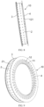
- FIG. 1 is a schematic diagram of an electric vehicle 300 according to some embodiments.
- the electric vehicle 300 may be a pure electric vehicle, a hybrid vehicle, or a range-extended vehicle, etc.
- the electric vehicle 300 is provided with a motor 200, which is used to drive the vehicle to move or drive other components to work.
- the motor 200 may be provided with the electrical energy required for working through the battery provided in the electric vehicle 300.
- the mounting position of the motor 200 may be determined according to the actual needs, and FIG. 1 is only for illustration.
- the motor 200 includes a housing 60, a rotor 40, and a stator assembly 100.
- the rotor 40 is rotatably mounted to the housing 60, and the stator assembly 100 is provided in the housing 60 and coaxially provided around the rotor 40.
- the housing 60 may be cylindrical or other shapes.
- the rotor 40 may be rotatably supported in the housing 60 by means of a bearing 50, and an end of the rotor 40 may extend out of the housing 60 to be connected with a driven mechanism such as an axle.
- the stator assembly 100 is disposed in the housing, and its outer diameter may be adapted to an inner diameter of the housing 60.
- the rotor 40 may sequentially include a first axial section 41, a second axial section 42, and a third axial section 43 in the axial direction.
- the second axial section 42 is connected between the first axial section 41 and the third axial section 43, and bearings 50 are mounted at the first axial section 41 and the third axial section 43 to support the rotor 40 at two ends of the housing 60 in the axial direction.
- the diameter of the second axial section 42 is larger than that of the first axial section 41 and the third axial section 43 to form an air gap with a bore of the stator assembly 100.
- the air gap is provided to allow the rotor 40 to rotate flexibly in the bore of the stator assembly 100 and to meet the performance requirements of the motor 200.
- the stator assembly 100 includes a stator core 20, a winding 30, and a spray ring 10.
- the winding 30 is provided in the stator core 20, and the winding 30 includes an end winding section 302 located at an end of the stator core 20 in the axial direction.
- a gap is formed between the end winding section 302 and the stator core 20, and the end winding section 302 is the member to be cooled.
- At least part of the spray ring 10 is located in the gap between the stator core 20 and the end winding section 302 in the axial direction.
- the spray ring 10 is used to spray the cooling liquid onto the end winding section 302 for cooling.
- the stator core 20 is annular and may be made of a magnetically conductive material such as electrotechnical pure iron.
- a plurality of second teeth 201 are provided arranged at intervals on the radial inner wall of the stator core 20 in the circumferential direction.
- the plurality of second teeth 201 may be evenly distributed in the axial direction, and the second teeth 201 may be rectangular or trapezoidal.
- the winding 30 includes a winding main section 301 and an end winding section 302.
- the winding main section 301 is located within the stator core 20.
- the end winding section 302 protrudes from the end of the stator core 20 in the axial direction of the stator assembly 100.
- the winding 30 may have end winding sections 302 at only one end of the winding main section 301, or may have end winding sections 302 at both ends of the winding main section 301.
- the wires used to form the winding 30 may be U-shaped or I-shaped. The wires are inserted one by one into the grooves formed by two adjacent second teeth 201 of the stator core 20, and are bent and welded at the ends to form the end winding section 302.
- the spray ring 10 is used to spray the cooling liquid onto the end winding section 302 for cooling.
- the cooling liquid may be cooling oil or other liquid cooling media. Since the winding 30 will generate a large amount of heat during a continuous operation of the motor 200, by providing the spray ring 10, a liquid injection hole 614 may be provided on the housing 60 to introduce the cooling liquid from outside into an interior of the housing 60, and the cooling liquid is sprayed onto the end winding sections 302 through the spray ring 10 for cooling.
- the spray ring 10 may be provided on one side of the stator core 20 or on both sides.
- the spray ring 10 includes an annular disc 1 and an annular cylinder 2 coaxially arranged with the annular disc 1.
- the annular cylinder 2 has an end connected to a first end of the annular disc 1 in an axial direction of the spray ring 10, and a connection between the annular cylinder 2 and the annular disc 1 occurs at an outer end of the annular disc 1 in a radial direction of the spray ring 10.
- a region for accommodating a member to be cooled is formed between the annular cylinder 2 and the first end of the annular disc 1.
- a side wall of the annular disc 1 has a first hole 123 for spraying of cooling liquid towards the member to be cooled in a first direction.
- a side wall of the annular cylinder 2 has a second hole 21 for spraying of cooling liquid towards the member to be cooled in a second direction. The first direction is different from the second direction.
- the annular disc 1 may be a circular ring structure. In a state where the spray ring 10 is mounted into the stator assembly 100, the annular disc 1 is embedded in a gap between an end winding section 302 and a stator core 20, facilitating cooling at a side of the end winding section 302 close to the stator core 20. A thickness of the annular disc 1 may be consistent with an axial dimension of the gap. An axial positioning of the spray ring 10 may be realized using the gap, and a mounting positioning of the spray ring 10 may be realized without providing a connection member.
- the annular cylinder 2 may be a cylindrical thin-walled structure.
- the annular cylinder 2 has the end connected to the first end of the annular disc 1 in the axial direction of the spray ring 10, and the connection between the annular cylinder 2 and the annular disc 1 occurs at the outer end of the annular disc 1 in the radial direction of the spray ring 10.
- the annular cylinder 2 and the annular disc 1 may be fixedly connected to each other or integrally formed.
- a radial dimension of the annular cylinder 2 may remain unchanged in the axial direction, or may also gradually increase or decrease in an equal diameter structure.
- an annular disc 1 is provided at only one end of the annular cylinder 2 in the axial direction.
- an annular disc 1 is provided at both ends of the annular cylinder 2 in the axial direction to obtain a better cooling effect.
- the region for accommodating the member to be cooled is formed between the annular cylinder 2 and the first end of the annular disc 1.
- the member to be cooled is the end winding section 302.
- a gap is formed between an outer wall of the end winding section 302 and an inner wall of the annular cylinder 2.
- the cooling liquid may still maintain a certain speed when it is sprayed onto the member to be cooled through the second hole 21, and thus achieving a better cooling effect.
- a side wall of the annular disc 1 has one or more first holes 123 for spraying the cooling liquid towards the member to be cooled in a first direction.
- a side wall of the annular cylinder 2 has one or more second holes for spraying the cooling liquid towards the member to be cooled in a second direction.
- the first direction is different from the second direction.
- the first hole 123 and the second hole 21 may be any shape such as a round hole, a polygonal hole, or the like.
- the spray ring 10 of this embodiment includes the annular disc 1 and the annular cylinder 2.
- the cooling liquid can be sprayed from different directions towards the member to be cooled at the same time through the first hole 123 on the annular disc 1 and the second hole 21 on the annular cylinder 2, so that the member to be cooled has a larger area in contact with the cooling liquid.
- the member to be cooled can be cooled more quickly and evenly. More heat can be taken away, and a cooling effect can be improved.
- the annular disc 1 is located at a radial inner side of the annular cylinder 2, which allows the annular disc 1 to be located on a side of the member to be cooled in the axial direction after mounting.
- the annular disc 1 has a first hole 123, which provides a structural basis for cooling from a side end of the member to be cooled in the axial direction.
- an inner wall of the annular disc 1 has a plurality of grooves 11 arranged at intervals in a circumferential direction.
- the grooves 11 runs through in a thickness direction of the annular disc 1 to form a first tooth 12 between each two adjacent grooves 11.
- the first tooth 12 has a first cavity 121 for storing cooling liquid.
- the first cavity 121 has an opening located on an outer wall of the annular disc 1, and a first wall 122 of at least part of the first tooth 12 close to the annular cylinder 2 has the first hole 123.
- the plurality of first teeth 12 at the radial inner end of the annular disc 1 may be evenly distributed in the circumferential direction.
- the first teeth 12 may be rectangular or trapezoidal.
- the bottom of the groove 11 may be located at an inner side of the inner wall of the annular cylinder 2 to ensure a structural strength of the annular disc 1, allowing the spray ring 10 to be structurally stable.
- the first cavity 121 in the first tooth 12 may be used to store the cooling liquid.
- the first tooth 12 may have a thin-walled structure. The shape of the first cavity 121 matches with the first tooth 12.
- the opening of the first cavity 121 is located at an outer wall of the annular disc 1, and the cooling liquid of the outer side of the annular cylinder 2 may flow into each of the first cavities 121 through the opening, allowing the cooling liquid in the first cavities 121 may be sprayed to a side of the member to be cooled in the axial direction through the first holes 123.
- the first holes 123 may be disposed on the first wall 122 of part of the first teeth 12, or alternatively, the first holes 123 may be disposed on the first wall 122 of all the first teeth 12.
- the plurality of first teeth 12 may have a one-to-one correspondence with the plurality of second teeth 201 on the stator core in the circumferential direction. Therefore, one of the plurality of first teeth 12 and one of the plurality of second teeth 201 that are located at a same circumferential position are wound correspondingly.
- the spray ring 10 may be made of an insulating material to isolate the end winding section 302 and the stator core 20, to increase the insulation between the end winding section 302 and the stator core 20, and to prevent damage to the motor 200 due to insulation problems.
- the cooling liquid can be sprayed from different circumferential positions on one side of the member to be cooled in the axial direction, and a more uniform cooling of the member to be cooled can be achieved.
- the first cavity 121 in each of the first teeth 12 is arranged, which is equivalent to forming a plurality of cooling flow channels, allowing the cooling liquid to be distributed to flow to different positions in the circumferential direction. No additional flow channels are required, and the structure is compact.
- the first direction is parallel to or at an acute angle to the axial direction of the spray ring 10.
- the second direction is parallel to or at an acute angle to the radial direction of the spray ring 10.
- the first direction is parallel to the axial direction.
- the center line of the first hole 123 may be arranged in the axial direction, and the cooling liquid can be sprayed towards the member to be cooled in the axial direction.
- the first direction is at an acute angle to the axial direction.
- the center line of the first hole 123 is at an acute angle to the axial direction, and the cooling liquid can be sprayed towards the member to be cooled in any angle at an acute angle to the axial direction.
- the second direction is parallel to the radial direction.
- the center line of the second hole 21 may be arranged in the radial direction, and the cooling liquid can be sprayed towards the member to be cooled in the radial direction.
- the second direction is at an acute angle to the radial direction.
- the center line of the second hole 21 is at an acute angle to the radial direction, and the cooling liquid can be sprayed towards the member to be cooled in any angle at an acute angle to the radial direction.
- a center line of the first hole 123 is provided in the axial direction, and a center line of the second hole 21 is provided in the radial direction.
- This embodiment can select the suitable first direction and second direction according to actual needs so as to cool the member to be cooled from different directions at the same time.
- the cooling may be carried out by spraying the cooling liquid from the axial direction and the radial direction at the same time, so that the member to be cooled has a larger area in contact with the cooling liquid.
- the member to be cooled is cooled more quickly and evenly, and the cooling effect can be improved.
- the spray ring 10 further includes a first mounting portion 3.
- a radial inner end of the first mounting portion 3 is connected to a second end of the annular cylinder 2 in an axial direction and extends in an entire circumferential direction.
- a radial outer end of the first mounting portion 3 is configured to be connected to a housing 60.
- the first mounting portion 3 is folded outward in the radial direction relative to the second end of the annular cylinder 2 to be connected to the housing 60.
- the radial outer end of the first mounting portion 3 may abut against the inner wall of the housing 60 to achieve connection or may also be connected to the housing 60 by bonding or fastener connection.
- a cavity for collecting the cooling liquid may be formed on the radial outer side of the annular cylinder 2.
- the first mounting portion 3 closes between the inner wall of the housing 60 and the second end of the annular cylinder 2.
- the radial outer end of the first mounting portion 3 is provided with a sealing member 5.
- the sealing member 5 is configured to form a sealing connection between the radial outer end of the first mounting portion 3 and the housing 60.
- the sealing member 5 may be a rubber sealing member, and may be an annular sealing member provided around the radial outer end of the first mounting portion 3.
- the cross-section of the sealing member 5 may be circular or rectangular.
- the radial outer region of the annular cylinder 2 can form a cavity for collecting the cooling liquid by a blocking of the first mounting portion 3 and the sealing effect of the sealing member 5.
- the cooling liquid can be sprayed out continuously and stably through the first hole 123 and the second hole 21, better cooling effect can be achieved, and the input amount of the cooling liquid can be further saved.
- the first mounting portion 3 includes a plate-shaped portion 31 and a protrusion portion 32.
- a radial inner end of the plate-shaped portion 31 is connected to the second end of the annular cylinder 2 in the axial direction.
- a protrusion portion 32 is connected to a radial outer end of the plate-shaped portion 31 and protrudes in the axial direction towards at least one side relative to the plate-shaped portion 31.
- a radial outer side of the protrusion portion 32 has an accommodation groove 321 for placing the sealing member 5.
- the plate-shaped portion 31 may be provided perpendicular to the annular cylinder 2, or at an acute or obtuse angle to the annular cylinder 2, and the plate-shaped portion 31 may extend in the entire circumferential direction.
- the protrusion portion 32 is provided at the radial outer end of the plate-shaped portion 31 and may, for example, protrude towards the outer side, the inner side, or both sides relative to the plate-shaped portion 31 in the axial direction.
- the first mounting portion 3 of this embodiment can design the main portion as a thinner plate-shaped structure to reduce the weight of the spray ring 10, and provide a protrusion portion 32 with an increased cross-sectional area at the radial outer end of the plate-shaped portion 31 to allow the radial outer end of the first mounting portion 3 to have a sufficient area to mount the sealing member 5.
- the spray ring 10 further includes a second mounting portion 4.
- a radial inner end of the second mounting portion 4 is connected to the radial outer end of the annular disc 1 and extends in the entire circumferential direction.
- the second mounting portion 4 is located at a side of the annular disc 1 facing away from the annular cylinder 2 in the axial direction.
- a radial outer end of the second mounting portion 4 is configured to be connected to the housing 60.
- the second mounting portion 4 may be of a plate-shaped structure and may be connected by abutting against the inner wall of the housing 60, or may also be connected by bonding or fasteners.
- the second mounting portion 4 may be located at a side of the first cavity 121 away from the annular cylinder 2.
- a second mounting portion 4 not only can the spray ring 10 be easily mounted in the housing 60, but also a radial outer region of the annular cylinder 2 can form a cavity for collecting the cooling liquid through a blocking of the second mounting portion 4.
- the cooling liquid can be sprayed out continuously and stably through the first hole 123 and the second hole 21, better cooling effect can be achieved, and the input amount of the cooling liquid can be saved.
- the second mounting portion 4 is flush with and forms a flat plane with an outer end surface of the annular disc 1 facing away from the annular cylinder 2 in an axial direction.
- the second mounting portion 4 is flush with an outer end surface of the first teeth 12 facing away from the annular cylinder 2 in the axial direction.
- the arrangement of the second mounting portion 4 can avoid affecting the flow of the cooling liquid into the first cavity 121 without increasing an axial dimension of the spray ring 10.
- the second mounting portion 4 is flush with the outer end surface of the annular disc 1, which makes it easy to allow a plane formed by the second mounting portion 4 and the outer end surface of the annular disc 1 abuts against other members to achieve axial limitation and allows the mounting of the spray ring 10 more stable.
- the plane as a whole fits with the end surface of the stator core 20, which not only improves the mounting stability of the spray ring 10, but also reduces the axial dimension of the stator assembly 100.
- the second wall 124 of the first teeth 12 away from the annular cylinder 2 fits with the end surface of the stator core 20.
- the spray ring 10 further includes a first mounting portion 3 and a second mounting portion 4.
- a radial inner end of the first mounting portion 3 is connected to a second end of the annular cylinder 2 in an axial direction and extends in an entire circumferential direction.
- a radial inner end of the second mounting portion 4 is connected to a radial outer end of the annular disc 1 and extends in the entire circumferential direction.
- the second mounting portion 4 is located on a side of the annular disc 1 facing away from the annular cylinder 2 in the axial direction. Radial outer ends of the first mounting portion 3 and the second mounting portion 4 is configured to be connected to the housing 60.
- the first mounting portion 3, the annular cylinder 2, and the second mounting portion 4 define a second cavity 6 in communication with all of the first cavities 121.
- the second cavity 6 forms a cavity for collecting the cooling liquid.
- the second cavity 6 is an annular cavity and may be in communication with all the first cavities 121 distributed in the circumferential direction.
- the second cavity 6 is defined by the first mounting portion 3, the annular cylinder 2, the second mounting portion 4, and the inner wall of the housing 60.
- a liquid injection hole 614 is provided at a position corresponding to the first cavity 121 on the side wall of the housing 60.
- the cooling liquid introduced through the liquid injection hole 614 enters the second cavity 6 to spray the cooling liquid towards the member to be cooled in a second direction through the second hole 21.
- the cooling liquid in the second cavity 6 flows into each of the first cavities 121 in the circumferential direction to spray the cooling liquid towards the member to be cooled in a first direction through the first holes 123.
- This embodiment forms a second cavity 6 by arranging the first mounting portion 3 and the second mounting portion 4.
- the cooling liquid can be collected in the radial outer region of the annular cylinder 2 and be supplied to each of the first cavities 121 by flowing in the circumferential direction.
- the cooling liquid can be sprayed out through the first hole 123 and the second hole 21 evenly and stably, and the cooling effect of the member to be cooled can be improved.
- the radial outer end of the second mounting portion 4 is higher than the radial outer end of the first mounting portion 3.
- an outer diameter of the second mounting portion 4 is larger than an outer diameter of the first mounting portion 3.
- the radial outer end of the second mounting portion 4 is higher than the radial outer end of the first mounting portion 3.
- an axial limitation of the spray ring 10 in the housing 60 can be achieved by a higher portion of the second mounting portion 4 abutting against a step structure of the inner wall of the housing 60.
- a first wall 122 of the first tooth 12 has a plurality of first holes 123 arranged at intervals in the radial direction.
- the plurality of first holes 123 may be arranged at intervals evenly in the radial direction.
- the first hole 123 may be provided on each of the first teeth 12, and a plurality of first holes 123 may be provided on each of the first teeth 12 arranged at intervals in the radial direction.
- the first holes 123 may be provided only on part of the first teeth 12, or the first holes 123 may be arranged differently on different first teeth 12.
- a spraying range of the cooling liquid in the radial direction can be increased on the basis of the cooling liquid being sprayed out through the plurality of first teeth 12 in the circumferential direction.
- a contact area between the cooling liquid and the member to be cooled can be increased and uniformity of the cooling liquid sprayed onto the member to be cooled can be improved. This can take away more heat and optimize the cooling effect.
- a side wall of the annular cylinder 2 has a plurality of second holes 21.
- the plurality of second holes 21 is arranged in at least one row in the axial direction, and each row of the at least row includes multiple ones of the plurality of second holes 21 arranged at intervals in the circumferential direction of the spray ring 10.
- two adjacent rows of second holes 21 may be opposite or staggered in the circumferential direction.
- each row of second holes 21 includes a plurality of second holes 21 arranged at intervals in the circumferential direction, which can spray the cooling liquid to the member to be cooled from different angles in the circumferential direction; or when multiple rows of second holes 21 are provided in the axial direction, a spraying range of the cooling liquid in the axial direction can be increased to increase a contact area between the cooling liquid and the member to be cooled and to improve the uniformity of the cooling liquid sprayed onto the member to be cooled, which can take away more heat and optimize the cooling effect.
- an inner wall of the annular disc 1 has a plurality of grooves 11 arranged at intervals in a circumferential direction.
- the plurality of grooves 11 runs through in a thickness direction of the annular disc 1 to form a first tooth 12 between each two adjacent grooves 11.
- the stator core 20 is annular.
- a plurality of second teeth 201 is arranged at a radial inner wall of the stator core 20 and is arranged at intervals in a circumferential direction.
- the plurality of second teeth 201 has a one-to-one correspondence with a plurality of first teeth 12 in the circumferential direction.
- One of the plurality of first teeth 12 and one of the plurality of second teeth 201 that are located at a same circumferential position are wound correspondingly.
- the plurality of second teeth 201 have a one-to-one correspondence with a plurality of first teeth 12 in the circumferential direction, that is, each pair of the first tooth 12 and the second tooth 201 are located at a same circumferential position.
- the shape and dimension of the first teeth 12 and the second teeth 201 may be the same to facilitate winding while maximizing the volume of the first cavity 121 to accommodate more cooling liquid, allowing the cooling liquid to be sprayed continuously and stably through the first hole 123.
- a first end of the annular disc 1 in the axial direction abuts against the end winding section 302, and a second end of the annular disc 1 in the axial direction abuts against an end surface of the stator core 20.
- the first walls 122 of all first teeth 12 abut against the end winding section 302, and the second walls 124 of all first teeth 12 abut against the end surface of the stator core 20. Since the first hole 123 is provided on the first wall 122, the cooling liquid may be sprayed from the first hole 123 to directly cool the end winding section 302. Therefore, the first teeth 12 not only collect the cooling liquid to be sprayed through the first hole 123 to cool the end winding section 302, but also play a positioning role in the mounting of the spray ring 10.
- the structure of this embodiment enables the two ends of the annular disc 1 in the axial direction to abut against the end surfaces of the end winding section 302 and the stator core 20 respectively.
- the annular disc 1 can be axially limited through the gap space between the end winding section 302 and the stator core 20, which can simplify the fixed mounting structure of the spray ring 10.
- a motor 200 includes a housing 60, a rotor 40, and the stator assembly 100.
- the rotor 40 is rotatably mounted to the housing 60, and the stator assembly 100 is provided in the housing 60 and coaxially provided around the rotor 40.
- the cooling liquid can be sprayed on the end winding section 302 in the stator assembly 100 through the spray ring 10 in different first and second directions to improve the cooling effect of the end winding section 302.
- the motor 200 can be kept working in a suitable temperature range, and the working performance, reliability, and life of the motor 200 can be improved.
- the spray ring 10 further includes a first mounting portion 3 and a second mounting portion 4.
- the first mounting portion 3 has a radial inner end connected to a second end of the annular cylinder 2 in an axial direction and extends in an entire circumferential direction.
- the second mounting portion 4 has a radial inner end connected to a radial outer end of the annular disc 1 and extends in the entire circumferential direction.
- the second mounting portion 4 is located on a side of the annular disc 1 facing away from the annular cylinder 2 in the axial direction.
- the housing 60 includes an accommodation shell 61 and an end cover 62.
- the accommodation shell 61 sequentially has a third hole 611 and a fourth hole 612 in the axial direction, and one end of the third hole 611 facing away from the fourth hole 612 forms an opening of the accommodation shell 61.
- a diameter of the third hole 611 is greater than that of the fourth hole 612 to form a step 613 at a connection.
- the end cover 62 is configured to close the opening.
- the end winding section 302 is formed at both ends of the stator core 20 in the axial direction.
- the spray ring 10 provided between the end winding section 302 away from the end cover 62 and the stator core 20 is the first spray ring 10A
- the spray ring 10 provided between the end winding section 302 close to the end cover 62 and the stator core 20 is a second spray ring 10B.
- the first mounting portion 3 of the first spray ring 10 fits with and is connected to the inner wall of the fourth hole 612.
- the second mounting portion 4 of the first spray ring 10 abuts against the step 613.
- the first mounting portion 3 of the second spray ring 10 fits with and is connected to the inner wall of the third hole 611 and abuts against an end surface of the end cover 62.
- the second mounting portion 4 of the second spray ring 10 abuts against the inner wall of the third hole 611.
- the housing 60 may be in the form of a cylindrical cartridge structure including an accommodation shell 61 and an end cover 62.
- the accommodation shell 61 and the end cover 62 are respectively provided with holes for mounting the bearings 50 at opposite positions in the axial direction.
- the end winding sections 302 are formed at both ends of the stator core 20 in the axial direction, and the first spray ring 10A and the second spray ring 10B are respectively used to spray the cooling liquid on the two end winding sections 302 for cooling.
- the structures of the first spray ring 10A and the second spray ring 10B may be exactly the same or may have differences.
- the spray ring 10 may also be provided on only one of the end winding sections 302.
- the first mounting portion 3 of the first spray ring 10 is cooperatively connected with the inner wall of the fourth hole 612.
- the first mounting portion 3 may directly abut against the inner wall of the fourth hole 612, or the first mounting portion 3 may abut against the inner wall of the fourth hole 612 through the sealing member 5.
- the second mounting portion 4 of the first spray ring 10A abuts against the step 613 to axially limit the first spray ring 10A.
- the outer diameter of the second mounting portion 4 of the first spray ring 10 may be consistent with the diameter of the third hole 611, or may be smaller than the diameter of the third hole 611.
- the first mounting portion 3 of the second spray ring 10B is cooperatively connected with the inner wall of the third hole 611 and abuts against the end surface of the end cover 62.
- the first mounting portion 3 may directly abut against the inner wall of the third hole 611, or the first mounting portion 3 may abut against the inner wall of the third hole 611 through the sealing member 5.
- the first mounting portion 3 abuts against the end surface of the end cover 62 to axially limit the second spray ring 10B.
- the second mounting portion 4 of the spray ring 10 may abut against the inner wall of the third hole 611, for example, it may directly abut against the inner wall of the third hole 611.
- end winding sections 302 are respectively provided on both sides of the stator core 20.
- the two end winding sections 302 can be cooled respectively to optimize the cooling effect of the motor 200.
- steps 613 on the inner wall of the accommodation shell 61 and designing the housing 60 into a split structure it is possible to not only achieve the smooth mounting of the two spray rings 10, but also axially limit the two spray rings 10.
- the spray ring 10 further includes a first mounting portion 3.
- a radial inner end of the first mounting portion 3 is connected to the second end of the annular cylinder 2 in the axial direction and extends in the entire circumferential direction, and the first mounting portion 3 is sealingly connected to the housing 60.
- a radial outer end of the first mounting portion 3 may be provided with an accommodation groove 321, and a sealing member 5 is provided in the accommodation groove 321 to achieve a sealing connection between the first mounting portion 3 and the housing 60.
- the first mounting portion 3 by allowing the first mounting portion 3 to be sealingly connected to the housing 60, the first mounting portion 3, the second mounting portion, the annular cylinder 2, and the housing 60 can define a second cavity 6, which facilitates the collection of the cooling liquid and prevents the cooling liquid from flowing out through the gap between the first mounting portion 3 and the housing 60.
- the end winding sections 302 are formed at both ends of the stator core 20 in the axial direction.
- the first spray ring 10A and the second spray ring 10B are respectively used to spray the cooling liquid for cooling the two end winding sections 302, which are respectively located at both sides of a second axial section 42 of the rotor 40.
- Gaps are formed between the respective annular cylinder 2 of the first spray ring 10A and the second spray ring 10B and the end winding 302, and a gap is formed between the end surface of the stator core 20 and the end surface of the end winding section 302.
- the annular disc 1 of the spray ring 10 is embedded in the gap to achieve the axial positioning of the spray ring 10.
- the dimension of the spray ring 10 in the axial direction may substantially cover the end winding section 302.
- the annular cylinder 2 may have a plurality row of second holes 21.
- Each row of the plurality rows of second holes 21 may include a plurality of second holes 21 arranged at intervals in the circumferential direction.
- the radial outer end of the second mounting portion 4 may be flush with the stator core 20.
- a plurality of first teeth 12 are provided arranged at intervals on a radial inner end of the annular disc 1 in the circumferential direction.
- the first teeth 12 has a first cavity 121 inside, and the first wall 122 of the first teeth 12 close to the annular cylinder 2 may have a first hole 123.
- the first wall 122 may have a plurality of first holes 123 arranged at intervals in the radial direction.
- Each of the first cavities 121 is in communication with the second cavity 6.
- the second cavity 6 is defined by the first mounting portion 3, the second mounting portion 4, the annular cylinder 2, and the inner wall of the housing 60.
- the first spray ring 10A and the second spray ring 10B have separate liquid injection holes 614 on the housing 60.
Landscapes
- Engineering & Computer Science (AREA)
- Power Engineering (AREA)
- Motor Or Generator Cooling System (AREA)
Applications Claiming Priority (2)
| Application Number | Priority Date | Filing Date | Title |
|---|---|---|---|
| CN202220837742.XU CN217769761U (zh) | 2022-04-12 | 2022-04-12 | 喷环、定子组件、电机和电动车辆 |
| PCT/CN2023/082035 WO2023197819A1 (zh) | 2022-04-12 | 2023-03-17 | 喷环、定子组件、电机和电动车辆 |
Publications (2)
| Publication Number | Publication Date |
|---|---|
| EP4407846A1 true EP4407846A1 (de) | 2024-07-31 |
| EP4407846A4 EP4407846A4 (de) | 2025-07-09 |
Family
ID=83883051
Family Applications (1)
| Application Number | Title | Priority Date | Filing Date |
|---|---|---|---|
| EP23787467.2A Pending EP4407846A4 (de) | 2022-04-12 | 2023-03-17 | Sprühring, statoranordnung, motor und elektrofahrzeug |
Country Status (3)
| Country | Link |
|---|---|
| EP (1) | EP4407846A4 (de) |
| CN (1) | CN217769761U (de) |
| WO (1) | WO2023197819A1 (de) |
Families Citing this family (5)
| Publication number | Priority date | Publication date | Assignee | Title |
|---|---|---|---|---|
| CN217769761U (zh) * | 2022-04-12 | 2022-11-08 | 宁德时代(上海)智能科技有限公司 | 喷环、定子组件、电机和电动车辆 |
| US12388326B2 (en) * | 2022-11-30 | 2025-08-12 | Dana Automotive Systems Group, Llc | Electric machine with a cooling assembly |
| DE102023100964A1 (de) * | 2023-01-17 | 2024-07-18 | Schaeffler Technologies AG & Co. KG | Stator, Verfahren zur Herstellung eines Stators und Kit-of-parts |
| DE102023201150A1 (de) * | 2023-02-13 | 2024-08-14 | Zf Friedrichshafen Ag | Fluidleitelement für eine elektrische Maschine, elektrische Maschine und Fahrzeug |
| CN118826383A (zh) * | 2023-04-21 | 2024-10-22 | 法雷奥新能源汽车德国有限责任公司 | 电机冷却布置、喷油环、电机和车辆 |
Family Cites Families (10)
| Publication number | Priority date | Publication date | Assignee | Title |
|---|---|---|---|---|
| JP5088577B2 (ja) * | 2008-08-22 | 2012-12-05 | アイシン・エィ・ダブリュ株式会社 | 回転電機 |
| JP5920108B2 (ja) * | 2012-08-23 | 2016-05-18 | トヨタ自動車株式会社 | 回転電機装置 |
| CN109936241A (zh) * | 2019-03-27 | 2019-06-25 | 上海蔚来汽车有限公司 | 电机 |
| CN110808645B (zh) * | 2019-11-04 | 2021-11-12 | 合肥巨一动力系统有限公司 | 一种应用于油冷扁线电机定子的冷却结构 |
| CN111342586B (zh) * | 2020-02-28 | 2022-04-22 | 华为数字能源技术有限公司 | 电机、动力总成和汽车 |
| CN213243760U (zh) * | 2020-08-03 | 2021-05-18 | 安徽威灵汽车部件有限公司 | 油冷电机和车辆 |
| JP7364544B2 (ja) * | 2020-09-10 | 2023-10-18 | 大豊工業株式会社 | モータの冷却部材及びモータの冷却構造 |
| CN112615445B (zh) * | 2020-11-25 | 2022-05-13 | 华为数字能源技术有限公司 | 电机、动力总成和设备 |
| CN113783323B (zh) * | 2021-09-15 | 2022-11-15 | 臻驱科技(上海)有限公司 | 一种电机定子冷却结构 |
| CN217769761U (zh) * | 2022-04-12 | 2022-11-08 | 宁德时代(上海)智能科技有限公司 | 喷环、定子组件、电机和电动车辆 |
-
2022
- 2022-04-12 CN CN202220837742.XU patent/CN217769761U/zh active Active
-
2023
- 2023-03-17 WO PCT/CN2023/082035 patent/WO2023197819A1/zh not_active Ceased
- 2023-03-17 EP EP23787467.2A patent/EP4407846A4/de active Pending
Also Published As
| Publication number | Publication date |
|---|---|
| EP4407846A4 (de) | 2025-07-09 |
| CN217769761U (zh) | 2022-11-08 |
| WO2023197819A1 (zh) | 2023-10-19 |
Similar Documents
| Publication | Publication Date | Title |
|---|---|---|
| EP4407846A1 (de) | Sprühring, statoranordnung, motor und elektrofahrzeug | |
| CN104079109B (zh) | 轴方向磁束电动机 | |
| US8072114B2 (en) | Electric motor with bar winding and connection plates | |
| CN116325307A (zh) | 蓄能器电芯 | |
| US11936056B2 (en) | Battery module, battery pack, and vehicle | |
| CN113644784A (zh) | 油冷驱动电机及汽车 | |
| US11626636B2 (en) | Immersion cooling battery array designs for electrified vehicle battery packs | |
| KR102890100B1 (ko) | 전지, 장치, 전지의 제조 방법 및 설비 | |
| CN220210045U (zh) | 电机、电驱动装置、电驱动系统及电动设备 | |
| EP4668442A1 (de) | Batteriekastenkörper zum stapeln in mehreren schichten und system | |
| WO2024146212A1 (zh) | 一种轴向磁通电机、电动设备和交通工具 | |
| WO2024040851A1 (zh) | 一种轴向磁通电机、电动设备和交通工具 | |
| KR20240043949A (ko) | Afpm 모터 고정자 및 그 제조 방법 | |
| CN116937839A (zh) | 定子组件、轴向磁通电机和车辆 | |
| WO2024146213A1 (zh) | 一种轴向磁通电机、电动设备和交通工具 | |
| CN222234504U (zh) | 轴向磁通电机的定子及轴向磁通电机 | |
| CN222619848U (zh) | 一种浸没式液冷电池包 | |
| CN221597517U (zh) | 一种电机定子冷却结构及电机 | |
| CN218299934U (zh) | 电池模组及电池包 | |
| EP4507174A1 (de) | Sprühring, motor und fahrzeug | |
| US11876419B2 (en) | Electric motor for aircraft propulsion | |
| WO2024217036A1 (zh) | 电机、电驱动装置、电驱动系统及电动设备 | |
| CN213367538U (zh) | 具有冷却装置的永磁盘式取力发电机 | |
| KR20210119663A (ko) | 토로이달 모터, 그 제조 방법 및 이를 포함하는 공기압축기 | |
| CN113162281A (zh) | 一种具有冷却结构的外转子电机 |
Legal Events
| Date | Code | Title | Description |
|---|---|---|---|
| STAA | Information on the status of an ep patent application or granted ep patent |
Free format text: STATUS: THE INTERNATIONAL PUBLICATION HAS BEEN MADE |
|
| PUAI | Public reference made under article 153(3) epc to a published international application that has entered the european phase |
Free format text: ORIGINAL CODE: 0009012 |
|
| STAA | Information on the status of an ep patent application or granted ep patent |
Free format text: STATUS: REQUEST FOR EXAMINATION WAS MADE |
|
| 17P | Request for examination filed |
Effective date: 20240425 |
|
| AK | Designated contracting states |
Kind code of ref document: A1 Designated state(s): AL AT BE BG CH CY CZ DE DK EE ES FI FR GB GR HR HU IE IS IT LI LT LU LV MC ME MK MT NL NO PL PT RO RS SE SI SK SM TR |
|
| REG | Reference to a national code |
Ref country code: DE Ref legal event code: R079 Free format text: PREVIOUS MAIN CLASS: H02K0009000000 Ipc: H02K0009190000 |
|
| A4 | Supplementary search report drawn up and despatched |
Effective date: 20250610 |
|
| RIC1 | Information provided on ipc code assigned before grant |
Ipc: H02K 3/48 20060101ALI20250603BHEP Ipc: H02K 5/20 20060101ALI20250603BHEP Ipc: H02K 3/24 20060101ALI20250603BHEP Ipc: H02K 9/19 20060101AFI20250603BHEP |
|
| DAV | Request for validation of the european patent (deleted) | ||
| DAX | Request for extension of the european patent (deleted) |