EP4407799A1 - Compact dual band antenna - Google Patents
Compact dual band antenna Download PDFInfo
- Publication number
- EP4407799A1 EP4407799A1 EP24151591.5A EP24151591A EP4407799A1 EP 4407799 A1 EP4407799 A1 EP 4407799A1 EP 24151591 A EP24151591 A EP 24151591A EP 4407799 A1 EP4407799 A1 EP 4407799A1
- Authority
- EP
- European Patent Office
- Prior art keywords
- antenna element
- antenna
- less
- millimeters
- dual band
- Prior art date
- Legal status (The legal status is an assumption and is not a legal conclusion. Google has not performed a legal analysis and makes no representation as to the accuracy of the status listed.)
- Granted
Links
Images




Classifications
-
- H—ELECTRICITY
- H01—ELECTRIC ELEMENTS
- H01Q—ANTENNAS, i.e. RADIO AERIALS
- H01Q9/00—Electrically-short antennas having dimensions not more than twice the operating wavelength and consisting of conductive active radiating elements
- H01Q9/04—Resonant antennas
- H01Q9/30—Resonant antennas with feed to end of elongated active element, e.g. unipole
- H01Q9/42—Resonant antennas with feed to end of elongated active element, e.g. unipole with folded element, the folded parts being spaced apart a small fraction of the operating wavelength
-
- H—ELECTRICITY
- H01—ELECTRIC ELEMENTS
- H01Q—ANTENNAS, i.e. RADIO AERIALS
- H01Q5/00—Arrangements for simultaneous operation of antennas on two or more different wavebands, e.g. dual-band or multi-band arrangements
- H01Q5/30—Arrangements for providing operation on different wavebands
- H01Q5/307—Individual or coupled radiating elements, each element being fed in an unspecified way
-
- H—ELECTRICITY
- H01—ELECTRIC ELEMENTS
- H01Q—ANTENNAS, i.e. RADIO AERIALS
- H01Q1/00—Details of, or arrangements associated with, antennas
- H01Q1/12—Supports; Mounting means
- H01Q1/22—Supports; Mounting means by structural association with other equipment or articles
- H01Q1/2291—Supports; Mounting means by structural association with other equipment or articles used in Bluetooth® or Wi-Fi® devices of Wireless Local Area Networks [WLAN]
-
- H—ELECTRICITY
- H01—ELECTRIC ELEMENTS
- H01Q—ANTENNAS, i.e. RADIO AERIALS
- H01Q1/00—Details of, or arrangements associated with, antennas
- H01Q1/48—Earthing means; Earth screens; Counterpoises
-
- H—ELECTRICITY
- H01—ELECTRIC ELEMENTS
- H01Q—ANTENNAS, i.e. RADIO AERIALS
- H01Q5/00—Arrangements for simultaneous operation of antennas on two or more different wavebands, e.g. dual-band or multi-band arrangements
- H01Q5/30—Arrangements for providing operation on different wavebands
- H01Q5/378—Combination of fed elements with parasitic elements
-
- H—ELECTRICITY
- H01—ELECTRIC ELEMENTS
- H01Q—ANTENNAS, i.e. RADIO AERIALS
- H01Q9/00—Electrically-short antennas having dimensions not more than twice the operating wavelength and consisting of conductive active radiating elements
- H01Q9/04—Resonant antennas
- H01Q9/0407—Substantially flat resonant element parallel to ground plane, e.g. patch antenna
Definitions
- the present disclosure pertains to antennas that may be used in a variety of wireless applications and more particularly pertains to dual band antennas having a small physical footprint.
- a variety of electronic devices utilize antennas for wirelessly transmitting and/or receiving information.
- What would be desirable is a dual band antenna that can be easily and inexpensively incorporated into a variety of different electronic devices to support communication over each of two different frequency bands.
- This disclosure pertains to antennas that may be used in a variety of wireless applications and more particularly pertains to dual band antennas having a small physical footprint.
- An example may be found in a dual band antenna that includes a ground plane formed by a first conductive layer of a Printed Circuit Board (PCB).
- a first antenna element is formed by the first conductive layer of the PCB, where the first antenna element is spaced from and electrically isolated from the ground plane.
- the first antenna element is configured to resonate in a first frequency band.
- a second antenna element is also formed by the first conductive layer of the PCB.
- the second antenna element is electrically connected to the ground plane and electromagnetically coupled to the first antenna element.
- the second antenna element is configured to resonate in a second frequency band.
- the first antenna element and the second antenna element are configured to fit within a rectangular area of less than about 100 square millimeters on the PCB.
- the antenna system includes a first antenna that is configured to resonate in a first frequency band and a second antenna that is configured to resonate in a second frequency band.
- the first antenna includes a base element having a major dimension of less than about 5 millimeters, and a cross element extending at least substantially orthogonally to the base element.
- the cross element is electrically connected with the base element and has a major dimension of less than about 10 millimeters.
- the base element is operatively coupled to a signal trace that is operatively coupled to an antenna driver and/or receiver.
- the example antenna system also includes a second antenna that is spaced from the first antenna and is configured to resonate in a second frequency band. The second antenna is electromagnetically coupled to the first antenna.
- the second antenna includes a first member extending at least substantially parallel with the base element of the first antenna and alongside a first end of the cross element of the first antenna.
- the first member has a major dimension of less than about 10 millimeters and is electrically connected to a ground plane.
- the second antenna further includes a second member that is electrically connected with the first member and extending along the cross element of the first antenna and at least substantially parallel with the major dimension of the cross element of the first antenna.
- the second member has a major dimension of less than about 15 millimeters.
- the second antenna further includes a third member that is electrically connected with the second member and extending at least substantially parallel with the first member of the first antenna and alongside a second end of the cross element opposite the first end.
- the third member has a major dimension that is less than the major dimension of the first member of the second antenna.
- the antenna system includes a first antenna element configured to resonate in a first frequency band centered at about 5.4 GHz and a second antenna element configured to resonate in a second frequency band centered at about 2.4 GHz.
- the first antenna element and the second antenna element may be electromagnetically coupled to one another and may fit within a rectangular area of less than about 100 square millimeters on the PCB.
- the first antenna element has a bandwidth of at least 2 GHz and the second antenna element has a bandwidth of at least 100 MHz, wherein the bandwidth is defined as having less than a -10 dB return loss within the band.
- the first antenna element and the second antenna element, along with a ground plane are patterned from a common conductive layer of the PCB, thereby forming a single conductive layer dual band antenna that has a small footprint and wide upper and lower frequency bands.
- references in the specification to "an embodiment”, “some embodiments”, “other embodiments”, etc., indicate that the embodiment described may include a particular feature, structure, or characteristic, but every embodiment may not necessarily include the particular feature, structure, or characteristic. Moreover, such phrases are not necessarily referring to the same embodiment. Further, when a particular feature, structure, or characteristic is described in connection with an embodiment, it is contemplated that the feature, structure, or characteristic may be applied to other embodiments whether or not explicitly described unless clearly stated to the contrary.
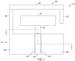
- FIG 1 is a schematic diagram of an illustrative dual band antenna 10 and Figure 2 is a cross-sectional view of the dual band antenna 10, taken along the line 2-2 of Figure 1 .
- the dual band antenna 10 includes a ground plane 12 that, as seen in Figure 2 , is formed by a first conductive layer 14 of a Printed Circuit Board (PCB) 16.
- a first antenna element 18 is also formed by the first conductive layer 14 of the PCB 16, and is laterally spaced from and electrically isolated from the ground plane 12 as shown in Figure 1 .
- the first antenna element 18 may be electrically coupled to a signal 23 that is driven and/or received by an antenna driver and/or receiver component.
- the first antenna element 18 may be configured to resonate in a first frequency band with a bandwidth of at least 2 GHz.
- the first frequency band may be centered at about 5.4 GHz.
- a second antenna element 20 is also formed by the first conductive layer 14 of the PCB 16.
- the second antenna element 20 is electrically connected to the ground plane 12 and is configured to be electrically isolated from but electromagnetically coupled to the first antenna element 18.
- the second antenna element 20 may have a bandwidth of at least 100 MHz and may be considered as being configured to resonate in a second frequency band.
- the second frequency band may be centered at about 2.4 GHz.
- the "bandwidth" of the first frequency band and the "bandwidth" of the second frequency band may be defined as having less than a -10 dB return loss within the band.
- a first frequency band that is centered at about 5.4 GHz may refer to a frequency band that is centered at 5.4 GHz ⁇ 20 percent, or 5.4 GHz ⁇ 10 percent.
- the first frequency band may range from about 5.15 GHz to about 5.85 GHz.
- a second frequency band that is centered at about 2.4 GHz may refer to a frequency band that is centered at 2.4 GHz ⁇ 20 percent, or 2.4 GHz ⁇ 10 percent.
- the first frequency band may be suitable for WiFi communication
- the second frequency band may be suitable for WiFi and/or Bluetooth communication.
- the first antenna element 18 may be considered as being T-shaped, with a first member 22 forming a vertical (in the illustrated orientation) portion of the T and a second member 24 that is orthogonal to the vertical portion (the first member 22).
- the second antenna element 20 may be spaced from and may extend along at least part of at least three sides of the second member 24 of the first antenna element 18.
- the second antenna element 20 includes a third member 26 that extends at least substantially parallel with the first member 22 of the first antenna element 18, a fourth member 28 that is connected with the third member 26 and extends at least substantially parallel with the second member 24 of the first antenna element 18, and a fifth member 30 that is connected with the fourth member 28 and extends at least substantially parallel with the third member 26.
- the ground plane 12 may be considered as being divided into a first ground plane 12a and a second ground plane 12b.
- a conductive element 42 is electrically isolated from the first ground plane 12a and the second ground plane 12b via etched areas 44.
- the conductive layer 42 may be electrically coupled with the first member 22 of the first antenna element 18.
- the illustrative PCB 16 may include a second conductive layer 32 that is patterned on a second side of the PCB 16 opposite that of the first conductive layer 14.
- the second conductive layer 32 may be electrically coupled with the conductive element 42, and hence with the first antenna element 18, by an electrically conductive via 34 that passes through an insulative layer 36 of the PCB 16.
- the insulative layer 36 of the PCB 16 may have a thickness of 1.6 millimeters, and may be formed of, or otherwise include, FR4.
- FR4 is a fiberglass-reinforced epoxy laminate material, and is considered to be flame-retardant.
- FR-4 glass epoxy has a good strength to weight ratio.
- an electrical device 38 may be coupled to the second conductive layer 32.
- the electrical device 38 may be a transmitter and/or a receiver, and may include an electrical contact that is electrically coupled to the second conductive layer 32, and thus electrically connected to the first antenna element 18 via the conductive element 42 and the conductive via 34.
- the electrical device 38 may include an impedance matching circuitry, filtering circuitry (e.g. bandpass filtering) and/or amplification circuitry, for example.
- a portion of the second conductive layer 32, including the conductive element 42 and the conductive via 34, may be considered as having an impedance that matches that of the dual band antenna 10. This may help prevent signal reflections at the interface, thereby improving the effective antenna efficiency.
- the conductive path between the electrical device 38 and a contact point of the dual band antenna 10 may represent a transmission line (e.g. co-planer microstrip line) that has an impedance of about 50 ohms, and the dual band antenna 10 may represent an impedance of about 50 ohms.
- Figure 3 is similar to Figure 1 , but labels a number of dimensions of the dual band antenna 10.
- the first member 22 may be considered as being a base element while the second member 24 may be considered as being a cross element that extends at least substantially orthogonally to the base element.
- the first member 22 may be considered as having a major dimension D1 that is less than about 5 millimeters and a minor dimension D2 that is less than about 2 millimeters.
- the second member 24 may have a major dimension D3 that is less than about 10 millimeters and a minor dimension D4 that is less than about 4 millimeters.
- the third member 26 has a major dimension D5 of less than about 10 millimeters and a minor dimension D6 of less than 1 millimeter.
- the fourth member 28 has a major dimension D7 of less than about 15 millimeters and a minor dimension D8 of less than about 1.5 millimeters.
- the fifth member 30 has a major dimension D9 of less than D5 and a minor dimension D10 of less than 1.5 millimeters. In some cases, D9 may be about half of D5.
- a spacing D11 between the second member 24 of the first antenna element 18 and the fifth member 30 of the second member 24 may influence the electromagnetic coupling between the first antenna element 18 and the second antenna element 20.
- D1 is equal to 2.97 millimeters and D2 is equal to 1.5 millimeters
- D3 is equal to 7.1 millimeters and D4 is equal to 2.1 millimeters
- D5 is equal to 7.3 millimeters and D6 is 0.5 millimeters
- D7 is 9.8 millimeters and D8 is 0.8 millimeters
- D9 is 2.4 millimeters
- D10 is 0.8 millimeters.
- D11 may be 0.55 millimeters. Other dimensions are also contemplated.
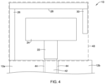
- Figure 4 is a schematic diagram of the illustrative dual band antenna 10 in which a physical footprint indicator 40 is shown in phantom around the dual band antenna 10.
- the physical footprint indicator 40 is intended to define what is considered to be the physical footprint or area of the dual band antenna 10.
- the physical footprint of the dual band antenna 10, as indicated by the physical footprint indicator 40 may be considered as being rectilinear, with a major dimension and a minor dimension that is orthogonal to the major dimension.
- a major dimension of the physical footprint may be less than about 15 millimeters. In some cases, the physical footprint may have a major dimension of less than about 10 millimeters and a minor dimension (orthogonal to the major dimension) that is less than about 8 millimeters.
- the dual band antenna 10 has a physical footprint, as indicated by the physical footprint indicator 40, of less than 200 square millimeters. In some instances, the dual band antenna 10 has a physical footprint, as indicated by the physical footprint indicator 40, of less than 100 square millimeters. In some instances, the dual band antenna 10 has a physical footprint, as indicated by the physical footprint indicator 40, of less than 75 square millimeters.
- Figure 5 is a graphical representation 50 of simulated antenna return loss data for the dual band antenna shown in Figure 2 .
- D1 is equal to 2.97 millimeters and D2 is equal to 1.5 millimeters
- D3 is equal to 7.1 millimeters and D4 is equal to 2.1 millimeters
- D5 is equal to 7.3 millimeters and D6 is 0.5 millimeters
- D7 is 9.8 millimeters and D8 is 0.8 millimeters
- D9 is 2.4 millimeters
- D10 is 0.8 millimeters and D11 is 0.55 millimeters.
- the first antenna element 18, the second antenna element 20 and the ground plane 12 are all formed on a common conductive layer patterned on an FR4 PCB layer that has a thickness of 1.6mm. It can be seen that there is a significant reduction in return loss at about 2.4 GHz and another significant reduction in return loss at about 5.4 GHz.
- Figure 6 is a graphical representation 60 of simulated antenna efficiency for the dual band antenna of Figure 5 , with the magnitude expressed in decibels (dB). It can be seen that there is a sharp increase in total efficiency around 2.4 GHz and a local maximum in total efficiency around 5.4 GHz.
- Figure 7 is a graphical representation 70 of simulated antenna efficiency for the dual band antenna of Figure 5 , with the magnitude expressed as a percentage (e.g. Energy Out/Energy In). It can be seen that there is a sharp increase in total efficiency around 2.4 GHz and a local maximum in total efficiency approaching 95% around 5.4 GHz.
- dB decibels
Landscapes
- Engineering & Computer Science (AREA)
- Computer Networks & Wireless Communication (AREA)
- Waveguide Aerials (AREA)
- Variable-Direction Aerials And Aerial Arrays (AREA)
- Support Of Aerials (AREA)
Abstract
Description
- The present disclosure pertains to antennas that may be used in a variety of wireless applications and more particularly pertains to dual band antennas having a small physical footprint.
- A variety of electronic devices utilize antennas for wirelessly transmitting and/or receiving information. In some cases, it may be desirable for an electronic device to have the capability of communicating over two or more different frequency bands. What would be desirable is a dual band antenna that can be easily and inexpensively incorporated into a variety of different electronic devices to support communication over each of two different frequency bands.
- This disclosure pertains to antennas that may be used in a variety of wireless applications and more particularly pertains to dual band antennas having a small physical footprint. An example may be found in a dual band antenna that includes a ground plane formed by a first conductive layer of a Printed Circuit Board (PCB). In this example, a first antenna element is formed by the first conductive layer of the PCB, where the first antenna element is spaced from and electrically isolated from the ground plane. The first antenna element is configured to resonate in a first frequency band. A second antenna element is also formed by the first conductive layer of the PCB. The second antenna element is electrically connected to the ground plane and electromagnetically coupled to the first antenna element. The second antenna element is configured to resonate in a second frequency band. The first antenna element and the second antenna element are configured to fit within a rectangular area of less than about 100 square millimeters on the PCB.
- Another example may be found in an antenna system. In this example, the antenna system includes a first antenna that is configured to resonate in a first frequency band and a second antenna that is configured to resonate in a second frequency band. The first antenna includes a base element having a major dimension of less than about 5 millimeters, and a cross element extending at least substantially orthogonally to the base element. The cross element is electrically connected with the base element and has a major dimension of less than about 10 millimeters. The base element is operatively coupled to a signal trace that is operatively coupled to an antenna driver and/or receiver. The example antenna system also includes a second antenna that is spaced from the first antenna and is configured to resonate in a second frequency band. The second antenna is electromagnetically coupled to the first antenna. The second antenna includes a first member extending at least substantially parallel with the base element of the first antenna and alongside a first end of the cross element of the first antenna. In this example, the first member has a major dimension of less than about 10 millimeters and is electrically connected to a ground plane. The second antenna further includes a second member that is electrically connected with the first member and extending along the cross element of the first antenna and at least substantially parallel with the major dimension of the cross element of the first antenna. The second member has a major dimension of less than about 15 millimeters. The second antenna further includes a third member that is electrically connected with the second member and extending at least substantially parallel with the first member of the first antenna and alongside a second end of the cross element opposite the first end. The third member has a major dimension that is less than the major dimension of the first member of the second antenna.
- Another example may be found in an antenna system that is formed by one or more layers of a Printed Circuit Board (PCB). The antenna system includes a first antenna element configured to resonate in a first frequency band centered at about 5.4 GHz and a second antenna element configured to resonate in a second frequency band centered at about 2.4 GHz. The first antenna element and the second antenna element may be electromagnetically coupled to one another and may fit within a rectangular area of less than about 100 square millimeters on the PCB. The first antenna element has a bandwidth of at least 2 GHz and the second antenna element has a bandwidth of at least 100 MHz, wherein the bandwidth is defined as having less than a -10 dB return loss within the band. In some cases, the first antenna element and the second antenna element, along with a ground plane, are patterned from a common conductive layer of the PCB, thereby forming a single conductive layer dual band antenna that has a small footprint and wide upper and lower frequency bands.
- The preceding summary is provided to facilitate an understanding of some of the features of the present disclosure and is not intended to be a full description. A full appreciation of the disclosure can be gained by taking the entire specification, claims, drawings, and abstract as a whole.
- The disclosure may be more completely understood in consideration of the following description of various illustrative embodiments of the disclosure in connection with the accompanying drawings, in which:
-
Figure 1 is a schematic diagram showing an illustrative dual band antenna; -
Figure 2 is a cross-sectional view taken along line 2-2 ofFigure 1 ; -
Figure 3 is a schematic diagram of the illustrative dual band antenna ofFigure 1 , with various dimensions denoted; -
Figure 4 is a schematic diagram of the illustrative dual band antenna ofFigure 1 , with its physical footprint denoted; -
Figure 5 is a graphical representation of simulated antenna return loss for the dual band antenna shown inFigure 2 , with the magnitude expressed in decibels (dB); -
Figure 6 is a graphical representation of simulated antenna efficiency for the dual band antenna ofFigure 5 , with the magnitude expressed in decibels (dB); and -
Figure 7 is a graphical representation of simulated antenna efficiency for the dual band antenna ofFigure 5 , with the magnitude expressed as a percentage. - While the disclosure is amenable to various modifications and alternative forms, specifics thereof have been shown by way of example in the drawings and will be described in detail. It should be understood, however, that the intention is not to limit aspects of the disclosure to the particular illustrative embodiments described. On the contrary, the intention is to cover all modifications, equivalents, and alternatives falling within the spirit and scope of the disclosure.
- The following description should be read with reference to the drawings wherein like reference numerals indicate like elements. The drawings, which are not necessarily to scale, are not intended to limit the scope of the disclosure. In some of the figures, elements not believed necessary to an understanding of relationships among illustrated components may have been omitted for clarity.
- All numbers are herein assumed to be modified by the term "about", unless the content clearly dictates otherwise. The term "about" means within a range of plus or minus 10 percent of the expressed number. The recitation of numerical ranges by endpoints includes all numbers subsumed within that range (e.g., 1 to 5 includes 1, 1.5, 2, 2.75, 3, 3.80, 4, and 5).
- As used in this specification and the appended claims, the singular forms "a", "an", and "the" include the plural referents unless the content clearly dictates otherwise. As used in this specification and the appended claims, the term "or" is generally employed in its sense including "and/or" unless the content clearly dictates otherwise.
- It is noted that references in the specification to "an embodiment", "some embodiments", "other embodiments", etc., indicate that the embodiment described may include a particular feature, structure, or characteristic, but every embodiment may not necessarily include the particular feature, structure, or characteristic. Moreover, such phrases are not necessarily referring to the same embodiment. Further, when a particular feature, structure, or characteristic is described in connection with an embodiment, it is contemplated that the feature, structure, or characteristic may be applied to other embodiments whether or not explicitly described unless clearly stated to the contrary.
-
Figure 1 is a schematic diagram of an illustrativedual band antenna 10 andFigure 2 is a cross-sectional view of thedual band antenna 10, taken along the line 2-2 ofFigure 1 . Thedual band antenna 10 includes aground plane 12 that, as seen inFigure 2 , is formed by a firstconductive layer 14 of a Printed Circuit Board (PCB) 16. In this example, a first antenna element 18 is also formed by the firstconductive layer 14 of thePCB 16, and is laterally spaced from and electrically isolated from theground plane 12 as shown inFigure 1 . The first antenna element 18 may be electrically coupled to a signal 23 that is driven and/or received by an antenna driver and/or receiver component. - In some instances, the first antenna element 18 may be configured to resonate in a first frequency band with a bandwidth of at least 2 GHz. As an example, the first frequency band may be centered at about 5.4 GHz. A
second antenna element 20 is also formed by the firstconductive layer 14 of thePCB 16. Thesecond antenna element 20 is electrically connected to theground plane 12 and is configured to be electrically isolated from but electromagnetically coupled to the first antenna element 18. In some instances, thesecond antenna element 20 may have a bandwidth of at least 100 MHz and may be considered as being configured to resonate in a second frequency band. As an example, the second frequency band may be centered at about 2.4 GHz. In some cases, the "bandwidth" of the first frequency band and the "bandwidth" of the second frequency band may be defined as having less than a -10 dB return loss within the band. - In some cases, a first frequency band that is centered at about 5.4 GHz may refer to a frequency band that is centered at 5.4 GHz ± 20 percent, or 5.4 GHz ± 10 percent. The first frequency band may range from about 5.15 GHz to about 5.85 GHz. A second frequency band that is centered at about 2.4 GHz may refer to a frequency band that is centered at 2.4 GHz ± 20 percent, or 2.4 GHz ± 10 percent. In some cases, the first frequency band may be suitable for WiFi communication, and the second frequency band may be suitable for WiFi and/or Bluetooth communication.
- In some instances, as shown in
Figure 1 , the first antenna element 18 may be considered as being T-shaped, with afirst member 22 forming a vertical (in the illustrated orientation) portion of the T and asecond member 24 that is orthogonal to the vertical portion (the first member 22). In some cases, thesecond antenna element 20 may be spaced from and may extend along at least part of at least three sides of thesecond member 24 of the first antenna element 18. In some instances, thesecond antenna element 20 includes athird member 26 that extends at least substantially parallel with thefirst member 22 of the first antenna element 18, afourth member 28 that is connected with thethird member 26 and extends at least substantially parallel with thesecond member 24 of the first antenna element 18, and afifth member 30 that is connected with thefourth member 28 and extends at least substantially parallel with thethird member 26. - As seen in
Figure 1 , theground plane 12 may be considered as being divided into afirst ground plane 12a and asecond ground plane 12b. In some cases, aconductive element 42 is electrically isolated from thefirst ground plane 12a and thesecond ground plane 12b via etchedareas 44. Theconductive layer 42 may be electrically coupled with thefirst member 22 of the first antenna element 18. - With particular attention to
Figure 2 , theillustrative PCB 16 may include a secondconductive layer 32 that is patterned on a second side of thePCB 16 opposite that of the firstconductive layer 14. In some cases, the secondconductive layer 32 may be electrically coupled with theconductive element 42, and hence with the first antenna element 18, by an electrically conductive via 34 that passes through aninsulative layer 36 of thePCB 16. In some cases, theinsulative layer 36 of thePCB 16 may have a thickness of 1.6 millimeters, and may be formed of, or otherwise include, FR4. FR4 is a fiberglass-reinforced epoxy laminate material, and is considered to be flame-retardant. FR-4 glass epoxy has a good strength to weight ratio. - In some cases, an
electrical device 38 may be coupled to the secondconductive layer 32. In some instances, theelectrical device 38 may be a transmitter and/or a receiver, and may include an electrical contact that is electrically coupled to the secondconductive layer 32, and thus electrically connected to the first antenna element 18 via theconductive element 42 and the conductive via 34. In some cases, theelectrical device 38 may include an impedance matching circuitry, filtering circuitry (e.g. bandpass filtering) and/or amplification circuitry, for example. - In some instances, a portion of the second
conductive layer 32, including theconductive element 42 and the conductive via 34, may be considered as having an impedance that matches that of thedual band antenna 10. This may help prevent signal reflections at the interface, thereby improving the effective antenna efficiency. As an example, the conductive path between theelectrical device 38 and a contact point of thedual band antenna 10 may represent a transmission line (e.g. co-planer microstrip line) that has an impedance of about 50 ohms, and thedual band antenna 10 may represent an impedance of about 50 ohms. -
Figure 3 is similar toFigure 1 , but labels a number of dimensions of thedual band antenna 10. With respect to the first antenna element 18, thefirst member 22 may be considered as being a base element while thesecond member 24 may be considered as being a cross element that extends at least substantially orthogonally to the base element. Thefirst member 22 may be considered as having a major dimension D1 that is less than about 5 millimeters and a minor dimension D2 that is less than about 2 millimeters. Thesecond member 24 may have a major dimension D3 that is less than about 10 millimeters and a minor dimension D4 that is less than about 4 millimeters. - With respect to the
second antenna element 20, thethird member 26 has a major dimension D5 of less than about 10 millimeters and a minor dimension D6 of less than 1 millimeter. Thefourth member 28 has a major dimension D7 of less than about 15 millimeters and a minor dimension D8 of less than about 1.5 millimeters. Thefifth member 30 has a major dimension D9 of less than D5 and a minor dimension D10 of less than 1.5 millimeters. In some cases, D9 may be about half of D5. In some cases, a spacing D11 between thesecond member 24 of the first antenna element 18 and thefifth member 30 of thesecond member 24 may influence the electromagnetic coupling between the first antenna element 18 and thesecond antenna element 20. - In a particular example, D1 is equal to 2.97 millimeters and D2 is equal to 1.5 millimeters, D3 is equal to 7.1 millimeters and D4 is equal to 2.1 millimeters, D5 is equal to 7.3 millimeters and D6 is 0.5 millimeters, D7 is 9.8 millimeters and D8 is 0.8 millimeters, D9 is 2.4 millimeters and D10 is 0.8 millimeters. In a particular example, D11 may be 0.55 millimeters. Other dimensions are also contemplated.
-
Figure 4 is a schematic diagram of the illustrativedual band antenna 10 in which aphysical footprint indicator 40 is shown in phantom around thedual band antenna 10. Thephysical footprint indicator 40 is intended to define what is considered to be the physical footprint or area of thedual band antenna 10. The physical footprint of thedual band antenna 10, as indicated by thephysical footprint indicator 40, may be considered as being rectilinear, with a major dimension and a minor dimension that is orthogonal to the major dimension. - In some cases, a major dimension of the physical footprint, as indicated by the
physical footprint indicator 40, may be less than about 15 millimeters. In some cases, the physical footprint may have a major dimension of less than about 10 millimeters and a minor dimension (orthogonal to the major dimension) that is less than about 8 millimeters. - In some instances, the
dual band antenna 10 has a physical footprint, as indicated by thephysical footprint indicator 40, of less than 200 square millimeters. In some instances, thedual band antenna 10 has a physical footprint, as indicated by thephysical footprint indicator 40, of less than 100 square millimeters. In some instances, thedual band antenna 10 has a physical footprint, as indicated by thephysical footprint indicator 40, of less than 75 square millimeters. -
Figure 5 is agraphical representation 50 of simulated antenna return loss data for the dual band antenna shown inFigure 2 . In this particular example, D1 is equal to 2.97 millimeters and D2 is equal to 1.5 millimeters, D3 is equal to 7.1 millimeters and D4 is equal to 2.1 millimeters, D5 is equal to 7.3 millimeters and D6 is 0.5 millimeters, D7 is 9.8 millimeters and D8 is 0.8 millimeters, D9 is 2.4 millimeters, D10 is 0.8 millimeters and D11 is 0.55 millimeters. Also, in this example, the first antenna element 18, thesecond antenna element 20 and theground plane 12 are all formed on a common conductive layer patterned on an FR4 PCB layer that has a thickness of 1.6mm. It can be seen that there is a significant reduction in return loss at about 2.4 GHz and another significant reduction in return loss at about 5.4 GHz. -
Figure 6 is agraphical representation 60 of simulated antenna efficiency for the dual band antenna ofFigure 5 , with the magnitude expressed in decibels (dB). It can be seen that there is a sharp increase in total efficiency around 2.4 GHz and a local maximum in total efficiency around 5.4 GHz.Figure 7 is agraphical representation 70 of simulated antenna efficiency for the dual band antenna ofFigure 5 , with the magnitude expressed as a percentage (e.g. Energy Out/Energy In). It can be seen that there is a sharp increase in total efficiency around 2.4 GHz and a local maximum in total efficiency approaching 95% around 5.4 GHz. - It should be understood that this disclosure is, in many respects, only illustrative. Changes may be made in details, particularly in matters of shape, size, and arrangement of steps without exceeding the scope of the disclosure. This may include, to the extent that it is appropriate, the use of any of the features of one example embodiment being used in other embodiments.
Claims (15)
- A dual band antenna, comprising:a ground plane formed by a first conductive layer of a Printed Circuit Board (PCB);a first antenna element formed by the first conductive layer of the PCB, the first antenna element is spaced from and electrically isolated from the ground plane, the first antenna element is configured to resonate in a first frequency band;a second antenna element formed by the first conductive layer of the PCB, the second antenna element is electrically connected to the ground plane and electromagnetically coupled to the first antenna element, the second antenna element is configured to resonate in a second frequency band; andwherein the first antenna element and the second antenna element fit within a rectangular area of less than about 100 square millimeters on the PCB.
- The dual band antenna of claim 1, wherein the first antenna element and the second antenna element fit within a rectangular area of less than about 75 square millimeters on the PCB.
- The dual band antenna of claim 1, wherein the first frequency band is centered at about 5.4 GHz.
- The dual band antenna of claim 1, wherein the second frequency band is centered at about 2.4 GHz.
- The dual band antenna of claim 1, wherein the first antenna element is T-shaped, with a first member forming a vertical portion of the T and a second member orthogonal to the vertical portion of the T, the second antenna element is spaced from and extends along at least part of at least three sides of the second member of the first antenna element.
- The dual band antenna of claim 1, wherein:the first antenna element is T-shaped, with a first member forming a vertical portion of the T and a second member orthogonal to the vertical portion of the T;the second antenna element comprises:a third member extending at least substantially parallel with the first member of the first antenna element;a fourth member connected with the third member and extending at least substantially parallel with the second member of the first antenna element;a fifth member connected with the fourth member and extending at least substantially parallel with the third member; andwherein the second antenna element extends at least partially around at least part of at least three sides of the second member of the first antenna element.
- The dual band antenna of claim 6, wherein a spacing between the second member of the first antenna element and the fifth member of the second antenna element influences the electromagnetic coupling between the first antenna element and the second antenna element.
- The dual band antenna of claim 1, wherein:the first antenna element comprises:a base element having a major dimension of less than about 5 millimeters, the base element operatively coupled to a signal trace;a cross element extending at least substantially orthogonally to the base element, the cross element electrically connected with the base element, the cross element having a major dimension of less than about 10 millimeters;the second antenna element comprises:a first member extending at least substantially parallel with the base element of the first antenna element and alongside a first end of the cross element, the first member having a major dimension of less than about 10 millimeters, the first member electrically connected to the ground plane;a second member electrically connected with the first member and extending along the cross element and at least substantially parallel with the major dimension of the cross element of the first antenna element, the second member having a major dimension of less than about 15 millimeters; anda third member electrically connected with the second member and extending at least substantially parallel with the first member and alongside a second end of the cross element opposite the first end, the third member having a major dimension that is less than the major dimension of the first member of the second antenna element.
- The dual band antenna of claim 8, wherein:the base element of the first antenna element has a minor dimension of less than about 2 millimeters; andthe cross element of the first antenna element has a minor dimension along the first end and the second end of less than about 4 millimeters.
- The dual band antenna of claim 8, wherein:the first member of the second antenna element has a minor dimension of less than about 1 millimeter;the second member of the second antenna element has a minor dimension of less than about 1.5 millimeters; andthe third member of the second antenna element has a minor dimension of less than about 1.5 millimeters.
- The dual band antenna of claim 8, wherein:the first antenna element is electrically isolated from the ground plane; andthe second antenna element is electromagnetic coupled to the first antenna element via an electromagnetic field.
- The dual band antenna of claim 8, wherein the first antenna element and the second antenna element fit within a rectangular area of less than about 200 square millimeters.
- The dual band antenna of claim 8, wherein the first antenna element and the second antenna element fit within a rectangular area of less than about 75 square millimeters.
- The dual band antenna of claim 1, wherein:the first frequency band is centered at about 5.4 GHz;the second frequency band is centered at about 2.4 GHz; andthe first frequency band has a bandwidth of at least 2 GHz and the second frequency band has a bandwidth of at least 100 MHz, wherein the bandwidth is defined as having less than a -10 dB return loss within the band.
- The dual band antenna of claim 1, wherein the first frequency band has a bandwidth of at least 2 GHz and the second frequency band has a bandwidth of at least 100 MHz, wherein the bandwidth is defined as having less than a -10 dB return loss within the band.
Applications Claiming Priority (1)
| Application Number | Priority Date | Filing Date | Title |
|---|---|---|---|
| US18/160,065 US12431621B2 (en) | 2023-01-26 | 2023-01-26 | Compact dual band antenna |
Publications (2)
| Publication Number | Publication Date |
|---|---|
| EP4407799A1 true EP4407799A1 (en) | 2024-07-31 |
| EP4407799B1 EP4407799B1 (en) | 2026-03-04 |
Family
ID=89619316
Family Applications (1)
| Application Number | Title | Priority Date | Filing Date |
|---|---|---|---|
| EP24151591.5A Active EP4407799B1 (en) | 2023-01-26 | 2024-01-12 | Compact dual band antenna |
Country Status (2)
| Country | Link |
|---|---|
| US (2) | US12431621B2 (en) |
| EP (1) | EP4407799B1 (en) |
Families Citing this family (2)
| Publication number | Priority date | Publication date | Assignee | Title |
|---|---|---|---|---|
| US12431621B2 (en) * | 2023-01-26 | 2025-09-30 | Honeywell International Inc. | Compact dual band antenna |
| US12695189B2 (en) | 2024-01-11 | 2026-07-28 | Honeywell International Inc. | Printed circuit board implemented multiband antenna |
Citations (3)
| Publication number | Priority date | Publication date | Assignee | Title |
|---|---|---|---|---|
| US20040196188A1 (en) * | 2003-04-01 | 2004-10-07 | D-Link Corporation | Planar double l-shaped antenna of dual frequency |
| US10044101B1 (en) * | 2014-02-09 | 2018-08-07 | Redpine Signals, Inc. | Triple frequency band compact printed circuit antenna for WLAN |
| CN108987919A (en) * | 2018-07-24 | 2018-12-11 | 西安电子科技大学 | A kind of polygon ultra-wideband antenna of compact unsymmetric structure |
Family Cites Families (693)
| Publication number | Priority date | Publication date | Assignee | Title |
|---|---|---|---|---|
| US191512A (en) | 1877-06-05 | Improvement in ventilation and disinfection of buildings | ||
| US2016004A (en) | 1929-08-02 | 1935-10-01 | Gen Cable Corp | Electric cable installation |
| GB1488513A (en) | 1974-04-26 | 1977-10-12 | Howorth Air Eng Ltd | Clean air zone |
| US3974492A (en) | 1974-05-07 | 1976-08-10 | Fahir Girismen | Alarm system |
| US4046532A (en) | 1976-07-14 | 1977-09-06 | Honeywell Inc. | Refrigeration load shedding control device |
| US4341345A (en) | 1980-02-19 | 1982-07-27 | Honeywell Inc. | Method and apparatus for power load shedding |
| SE450299B (en) | 1980-03-21 | 1987-06-15 | Philips Nv | PROCEDURE AND DEVICE FOR OPERATING A DEVICE IN THE EVENT OF ELECTRICAL INTERRUPTION |
| US4345162A (en) | 1980-06-30 | 1982-08-17 | Honeywell Inc. | Method and apparatus for power load shedding |
| US4375637A (en) | 1981-02-24 | 1983-03-01 | Firecom, Inc. | Integrated alarm, security, building management, and communications system |
| US4389577A (en) | 1982-04-14 | 1983-06-21 | Honeywell Inc. | Apparatus for power load-shedding with auxiliary commandable thermostat |
| US4523295A (en) | 1982-09-07 | 1985-06-11 | Zenith Electronics Corporation | Power loss compensation for programmable memory control system |
| US4531214A (en) | 1983-05-24 | 1985-07-23 | United Technologies Corporation | Power loss analyzer circuit |
| US4644320A (en) | 1984-09-14 | 1987-02-17 | Carr R Stephen | Home energy monitoring and control system |
| US4577977A (en) | 1985-04-01 | 1986-03-25 | Honeywell Inc. | Energy submetering system |
| NL8701557A (en) | 1987-07-02 | 1989-02-01 | Skf Ind Trading & Dev | METHOD AND APPARATUS FOR EXAMINING WEAR AND FRICTION PROPERTIES OF TREATMENT MATERIALS WITH SLIDING FRICTION. |
| JPH07118826B2 (en) | 1987-09-23 | 1995-12-18 | 山武ハネウエル株式会社 | Building management system |
| US4924404A (en) | 1988-04-11 | 1990-05-08 | K. Reinke, Jr. & Company | Energy monitor |
| US5012406A (en) | 1988-04-19 | 1991-04-30 | Power Card Supply | Line of power interruption in predetermined area of internal permanent memory |
| US6005576A (en) | 1989-09-29 | 1999-12-21 | Hitachi, Ltd. | Method for visual programming with aid of animation |
| US5553094A (en) | 1990-02-15 | 1996-09-03 | Iris Systems, Inc. | Radio communication network for remote data generating stations |
| US5793125A (en) | 1991-02-25 | 1998-08-11 | Tarng; Min Ming | Smart integrated socket automation system |
| US5315533A (en) | 1991-05-17 | 1994-05-24 | Best Power Technology, Inc. | Back-up uninterruptible power system |
| CA2116168A1 (en) | 1993-03-02 | 1994-09-03 | Gregory Cmar | Process for identifying patterns of electric energy consumption and demand in a facility, predicting and verifying the effects of proposed changes, and implementing such changes in the facility to conserve energy |
| US5621256A (en) | 1993-04-20 | 1997-04-15 | Molex Incorporated | Hysteresis in a circuit for sensing presence of a plug |
| JP3866300B2 (en) | 1993-07-20 | 2007-01-10 | 三菱電機株式会社 | Building management equipment |
| US5519295A (en) | 1994-04-06 | 1996-05-21 | Honeywell Inc. | Electrically operated actuator having a capacitor storing energy for returning the actuator to a preferred position upon power failure |
| EP0681232B1 (en) | 1994-05-03 | 2001-08-01 | Yamatake Corporation | Set value learning apparatus including neural network. |
| US5493191A (en) | 1994-09-19 | 1996-02-20 | Eaton Corporation | B-type actuator with time out |
| US5598349A (en) | 1994-10-25 | 1997-01-28 | Honeywell Inc. | Responding to pricing signals from a power supplier using mixed add/shed and profile setback delta schemes |
| US6574581B1 (en) | 1994-10-25 | 2003-06-03 | Honeywell International Inc. | Profile based method for deriving a temperature setpoint using a ‘delta’ based on cross-indexing a received price-point level signal |
| US5572438A (en) | 1995-01-05 | 1996-11-05 | Teco Energy Management Services | Engery management and building automation system |
| US5729471A (en) | 1995-03-31 | 1998-03-17 | The Regents Of The University Of California | Machine dynamic selection of one video camera/image of a scene from multiple video cameras/images of the scene in accordance with a particular perspective on the scene, an object in the scene, or an event in the scene |
| US20030083957A1 (en) | 1995-06-16 | 2003-05-01 | Shari B. Olefson | Method and apparatus for selection and viewing real estate properties |
| US5727579A (en) | 1996-05-29 | 1998-03-17 | 144 Limited Partnership | Automatic hand washing and drying apparatus including combined blow drying means and towel dispensing means |
| CN1169032C (en) | 1996-11-29 | 2004-09-29 | 松下电工株式会社 | Building automation system |
| US6139177A (en) | 1996-12-03 | 2000-10-31 | Hewlett Packard Company | Device access and control using embedded web access functionality |
| US5777598A (en) | 1996-12-30 | 1998-07-07 | Honeywell Inc. | Computer-generated display permitting alignment of one scale of each of a plurality of graphs |
| US5973662A (en) | 1997-04-07 | 1999-10-26 | Johnson Controls Technology Company | Analog spectrum display for environmental control |
| AU7387098A (en) | 1997-05-14 | 1998-12-08 | Lamar Corporation, The | Combination electrical multi-strip receptacle with timer and enclosure |
| US6218995B1 (en) | 1997-06-13 | 2001-04-17 | Itron, Inc. | Telemetry antenna system |
| JPH1124735A (en) | 1997-06-27 | 1999-01-29 | Mitsubishi Electric Corp | Plant operation support system |
| US6249100B1 (en) | 1997-07-31 | 2001-06-19 | Honeywell International Inc. | Drive circuit and method for an electric actuator with spring return |
| US6078970A (en) | 1997-10-15 | 2000-06-20 | International Business Machines Corporation | System for determining adapter interrupt status where interrupt is sent to host after operating status stored in register is shadowed to host memory |
| US6262685B1 (en) | 1997-10-24 | 2001-07-17 | Itron, Inc. | Passive radiator |
| US5990932A (en) | 1997-12-22 | 1999-11-23 | Northern Telecom, Limited | Collaborative shared space |
| US6532195B1 (en) | 1998-04-03 | 2003-03-11 | General Electric Company | Clock saver apparatus and methods |
| CA2236063C (en) | 1998-04-28 | 2005-07-12 | Ibm Canada Limited-Ibm Canada Limitee | Multi-variable graphical interface and method |
| US6229429B1 (en) | 1998-05-15 | 2001-05-08 | Daniel J. Horon | Fire protection and security monitoring system |
| US6065842A (en) | 1998-05-22 | 2000-05-23 | Raytheon Company | Heat maps for controlling deformations in optical components |
| US6122603A (en) | 1998-05-29 | 2000-09-19 | Powerweb, Inc. | Multi-utility energy control system with dashboard |
| US7023440B1 (en) | 1998-09-14 | 2006-04-04 | Fisher Rosemount Systems, Inc. | Methods and apparatus for integrated display of process events and trend data |
| US6353853B1 (en) | 1998-10-26 | 2002-03-05 | Triatek, Inc. | System for management of building automation systems through an HTML client program |
| US6157943A (en) | 1998-11-12 | 2000-12-05 | Johnson Controls Technology Company | Internet access to a facility management system |
| US6885185B1 (en) | 1998-12-01 | 2005-04-26 | Itron Electricity Metering, Inc. | Modular meter configuration and methodology |
| US6442507B1 (en) | 1998-12-29 | 2002-08-27 | Wireless Communications, Inc. | System for creating a computer model and measurement database of a wireless communication network |
| US6598056B1 (en) | 1999-02-12 | 2003-07-22 | Honeywell International Inc. | Remotely accessible building information system |
| US6222714B1 (en) | 1999-05-17 | 2001-04-24 | Gary R. Hoffman | Microprocessor based setting group controller for protective relay operations |
| US6238337B1 (en) | 1999-07-09 | 2001-05-29 | International Business Machines Corporation | Medical non-intrusive prevention based on network of embedded systems |
| US6473084B1 (en) | 1999-09-08 | 2002-10-29 | C4Cast.Com, Inc. | Prediction input |
| US6375038B1 (en) | 1999-10-28 | 2002-04-23 | Daansen Usa, Inc. | Dispenser having timing means, multisensory output and means of tracking usage number |
| US6727818B1 (en) | 1999-10-29 | 2004-04-27 | Hill-Rom Services, Inc. | Hygiene monitoring system |
| JP3548065B2 (en) | 1999-11-15 | 2004-07-28 | インターナショナル・ビジネス・マシーンズ・コーポレーション | Remote control system, server / client system, product terminal device control server, product terminal device operation method, device information sharing method, and storage medium |
| US7231327B1 (en) | 1999-12-03 | 2007-06-12 | Digital Sandbox | Method and apparatus for risk management |
| US6816878B1 (en) | 2000-02-11 | 2004-11-09 | Steven L. Zimmers | Alert notification system |
| US6421571B1 (en) | 2000-02-29 | 2002-07-16 | Bently Nevada Corporation | Industrial plant asset management system: apparatus and method |
| US6801199B1 (en) | 2000-03-01 | 2004-10-05 | Foliofn, Inc. | Method and apparatus for interacting with investors to create investment portfolios |
| ATE303618T1 (en) | 2000-03-10 | 2005-09-15 | Smiths Detection Inc | CONTROL FOR AN INDUSTRIAL PROCESS WITH ONE OR MORE MULTIDIMENSIONAL VARIABLES |
| GB2366640B (en) | 2000-03-30 | 2004-12-29 | Ibm | Distribution of activation information |
| US6580950B1 (en) | 2000-04-28 | 2003-06-17 | Echelon Corporation | Internet based home communications system |
| US6995768B2 (en) | 2000-05-10 | 2006-02-07 | Cognos Incorporated | Interactive business data visualization system |
| JP2001356813A (en) | 2000-06-14 | 2001-12-26 | Chiyoda Corp | Plant maintenance support system |
| US6429868B1 (en) | 2000-07-13 | 2002-08-06 | Charles V. Dehner, Jr. | Method and computer program for displaying quantitative data |
| US7062722B1 (en) | 2000-08-22 | 2006-06-13 | Bruce Carlin | Network-linked interactive three-dimensional composition and display of saleable objects in situ in viewer-selected scenes for purposes of promotion and procurement |
| US6911177B2 (en) | 2000-09-19 | 2005-06-28 | Jeffrey L. Deal | Ultraviolet area sterilizer and method of area sterilization using ultraviolet radiation |
| US6720874B2 (en) | 2000-09-29 | 2004-04-13 | Ids Systems, Inc. | Portal intrusion detection apparatus and method |
| WO2002035909A2 (en) | 2000-11-03 | 2002-05-10 | Siemens Corporate Research, Inc. | Video-supported planning and design with physical marker objects sign |
| US20020130868A1 (en) | 2000-11-28 | 2002-09-19 | Aston Guardian Limited | Method and apparatus for providing financial instrument interface |
| US7061393B2 (en) | 2000-12-20 | 2006-06-13 | Inncom International Inc. | System and method for managing services and facilities in a multi-unit building |
| US7302313B2 (en) | 2001-02-07 | 2007-11-27 | Aircuity, Inc. | Air quality monitoring systems and methods |
| US20020111698A1 (en) | 2001-02-09 | 2002-08-15 | Marco Graziano | Web-based system for monitoring and/or controlling home devices |
| US6552525B2 (en) | 2001-03-14 | 2003-04-22 | General Electric Company | System and method for scheduling and monitoring electrical device usage |
| US20030030637A1 (en) | 2001-04-20 | 2003-02-13 | Grinstein Georges G. | Method and system for data analysis |
| NZ529174A (en) | 2001-05-02 | 2007-02-23 | Bp Corp North America Inc | Method and an unleaded low emission gasoline for fuelling an automotive engine with reduced emissions |
| US6791458B2 (en) | 2001-05-22 | 2004-09-14 | Hubbell Incorporated | Dual technology occupancy sensor and method for using the same |
| US6741915B2 (en) | 2001-08-22 | 2004-05-25 | Mmi Controls, Ltd. | Usage monitoring HVAC control system |
| US6993417B2 (en) | 2001-09-10 | 2006-01-31 | Osann Jr Robert | System for energy sensing analysis and feedback |
| US20030179149A1 (en) | 2001-11-26 | 2003-09-25 | Schlumberger Electricity, Inc. | Embedded antenna apparatus for utility metering applications |
| US7356548B1 (en) | 2001-12-03 | 2008-04-08 | The Texas A&M University System | System and method for remote monitoring and controlling of facility energy consumption |
| US20030103075A1 (en) | 2001-12-03 | 2003-06-05 | Rosselot Robert Charles | System and method for control of conference facilities and equipment |
| US7096125B2 (en) | 2001-12-17 | 2006-08-22 | Honeywell International Inc. | Architectures of sensor networks for biological and chemical agent detection and identification |
| CN100356699C (en) | 2002-01-09 | 2007-12-19 | 松下电器产业株式会社 | Equipment data collecting system |
| US6619555B2 (en) | 2002-02-13 | 2003-09-16 | Howard B. Rosen | Thermostat system communicating with a remote correspondent for receiving and displaying diverse information |
| US20030158975A1 (en) | 2002-02-15 | 2003-08-21 | Tridium | Real-time data interface and method for browsers and the like |
| US20030171851A1 (en) | 2002-03-08 | 2003-09-11 | Peter J. Brickfield | Automatic energy management and energy consumption reduction, especially in commercial and multi-building systems |
| WO2003082351A2 (en) | 2002-03-22 | 2003-10-09 | Path-X International, Inc. | Hand-washing monitoring system |
| KR100701110B1 (en) | 2002-03-28 | 2007-03-30 | 로버트쇼 컨트롤즈 캄파니 | Energy management system and method |
| US20040030531A1 (en) | 2002-03-28 | 2004-02-12 | Honeywell International Inc. | System and method for automated monitoring, recognizing, supporting, and responding to the behavior of an actor |
| JP2003333584A (en) | 2002-05-16 | 2003-11-21 | Fujitsu Ltd | Monitoring system |
| US20030233432A1 (en) | 2002-06-18 | 2003-12-18 | John Davis | Web-based interface for building management systems |
| US20040143474A1 (en) | 2002-07-27 | 2004-07-22 | Brad Haeberle | Method and system for obtaining service information about a building site |
| US6907387B1 (en) | 2002-08-05 | 2005-06-14 | Bellsouth Intellectual Property Corporation | Systems and methods for remote monitoring of a facility location |
| JP2004096341A (en) | 2002-08-30 | 2004-03-25 | Fujitsu Ltd | Antenna device including inverted F-type antenna with variable resonance frequency |
| US6796896B2 (en) | 2002-09-19 | 2004-09-28 | Peter J. Laiti | Environmental control unit, and air handling systems and methods using same |
| US7058524B2 (en) | 2002-10-25 | 2006-06-06 | Hudson Bay Wireless, Llc | Electrical power metering system |
| GB0301790D0 (en) | 2003-01-25 | 2003-02-26 | Ubiquitous Systems Ltd | System for detecting intruders in a populated space |
| US7584165B2 (en) | 2003-01-30 | 2009-09-01 | Landmark Graphics Corporation | Support apparatus, method and system for real time operations and maintenance |
| JP2005165676A (en) | 2003-12-02 | 2005-06-23 | Mitsubishi Heavy Ind Ltd | Facility management system and facility management method |
| US6931445B2 (en) | 2003-02-18 | 2005-08-16 | Statsignal Systems, Inc. | User interface for monitoring remote devices |
| US20040168115A1 (en) | 2003-02-21 | 2004-08-26 | Bauernschmidt Bill G. | Method and system for visualizing data from multiple, cached data sources with user defined treemap reports |
| US7110843B2 (en) | 2003-02-24 | 2006-09-19 | Smar Research Corporation | Arrangements and methods for monitoring processes and devices using a web service |
| US20040260411A1 (en) | 2003-02-25 | 2004-12-23 | Cannon Joel R. | Consumer energy services web-enabled software and method |
| US7750908B2 (en) | 2003-04-04 | 2010-07-06 | Agilent Technologies, Inc. | Focus plus context viewing and manipulation of large collections of graphs |
| US7596473B2 (en) | 2003-05-20 | 2009-09-29 | Interlego Ag | Method of constructing a virtual construction model |
| US20040233192A1 (en) | 2003-05-22 | 2004-11-25 | Hopper Stephen A. | Focally-controlled imaging system and method |
| US7222800B2 (en) | 2003-08-18 | 2007-05-29 | Honeywell International Inc. | Controller customization management system |
| ES2353958T3 (en) | 2003-08-27 | 2011-03-08 | ZAKRYTOE AKTIONERNOE OBSCHESTVO PROIZVODSTVENNO-VNEDRENCHESKOE PREDPRIYATIE "AMULET" | METHOD FOR DESIGNING AN INTEGRATED SECURITY SYSTEM FOR AN INSTALLATION. |
| US7129900B2 (en) | 2003-09-08 | 2006-10-31 | Tantalus Systems Corp. | Meter antenna |
| US7043380B2 (en) | 2003-09-16 | 2006-05-09 | Rodenberg Iii Ernest Adolph | Programmable electricity consumption monitoring system and method |
| US8151280B2 (en) | 2003-10-27 | 2012-04-03 | Microsoft Corporation | Simple and dynamic configuration of network devices |
| GB0325504D0 (en) | 2003-10-31 | 2003-12-03 | Leach John | Security engineering: A process for developing accurate and reliable security systems |
| US7167777B2 (en) | 2003-11-04 | 2007-01-23 | Powerweb Technologies | Wireless internet lighting control system |
| WO2005055014A2 (en) | 2003-12-01 | 2005-06-16 | Colorado Vnet, Llc | Configuration application for building automation |
| US20050143863A1 (en) | 2003-12-19 | 2005-06-30 | Margaret Ruane | Building control system field panel having integrated web server |
| US7317404B2 (en) | 2004-01-14 | 2008-01-08 | Itron, Inc. | Method and apparatus for collecting and displaying consumption data from a meter reading system |
| US7209096B2 (en) | 2004-01-22 | 2007-04-24 | Antenex, Inc. | Low visibility dual band antenna with dual polarization |
| US7447333B1 (en) | 2004-01-22 | 2008-11-04 | Siemens Corporate Research, Inc. | Video and audio monitoring for syndromic surveillance for infectious diseases |
| US7557729B2 (en) | 2004-02-05 | 2009-07-07 | Ecologic Analytics, LLC | Method and system for validation, estimation and editing of daily meter read data |
| WO2005079340A2 (en) | 2004-02-13 | 2005-09-01 | Lacasse Photoplastics, Inc. | Intelligent directional fire alarm system |
| JP2005242531A (en) | 2004-02-25 | 2005-09-08 | Hitachi Ltd | Installation work management system using 3D-CAD |
| US20050194456A1 (en) | 2004-03-02 | 2005-09-08 | Tessier Patrick C. | Wireless controller with gateway |
| US7183899B2 (en) | 2004-03-15 | 2007-02-27 | Global Gate Technologies, Inc. | Remotely monitored and controlled building automation system |
| US7383148B2 (en) | 2004-03-25 | 2008-06-03 | Siemens Building Technologies, Inc. | Method and apparatus for graphically displaying a building system |
| US7512450B2 (en) | 2004-03-25 | 2009-03-31 | Siemens Building Technologies, Inc. | Method and apparatus for generating a building system model |
| US7548833B2 (en) | 2004-03-25 | 2009-06-16 | Siemens Building Technologies, Inc. | Method and apparatus for graphical display of a condition in a building system with a mobile display unit |
| US7610910B2 (en) | 2004-03-25 | 2009-11-03 | Siemens Building Technologies, Inc. | Method and apparatus for controlling building component characteristics |
| WO2005096738A2 (en) | 2004-03-30 | 2005-10-20 | Igenus, Inc. | Method and system for organizing data relating to a home |
| JP2005311563A (en) | 2004-04-20 | 2005-11-04 | Victor Co Of Japan Ltd | Monitoring method |
| US7031880B1 (en) | 2004-05-07 | 2006-04-18 | Johnson Controls Technology Company | Method and apparatus for assessing performance of an environmental control system |
| US7477148B2 (en) | 2004-06-01 | 2009-01-13 | Airborne Health, Inc | Soap dispenser and method for assuring clean hands |
| US8041744B2 (en) | 2004-06-24 | 2011-10-18 | Tekla Corporation | Computer-aided modeling |
| US7490295B2 (en) | 2004-06-25 | 2009-02-10 | Apple Inc. | Layer for accessing user interface elements |
| US8302020B2 (en) | 2004-06-25 | 2012-10-30 | Apple Inc. | Widget authoring and editing environment |
| US20060009862A1 (en) | 2004-06-28 | 2006-01-12 | Raphael Imhof | Method and apparatus for accessing a building system model |
| US20060016201A1 (en) | 2004-07-20 | 2006-01-26 | National Environmental Products, Ltd. | Actuator alarm for critical environments or applications |
| KR100786703B1 (en) | 2004-07-24 | 2007-12-21 | 삼성전자주식회사 | Device and method for measuring physical exercise using acceleration sensor |
| US8289390B2 (en) | 2004-07-28 | 2012-10-16 | Sri International | Method and apparatus for total situational awareness and monitoring |
| JP2006054504A (en) | 2004-08-09 | 2006-02-23 | Olympus Corp | Image generating method and apparatus |
| WO2006137829A2 (en) | 2004-08-10 | 2006-12-28 | Sarnoff Corporation | Method and system for performing adaptive image acquisition |
| US7372373B2 (en) | 2004-08-27 | 2008-05-13 | Itron, Inc. | Embedded antenna and filter apparatus and methodology |
| US7295116B2 (en) | 2004-09-01 | 2007-11-13 | Microsoft Corporation | Architecture, programming model and API'S |
| US7308323B2 (en) | 2004-09-10 | 2007-12-11 | Siemens Building Technologies, Inc. | Configuration output system |
| US20060058900A1 (en) | 2004-09-10 | 2006-03-16 | Johanson Thomas E | User interface for a building control system configurator |
| US7280030B1 (en) | 2004-09-24 | 2007-10-09 | Sielox, Llc | System and method for adjusting access control based on homeland security levels |
| US8312549B2 (en) | 2004-09-24 | 2012-11-13 | Ygor Goldberg | Practical threat analysis |
| US20060067546A1 (en) | 2004-09-27 | 2006-03-30 | Kimberly-Clark Worldwide, Inc. | Device for encouraging hand wash compliance |
| US20060067545A1 (en) | 2004-09-27 | 2006-03-30 | Kimberly-Clark Worldwide, Inc. | Device for encouraging hand wash compliance |
| US7292908B2 (en) | 2004-10-13 | 2007-11-06 | Robotic Built Structures, Inc. | Systems and methods for manufacturing customized prefabricated buildings including arbitrarily modularizing a building specification without using any pre-defined modules |
| US7453373B2 (en) | 2004-10-29 | 2008-11-18 | Itron, Inc. | Integrated meter module and utility metering system |
| US6990335B1 (en) | 2004-11-18 | 2006-01-24 | Charles G. Shamoon | Ubiquitous connectivity and control system for remote locations |
| US7149645B2 (en) | 2004-12-30 | 2006-12-12 | Intel Corporation | Method and apparatus for accurate on-die temperature measurement |
| US7228234B2 (en) | 2005-01-26 | 2007-06-05 | Siemens Building Technologies, Inc. | Weather data quality control and ranking method |
| US6993403B1 (en) | 2005-03-22 | 2006-01-31 | Praxair Technology, Inc. | Facility monitoring method |
| US20060265664A1 (en) | 2005-05-17 | 2006-11-23 | Hitachi, Ltd. | System, method and computer program product for user interface operations for ad-hoc sensor node tracking |
| US20060284784A1 (en) | 2005-06-17 | 2006-12-21 | Norman Smith | Universal antenna housing |
| US7434742B2 (en) | 2005-06-20 | 2008-10-14 | Emerson Electric Co. | Thermostat capable of displaying received information |
| US7904186B2 (en) | 2005-08-22 | 2011-03-08 | Trane International, Inc. | Building automation system facilitating user customization |
| US8099178B2 (en) | 2005-08-22 | 2012-01-17 | Trane International Inc. | Building automation system facilitating user customization |
| US7917232B2 (en) | 2005-08-22 | 2011-03-29 | Trane International Inc. | Building automation system data management |
| US8024054B2 (en) | 2005-08-22 | 2011-09-20 | Trane International, Inc. | Building automation system facilitating user customization |
| US7720306B2 (en) | 2005-08-29 | 2010-05-18 | Photomed Technologies, Inc. | Systems and methods for displaying changes in biological responses to therapy |
| US7142123B1 (en) | 2005-09-23 | 2006-11-28 | Lawrence Kates | Method and apparatus for detecting moisture in building materials |
| US7734451B2 (en) | 2005-10-18 | 2010-06-08 | Honeywell International Inc. | System, method, and computer program for early event detection |
| US7378969B2 (en) | 2005-10-25 | 2008-05-27 | Sap Ag | Systems and methods for visualizing auto-id data |
| US7743336B2 (en) | 2005-10-27 | 2010-06-22 | Apple Inc. | Widget security |
| US7603222B2 (en) | 2005-11-18 | 2009-10-13 | General Electric Company | Sensor diagnostics using embedded model quality parameters |
| US20070114295A1 (en) | 2005-11-22 | 2007-05-24 | Robertshaw Controls Company | Wireless thermostat |
| AU2005239620B2 (en) | 2005-11-28 | 2011-04-28 | Enermet Ag | Control apparatus for deactivating an electrical load during congestion periods |
| US7761310B2 (en) | 2005-12-09 | 2010-07-20 | Samarion, Inc. | Methods and systems for monitoring quality and performance at a healthcare facility |
| PL1982314T3 (en) | 2006-02-10 | 2011-05-31 | Kieran Richard Hyland | A system and method for monitoring hygiene standards compliance |
| US7492372B2 (en) | 2006-02-21 | 2009-02-17 | Bio-Rad Laboratories, Inc. | Overlap density (OD) heatmaps and consensus data displays |
| US7392115B2 (en) | 2006-03-01 | 2008-06-24 | Honeywell International Inc. | Characterization of utility demand using utility demand footprint |
| US20070216682A1 (en) | 2006-03-15 | 2007-09-20 | Honeywell International Inc. | Method and apparatus for displaying three dimensions of data in a trend plot |
| US7567844B2 (en) | 2006-03-17 | 2009-07-28 | Honeywell International Inc. | Building management system |
| US20070239484A1 (en) | 2006-03-20 | 2007-10-11 | Arond Betty J | System and method for managing patient bed assignments, bed occupancy, and staffing in a healthcare facility operation |
| US8118240B2 (en) | 2006-04-20 | 2012-02-21 | Masco Corporation Of Indiana | Pull-out wand |
| CN2906952Y (en) | 2006-04-27 | 2007-05-30 | 汉达精密电子(昆山)有限公司 | Dual-frequency PCB antenna using circular column type oscillator |
| US8103389B2 (en) | 2006-05-18 | 2012-01-24 | Gridpoint, Inc. | Modular energy control system |
| US7646294B2 (en) | 2006-05-22 | 2010-01-12 | Honeywell International Inc. | Alarm maps to facilitate root cause analysis through spatial and pattern recognition |
| TW200745996A (en) | 2006-05-24 | 2007-12-16 | Objectvideo Inc | Intelligent imagery-based sensor |
| TW200746546A (en) * | 2006-06-09 | 2007-12-16 | Advanced Connectek Inc | Multi-frequency antenna with dual loops |
| EP2400359B1 (en) | 2006-06-23 | 2014-07-02 | Saudi Arabian Oil Company | System, method, and program product for targeting and optimal driving force distribution in energy recovery systems |
| US20080001763A1 (en) | 2006-06-29 | 2008-01-03 | Raja Vishnu R | Hand washing compliance system |
| US8024666B2 (en) | 2006-06-30 | 2011-09-20 | Business Objects Software Ltd. | Apparatus and method for visualizing data |
| KR20080002346A (en) | 2006-06-30 | 2008-01-04 | (주)파트론 | Dual Band Patch Antenna for Zigbee Systems |
| US7986323B2 (en) | 2006-07-05 | 2011-07-26 | International Business Machines Corporation | Two dimensional user interface for multidimensional data analysis |
| US7378756B2 (en) | 2006-07-06 | 2008-05-27 | Singer Troy W | Battery backup electric plug with female plug |
| US7636666B2 (en) | 2006-07-31 | 2009-12-22 | Van Putten Mauritius H P M | Gas-energy observatory |
| US20080036593A1 (en) | 2006-08-04 | 2008-02-14 | The Government Of The Us, As Represented By The Secretary Of The Navy | Volume sensor: data fusion-based, multi-sensor system for advanced damage control |
| US8869027B2 (en) | 2006-08-04 | 2014-10-21 | Apple Inc. | Management and generation of dashboards |
| US8334422B2 (en) | 2006-08-18 | 2012-12-18 | Drexel University | Method and device for air disinfection and sterilization |
| US20080062167A1 (en) | 2006-09-13 | 2008-03-13 | International Design And Construction Online, Inc. | Computer-based system and method for providing situational awareness for a structure using three-dimensional modeling |
| US7843391B2 (en) | 2006-09-15 | 2010-11-30 | Itron, Inc. | RF local area network antenna design |
| WO2008048979A2 (en) | 2006-10-16 | 2008-04-24 | Viaspace Security, Inc. | Threat detection based on infra-red radiation contrast |
| US20080103798A1 (en) | 2006-10-25 | 2008-05-01 | Domenikos Steven D | Identity Protection |
| US8271941B2 (en) | 2006-10-31 | 2012-09-18 | International Business Machines Corporation | Method and apparatus for representing and configuring flexible and extensible presentation patterns |
| US7659824B2 (en) | 2006-10-31 | 2010-02-09 | Resurgent Health & Medical, Llc | Sanitizer dispensers with compliance verification |
| WO2008088424A1 (en) | 2006-11-01 | 2008-07-24 | Infection Prevention Systems, Inc. | Hand hygiene verification/tracking system and method |
| US8188884B2 (en) | 2006-11-03 | 2012-05-29 | Smartsynch, Inc. | Forward throw antenna utility meter |
| US9093744B2 (en) | 2006-11-03 | 2015-07-28 | Itron, Inc. | Forward throw antenna utility meter with antenna mounting bracket |
| US7551092B1 (en) | 2006-11-15 | 2009-06-23 | Henry Kevin M | Sanitary monitoring system to monitor the hand sanitation of health care workers or other required sanitary activities |
| US20080120396A1 (en) | 2006-11-22 | 2008-05-22 | Nandagopal Mysore Jayaram | Personal contact and marketing system |
| WO2008089412A1 (en) | 2007-01-18 | 2008-07-24 | Augustine Biomedical And Design Llc | Shut-off timer for a heating blanket |
| TWM321153U (en) * | 2007-01-25 | 2007-10-21 | Wistron Neweb Corp | Multi-band antenna |
| US7496472B2 (en) | 2007-01-25 | 2009-02-24 | Johnson Controls Technology Company | Method and system for assessing performance of control systems |
| WO2008094867A2 (en) | 2007-01-29 | 2008-08-07 | Johnson Controls Technology Company | Task focused user interface systems and methods for building automation systems |
| US20080194009A1 (en) | 2007-02-13 | 2008-08-14 | Marentis Rodger T | Novel HVAC pathogen neutralization system |
| US8760519B2 (en) | 2007-02-16 | 2014-06-24 | Panasonic Corporation | Threat-detection in a distributed multi-camera surveillance system |
| US7797188B2 (en) | 2007-02-23 | 2010-09-14 | Saama Technologies, Inc. | Method and system for optimizing business location selection |
| US7774227B2 (en) | 2007-02-23 | 2010-08-10 | Saama Technologies, Inc. | Method and system utilizing online analytical processing (OLAP) for making predictions about business locations |
| US7647137B2 (en) | 2007-03-13 | 2010-01-12 | Honeywell International Inc. | Utility demand forecasting using utility demand matrix |
| US9135807B2 (en) | 2007-03-14 | 2015-09-15 | Seth Cirker | Mobile wireless device with location-dependent capability |
| US8749343B2 (en) | 2007-03-14 | 2014-06-10 | Seth Cirker | Selectively enabled threat based information system |
| US11316368B2 (en) | 2007-03-14 | 2022-04-26 | Zonit Structured Solutions, Llc | Premises power usage monitoring system |
| US8086047B2 (en) | 2007-03-14 | 2011-12-27 | Xerox Corporation | Method and system for image evaluation data analysis |
| US7905702B2 (en) | 2007-03-23 | 2011-03-15 | Johnson Controls Technology Company | Method for detecting rotating stall in a compressor |
| US7379782B1 (en) | 2007-03-26 | 2008-05-27 | Activplant Corporation | System and method of monitoring and quantifying performance of an automated manufacturing facility |
| US8373407B2 (en) | 2007-03-27 | 2013-02-12 | Electro Industries/Gauge Tech | Intelligent electronic device having improved analog output resolution |
| US20080242945A1 (en) | 2007-03-30 | 2008-10-02 | Stanley Security Solutions, Inc. | Facility management system |
| US7973673B2 (en) | 2007-04-02 | 2011-07-05 | Itron, Inc. | Automated meter reader direct mount endpoint module |
| US7802443B2 (en) | 2007-04-13 | 2010-09-28 | Air Innovations, Inc. | Total room air purification system with air conditioning, filtration and ventilation |
| US20090065596A1 (en) | 2007-05-09 | 2009-03-12 | Johnson Controls Technology Company | Systems and methods for increasing building space comfort using wireless devices |
| US20080280275A1 (en) | 2007-05-11 | 2008-11-13 | Collopy Charles T | Hand washing timer |
| US7755494B2 (en) | 2007-06-08 | 2010-07-13 | University Of Florida Research Foundation, Inc. | Hand washing compliance detection system |
| US8176095B2 (en) | 2007-06-11 | 2012-05-08 | Lucid Design Group, Llc | Collecting, sharing, comparing, and displaying resource usage data |
| GB0711524D0 (en) | 2007-06-15 | 2007-07-25 | Univ Leuven Kath | Online recognition and localisation of sick pig cough sounds |
| US7856370B2 (en) | 2007-06-15 | 2010-12-21 | Saama Technologies, Inc. | Method and system for displaying predictions on a spatial map |
| US7994990B2 (en) | 2007-06-19 | 2011-08-09 | Smartsynch, Inc. | Simulator for internal antennas in telemetry devices |
| US20080320552A1 (en) | 2007-06-20 | 2008-12-25 | Tarun Kumar | Architecture and system for enterprise threat management |
| GB2450357B (en) | 2007-06-20 | 2010-10-27 | Royal Bank Scotland Plc | Resource consumption control apparatus and methods |
| US7845576B2 (en) | 2007-06-28 | 2010-12-07 | Honeywell International Inc. | Thermostat with fixed segment display having both fixed segment icons and a variable text display capacity |
| US8091794B2 (en) | 2007-06-28 | 2012-01-10 | Honeywell International Inc. | Thermostat with usage history |
| US7954726B2 (en) | 2007-06-28 | 2011-06-07 | Honeywell International Inc. | Thermostat with utility messaging |
| US7821761B2 (en) | 2007-07-14 | 2010-10-26 | Dinjoker Co., Ltd. | Current inductive timer socket |
| US8954871B2 (en) | 2007-07-18 | 2015-02-10 | Apple Inc. | User-centric widgets and dashboards |
| US7693670B2 (en) | 2007-08-14 | 2010-04-06 | General Electric Company | Cognitive electric power meter |
| JP4389275B2 (en) | 2007-08-24 | 2009-12-24 | 株式会社村田製作所 | ANTENNA DEVICE AND RADIO COMMUNICATION DEVICE |
| US7702421B2 (en) | 2007-08-27 | 2010-04-20 | Honeywell International Inc. | Remote HVAC control with building floor plan tool |
| DE112008002455T5 (en) | 2007-09-20 | 2010-07-22 | Bradley Fixtures Corp., Menomonee Falls | The lavatory system |
| US8180710B2 (en) | 2007-09-25 | 2012-05-15 | Strichman Adam J | System, method and computer program product for an interactive business services price determination and/or comparison model |
| US7527519B2 (en) | 2007-10-09 | 2009-05-05 | Kathleen Kyser Van Dyne | Electrical receptical |
| US20100064001A1 (en) | 2007-10-10 | 2010-03-11 | Power Takeoff, L.P. | Distributed Processing |
| US8193929B1 (en) | 2007-11-09 | 2012-06-05 | Oceanit Laboratories, Inc. | Integrated adaptive wireless mesh sensor platform and energy visualization and management system |
| US8966384B2 (en) | 2007-11-12 | 2015-02-24 | Honeywell International Inc. | Apparatus and method for displaying energy-related information |
| EP2060986B1 (en) | 2007-11-13 | 2019-01-02 | Karl Storz SE & Co. KG | System and method for management of processes in a hospital and/or in an operating room |
| US7819136B1 (en) | 2007-12-10 | 2010-10-26 | Eddy Zachary P | Hand washing timer |
| US8359343B2 (en) | 2007-12-12 | 2013-01-22 | Verizon Patent And Licensing Inc. | System and method for identifying threat locations |
| WO2009079648A1 (en) | 2007-12-18 | 2009-06-25 | Seth Cirker | Threat based adaptable network and physical security system |
| US8255090B2 (en) | 2008-02-01 | 2012-08-28 | Energyhub | System and method for home energy monitor and control |
| US8218871B2 (en) | 2008-03-05 | 2012-07-10 | International Business Machines Corporation | Detecting behavioral deviations by measuring respiratory patterns in cohort groups |
| US8294585B2 (en) | 2008-04-29 | 2012-10-23 | Resurgent Health & Medical, Llc | Complete hand care |
| US8639527B2 (en) | 2008-04-30 | 2014-01-28 | Ecolab Usa Inc. | Validated healthcare cleaning and sanitizing practices |
| US9836802B2 (en) | 2008-06-16 | 2017-12-05 | Honeywell International Inc. | System to make consumers aware of electricity usage |
| TW201001837A (en) | 2008-06-24 | 2010-01-01 | Acbel Polytech Inc | Safety power socket with digital automatic-monitoring and power- interruption |
| US10114875B2 (en) | 2008-06-27 | 2018-10-30 | Microsoft Technology Licensing, Llc | Dashboard controls to manipulate visual data |
| BRPI0915889B1 (en) | 2008-07-08 | 2023-10-31 | Nortech International (Proprietary) Limited | APPARATUS AND METHOD FOR MONITORING THE MOVEMENT OF OBJECTS THROUGH A MONITORING REGION |
| US20100038218A1 (en) | 2008-08-13 | 2010-02-18 | F3 Group, LTD | Switchable electrical power outlet adapter and associated methods |
| US8095112B2 (en) | 2008-08-21 | 2012-01-10 | Palo Alto Research Center Incorporated | Adjusting security level of mobile device based on presence or absence of other mobile devices nearby |
| EP2324636A1 (en) | 2008-08-22 | 2011-05-25 | Thomson Licensing | Method and system for content delivery |
| US20100058248A1 (en) | 2008-08-29 | 2010-03-04 | Johnson Controls Technology Company | Graphical user interfaces for building management systems |
| KR20110051265A (en) | 2008-09-03 | 2011-05-17 | 하이지넥스 인코포레이티드 | Methods and systems for monitoring hygiene habits |
| US20100073162A1 (en) | 2008-09-05 | 2010-03-25 | Michael David Johnson | Hand washing reminder device and method |
| CA2923244A1 (en) | 2008-09-15 | 2010-03-15 | Johnson Controls Technology Company | Indoor air quality controllers and user interfaces |
| US7692600B1 (en) | 2008-10-22 | 2010-04-06 | Mobile Mark, Inc. | Internal utility meter antenna |
| US8084982B2 (en) | 2008-11-18 | 2011-12-27 | Honeywell International Inc. | HVAC actuator with output torque compensation |
| US8558660B2 (en) | 2008-11-19 | 2013-10-15 | Proventix Systems, Inc. | Method and apparatus for detecting and identifying device utilization |
| US8175533B2 (en) | 2008-11-25 | 2012-05-08 | Schneider Electric USA, Inc. | Wireless transceiver within an electrical receptacle system |
| US20140167917A2 (en) | 2008-12-08 | 2014-06-19 | Infonaut, Inc. | Disease Mapping and Infection Control System and Method |
| EP2683156A3 (en) | 2008-12-12 | 2015-02-11 | Testo AG | Thermal imaging camera |
| US20100156628A1 (en) | 2008-12-18 | 2010-06-24 | Robert Ainsbury | Automated Adaption Based Upon Prevailing Threat Levels in a Security System |
| US20110273298A1 (en) | 2009-01-08 | 2011-11-10 | Snodgrass David L | Apparatus and Method for Monitoring Hygiene |
| WO2010093390A1 (en) | 2009-02-10 | 2010-08-19 | Consolidated Edison Company Of New York, Inc. | Remote monitoring system |
| US9986175B2 (en) | 2009-03-02 | 2018-05-29 | Flir Systems, Inc. | Device attachment with infrared imaging sensor |
| US9019070B2 (en) | 2009-03-19 | 2015-04-28 | Honeywell International Inc. | Systems and methods for managing access control devices |
| CA2794596A1 (en) | 2009-04-07 | 2010-10-14 | Alpha Micro Components U.S.A., Inc. | Smart meter cover with integral, untethered antenna elements for ami communications |
| US20100280674A1 (en) | 2009-04-30 | 2010-11-04 | Reza Jalili | Metering and Regulating the Distribution of Power |
| EP2427862B1 (en) | 2009-05-08 | 2016-07-27 | Accenture Global Services Limited | Building energy consumption analysis system |
| US8554714B2 (en) | 2009-05-11 | 2013-10-08 | Honeywell International Inc. | High volume alarm management system |
| BRPI1010658B1 (en) | 2009-06-02 | 2021-01-26 | Schneider Electric USA, Inc. | computer-implemented method for integrating multiple management domains |
| US9843743B2 (en) | 2009-06-03 | 2017-12-12 | Flir Systems, Inc. | Infant monitoring systems and methods using thermal imaging |
| US20100318200A1 (en) | 2009-06-12 | 2010-12-16 | Honeywell International Inc. | Method and System for Providing an Integrated Building Summary Dashboard |
| US8600556B2 (en) | 2009-06-22 | 2013-12-03 | Johnson Controls Technology Company | Smart building manager |
| US9606520B2 (en) | 2009-06-22 | 2017-03-28 | Johnson Controls Technology Company | Automated fault detection and diagnostics in a building management system |
| US8731724B2 (en) | 2009-06-22 | 2014-05-20 | Johnson Controls Technology Company | Automated fault detection and diagnostics in a building management system |
| US8320634B2 (en) | 2009-07-11 | 2012-11-27 | Richard Deutsch | System and method for monitoring protective garments |
| US8129859B2 (en) | 2009-08-24 | 2012-03-06 | Hurco Automation, Ltd. | Extension cord with wireless timing function |
| WO2011025085A1 (en) | 2009-08-25 | 2011-03-03 | Axium Technologies, Inc. | Method and system for combined audio-visual surveillance cross-reference to related applications |
| US20110057799A1 (en) | 2009-09-01 | 2011-03-10 | Yordan Gineff Taneff | Hand washing monitoring system |
| US9030325B2 (en) | 2009-09-01 | 2015-05-12 | Yordan Gineff Taneff | Hand washing enforcement system |
| US8723750B2 (en) | 2009-09-14 | 2014-05-13 | World Products, Inc. | Optimized conformal-to-meter antennas |
| EP2302470A3 (en) | 2009-09-29 | 2014-06-11 | Honeywell International Inc. | Systems and methods for configuring a building management system |
| US8584030B2 (en) | 2009-09-29 | 2013-11-12 | Honeywell International Inc. | Systems and methods for displaying HVAC information |
| WO2011043732A1 (en) | 2009-10-05 | 2011-04-14 | Actatek Pte Ltd | Record storage within a secure access system |
| US20110087988A1 (en) | 2009-10-12 | 2011-04-14 | Johnson Controls Technology Company | Graphical control elements for building management systems |
| US8138626B2 (en) | 2009-10-25 | 2012-03-20 | Greenwave Reality, Pte Ltd. | Power node for energy management |
| TWI423521B (en) * | 2009-10-26 | 2014-01-11 | Acer Inc | Multiband mobile communication device and antenna thereof |
| CA2780170A1 (en) | 2009-11-09 | 2011-05-12 | Hdr Architecture, Inc. | Method and system for integration of clinical and facilities management systems |
| WO2011063269A1 (en) | 2009-11-20 | 2011-05-26 | Alert Enterprise, Inc. | Method and apparatus for risk visualization and remediation |
| US10027711B2 (en) | 2009-11-20 | 2018-07-17 | Alert Enterprise, Inc. | Situational intelligence |
| US10019677B2 (en) | 2009-11-20 | 2018-07-10 | Alert Enterprise, Inc. | Active policy enforcement |
| TWI431849B (en) * | 2009-11-24 | 2014-03-21 | Ind Tech Res Inst | Mobile communication device |
| US8605457B2 (en) | 2009-12-23 | 2013-12-10 | Itron, Inc. | Antenna for wireless utility meters |
| US20110161124A1 (en) | 2009-12-31 | 2011-06-30 | Duane Lappinga | Method and system for enterprise building automation |
| US20110202467A1 (en) | 2010-01-19 | 2011-08-18 | Hilber Del A | Automated load control and dispatch system and method |
| US9182246B2 (en) | 2010-01-25 | 2015-11-10 | Sony Corporation | Method, system and sensor for identifying an electrical device connected to a mains grid |
| US8577505B2 (en) | 2010-01-27 | 2013-11-05 | Honeywell International Inc. | Energy-related information presentation system |
| US8219660B2 (en) | 2010-02-26 | 2012-07-10 | Trane International Inc. | Simultaneous connectivity and management across multiple building automation system networks |
| GB2478762A (en) | 2010-03-17 | 2011-09-21 | Energy Reducing Products Ltd | Electrical switching apparatus with learned current threshold |
| TWI436524B (en) * | 2010-03-22 | 2014-05-01 | Acer Inc | Mobile communication device |
| US8618985B2 (en) * | 2010-03-31 | 2013-12-31 | Kookmin University Industry Academy Cooperation Foundation | Patch antenna and rectenna using the same |
| US9406212B2 (en) | 2010-04-01 | 2016-08-02 | Sealed Air Corporation (Us) | Automated monitoring and control of contamination activity in a production area |
| WO2011123743A1 (en) | 2010-04-01 | 2011-10-06 | Sealed Air Corporation (Us) | Automated monitoring and control of contamination in a production area |
| WO2011133578A1 (en) | 2010-04-20 | 2011-10-27 | Equal Networks Incorporated | Apparatus, system, and method having a wi-fi compatible alternating current (ac) power circuit module |
| CN201838723U (en) | 2010-04-27 | 2011-05-18 | 瑞声精密制造科技(常州)有限公司 | Antenna |
| US20110316703A1 (en) | 2010-04-29 | 2011-12-29 | Andy Butler | System and Method for Ensuring Sanitation Procedures in Restrooms |
| TWI436527B (en) * | 2010-05-03 | 2014-05-01 | Acer Inc | Dual-band mobile communication device and antenna structure thereof |
| US20160335731A1 (en) | 2010-05-05 | 2016-11-17 | Site 10.01, Inc. | System and method for monitoring and managing information |
| US8473080B2 (en) | 2010-05-10 | 2013-06-25 | Johnson Controls Technology Company | Control of cooling towers for chilled fluid systems |
| US8838417B2 (en) | 2010-05-14 | 2014-09-16 | Harnischfeger Technologies, Inc | Cycle decomposition analysis for remote machine monitoring |
| GB2480654B (en) | 2010-05-27 | 2012-08-15 | Infrared Integrated Syst Ltd | Monitoring handwashing |
| TWI394339B (en) | 2010-06-04 | 2013-04-21 | Prodigit Elec Co Ltd | Energy-saving socket control circuit |
| US8344893B1 (en) | 2010-06-15 | 2013-01-01 | Sheikh Moussa Drammeh | Hygienic assurance system for monitoring the hand washing of an individual |
| US8694163B2 (en) | 2010-06-24 | 2014-04-08 | Noveda Technologies, Inc. | System and method for managing resource sustainability performance |
| TWI451631B (en) * | 2010-07-02 | 2014-09-01 | Ind Tech Res Inst | Multiband antenna and method for an antenna to be capable of multiband operation |
| US8516016B2 (en) | 2010-07-07 | 2013-08-20 | Johnson Controls Technology Company | Systems and methods for facilitating communication between a plurality of building automation subsystems |
| US8774829B2 (en) | 2010-07-16 | 2014-07-08 | Qualcomm Incorporated | Sensor node positioning for location determination |
| US8406477B2 (en) | 2010-08-12 | 2013-03-26 | Honeywell International Inc. | System and method for constructing a three dimensional operational graphic from a two dimensional building control subsystem drawing |
| KR101172747B1 (en) | 2010-08-16 | 2012-08-14 | 한국표준과학연구원 | Camera tracking monitoring system and method using thermal image coordinates |
| US20130226320A1 (en) | 2010-09-02 | 2013-08-29 | Pepperdash Technology Corporation | Policy-driven automated facilities management system |
| JP5416066B2 (en) | 2010-09-14 | 2014-02-12 | 株式会社日立製作所 | Air conditioning control support device in building management system |
| EP2619724A2 (en) | 2010-09-23 | 2013-07-31 | Stryker Corporation | Video monitoring system |
| US9240111B2 (en) | 2010-10-06 | 2016-01-19 | Microsoft Technology Licensing, Llc | Inferring building metadata from distributed sensors |
| US8484231B2 (en) | 2010-10-28 | 2013-07-09 | Honeywell International Inc. | System and method for data mapping and information sharing |
| US8375118B2 (en) | 2010-11-18 | 2013-02-12 | Verizon Patent And Licensing Inc. | Smart home device management |
| US9172245B1 (en) | 2010-12-06 | 2015-10-27 | Sandia Corporation | Intelligent electrical outlet for collective load control |
| US9013283B1 (en) | 2010-12-10 | 2015-04-21 | Tackaberry Electronics, LLC | Smart electrical outlet, and smart grid electrical management system |
| US10127504B2 (en) | 2010-12-16 | 2018-11-13 | Siemens Industry, Inc. | Method for linking control system inputs and outputs to symbolic controls |
| US9118109B2 (en) * | 2010-12-17 | 2015-08-25 | Qualcomm Incorporated | Multiband antenna with grounded element |
| CN103688245A (en) | 2010-12-30 | 2014-03-26 | 安比恩特兹公司 | Information processing using a population of data acquisition devices |
| US20130268293A1 (en) | 2010-12-30 | 2013-10-10 | 3M Innovative Properties Company | Hygiene compliance systems and methods including optical tags |
| CN201927858U (en) | 2011-01-07 | 2011-08-10 | 上海海事大学 | Thermoelectric intelligent fireproof socket |
| CN201985387U (en) | 2011-01-20 | 2011-09-21 | 王中伟 | Multifunctional electricity-metering multi-outlet socket |
| EP2678709B1 (en) | 2011-02-21 | 2018-03-28 | Transrobotics, Inc. | System and method for sensing distance and/or movement |
| US10317858B2 (en) | 2011-04-07 | 2019-06-11 | Infosys Technologies, Ltd. | Architecture and method for centrally controlling a plurality of building automation systems |
| CA2773801C (en) | 2011-04-08 | 2019-08-06 | Gotohti.Com Inc. | Dispenser with sound generators |
| US20120262472A1 (en) | 2011-04-13 | 2012-10-18 | Honeywell International Inc. | Heatmap timeline for visualization of time series data |
| US20120272146A1 (en) | 2011-04-21 | 2012-10-25 | Honeywell International Inc. | Automatic application wizard |
| US20120291068A1 (en) | 2011-05-09 | 2012-11-15 | Verizon Patent And Licensing Inc. | Home device control on television |
| US8838413B2 (en) | 2011-05-12 | 2014-09-16 | Saudi Arabian Oil Company | Valve actuator fault analysis system |
| US9292972B2 (en) | 2011-05-17 | 2016-03-22 | Autodesk, Inc. | Occupant centric capture and visualization of building performance data |
| US10146777B2 (en) | 2011-05-25 | 2018-12-04 | Facebook, Inc. | Synchronous display of personal and contact-shared contact information |
| JP2012253865A (en) | 2011-06-01 | 2012-12-20 | Panasonic Corp | Electric equipment connection estimating device, electric equipment connection estimating system, electric equipment connection estimating method and program |
| JP2013004394A (en) | 2011-06-20 | 2013-01-07 | Hochiki Corp | Power receptacle monitoring system, monitoring method therefor, and power receptacle device |
| US9342928B2 (en) | 2011-06-29 | 2016-05-17 | Honeywell International Inc. | Systems and methods for presenting building information |
| US9412138B2 (en) | 2011-08-30 | 2016-08-09 | Honeywell International Inc. | Dashboard for monitoring energy consumption and demand |
| US9489646B2 (en) | 2011-09-06 | 2016-11-08 | Honeywell International Inc. | Approach for intelligently parsing non-conformant encoded domain names and generating a conforming domain hierarchy |
| US8843238B2 (en) | 2011-09-30 | 2014-09-23 | Johnson Controls Technology Company | Systems and methods for controlling energy use in a building management system using energy budgets |
| WO2013049462A1 (en) | 2011-09-30 | 2013-04-04 | Sealed Air Corporation (Us) | Non-contact noise attenuation water flow system and method for detecting washing compliance |
| EP2575113A1 (en) | 2011-09-30 | 2013-04-03 | General Electric Company | Method and device for fall detection and a system comprising such device |
| US9170702B2 (en) | 2011-09-30 | 2015-10-27 | Siemens Schweiz Ag | Management system user interface in a building automation system |
| US8443071B2 (en) | 2011-10-04 | 2013-05-14 | Advanergy, Inc. | Data server system and method |
| EP2579007B1 (en) | 2011-10-06 | 2018-08-22 | Itron Global SARL | Fluid meter, in particular of water |
| WO2013056214A1 (en) | 2011-10-13 | 2013-04-18 | Siemens Corporation | Advanced human-machine interface for collaborative building control |
| US9320662B2 (en) | 2011-10-18 | 2016-04-26 | Stryker Corporation | Patient support apparatus with in-room device communication |
| US20130099938A1 (en) | 2011-10-21 | 2013-04-25 | Itron, Inc. | Software-defined communication unit |
| IN2014CN03766A (en) | 2011-10-24 | 2015-07-03 | Schneider Electric Ind Sas | |
| US8439692B1 (en) | 2011-11-01 | 2013-05-14 | Hubbell Incorporated | Bus bar arrangements for multiple outlet electrical receptacles |
| US8936944B2 (en) | 2011-11-22 | 2015-01-20 | The Boeing Company | Infectious disease detection system |
| CN103166059A (en) | 2011-12-12 | 2013-06-19 | 鸿富锦精密工业(深圳)有限公司 | Extension socket assembly with thermal protection function |
| US8774707B2 (en) | 2011-12-16 | 2014-07-08 | Silver Spring Networks, Inc. | Utility grid wireless node with powered emergency device |
| TWI448022B (en) | 2011-12-22 | 2014-08-01 | Ind Tech Res Inst | Smart plugs, sockets and adapters |
| US9304500B2 (en) | 2012-01-06 | 2016-04-05 | Cortland Research Llc | System for building management of electricity via network control of point-of-use devices |
| TWM435736U (en) | 2012-01-09 | 2012-08-11 | yuan-xi Ding | Intelligent power with wireless identification and device |
| US20130187775A1 (en) | 2012-01-20 | 2013-07-25 | Cleankeys, Inc. | System for monitoring infection control and prevention processes |
| US20130204570A1 (en) | 2012-02-06 | 2013-08-08 | Tzila Mendelson | Cellular telephone and camera thermometers |
| CN103259136A (en) | 2012-02-21 | 2013-08-21 | 上海之目信息技术有限公司 | Energy-saving socket |
| WO2013123672A1 (en) | 2012-02-24 | 2013-08-29 | Honeywell International Inc. | Generating an operational user interface for a building management system |
| US20130229276A1 (en) | 2012-03-02 | 2013-09-05 | Desiree Hunter | Systems and Methods for Providing Hand Washing and Sanitizing Alerts |
| US20130234534A1 (en) | 2012-03-12 | 2013-09-12 | Azurewave Technologies, Inc. | Power socket with wireless communication capability, system having the same and method thereof |
| US9513643B2 (en) | 2012-04-23 | 2016-12-06 | Emerson Climate Technologies Retail Solutions, Inc. | Building device cluster data display with thumbnail graphical display interface |
| EP2864554B1 (en) | 2012-05-04 | 2020-05-27 | Ecolab USA Inc. | An apparatus, method and system for standardizing hand care |
| GB201209846D0 (en) | 2012-06-01 | 2012-07-18 | Bennett Conor | A method and apparatus for protective clothing compliance |
| KR101499081B1 (en) | 2012-06-20 | 2015-03-05 | 엘시스템 주식회사 | Thermal imaging camera module and smart phone |
| US9002532B2 (en) | 2012-06-26 | 2015-04-07 | Johnson Controls Technology Company | Systems and methods for controlling a chiller plant for a building |
| WO2014009291A1 (en) | 2012-07-12 | 2014-01-16 | Osram Gmbh | Vision based occupancy detection system and method |
| EP3131157B1 (en) | 2012-07-17 | 2021-02-24 | NXP USA, Inc. | Antenna tuning for multiband operation |
| US20140032157A1 (en) | 2012-07-24 | 2014-01-30 | Lennox Industries, Inc. | Programmed triggering of diagnostics for a space conditioning system |
| US9270116B2 (en) | 2012-08-01 | 2016-02-23 | International Business Machines Corporation | Smart outlet |
| US8904497B2 (en) | 2012-08-03 | 2014-12-02 | Honeywell International Inc. | Providing an operational dashboard |
| US20140046722A1 (en) | 2012-08-10 | 2014-02-13 | Sample6 Technologies, Inc. | System for on-site environment monitoring |
| GB2504967A (en) | 2012-08-15 | 2014-02-19 | Alan Radford | Electrical supply unit with overheating protection measuring rate of change of temperature |
| US9411327B2 (en) | 2012-08-27 | 2016-08-09 | Johnson Controls Technology Company | Systems and methods for classifying data in building automation systems |
| JP2015534701A (en) | 2012-08-28 | 2015-12-03 | デロス リビング エルエルシーDelos Living Llc | Systems, methods, and articles for promoting wellness associated with living environments |
| US20150213222A1 (en) | 2012-09-13 | 2015-07-30 | Parkland Center For Clinical Innovation | Holistic hospital patient care and management system and method for automated resource management |
| US8947437B2 (en) | 2012-09-15 | 2015-02-03 | Honeywell International Inc. | Interactive navigation environment for building performance visualization |
| US9052351B2 (en) | 2012-09-19 | 2015-06-09 | Sensus Usa Inc. | Method and apparatus for preventing electricity meter failure |
| CN102868066A (en) | 2012-09-25 | 2013-01-09 | 鸿富锦精密工业(深圳)有限公司 | Intelligent power strip and intelligent household system applying same |
| US9105071B2 (en) | 2012-09-28 | 2015-08-11 | International Business Machines Corporation | System management of clinical procedures scheduling based on environmental thresholds |
| EP2901622B1 (en) | 2012-09-28 | 2019-10-30 | Siemens Schweiz AG | Apparatus and methods for providing building automation system data updates to a web client |
| US9672360B2 (en) | 2012-10-02 | 2017-06-06 | Mordecai Barkan | Secure computer architectures, systems, and applications |
| GB2509297A (en) * | 2012-10-11 | 2014-07-02 | Microsoft Corp | Multiband antenna |
| CN102891410B (en) | 2012-10-29 | 2014-10-29 | 杭州凯特电器有限公司 | Extension socket capable of protecting router through temperature alarm |
| WO2014067573A1 (en) | 2012-10-31 | 2014-05-08 | Nokia Solutions And Networks Oy | Discovery of proximity services in cellular system |
| WO2014098861A1 (en) | 2012-12-20 | 2014-06-26 | Schneider Electric Buildings, Llc | System and method for managing patient environment |
| US20140180486A1 (en) | 2012-12-26 | 2014-06-26 | Lutron Electronics Co., Inc. | Multi-Zone Plug-In Load Control Device |
| US9099790B2 (en) * | 2012-12-27 | 2015-08-04 | Htc Corporation | Mobile device and antenna structure therein |
| US10482753B2 (en) | 2013-01-04 | 2019-11-19 | Minnesota Imaging And Engineering Llc | Infection control monitoring system |
| CN203398457U (en) | 2013-01-05 | 2014-01-15 | 中国人民公安大学 | Intelligent household electrical appliance standby energy-saving socket |
| CN104904164B (en) | 2013-01-11 | 2018-02-09 | Lg电子株式会社 | For in machine to machine(M2M)Change the method and its device of gateway in system |
| US20140207291A1 (en) | 2013-01-21 | 2014-07-24 | Lennox Industries Inc. | User interface screens for zoned hvac systems, a controller employing the screens and a method of operating a zoned hvac system |
| US9568204B2 (en) | 2013-01-31 | 2017-02-14 | Johnson Controls Technology Company | Systems and methods for rapid disturbance detection and response |
| CN103970977A (en) | 2013-02-06 | 2014-08-06 | 翦宜军 | Epidemic situation monitoring method |
| CN103197138B (en) | 2013-02-22 | 2015-09-23 | 王金泽 | A kind of intelligent electric meter and monitoring method with power supply reliability and rate of qualified voltage monitoring function |
| US9098738B2 (en) | 2013-02-26 | 2015-08-04 | Elwha Llc | System and method for contamination monitoring |
| US9449219B2 (en) | 2013-02-26 | 2016-09-20 | Elwha Llc | System and method for activity monitoring |
| SE539405C2 (en) | 2013-03-04 | 2017-09-12 | Avidicare Ab | Ventilation system for a clean room and a method for providing ventilation to a clean room |
| CN103110410A (en) | 2013-03-13 | 2013-05-22 | 太原理工大学 | Intelligent thermometer for Android mobile phone |
| US9235657B1 (en) | 2013-03-13 | 2016-01-12 | Johnson Controls Technology Company | System identification and model development |
| US9852481B1 (en) | 2013-03-13 | 2017-12-26 | Johnson Controls Technology Company | Systems and methods for cascaded model predictive control |
| US9436179B1 (en) | 2013-03-13 | 2016-09-06 | Johnson Controls Technology Company | Systems and methods for energy cost optimization in a building system |
| US10087608B2 (en) | 2013-03-14 | 2018-10-02 | Ecolab Usa Inc. | Sink mounted product dispensing hand washing faucet |
| US9167669B2 (en) | 2013-03-14 | 2015-10-20 | Lutron Electronic Co., Inc. | State change devices for switched electrical receptacles |
| SI2971901T1 (en) | 2013-03-15 | 2019-01-31 | Schneider Electric Buildings, Llc | Advanced valve actuator with integral energy metering |
| US8992830B2 (en) | 2013-03-15 | 2015-03-31 | The Boeing Company | High temperature decontamination of aircraft compartments |
| US20140274181A1 (en) | 2013-03-15 | 2014-09-18 | Rosemount Inc. | Resource optimization in a field device |
| US9282427B2 (en) | 2013-03-15 | 2016-03-08 | Amatis Controls, Llc | Wireless network design, commissioning, and controls for HVAC, water heating, and lighting system optimization |
| EP2790268A1 (en) * | 2013-04-12 | 2014-10-15 | Thomson Licensing | Multi-band antenna |
| US9784464B2 (en) | 2013-04-22 | 2017-10-10 | Mitsubishi Electric Corporation | Air-conditioning control system and air-conditioning control method |
| US9264035B2 (en) | 2013-04-23 | 2016-02-16 | Honeywell International Inc. | MOSFET gate driving circuit for transition softening |
| US9373242B1 (en) | 2013-06-17 | 2016-06-21 | Synapse Wireless, Inc. | Systems and methods for sensing occurrences of hand washing events |
| US10438476B2 (en) | 2013-06-26 | 2019-10-08 | Vypin, LLC | Wireless hand hygiene tracking system and related techniques |
| JP6011875B2 (en) | 2013-07-08 | 2016-10-19 | Smc株式会社 | Actuator abnormality detection system |
| WO2015009513A2 (en) | 2013-07-18 | 2015-01-22 | Parkland Center For Clinical Innovation | Patient care surveillance system and method |
| US9618224B2 (en) | 2013-07-26 | 2017-04-11 | Honeywell International Inc. | Air quality based ventilation control for HVAC systems |
| TWI531124B (en) | 2013-07-30 | 2016-04-21 | 宏碁股份有限公司 | Communication device |
| CN103401103B (en) | 2013-08-13 | 2014-05-28 | 葛荣超 | Automatic cut-off conversion socket for electric apparatus standby |
| US20150056909A1 (en) | 2013-08-26 | 2015-02-26 | Anthony Chien | System for Managing a Cleanroom Environment |
| US9558648B2 (en) | 2013-09-09 | 2017-01-31 | Simoniz Usa, Inc. | Apparatus and method for monitoring hygiene |
| US20140307076A1 (en) | 2013-10-03 | 2014-10-16 | Richard Deutsch | Systems and methods for monitoring personal protection equipment and promoting worker safety |
| TWI451629B (en) * | 2013-11-04 | 2014-09-01 | Quanta Comp Inc | Antenna structure |
| KR102125331B1 (en) | 2013-11-07 | 2020-06-22 | 삼성전자 주식회사 | Method and apparatus for detecting device connected to a smart plug |
| DK2881675T3 (en) | 2013-12-03 | 2019-01-14 | Avidicare Ab | Air Supply System |
| US20150153918A1 (en) | 2013-12-04 | 2015-06-04 | General Electric Company | System and method for dashboard software maintained by an end user |
| US20150161874A1 (en) | 2013-12-11 | 2015-06-11 | Hand-Scan, LLC | Close proximity rfid tag and monitoring system |
| US20150167995A1 (en) | 2013-12-12 | 2015-06-18 | Google Inc. | Safe sandbox mode for a home device |
| US10514817B2 (en) | 2013-12-17 | 2019-12-24 | Honeywell International Inc. | Gadgets for critical environments |
| US9256702B2 (en) | 2013-12-18 | 2016-02-09 | Johnson Controls Technology Company | Systems and methods for determining an appropriate model parameter order |
| US9355069B2 (en) | 2013-12-20 | 2016-05-31 | Johnson Controls Technology Company | Systems and methods for determining the uncertainty in parameters of an energy use model |
| GB2521844A (en) | 2014-01-03 | 2015-07-08 | Fluke Corp | A method and system for monitoring hand washing |
| US8957551B1 (en) | 2014-01-24 | 2015-02-17 | Green Edge Technologies, Inc. | Apparatuses and methods for configuring a building automation system |
| US10228837B2 (en) | 2014-01-24 | 2019-03-12 | Honeywell International Inc. | Dashboard framework for gadgets |
| US10332043B2 (en) | 2014-01-30 | 2019-06-25 | Honeywell International Inc. | System and approach for setting forth a physical view and a network view of a job |
| US20150212717A1 (en) | 2014-01-30 | 2015-07-30 | Honeywell International Inc. | Dashboard and control point configurators |
| US9526380B2 (en) | 2014-02-06 | 2016-12-27 | Enforc Hygiene, LLC | Hand cleaning station |
| US10402767B2 (en) | 2014-02-13 | 2019-09-03 | Johnson Controls Technology Company | Systems and methods for monetizing and prioritizing building faults |
| US9581985B2 (en) | 2014-02-21 | 2017-02-28 | Johnson Controls Technology Company | Systems and methods for auto-commissioning and self-diagnostics |
| CN203707489U (en) | 2014-02-24 | 2014-07-09 | 赵一泽 | Intelligent energy-saving socket |
| WO2015131130A1 (en) | 2014-02-28 | 2015-09-03 | Lutron Electronics Co., Inc. | Controllable electrical outlet with a controlled wired output |
| US20150288604A1 (en) | 2014-04-02 | 2015-10-08 | Tyco Fire & Security Gmbh | Sensor Network Gateway |
| US20150262468A1 (en) | 2014-03-13 | 2015-09-17 | Wei-Li YANG | Power socket temperature alarm device |
| KR101445367B1 (en) | 2014-04-01 | 2014-10-02 | 주식회사 다이나맥스 | Intelligent cctv system to recognize emergency using unusual sound source detection and emergency recognition method |
| US10175681B2 (en) | 2014-05-01 | 2019-01-08 | Johnson Controls Technology Company | High level central plant optimization |
| WO2015168768A1 (en) | 2014-05-05 | 2015-11-12 | Sanuvox Technologies Inc. | Room decontamination system, method and controller |
| KR101558383B1 (en) | 2014-05-08 | 2015-10-07 | 현대자동차 주식회사 | Daignosing method for smart sensor or actuator of vehicle |
| US9441547B2 (en) | 2014-06-02 | 2016-09-13 | United Technologies Corporation | Model-based optimal control for stall margin limit protection in an aircraft engine |
| WO2015196305A2 (en) | 2014-06-26 | 2015-12-30 | Karle Innovation Ltd. | Power lock |
| US10031494B2 (en) | 2014-08-15 | 2018-07-24 | Honeywell International Inc. | Dashboard and button/tile system for an interface |
| US20160066067A1 (en) | 2014-09-03 | 2016-03-03 | Oberon, Inc. | Patient Satisfaction Sensor Device |
| US20160061795A1 (en) | 2014-09-03 | 2016-03-03 | Oberon, Inc. | Environmental Sensor Device with Calibration |
| US9280884B1 (en) | 2014-09-03 | 2016-03-08 | Oberon, Inc. | Environmental sensor device with alarms |
| US9729945B2 (en) | 2014-09-03 | 2017-08-08 | Oberon, Inc. | Environmental monitor device with database |
| US20160061477A1 (en) | 2014-09-03 | 2016-03-03 | Oberon, Inc. | Environmental Sensing System |
| US20160061476A1 (en) | 2014-09-03 | 2016-03-03 | Oberon, Inc. | Environmental Sensor Device |
| US20160061794A1 (en) | 2014-09-03 | 2016-03-03 | Oberon, Inc. | Environmental Sensor Device with Thresholding |
| US9311807B2 (en) | 2014-09-03 | 2016-04-12 | Oberon, Inc. | Environmental monitor device |
| US10222767B2 (en) | 2014-09-10 | 2019-03-05 | Honeywell International Inc. | HVAC information display system |
| US9477543B2 (en) | 2014-09-26 | 2016-10-25 | Business Objects Software Ltd. | Installation health dashboard |
| CN106716269B (en) | 2014-09-29 | 2020-11-10 | 飞利浦灯具控股公司 | System and method for managing environmental conditions |
| US9811989B2 (en) | 2014-09-30 | 2017-11-07 | The Boeing Company | Event detection system |
| US20160116181A1 (en) | 2014-10-28 | 2016-04-28 | Airadvice For Homes, Inc. | Indoor air quality sense and control system |
| CA3216856A1 (en) | 2014-11-11 | 2016-05-19 | Webee Corporation | Systems and methods for smart spaces |
| US9875639B2 (en) | 2014-11-12 | 2018-01-23 | Matthew Bone | Hand-washing compliance device with a motion-activated display of motion-controlled messages |
| US20160139067A1 (en) | 2014-11-17 | 2016-05-19 | Emeh, Inc. | Building interior monitoring systems and methods for monitoring cleaning and the like |
| KR20160063666A (en) | 2014-11-27 | 2016-06-07 | (주)메이딧 | Method for Certification and Registration of Smart Plug and System thereof |
| DE102014224749B3 (en) | 2014-12-03 | 2016-01-14 | Heidelberger Druckmaschinen Ag Intellectual Property | Temperature detection in the plug by means of superimposed test frequency |
| US9766638B2 (en) | 2014-12-05 | 2017-09-19 | Goodrich Corporation | Method of detecting an electric actuator with decreased efficiency |
| US9778639B2 (en) | 2014-12-22 | 2017-10-03 | Johnson Controls Technology Company | Systems and methods for adaptively updating equipment models |
| US9370600B1 (en) | 2014-12-22 | 2016-06-21 | Elevated Health System, LLC | Ultraviolet light germicidal sanitizing system ulitilizing various room sanitizing modes |
| CN104601682B (en) | 2014-12-31 | 2018-05-22 | 海尔优家智能科技(北京)有限公司 | A kind of method for switching things-internet gateway and relevant apparatus and system |
| US10468868B2 (en) | 2015-01-07 | 2019-11-05 | Patrick Stepp | Power control unit with remote sensor |
| US9437993B2 (en) | 2015-01-08 | 2016-09-06 | Thomas G. Stephens | Device for imparting electrical energy to one or more plugs |
| US20180006492A1 (en) | 2015-01-09 | 2018-01-04 | Young-Bum Kim | Energy management system and control method therefor |
| US9819086B2 (en) | 2015-01-13 | 2017-11-14 | Sony Mobile Communications Inc. | Dual-band inverted-F antenna with multiple wave traps for wireless electronic devices |
| US9612601B2 (en) | 2015-01-16 | 2017-04-04 | Johnson Controls Technology Company | Systems and methods for adaptive capacity constraint management |
| WO2016112922A1 (en) | 2015-01-16 | 2016-07-21 | Scan Unic Aps | Apparatus, method and software product for hand sanitisation by application of ozonated water |
| US10254726B2 (en) | 2015-01-30 | 2019-04-09 | Schneider Electric USA, Inc. | Interior comfort HVAC user-feedback control system and apparatus |
| US9872088B2 (en) | 2015-03-05 | 2018-01-16 | Google Llc | Monitoring and reporting household activities in the smart home according to a household policy |
| US9525247B2 (en) | 2015-03-11 | 2016-12-20 | Eaton Corporation | Interlocking outlet and associated method |
| WO2016168082A1 (en) | 2015-04-13 | 2016-10-20 | Pi Konrad David | Method and system for hand washing compliance |
| US10741278B2 (en) | 2015-04-20 | 2020-08-11 | Cardeya Corporation | Pathogen detection and display system |
| US9798336B2 (en) | 2015-04-23 | 2017-10-24 | Johnson Controls Technology Company | Building management system with linked thermodynamic models for HVAC equipment |
| US9418535B1 (en) | 2015-04-24 | 2016-08-16 | WashSense Inc. | Hand-wash monitoring and compliance system |
| US9418536B1 (en) | 2015-04-24 | 2016-08-16 | WashSense Inc. | Hand-washing compliance system |
| US9721452B2 (en) | 2015-04-24 | 2017-08-01 | WashSense, Inc. | Hand-wash management and compliance system |
| US9940819B2 (en) | 2015-05-06 | 2018-04-10 | The Uab Research Foundation | Systems and methods for encouraging hand washing compliance |
| CN106299896A (en) | 2015-05-29 | 2017-01-04 | 上海创米科技有限公司 | A kind of method preventing smart jack overheated |
| US20160367925A1 (en) | 2015-06-16 | 2016-12-22 | Lunatech, Llc | Air Analyzer, Treatment And Peer Networking Apparatus |
| US9742128B2 (en) | 2015-06-29 | 2017-08-22 | Grid Connect, Inc. | Smart plug having plug blade detection |
| US11953618B2 (en) | 2015-07-17 | 2024-04-09 | Origin Research Wireless, Inc. | Method, apparatus, and system for wireless motion recognition |
| CN105116848B (en) | 2015-07-17 | 2018-04-10 | 大连理工大学 | Residential architecture indoor air chemical pollution and Health Category evaluation Internet of things system |
| US12695658B2 (en) | 2015-07-17 | 2026-07-28 | Origin Wireless, Inc. | Method, apparatus, and system for identifying and qualifying devices for wireless sensing |
| US10303843B2 (en) | 2015-08-06 | 2019-05-28 | Microsoft Technology Licensing, Llc | Computing system for identifying health risk regions |
| CN105186227A (en) | 2015-09-18 | 2015-12-23 | 成都虹昇光电科技有限公司 | Intelligent socket |
| US10190789B2 (en) | 2015-09-30 | 2019-01-29 | Johnson Controls Technology Company | Central plant with coordinated HVAC equipment staging across multiple subplants |
| WO2017057274A1 (en) | 2015-09-30 | 2017-04-06 | フジテック株式会社 | Security gate, elevator group management system, and elevator system |
| US10222083B2 (en) | 2015-10-08 | 2019-03-05 | Johnson Controls Technology Company | Building control systems with optimization of equipment life cycle economic value while participating in IBDR and PBDR programs |
| KR20170050954A (en) | 2015-11-02 | 2017-05-11 | 엘지전자 주식회사 | Smart device and method for contolling the same |
| US9989068B2 (en) | 2015-12-01 | 2018-06-05 | Honeywell International Inc. | Method for controlling a trim-adjustment mechanism for a centrifugal compressor |
| CN105527850B (en) | 2015-12-10 | 2019-09-10 | 小米科技有限责任公司 | Power off based reminding method and device |
| US9997046B2 (en) | 2015-12-31 | 2018-06-12 | International Business Machines Corporation | Visitor flow management |
| TWM537316U (en) * | 2016-01-14 | 2017-02-21 | 啓碁科技股份有限公司 | Antenna structure |
| US10055114B2 (en) | 2016-01-22 | 2018-08-21 | Johnson Controls Technology Company | Building energy management system with ad hoc dashboard |
| US10649419B2 (en) | 2016-06-14 | 2020-05-12 | Johnson Controls Technology Company | Building management system with virtual points and optimized data integration |
| US10251610B2 (en) | 2016-01-26 | 2019-04-09 | International Business Machines Corporation | Contact tracing analytics |
| DE112017000553T5 (en) | 2016-01-28 | 2018-10-18 | Wellbas Limited | Artificial intelligence socket with automatic standby power interruption and recovery function |
| WO2017161457A1 (en) | 2016-03-24 | 2017-09-28 | Alert Labs Inc. | System and method for characterizing and passively monitoring a property to identify events affecting occupants of the property |
| US10332382B2 (en) | 2016-04-08 | 2019-06-25 | Hand-Scan, LLC | System and method for monitoring handwashing compliance including soap dispenser with integral hand-washing monitor and smart button system |
| US10235865B2 (en) | 2016-04-08 | 2019-03-19 | Hand Scan Llc | System and method for monitoring handwashing compliance |
| US10698399B2 (en) | 2016-04-12 | 2020-06-30 | Johnson Controls Technology Company | HVAC system with equipment failure prediction |
| US10535996B2 (en) | 2016-04-25 | 2020-01-14 | Lutron Technology Company Llc | Controllable electrical outlet having a resonant loop antenna |
| US10417451B2 (en) | 2017-09-27 | 2019-09-17 | Johnson Controls Technology Company | Building system with smart entity personal identifying information (PII) masking |
| US10505756B2 (en) | 2017-02-10 | 2019-12-10 | Johnson Controls Technology Company | Building management system with space graphs |
| US10607147B2 (en) | 2016-06-15 | 2020-03-31 | Arm Limited | Estimating a number of occupants in a region |
| US10520210B2 (en) | 2016-10-31 | 2019-12-31 | Johnson Controls Technology Company | Building automation systems for online, offline, and hybrid licensing of distributed edge devices |
| US10587118B2 (en) | 2016-11-15 | 2020-03-10 | Solaredge Technologies Ltd. | Smart outlet |
| CN106450871A (en) | 2016-12-20 | 2017-02-22 | 北京交通大学 | Intelligent energy-saving socket |
| US10324483B2 (en) | 2017-01-12 | 2019-06-18 | Johnson Controls Technology Company | Building energy storage system with peak load contribution cost optimization |
| US11010846B2 (en) | 2017-01-12 | 2021-05-18 | Johnson Controls Technology Company | Building energy storage system with multiple demand charge cost optimization |
| US11061424B2 (en) | 2017-01-12 | 2021-07-13 | Johnson Controls Technology Company | Building energy storage system with peak load contribution and stochastic cost optimization |
| US10359748B2 (en) | 2017-02-07 | 2019-07-23 | Johnson Controls Technology Company | Building energy cost optimization system with asset sizing |
| EP3568164A4 (en) | 2017-01-12 | 2020-10-07 | UD Innovations, LLC | HYBRID Germicidal Irradiation Device With Fixed Position, Process And System |
| US10949777B2 (en) | 2017-06-07 | 2021-03-16 | Johnson Controls Technology Company | Building energy optimization system with economic load demand response (ELDR) optimization |
| US11364313B2 (en) | 2017-01-12 | 2022-06-21 | UD Innovations, LLC | Fixed position hybrid germicidal irradiation apparatus, method, and system |
| US10282796B2 (en) | 2017-01-12 | 2019-05-07 | Johnson Controls Technology Company | Building energy storage system with multiple demand charge cost optimization |
| US9982903B1 (en) | 2017-01-20 | 2018-05-29 | Johnson Controls Technology Company | HVAC system with predictive free cooling control based on the cost of transitioning into a free cooling state |
| US10605477B2 (en) | 2017-01-20 | 2020-03-31 | Johnson Controls Technology Company | HVAC system with free cooling optimization based on coolant flowrate |
| US10102735B2 (en) | 2017-01-31 | 2018-10-16 | Cullen Thomas Easter | Systems and methods for hand sanitization monitoring and compliance |
| US10417245B2 (en) | 2017-02-10 | 2019-09-17 | Johnson Controls Technology Company | Building management system with eventseries processing |
| US11994833B2 (en) | 2017-02-10 | 2024-05-28 | Johnson Controls Technology Company | Building smart entity system with agent based data ingestion and entity creation using time series data |
| US10515098B2 (en) | 2017-02-10 | 2019-12-24 | Johnson Controls Technology Company | Building management smart entity creation and maintenance using time series data |
| US10854194B2 (en) | 2017-02-10 | 2020-12-01 | Johnson Controls Technology Company | Building system with digital twin based data ingestion and processing |
| JP6815884B2 (en) | 2017-02-13 | 2021-01-20 | ファナック株式会社 | Battery level alarm device, numerical control device and machine tool system |
| US10746428B2 (en) | 2017-03-09 | 2020-08-18 | Johnson Controls Technology Company | Building automation system with a dynamic cloud based control framework |
| US11042924B2 (en) | 2017-03-10 | 2021-06-22 | Johnson Controls Technology Company | Building controller for optimizing equipment upgrades with design of experiments |
| US10615635B1 (en) | 2017-03-20 | 2020-04-07 | Amazon Technologies, Inc. | Electrical connector with reserve power support |
| US10706375B2 (en) | 2017-03-29 | 2020-07-07 | Johnson Controls Technology Company | Central plant with asset allocator |
| WO2018183710A1 (en) | 2017-03-31 | 2018-10-04 | Honeywell International Inc. | Providing a comfort dashboard |
| US10417896B2 (en) | 2017-04-12 | 2019-09-17 | Disney Enterprises, Inc. | System and method for monitoring procedure compliance |
| US10726711B2 (en) | 2017-05-01 | 2020-07-28 | Johnson Controls Technology Company | Building security system with user presentation for false alarm reduction |
| EP3631704A4 (en) | 2017-05-25 | 2021-07-21 | Johnson Controls Technology Company | MODEL PREDICTIVE MAINTENANCE SYSTEM FOR BUILDING EQUIPMENT |
| US10944219B2 (en) | 2017-05-30 | 2021-03-09 | Hubbell Incorporated | Power connector with integrated status monitoring |
| US11022947B2 (en) | 2017-06-07 | 2021-06-01 | Johnson Controls Technology Company | Building energy optimization system with economic load demand response (ELDR) optimization and ELDR user interfaces |
| US10732584B2 (en) | 2017-06-07 | 2020-08-04 | Johnson Controls Technology Company | Building energy optimization system with automated and dynamic economic load demand response (ELDR) optimization |
| US10969775B2 (en) | 2017-06-23 | 2021-04-06 | Johnson Controls Technology Company | Predictive diagnostics system with fault detector for preventative maintenance of connected equipment |
| CN109119852A (en) | 2017-06-23 | 2019-01-01 | 京东方科技集团股份有限公司 | Insert row |
| CN107168087B (en) | 2017-06-29 | 2021-02-05 | 魏松 | Socket control system for storing and recovering intelligent household parameters by detecting power failure |
| KR20170113492A (en) | 2017-06-29 | 2017-10-12 | 경북대학교 산학협력단 | Smart plug system for controlling standby power and method thereof |
| US10514178B2 (en) | 2017-07-07 | 2019-12-24 | Johnson Controls Technology Company | Central plant control system with computation reduction based on graph theory |
| US20190034066A1 (en) | 2017-07-27 | 2019-01-31 | Johnson Controls Technology Company | Building management system with central plantroom dashboards |
| US10969135B2 (en) | 2017-07-27 | 2021-04-06 | Johnson Controls Technology Company | Central plant control system with computation reduction based on sensitivity analysis |
| US10558178B2 (en) | 2017-07-27 | 2020-02-11 | Johnson Controls Technology Company | Central plant control system with linear solver for computation reduction |
| US20200200420A1 (en) | 2017-07-27 | 2020-06-25 | Johnson Controls Technology Company | Building management system with central plantroom dashboards |
| US10824125B2 (en) | 2017-07-28 | 2020-11-03 | Johnson Controls Technology Company | Central plant control system based on load prediction through mass storage model |
| EP3441690B1 (en) | 2017-07-28 | 2025-02-19 | Tyco Fire & Security GmbH | Central plant control system with time dependent deferred load |
| US10876754B2 (en) | 2017-07-28 | 2020-12-29 | Johnson Controls Technology Company | Dynamic central plant control based on load prediction |
| US10958019B2 (en) | 2017-08-29 | 2021-03-23 | Computime Ltd. | Smart and robust wall socket with integrated universal serial bus (USB) |
| US10112727B1 (en) | 2017-08-29 | 2018-10-30 | Kitty Hawk Corporation | Actuator monitoring system using inertial sensors |
| US11668481B2 (en) | 2017-08-30 | 2023-06-06 | Delos Living Llc | Systems, methods and articles for assessing and/or improving health and well-being |
| US10809705B2 (en) | 2017-09-01 | 2020-10-20 | Johnson Controls Technology Company | Central plant control system with automatic optimization formulation |
| US10565844B2 (en) | 2017-09-27 | 2020-02-18 | Johnson Controls Technology Company | Building risk analysis system with global risk dashboard |
| US11314788B2 (en) | 2017-09-27 | 2022-04-26 | Johnson Controls Tyco IP Holdings LLP | Smart entity management for building management systems |
| US10962945B2 (en) | 2017-09-27 | 2021-03-30 | Johnson Controls Technology Company | Building management system with integration of data into smart entities |
| US11120012B2 (en) | 2017-09-27 | 2021-09-14 | Johnson Controls Tyco IP Holdings LLP | Web services platform with integration and interface of smart entities with enterprise applications |
| US10600263B2 (en) | 2017-09-27 | 2020-03-24 | Johnson Controls Technology Company | Building management system with identity management and assurance services |
| US10634379B2 (en) | 2017-09-28 | 2020-04-28 | Honeywell International Inc. | Actuators with condition tracking |
| US20190139395A1 (en) | 2017-10-10 | 2019-05-09 | Nesa Solutions, Inc. | Hygiene monitoring system |
| US11070389B2 (en) | 2017-10-23 | 2021-07-20 | Johnson Controls Technology Company | Building management system with automated vibration data analysis |
| US10809682B2 (en) | 2017-11-15 | 2020-10-20 | Johnson Controls Technology Company | Building management system with optimized processing of building system data |
| US11281169B2 (en) | 2017-11-15 | 2022-03-22 | Johnson Controls Tyco IP Holdings LLP | Building management system with point virtualization for online meters |
| US20190157817A1 (en) | 2017-11-17 | 2019-05-23 | Grid Connect, Inc. | Smart receptacle having plug blade detection |
| CN207572679U (en) | 2017-12-14 | 2018-07-03 | 东莞市鸿鹰电子有限公司 | A kind of intelligence WIFI socket devices |
| CN110014930A (en) | 2017-12-14 | 2019-07-16 | 郑州宇通客车股份有限公司 | A kind of charging connection guard method and device |
| US10909240B2 (en) | 2017-12-18 | 2021-02-02 | Johnson Controls Technology Company | Building management system with malicious user detection and prevention |
| DE102018200886B3 (en) | 2018-01-19 | 2019-07-04 | Te Connectivity Germany Gmbh | Method for monitoring an electric current flow |
| ES2955182T3 (en) | 2018-01-24 | 2023-11-29 | Xylem Europe Gmbh | Germicidal amalgam lamp with temperature sensor for optimized operation |
| US10678227B2 (en) | 2018-03-15 | 2020-06-09 | Johnson Controls Technology Company | Central plant control system with plug and play EMPC |
| US11068821B2 (en) | 2018-03-29 | 2021-07-20 | Johnson Controls Technology Company | Building energy optimization system with capacity market program (CMP) participation |
| US11268996B2 (en) | 2018-03-30 | 2022-03-08 | Johnson Controls Tyco IP Holdings LLP | Building energy management system with virtual audit metrics |
| AU2019245431A1 (en) | 2018-03-31 | 2020-10-22 | Tyco Fire & Security Gmbh | Central plant optimization planning tool with advanced user interface |
| JP7085166B2 (en) | 2018-04-12 | 2022-06-16 | 東都興業株式会社 | Connecting bracket for cross pipe |
| US10948884B2 (en) | 2018-04-25 | 2021-03-16 | Johnson Controls Technology Company | Building control based on uneven load distribution |
| US11002457B2 (en) | 2018-05-07 | 2021-05-11 | Johnson Controls Technology Company | Variable refrigerant flow, room air conditioner, and packaged air conditioner control systems with cost target optimization |
| US11009252B2 (en) | 2018-05-07 | 2021-05-18 | Johnson Controls Technology Company | HVAC control system with cost target optimization |
| US12072357B1 (en) | 2018-06-28 | 2024-08-27 | Amazon Technologies, Inc. | Plug-in energy sensor with load injection and monitoring |
| US11278637B2 (en) | 2018-07-03 | 2022-03-22 | Siemens Industry, Inc. | Systems and methods for intelligent disinfection of disinfection environments through use of ultra-violet lights |
| TWM568509U (en) * | 2018-07-12 | 2018-10-11 | 明泰科技股份有限公司 | Antenna module with low profile and high dual band insulation |
| CN108961714A (en) | 2018-07-13 | 2018-12-07 | 珠海安维特工程检测有限公司 | A kind of intelligent wireless building monitoring total management system |
| GB201811648D0 (en) | 2018-07-16 | 2018-08-29 | Parfitt Anthony D | Electrical safety device and system |
| CN110827457B (en) | 2018-07-23 | 2022-12-09 | 宁波欧依安盾安全科技有限公司 | Virtual access control system based on safety competence identification |
| CN110797125A (en) | 2018-08-01 | 2020-02-14 | 深圳云天励飞技术有限公司 | Human health detection system |
| CN109039840A (en) | 2018-08-06 | 2018-12-18 | 上海顺舟智能科技股份有限公司 | Zigbee network-building method and access point gateway |
| US11457614B2 (en) | 2018-08-24 | 2022-10-04 | VetMeasure, Inc. | Animal harness security systems and methods |
| US11545742B2 (en) | 2018-08-31 | 2023-01-03 | Mueller International, Llc | Antenna assembly |
| EP3618223B1 (en) | 2018-08-31 | 2024-03-06 | Electrolux Appliances Aktiebolag | Smart plug and method for determining operating information of a household appliance by a smart plug |
| US10796554B2 (en) | 2018-09-04 | 2020-10-06 | Johnson Controls Technology Company | Building incident management system with user interface for creating and editing standard operating procedures |
| EP3621050B1 (en) | 2018-09-05 | 2022-01-26 | Honeywell International Inc. | Method and system for improving infection control in a facility |
| US20200090089A1 (en) | 2018-09-17 | 2020-03-19 | Accenture Global Solutions Limited | Adaptive systems and methods for reducing occurrence of undesirable conditions |
| US10673380B2 (en) | 2018-09-28 | 2020-06-02 | Johnson Controls Technology Company | Photovoltaic energy system with stationary energy storage control |
| US10878343B2 (en) | 2018-10-02 | 2020-12-29 | Sense Labs, Inc. | Determining a power main of a smart plug |
| US11960261B2 (en) | 2019-07-12 | 2024-04-16 | Johnson Controls Tyco IP Holdings LLP | HVAC system with sustainability and emissions controls |
| US12007732B2 (en) | 2019-07-12 | 2024-06-11 | Johnson Controls Tyco IP Holdings LLP | HVAC system with building infection control |
| US20200136374A1 (en) | 2018-10-30 | 2020-04-30 | Ibis Networks | Thermal fuse breaker for smart socket |
| US11016648B2 (en) | 2018-10-30 | 2021-05-25 | Johnson Controls Technology Company | Systems and methods for entity visualization and management with an entity node editor |
| US20200146557A1 (en) | 2018-11-09 | 2020-05-14 | Electrical and Mechanical Services Department, The Government of the Hong Kong Special Administrativ | Smart Body Temperature Screening System at Controlled Area |
| CN111181747B (en) | 2018-11-09 | 2023-05-02 | 中兴通讯股份有限公司 | A gateway collaboration implementation method, device, IoT gateway, and storage medium |
| US11217087B2 (en) | 2018-11-14 | 2022-01-04 | Johnson Controls Tyco IP Holdings LLP | Assurance services system and method |
| US20200159173A1 (en) | 2018-11-19 | 2020-05-21 | Johnson Controls Technology Company | Building system with semantic modeling based custom logic generation |
| TWI682582B (en) * | 2018-11-28 | 2020-01-11 | 啓碁科技股份有限公司 | Mobile device |
| CN109656208B (en) | 2018-12-17 | 2020-09-15 | 七彩安科智慧科技有限公司 | Building electric early warning Internet of things construction method |
| US11288754B2 (en) | 2018-12-18 | 2022-03-29 | Johnson Controls Tyco IP Holdings LLP | Cost optimization of a central energy facility with block-and-index rate structure |
| US11042139B2 (en) | 2019-01-03 | 2021-06-22 | Johnson Controls Technology Company | Systems and methods for controlling a building management system |
| US11289853B2 (en) | 2019-03-08 | 2022-03-29 | John P. (Jack) Methner | Condensed outlet having alternate plug in configurations which share a common buss |
| CN110009245A (en) | 2019-04-12 | 2019-07-12 | 阳江职业技术学院 | Indoor air quality prediction technique, device and electronic equipment neural network based |
| CN110084928A (en) | 2019-04-14 | 2019-08-02 | 重庆爵文科技有限公司 | Body temperature measurable campus door lock |
| CN209448741U (en) | 2019-04-17 | 2019-09-27 | 广州极飞科技有限公司 | A kind of wireless transmission circuit, radio transmitting device and unmanned plane |
| US11094530B2 (en) | 2019-05-14 | 2021-08-17 | Applied Materials, Inc. | In-situ curing of color conversion layer |
| US11156996B2 (en) | 2019-05-16 | 2021-10-26 | Johnson Controls Tyco IP Holdings LLP | Building analysis system with machine learning based interpretations |
| US10955800B2 (en) | 2019-05-17 | 2021-03-23 | Johnson Controls Technology Company | Central plant control system, method, and controller with multi-level granular and non-granular asset allocation |
| US11094186B2 (en) | 2019-07-10 | 2021-08-17 | Johnson Controls Tyco IP Holdings LLP | Systems and methods for managing alarm data of multiple locations |
| WO2021011497A1 (en) | 2019-07-12 | 2021-01-21 | Johnson Controls Technology Company | Hvac system with design and operational tool for building infection control |
| US11714393B2 (en) | 2019-07-12 | 2023-08-01 | Johnson Controls Tyco IP Holdings LLP | Building control system with load curtailment optimization |
| WO2021011464A1 (en) | 2019-07-12 | 2021-01-21 | Johnson Controls Technology Company | Heat mapping, air quality control, and disinfection system |
| US12264828B2 (en) | 2019-07-12 | 2025-04-01 | Tyco Fire & Security Gmbh | Air quality control and disinfection system |
| US11274842B2 (en) | 2019-07-12 | 2022-03-15 | Johnson Controls Tyco IP Holdings LLP | Systems and methods for optimizing ventilation, filtration, and conditioning schemes for buildings |
| US11229071B2 (en) | 2019-07-15 | 2022-01-18 | Ingersoll-Rand Industrial U.S., Inc. | Wireless communication between a tool and a controller |
| CN112310753B (en) | 2019-07-15 | 2022-06-21 | 深圳市云海物联科技有限公司 | A kind of intelligent socket, control method and control device of intelligent socket |
| CN210006913U (en) | 2019-07-16 | 2020-01-31 | 北京奇艺世纪科技有限公司 | Dual-frequency IFA antenna |
| US11513486B2 (en) | 2019-07-18 | 2022-11-29 | Siemens Industry, Inc. | Systems and methods for intelligent disinfection of susceptible environments based on occupant density |
| US12293317B2 (en) | 2019-07-19 | 2025-05-06 | Oracle International Corporation | Smart meter electrical arc prediction |
| KR102216687B1 (en) | 2019-07-19 | 2021-02-17 | 정재종 | system and method for displaying power information in conjunction with smart plug socket |
| US10917740B1 (en) | 2019-07-30 | 2021-02-09 | Johnson Controls Technology Company | Laboratory utilization monitoring and analytics |
| CN110516788B (en) | 2019-08-07 | 2023-05-02 | 深圳供电局有限公司 | A non-intrusive load detection method and system based on Bi-LSTM algorithm |
| US20210046205A1 (en) | 2019-08-16 | 2021-02-18 | Patten Seed Company | Autonomous robot to remove pathogens from a target area |
| US11201395B2 (en) | 2019-09-09 | 2021-12-14 | Honeywell International Inc. | Camouflaged single branch dual band antenna for use with power meter |
| CN110768840A (en) | 2019-10-30 | 2020-02-07 | 珠海格力电器股份有限公司 | Control method, device, equipment and storage medium of communication equipment |
| KR20210062860A (en) | 2019-11-22 | 2021-06-01 | 주식회사 오에스랩 | Smart plug for plant and control system for smart factory using thereof |
| CN110994604B (en) | 2019-12-12 | 2023-07-28 | 南京理工大学 | Power System Transient Stability Evaluation Method Based on LSTM-DNN Model |
| US11243523B2 (en) | 2019-12-23 | 2022-02-08 | Johnson Controls Tyco IP Holdings LLP | Building system with adaptive fault detection |
| AU2020417229A1 (en) | 2019-12-31 | 2022-08-25 | Johnson Controls Tyco IP Holdings LLP | Building data platform |
| KR20210089867A (en) | 2020-01-09 | 2021-07-19 | 메를로랩 주식회사 | Internet of things interlocking system of ir control device |
| US11438733B2 (en) | 2020-04-29 | 2022-09-06 | Intuit Inc. | Determining location based on nearby devices |
| CN111649449B (en) | 2020-04-29 | 2021-11-30 | 上海上塔软件开发有限公司 | Air conditioner fault sensing method based on user side ubiquitous power Internet of things |
| US11769948B2 (en) * | 2020-05-16 | 2023-09-26 | The Regents Of The University Of Michigan | Dual-band dual-polarized antenna for 5G applications |
| GB2598728A (en) | 2020-09-08 | 2022-03-16 | Measurable Ltd | Power socket for reducing wastage of electrical energy and related aspects |
| GB2599142A (en) | 2020-09-25 | 2022-03-30 | Connected Innovations Ltd | Fire safety system and method |
| US12177778B2 (en) | 2020-09-30 | 2024-12-24 | Roper Solutions, Inc. | Secure energy constrained mesh network |
| US12063274B2 (en) | 2020-10-30 | 2024-08-13 | Tyco Fire & Security Gmbh | Self-configuring building management system |
| US20220149571A1 (en) | 2020-11-10 | 2022-05-12 | Grid Connect Inc. | Technologies for a smart electrical outlet and a smart electrical cord |
| US20240167720A1 (en) | 2020-12-14 | 2024-05-23 | Futura Technologies, LLC | Methods, systems and data structures of a plug-in ventilation controller and universal ventilation cover |
| CN213936532U (en) | 2020-12-28 | 2021-08-10 | 北京偶极通信设备有限责任公司 | Small Dual Band Single Feed Internal Antenna |
| GB2603185B (en) | 2021-01-29 | 2023-02-01 | Honeywell Int Inc | An electrical socket system and method |
| KR102925555B1 (en) | 2021-02-04 | 2026-02-10 | 삼성전자주식회사 | Detachable antenna and electronic device inlcuding the same |
| US12218456B2 (en) | 2021-04-28 | 2025-02-04 | Paul East | Modular electrical wiring assembly |
| CN113381184B (en) | 2021-05-06 | 2022-05-24 | 荣耀终端有限公司 | Antenna decoupling structure, MIMO antenna and terminal |
| CN113709839A (en) | 2021-08-19 | 2021-11-26 | 珠海格力电器股份有限公司 | Multi-gateway network switching method, device and system, electronic equipment and storage medium |
| CN114723040A (en) | 2022-03-10 | 2022-07-08 | 南京工程学院 | LSTM and sequence-to-point translation model-based non-invasive load monitoring method |
| US11916330B2 (en) | 2022-03-30 | 2024-02-27 | Lawrence Ko | Modularized smart inwall system |
| US20230402842A1 (en) | 2022-06-08 | 2023-12-14 | Johua MacFie | Load control priority grouping system and methods of use |
| US20260180259A1 (en) | 2022-10-28 | 2026-06-25 | Honeywell International Inc. | Smart socket with in-built isolation switch |
| GB2624301B (en) | 2022-10-28 | 2026-03-25 | Honeywell Int Inc | System and method for reducing energy consumption of one or more appliances using smart sockets |
| US20260149229A1 (en) | 2022-10-28 | 2026-05-28 | Honeywell International Inc. | System and method for resetting smart socket settings to default values |
| US12431621B2 (en) * | 2023-01-26 | 2025-09-30 | Honeywell International Inc. | Compact dual band antenna |
| US12142845B2 (en) * | 2023-02-17 | 2024-11-12 | Hewlett-Packard Development Company, L.P. | Antenna radiators formed by coaxial cables |
| US20240283288A1 (en) | 2023-02-19 | 2024-08-22 | Helder Feixas | Systems and methods for managing power consumption of electronic devices |
-
2023
- 2023-01-26 US US18/160,065 patent/US12431621B2/en active Active
-
2024
- 2024-01-12 EP EP24151591.5A patent/EP4407799B1/en active Active
-
2025
- 2025-09-10 US US19/324,839 patent/US20260011918A1/en active Pending
Patent Citations (3)
| Publication number | Priority date | Publication date | Assignee | Title |
|---|---|---|---|---|
| US20040196188A1 (en) * | 2003-04-01 | 2004-10-07 | D-Link Corporation | Planar double l-shaped antenna of dual frequency |
| US10044101B1 (en) * | 2014-02-09 | 2018-08-07 | Redpine Signals, Inc. | Triple frequency band compact printed circuit antenna for WLAN |
| CN108987919A (en) * | 2018-07-24 | 2018-12-11 | 西安电子科技大学 | A kind of polygon ultra-wideband antenna of compact unsymmetric structure |
Non-Patent Citations (1)
| Title |
|---|
| PESHAL B NAYAK ET AL: "A Novel Compact Dual-Band Antenna Design for WLAN Applications", ARXIV.ORG, CORNELL UNIVERSITY LIBRARY, 201 OLIN LIBRARY CORNELL UNIVERSITY ITHACA, NY 14853, 12 May 2021 (2021-05-12), XP081973069 * |
Also Published As
| Publication number | Publication date |
|---|---|
| EP4407799B1 (en) | 2026-03-04 |
| US20240258693A1 (en) | 2024-08-01 |
| US20260011918A1 (en) | 2026-01-08 |
| US12431621B2 (en) | 2025-09-30 |
Similar Documents
| Publication | Publication Date | Title |
|---|---|---|
| US20260011918A1 (en) | Compact dual band antenna | |
| US8081119B2 (en) | Product including power supply circuit board | |
| US20110309993A1 (en) | Small-size printed circuit board-printed meander line inverted-f antenna for radio frequency integrated circuits | |
| EP2447887A2 (en) | Integrated PCB UHF RFID matching network/antenna | |
| US11211697B2 (en) | Antenna apparatus | |
| US7382331B2 (en) | Antenna device | |
| EP2761696A1 (en) | Microstrip to airstrip transition with low passive inter-modulation | |
| KR102239249B1 (en) | Combo antenna module and manufacturing method thereof | |
| US6407706B2 (en) | Planar antenna device | |
| CN202905941U (en) | A miniaturized multilayer chip antenna | |
| CN111430863A (en) | Transmission line and terminal device | |
| US20060152415A1 (en) | Ceramic chip antenna | |
| CN101789542B (en) | 2.4G radio frequency identification card reader printed circuit board | |
| CN222107024U (en) | Dual-band antenna and communication equipment | |
| CN113178688A (en) | Hollow hexagram ultra wide band antenna | |
| CN113067125A (en) | Antenna Units and Satellite Terminals | |
| CN202217784U (en) | dual frequency antenna | |
| CN215869791U (en) | Receiving-transmitting integrated double-end high-isolation antenna | |
| CN211743386U (en) | Antenna device and satellite terminal | |
| CN113540790B (en) | MIMO antenna and electronic equipment | |
| CN117578098A (en) | Self-receiving chip antenna system for ultra-wideband radar | |
| CN202127089U (en) | Antenna and MIMO (Multiple Input Multiple Output) antenna with same | |
| US20250233305A1 (en) | Printed circuit board implemented multiband antenna | |
| US20240258694A1 (en) | Dual band printed f-antenna using a trap with small band separation | |
| CN212751135U (en) | Double-feed-point microstrip antenna and radar |
Legal Events
| Date | Code | Title | Description |
|---|---|---|---|
| PUAI | Public reference made under article 153(3) epc to a published international application that has entered the european phase |
Free format text: ORIGINAL CODE: 0009012 |
|
| STAA | Information on the status of an ep patent application or granted ep patent |
Free format text: STATUS: REQUEST FOR EXAMINATION WAS MADE |
|
| 17P | Request for examination filed |
Effective date: 20240112 |
|
| AK | Designated contracting states |
Kind code of ref document: A1 Designated state(s): AL AT BE BG CH CY CZ DE DK EE ES FI FR GB GR HR HU IE IS IT LI LT LU LV MC ME MK MT NL NO PL PT RO RS SE SI SK SM TR |
|
| GRAP | Despatch of communication of intention to grant a patent |
Free format text: ORIGINAL CODE: EPIDOSNIGR1 |
|
| STAA | Information on the status of an ep patent application or granted ep patent |
Free format text: STATUS: GRANT OF PATENT IS INTENDED |
|
| RIC1 | Information provided on ipc code assigned before grant |
Ipc: H01Q 5/378 20150101AFI20250827BHEP Ipc: H01Q 9/42 20060101ALI20250827BHEP Ipc: H01Q 1/22 20060101ALI20250827BHEP |
|
| INTG | Intention to grant announced |
Effective date: 20250915 |
|
| GRAS | Grant fee paid |
Free format text: ORIGINAL CODE: EPIDOSNIGR3 |
|
| GRAA | (expected) grant |
Free format text: ORIGINAL CODE: 0009210 |
|
| STAA | Information on the status of an ep patent application or granted ep patent |
Free format text: STATUS: THE PATENT HAS BEEN GRANTED |
|
| AK | Designated contracting states |
Kind code of ref document: B1 Designated state(s): AL AT BE BG CH CY CZ DE DK EE ES FI FR GB GR HR HU IE IS IT LI LT LU LV MC ME MK MT NL NO PL PT RO RS SE SI SK SM TR |
|
| REG | Reference to a national code |
Ref country code: CH Ref legal event code: F10 Free format text: ST27 STATUS EVENT CODE: U-0-0-F10-F00 (AS PROVIDED BY THE NATIONAL OFFICE) Effective date: 20260304 Ref country code: GB Ref legal event code: FG4D |
|
| REG | Reference to a national code |
Ref country code: IE Ref legal event code: FG4D |
|
| REG | Reference to a national code |
Ref country code: DE Ref legal event code: R096 Ref document number: 602024002865 Country of ref document: DE |
|
| PG25 | Lapsed in a contracting state [announced via postgrant information from national office to epo] |
Ref country code: RS Free format text: LAPSE BECAUSE OF FAILURE TO SUBMIT A TRANSLATION OF THE DESCRIPTION OR TO PAY THE FEE WITHIN THE PRESCRIBED TIME-LIMIT Effective date: 20260604 |
|
| PG25 | Lapsed in a contracting state [announced via postgrant information from national office to epo] |
Ref country code: ES Free format text: LAPSE BECAUSE OF FAILURE TO SUBMIT A TRANSLATION OF THE DESCRIPTION OR TO PAY THE FEE WITHIN THE PRESCRIBED TIME-LIMIT Effective date: 20260304 |
|
| REG | Reference to a national code |
Ref country code: NL Ref legal event code: MP Effective date: 20260304 |
|
| PG25 | Lapsed in a contracting state [announced via postgrant information from national office to epo] |
Ref country code: PL Free format text: LAPSE BECAUSE OF FAILURE TO SUBMIT A TRANSLATION OF THE DESCRIPTION OR TO PAY THE FEE WITHIN THE PRESCRIBED TIME-LIMIT Effective date: 20260304 |
|
| PG25 | Lapsed in a contracting state [announced via postgrant information from national office to epo] |
Ref country code: GR Free format text: LAPSE BECAUSE OF FAILURE TO SUBMIT A TRANSLATION OF THE DESCRIPTION OR TO PAY THE FEE WITHIN THE PRESCRIBED TIME-LIMIT Effective date: 20260605 |
|
| REG | Reference to a national code |
Ref country code: LT Ref legal event code: MG9D |
|
| PG25 | Lapsed in a contracting state [announced via postgrant information from national office to epo] |
Ref country code: LT Free format text: LAPSE BECAUSE OF FAILURE TO SUBMIT A TRANSLATION OF THE DESCRIPTION OR TO PAY THE FEE WITHIN THE PRESCRIBED TIME-LIMIT Effective date: 20260304 |
|
| PG25 | Lapsed in a contracting state [announced via postgrant information from national office to epo] |
Ref country code: NO Free format text: LAPSE BECAUSE OF FAILURE TO SUBMIT A TRANSLATION OF THE DESCRIPTION OR TO PAY THE FEE WITHIN THE PRESCRIBED TIME-LIMIT Effective date: 20260604 |
|
| PG25 | Lapsed in a contracting state [announced via postgrant information from national office to epo] |
Ref country code: SE Free format text: LAPSE BECAUSE OF FAILURE TO SUBMIT A TRANSLATION OF THE DESCRIPTION OR TO PAY THE FEE WITHIN THE PRESCRIBED TIME-LIMIT Effective date: 20260304 Ref country code: FI Free format text: LAPSE BECAUSE OF FAILURE TO SUBMIT A TRANSLATION OF THE DESCRIPTION OR TO PAY THE FEE WITHIN THE PRESCRIBED TIME-LIMIT Effective date: 20260304 |
|
| PG25 | Lapsed in a contracting state [announced via postgrant information from national office to epo] |
Ref country code: HR Free format text: LAPSE BECAUSE OF FAILURE TO SUBMIT A TRANSLATION OF THE DESCRIPTION OR TO PAY THE FEE WITHIN THE PRESCRIBED TIME-LIMIT Effective date: 20260304 |
|
| PG25 | Lapsed in a contracting state [announced via postgrant information from national office to epo] |
Ref country code: LV Free format text: LAPSE BECAUSE OF FAILURE TO SUBMIT A TRANSLATION OF THE DESCRIPTION OR TO PAY THE FEE WITHIN THE PRESCRIBED TIME-LIMIT Effective date: 20260304 |
|
| PG25 | Lapsed in a contracting state [announced via postgrant information from national office to epo] |
Ref country code: BG Free format text: LAPSE BECAUSE OF FAILURE TO SUBMIT A TRANSLATION OF THE DESCRIPTION OR TO PAY THE FEE WITHIN THE PRESCRIBED TIME-LIMIT Effective date: 20260304 |