EP4407248A1 - Multisplit-klimaanlage sowie verfahren und vorrichtung zur steuerung davon - Google Patents
Multisplit-klimaanlage sowie verfahren und vorrichtung zur steuerung davon Download PDFInfo
- Publication number
- EP4407248A1 EP4407248A1 EP22939855.7A EP22939855A EP4407248A1 EP 4407248 A1 EP4407248 A1 EP 4407248A1 EP 22939855 A EP22939855 A EP 22939855A EP 4407248 A1 EP4407248 A1 EP 4407248A1
- Authority
- EP
- European Patent Office
- Prior art keywords
- subcooling
- air duct
- expansion valve
- electronic expansion
- current
- Prior art date
- Legal status (The legal status is an assumption and is not a legal conclusion. Google has not performed a legal analysis and makes no representation as to the accuracy of the status listed.)
- Pending
Links
Images


Classifications
-
- F—MECHANICAL ENGINEERING; LIGHTING; HEATING; WEAPONS; BLASTING
- F25—REFRIGERATION OR COOLING; COMBINED HEATING AND REFRIGERATION SYSTEMS; HEAT PUMP SYSTEMS; MANUFACTURE OR STORAGE OF ICE; LIQUEFACTION SOLIDIFICATION OF GASES
- F25B—REFRIGERATION MACHINES, PLANTS OR SYSTEMS; COMBINED HEATING AND REFRIGERATION SYSTEMS; HEAT PUMP SYSTEMS
- F25B49/00—Arrangement or mounting of control or safety devices
- F25B49/02—Arrangement or mounting of control or safety devices for compression type machines, plants or systems
-
- F—MECHANICAL ENGINEERING; LIGHTING; HEATING; WEAPONS; BLASTING
- F24—HEATING; RANGES; VENTILATING
- F24F—AIR-CONDITIONING; AIR-HUMIDIFICATION; VENTILATION; USE OF AIR CURRENTS FOR SCREENING
- F24F11/00—Control or safety arrangements
- F24F11/70—Control systems characterised by their outputs; Constructional details thereof
- F24F11/80—Control systems characterised by their outputs; Constructional details thereof for controlling the temperature of the supplied air
- F24F11/83—Control systems characterised by their outputs; Constructional details thereof for controlling the temperature of the supplied air by controlling the supply of heat-exchange fluids to heat-exchangers
- F24F11/84—Control systems characterised by their outputs; Constructional details thereof for controlling the temperature of the supplied air by controlling the supply of heat-exchange fluids to heat-exchangers using valves
-
- F—MECHANICAL ENGINEERING; LIGHTING; HEATING; WEAPONS; BLASTING
- F24—HEATING; RANGES; VENTILATING
- F24F—AIR-CONDITIONING; AIR-HUMIDIFICATION; VENTILATION; USE OF AIR CURRENTS FOR SCREENING
- F24F1/00—Room units for air-conditioning, e.g. separate or self-contained units or units receiving primary air from a central station
- F24F1/0007—Indoor units, e.g. fan coil units
- F24F1/0059—Indoor units, e.g. fan coil units characterised by heat exchangers
- F24F1/0063—Indoor units, e.g. fan coil units characterised by heat exchangers by the mounting or arrangement of the heat exchangers
-
- F—MECHANICAL ENGINEERING; LIGHTING; HEATING; WEAPONS; BLASTING
- F24—HEATING; RANGES; VENTILATING
- F24F—AIR-CONDITIONING; AIR-HUMIDIFICATION; VENTILATION; USE OF AIR CURRENTS FOR SCREENING
- F24F1/00—Room units for air-conditioning, e.g. separate or self-contained units or units receiving primary air from a central station
- F24F1/0007—Indoor units, e.g. fan coil units
- F24F1/0068—Indoor units, e.g. fan coil units characterised by the arrangement of refrigerant piping outside the heat exchanger within the unit casing
-
- F—MECHANICAL ENGINEERING; LIGHTING; HEATING; WEAPONS; BLASTING
- F24—HEATING; RANGES; VENTILATING
- F24F—AIR-CONDITIONING; AIR-HUMIDIFICATION; VENTILATION; USE OF AIR CURRENTS FOR SCREENING
- F24F11/00—Control or safety arrangements
- F24F11/62—Control or safety arrangements characterised by the type of control or by internal processing, e.g. using fuzzy logic, adaptive control or estimation of values
- F24F11/63—Electronic processing
- F24F11/64—Electronic processing using pre-stored data
-
- F—MECHANICAL ENGINEERING; LIGHTING; HEATING; WEAPONS; BLASTING
- F24—HEATING; RANGES; VENTILATING
- F24F—AIR-CONDITIONING; AIR-HUMIDIFICATION; VENTILATION; USE OF AIR CURRENTS FOR SCREENING
- F24F11/00—Control or safety arrangements
- F24F11/62—Control or safety arrangements characterised by the type of control or by internal processing, e.g. using fuzzy logic, adaptive control or estimation of values
- F24F11/63—Electronic processing
- F24F11/65—Electronic processing for selecting an operating mode
-
- F—MECHANICAL ENGINEERING; LIGHTING; HEATING; WEAPONS; BLASTING
- F24—HEATING; RANGES; VENTILATING
- F24F—AIR-CONDITIONING; AIR-HUMIDIFICATION; VENTILATION; USE OF AIR CURRENTS FOR SCREENING
- F24F11/00—Control or safety arrangements
- F24F11/70—Control systems characterised by their outputs; Constructional details thereof
- F24F11/80—Control systems characterised by their outputs; Constructional details thereof for controlling the temperature of the supplied air
- F24F11/81—Control systems characterised by their outputs; Constructional details thereof for controlling the temperature of the supplied air by controlling the air supply to heat-exchangers or bypass channels
-
- F—MECHANICAL ENGINEERING; LIGHTING; HEATING; WEAPONS; BLASTING
- F24—HEATING; RANGES; VENTILATING
- F24F—AIR-CONDITIONING; AIR-HUMIDIFICATION; VENTILATION; USE OF AIR CURRENTS FOR SCREENING
- F24F13/00—Details common to, or for air-conditioning, air-humidification, ventilation or use of air currents for screening
- F24F13/24—Means for preventing or suppressing noise
-
- F—MECHANICAL ENGINEERING; LIGHTING; HEATING; WEAPONS; BLASTING
- F25—REFRIGERATION OR COOLING; COMBINED HEATING AND REFRIGERATION SYSTEMS; HEAT PUMP SYSTEMS; MANUFACTURE OR STORAGE OF ICE; LIQUEFACTION SOLIDIFICATION OF GASES
- F25B—REFRIGERATION MACHINES, PLANTS OR SYSTEMS; COMBINED HEATING AND REFRIGERATION SYSTEMS; HEAT PUMP SYSTEMS
- F25B13/00—Compression machines, plants or systems, with reversible cycle
-
- F—MECHANICAL ENGINEERING; LIGHTING; HEATING; WEAPONS; BLASTING
- F25—REFRIGERATION OR COOLING; COMBINED HEATING AND REFRIGERATION SYSTEMS; HEAT PUMP SYSTEMS; MANUFACTURE OR STORAGE OF ICE; LIQUEFACTION SOLIDIFICATION OF GASES
- F25B—REFRIGERATION MACHINES, PLANTS OR SYSTEMS; COMBINED HEATING AND REFRIGERATION SYSTEMS; HEAT PUMP SYSTEMS
- F25B41/00—Fluid-circulation arrangements
- F25B41/20—Disposition of valves, e.g. of on-off valves or flow control valves
- F25B41/24—Arrangement of shut-off valves for disconnecting a part of the refrigerant cycle, e.g. an outdoor part
-
- F—MECHANICAL ENGINEERING; LIGHTING; HEATING; WEAPONS; BLASTING
- F24—HEATING; RANGES; VENTILATING
- F24F—AIR-CONDITIONING; AIR-HUMIDIFICATION; VENTILATION; USE OF AIR CURRENTS FOR SCREENING
- F24F2140/00—Control inputs relating to system states
- F24F2140/20—Heat-exchange fluid temperature
-
- F—MECHANICAL ENGINEERING; LIGHTING; HEATING; WEAPONS; BLASTING
- F25—REFRIGERATION OR COOLING; COMBINED HEATING AND REFRIGERATION SYSTEMS; HEAT PUMP SYSTEMS; MANUFACTURE OR STORAGE OF ICE; LIQUEFACTION SOLIDIFICATION OF GASES
- F25B—REFRIGERATION MACHINES, PLANTS OR SYSTEMS; COMBINED HEATING AND REFRIGERATION SYSTEMS; HEAT PUMP SYSTEMS
- F25B2313/00—Compression machines, plants or systems with reversible cycle not otherwise provided for
- F25B2313/023—Compression machines, plants or systems with reversible cycle not otherwise provided for using multiple indoor units
- F25B2313/0233—Compression machines, plants or systems with reversible cycle not otherwise provided for using multiple indoor units in parallel arrangements
-
- F—MECHANICAL ENGINEERING; LIGHTING; HEATING; WEAPONS; BLASTING
- F25—REFRIGERATION OR COOLING; COMBINED HEATING AND REFRIGERATION SYSTEMS; HEAT PUMP SYSTEMS; MANUFACTURE OR STORAGE OF ICE; LIQUEFACTION SOLIDIFICATION OF GASES
- F25B—REFRIGERATION MACHINES, PLANTS OR SYSTEMS; COMBINED HEATING AND REFRIGERATION SYSTEMS; HEAT PUMP SYSTEMS
- F25B2313/00—Compression machines, plants or systems with reversible cycle not otherwise provided for
- F25B2313/023—Compression machines, plants or systems with reversible cycle not otherwise provided for using multiple indoor units
- F25B2313/0234—Compression machines, plants or systems with reversible cycle not otherwise provided for using multiple indoor units in series arrangements
-
- F—MECHANICAL ENGINEERING; LIGHTING; HEATING; WEAPONS; BLASTING
- F25—REFRIGERATION OR COOLING; COMBINED HEATING AND REFRIGERATION SYSTEMS; HEAT PUMP SYSTEMS; MANUFACTURE OR STORAGE OF ICE; LIQUEFACTION SOLIDIFICATION OF GASES
- F25B—REFRIGERATION MACHINES, PLANTS OR SYSTEMS; COMBINED HEATING AND REFRIGERATION SYSTEMS; HEAT PUMP SYSTEMS
- F25B40/00—Subcoolers, desuperheaters or superheaters
- F25B40/02—Subcoolers
-
- Y—GENERAL TAGGING OF NEW TECHNOLOGICAL DEVELOPMENTS; GENERAL TAGGING OF CROSS-SECTIONAL TECHNOLOGIES SPANNING OVER SEVERAL SECTIONS OF THE IPC; TECHNICAL SUBJECTS COVERED BY FORMER USPC CROSS-REFERENCE ART COLLECTIONS [XRACs] AND DIGESTS
- Y02—TECHNOLOGIES OR APPLICATIONS FOR MITIGATION OR ADAPTATION AGAINST CLIMATE CHANGE
- Y02B—CLIMATE CHANGE MITIGATION TECHNOLOGIES RELATED TO BUILDINGS, e.g. HOUSING, HOUSE APPLIANCES OR RELATED END-USER APPLICATIONS
- Y02B30/00—Energy efficient heating, ventilation or air conditioning [HVAC]
- Y02B30/70—Efficient control or regulation technologies, e.g. for control of refrigerant flow, motor or heating
Definitions
- the disclosure relates to the multi-split air conditioner, particularly to a multi-split air conditioner, a method and a device for controlling the multi-split air conditioner.
- the multi-split air conditioner comprises a plurality of indoor units used in parallel, and each indoor unit comprises an indoor heat exchanger and an electronic expansion valve.
- each indoor unit comprises an indoor heat exchanger and an electronic expansion valve.
- the subcooling degree before the electronic expansion valve is insufficient, that is, the refrigerant before the valve is in a gas-liquid two-phase state, so the refrigerant throttling sound is extremely obvious.
- the subcooling degree at the outlet of the liquid pipe is increased by adding secondary subcooling equipment such as plate replacement and double pipe to the outdoor unit, so as to ensure that there is a certain subcooling degree before the refrigerant reaches the electronic expansion valve on the user side, thus solving the throttling sound problem to a certain extent.
- secondary subcooling equipment such as plate replacement and double pipe
- the embodiment of the disclosure provides a multi-split air conditioner, a method, and a device for controlling the multi-split air conditioner, so as to improve the abnormal throttle sound on the indoor side of the multi-split air conditioner.
- the multi-split air conditioner comprises an outdoor unit and an indoor unit group, the indoor unit group comprising a plurality of indoor units connected in parallel.
- At least one indoor unit comprises a main flow path comprising an electronic expansion valve and an indoor heat exchanger connected sequentially through a main pipeline, where at least part of the main pipeline located at a refrigerant inlet end of the electronic expansion valve is defined as a subcooling parallel section, a subcooling branch comprising a subcooler, where the subcooling branch is connected in parallel with the subcooling parallel section, and a switching connection assembly configured to be controlled to connect the subcooling parallel section and/or the subcooling branch to the electronic expansion valve.
- the subcooler is disposed at a wind area of an air outlet side of the indoor heat exchanger.
- the indoor unit further comprises: a main air duct provided with the indoor heat exchanger and a subcooling air duct disposed at a downstream air path of the main air duct and connected in parallel with the main air duct, where the subcooler is disposed in the subcooling air duct, and an air inlet of the subcooling air duct is further provided with a damper configured to be controlled to adjust an opening degree to change the air flow rate flowing through the subcooling air duct from the main air duct.
- the switching connection assembly comprises: a first solenoid valve disposed on the subcooling parallel section and a second solenoid valve disposed on the subcooling branch.
- the method for controlling a multi-split air conditioner comprises: in response to a cooling mode operation command, obtaining a current first subcooling degree at a refrigerant inlet end of an electronic expansion valve; in a case where the current first subcooling degree is less than or equal to the first preset subcooling degree, controlling a switching connection assembly to connect a subcooling branch to the electronic expansion valve.
- the step of obtaining a current first subcooling degree at the refrigerant inlet end of the electronic expansion valve comprises:
- SC j1 is the current first subcooling degree
- TC is the current condensation temperature
- T 1,j1 is the first refrigerant temperature
- k is a subcooling correction parameter
- the step of controlling the switching connection assembly to connect the subcooling branch to the electronic expansion valve comprises:
- the method further comprises:
- SC j2 is the current second subcooling degree
- TC is the current condensation temperature
- T 1,j2 is the second refrigerant temperature
- k is a subcooling correction parameter
- the method further comprises: in a case where the current second subcooling degree is less than or equal to the first preset subcooling degree, controlling the air flow rate from the main air duct to the subcooling air duct to increase;
- a damper is provided on the subcooling air duct, for controlling the opening degree to change the air flow rate flowing through the subcooling air duct from the main air duct, and the step of controlling the air flow rate from the main air duct to the subcooling air duct to increase comprises:
- the method further comprises: in a case where an outdoor environment temperature is greater than the preset temperature, obtaining the current first subcooling degree at the refrigerant inlet end of the electronic expansion valve; and
- controlling the switching connection assembly to disconnect the subcooling branch from the electronic expansion valve.
- the device for controlling a multi-split air conditioner comprises: an acquisition module configured to, in response to a cooling mode operation command, obtain a current first subcooling degree at a refrigerant inlet end of an electronic expansion valve; and a control module configured to, in a case where the current first subcooling degree is less than or equal to a first preset subcooling degree, control a switching connection assembly to connect a subcooling branch with the electronic expansion valve.
- the device for controlling a multi-split air conditioner comprises a processor and a memory storing program instructions, and the processor is configured to execute the method for controlling the multi-split air conditioner described above when the program instructions are running.
- the multi-split air conditioner, the method, and the device for controlling the multi-split air conditioner can achieve the following technical effects: with a subcooling parallel section before the refrigerant inlet end of the electronic expansion valve of the indoor unit of the multi-split air conditioner and a subcooling branch disposed in parallel with the subcooling parallel section, part or all of the refrigerant flow in the main flow path of the indoor unit enters the refrigerant inlet end of the electronic expansion valve after passing through the subcooling branch by the switching connection assembly, thereby improving the subcooling degree before the electronic expansion valve, making the refrigerant in the throttling process more stable, and achieving the purpose of improving the abnormal throttling sound on the indoor side of the multi-split air conditioner.
- REFERENCES IN THE DRAWINGS 100: indoor unit; 110: air inlet; 120: air outlet; 200: main flow path; 210: electronic expansion valve; 220: indoor heat exchanger; 230: subcooling parallel section; 240: main air duct; 300: subcooling branch; 310: subcooler; 320: subcooling air duct; 330: damper; 410: first solenoid valve; 420: second solenoid valve.
- a plurality of means two or more.
- the character "/" indicates that the front and back objects are an “or” relationship.
- A/B stands for A or B.
- a and/or B represent three relationships: A or B, orA and B.
- corresponding can refer to an association or binding relationship, and the correspondence between A and B means that there is an association or binding relationship between A and B.
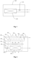
- Fig. 1 is a schematic diagram of the connection structure of a multi-split air conditioner indoor unit in the related art.
- the refrigerant circulation path of the multi-split air conditioner indoor unit 100 comprises a main liquid pipe, an electronic expansion valve 210, an indoor heat exchanger 220, and a main gas pipe (described with the refrigerant flow direction in the cooling mode as an example).
- a main liquid pipe a main liquid pipe
- an electronic expansion valve 210 a main electronic expansion valve
- an indoor heat exchanger 220 a main gas pipe
- a main gas pipe described with the refrigerant flow direction in the cooling mode as an example.
- the temperature of the refrigerant at different positions of the refrigerant circulation path and the environment temperature can further be obtained through the temperature sensors.
- the high-temperature and high-pressure refrigerant output from the outdoor unit directly flows into the indoor unit 100 through the main liquid pipe, and then is throttled through the electronic expansion valve 210 to become the low-temperature and low-pressure two-phase refrigerant, which has evaporation heat exchange in the indoor heat exchanger, and after heat exchange with indoor air, the cooled air is sent to the indoor.
- this disclosure provides a new form of multi-split air conditioner to improve the throttle sound with structural improvement and control strategy.
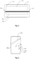
- Fig. 2 is a connection schematic diagram of an indoor unit of a multi-split air conditioner provided by the embodiment of the present disclosure.
- Fig. 3 is a connection schematic diagram of an indoor unit of a multi-split air conditioner provided by the embodiment of the present disclosure.
- Fig. 4 is a cross-sectional view of the indoor unit shown in Fig. 3 .
- the embodiment of the present disclosure provides a multi-split air conditioner comprising an outdoor unit and an indoor unit group, the indoor unit group comprising a plurality of indoor units 100 connected in parallel.
- At least one indoor unit 100 of the multi-split air conditioner comprises:
- a multi-split air conditioner comprises one or more outdoor units and a plurality of indoor units.
- a plurality of indoor units are disposed in parallel and connected to the outdoor unit through corresponding pipes, thereby realizing the flow of refrigerant.
- one of the indoor units in a multi-split air conditioner is taken as an example to explain the disclosure.
- the structure diagram of the outdoor unit is not shown.
- One skilled in the art can realize the connection between the indoor unit and the outdoor unit for the indoor unit provided by the embodiment, thereby forming the refrigerant circulation path of the multi-split air conditioner.
- the multi-split air conditioner may comprise one or more indoor units of the present embodiment.
- part or all of the refrigerant flow in the main flow path of the indoor unit enters the refrigerant inlet end of the electronic expansion valve after passing through the subcooling branch by the switching connection assembly, thereby improving the subcooling degree before the electronic expansion valve, making the refrigerant in the throttling process more stable, and achieving the purpose of improving the abnormal throttling sound on the indoor side of the multi-split air conditioner.
- the indoor heat exchanger 220 has an air inlet side and an air outlet side.
- the subcooler 310 is provided in a wind area on the outlet side of the indoor heat exchanger 220.
- the subcooler 310 may be a regenerator or a heat exchanger, such as a heat exchanger in the form of a single row of finned tubes with large fin spacing. Then, as the subcooler is mounted on the air outlet side of the indoor heat exchanger, the structural design will not increase the air resistance and has little influence on the air outlet of normal air conditioning of the air conditioner.
- the indoor unit 100 further comprises a main air duct 240 and a subcooling air duct 320.
- the main air duct 240 is provided with an indoor heat exchanger 220.
- the subcooling air duct 320 is disposed in a downstream air path of the main air duct 240 and connected in parallel with the main air duct 240, and the subcooler 310 is disposed in the subcooling air duct 320.
- the air inlet of the subcooling air duct 320 is further provided with a damper 330 configured to control the opening degree to change the air flow rate flowing through the main air duct 240 to the subcooling air duct 320.
- the airflow in the subcooling air duct is part of the airflow led out from the main air duct under the action of the damper.
- the air outlet of the subcooling air duct is connected to the main air duct, that is, the airflow of the subcooling air duct is discharged from the indoor unit through the main air duct after heat exchange with the subcooler.
- the opening degree of the damper can be adjusted according to the subcooling degree of the refrigerant output by the subcooler, so as to ensure the constant subcooling degree of the refrigerant before the valve, make the throttling process more stable and improve the throttling sound.
- the indoor unit 100 comprises an air inlet 110 and an air outlet 120.
- the indoor air enters the main air duct 240 from the air inlet 110 to exchange heat with the indoor heat exchanger 220.
- the cooled air after heat exchange enters the room through the air outlet 120.
- the damper 330 can rotate between position A and position B in the subcooling air duct 320.
- the damper 330 is at position A
- the subcooling air duct 320 is not connected to the main air duct 240, and air cannot enter the subcooling air duct 320.
- the damper 330 is at position B
- the air flow rate from the main air duct 240 to the subcooling air duct 320 is the maximum. Therefore, by adjusting the opening degree of the damper 330, it is possible to change the air flow rate from the main air duct 240 to the subcooling air duct 320.
- the direction in which the opening degree of the damper 330 is adjusted from the position A to the position B is defined as an adjustment direction of opening degree for increasing the air flow rate
- the direction from the position B to the position A is defined as an adjustment direction of opening degree for decreasing the air flow rate
- the switching connection assembly comprises: a first solenoid valve 410 disposed on the subcooling parallel section 230 and a second solenoid valve 420 disposed on the subcooling branch 300.
- the first solenoid valve 410 is controlled to turn on to make the subcooling parallel section 230 be connected to the electronic expansion valve 210
- the second solenoid valve 420 is controlled to turn on to make the subcooling branch 300 to be connected to the electronic expansion valve 210.
- the switching connection assembly can further be a three-way valve.
- the three-way valve is disposed at the inlet end of the subcooling branch 300 in parallel with the subcooling parallel section 230, the inlet end of which is connected to the main flow path 200, the first outlet end of which is connected to the subcooling parallel section 230, and the second outlet end of which is connected to the subcooling branch 300.
- the inlet end and the first outlet end are controlled to communicate to make the subcooling parallel section 230 to be connected to the electronic expansion valve 210
- the inlet end and the second outlet end are controlled to communicate to make the subcooling branch 300 to be connected to the electronic expansion valve 210.
- the switching connection device is switched to make the subcooling parallel section 230 connected to the electronic expansion valve 210 and the subcooling branch 300 is disconnected from the electronic expansion valve 210, that is the first solenoid valve 410 is turned on and the second solenoid valve 420 is turned off
- the refrigerant input from the outdoor unit enters the electronic expansion valve 210 from the subcooling parallel section 230 for throttling.
- the refrigerant enters the indoor heat exchanger 220 for evaporation heat exchange, and after heat exchange with indoor air, the refrigerant flows out of the indoor unit 100.
- the switching connection device is switched to make the subcooling parallel section 230 disconnected from the electronic expansion valve 210 and the subcooling branch 300 connected to the electronic expansion valve 210, that is the first solenoid valve 410 is turned off and the second solenoid valve 420 is turned on
- the refrigerant input from the outdoor unit enters through the main flow path 200 and is input into the subcooling branch path 300.
- the refrigerant is subcooled in the subcooling branch path 300, and the refrigerant with the increased subcooling degree enters the electronic expansion valve 210 for throttling.
- the refrigerant enters the indoor heat exchanger 220 for evaporation heat exchange, and after heat exchange with indoor air, the refrigerant flows out of the indoor unit 100.
- the communication device is switched to make the subcooling parallel section 230 connected to the electronic expansion valve 210 and the subcooling branch 300 connected to the electronic expansion valve 210, that is the first solenoid valve 410 is turned on and the second solenoid valve 420 is turned on, after passing through the main flow path 200, a part of the refrigerant input from the outdoor unit enters the subcooling parallel section 230 and the other part enters the subcooling branch path 300 for subcooling adjustment. After that, the two parts of refrigerant are jointly input into the electronic expansion valve 210 for throttling. After throttling, the refrigerant enters the indoor heat exchanger 220 for evaporation heat exchange, and after heat exchange with indoor air, the refrigerant flows out of the indoor unit 100.
- part or all of the refrigerant flow in the main flow path of the indoor unit enters the refrigerant inlet end of the electronic expansion valve after passing through the subcooling branch by the switching connection assembly, thereby improving the subcooling degree before the electronic expansion valve, making the refrigerant in the throttling process more stable, and achieving the purpose of improving the abnormal throttling sound on the indoor side of the multi-split air conditioner.
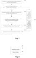
- Fig. 5 is a flow chart of a method for controlling the multi-split air conditioner provided by an embodiment of the present disclosure, which is adapted to the multi-split air conditioner shown in Fig. 2 .
- the method can be executed by a processor of the multi-split air conditioner or in a cloud server communicated with the multi-split air conditioner. It can further be executed at the control terminal of the multi-split air conditioner.
- the disclosure is explained by taking the processor of the multi-split air conditioner as the executive subject.
- the method for controlling the multi-split air conditioner comprises: S501, in response to a cooling mode operation command, obtaining a current first subcooling degree at the refrigerant inlet end of the electronic expansion valve.
- the current first subcooling degree refers to the subcooling degree before the electronic expansion valve at the current time, in a case where the refrigerant enters the electronic expansion valve through the subcooling parallel section.
- the subcooling parallel section of the indoor unit is connected to the electronic expansion valve, the subcooling branch is disconnected from the electronic expansion valve, and the refrigerant enters the electronic expansion valve from the main flow path through the subcooling parallel section for throttling. That is, the first solenoid valve is turned on and the second solenoid valve is turned off.
- the first preset subcooling degree n 1 is employed to indicate that the current subcooling degree is small, and there will be noise problems when the refrigerant flows through the electronic expansion valve, so the subcooling degree needs to be increased.
- the current first subcooling degree SC j1 is less than or equal to n 1 , which shows that the subcooling degree before the valve of the electronic expansion valve is low, and abnormal throttling sounds may occur. Therefore, by connecting the subcooling branch with the electronic expansion valve, part or all refrigerant enters the electronic expansion valve after passing through the subcooling branch for throttling. Because the subcooling branch improves the subcooling degree of the part or all refrigerant, the subcooling degree before the electronic expansion valve is adjusted, thus improving the abnormal throttling sound problem.
- controlling the switching connection assembly to connect the subcooling branch to the electronic expansion valve can comprise two situations. Only the subcooling branch connected to the electronic expansion valve, and the subcooling parallel section disconnected from the electronic expansion valve, all refrigerant enters the electronic expansion valve after passing through the subcooling branch. Or, the subcooling branch and the subcooling parallel section are both connected to the electronic expansion valve, a part of the refrigerant enters the subcooling parallel section and a part of the refrigerant enters the subcooling branch to adjust the subcooling degree, and after that, two parts of refrigerant are jointly input into the electronic expansion valve for throttling.
- the connecting state of the switching connection assembly is controlled.
- the connecting state of the switching connection assembly is controlled to be that only the subcooling branch is connected to the electronic expansion valve, and the subcooling parallel section is disconnected from the electronic expansion valve, so as to greatly improve the subcooling degree of the refrigerant.
- the connecting state of the switching connection assembly is controlled to be that the subcooling branch and the subcooling parallel section are both connected to the electronic expansion valve, so that the problem of abnormal throttling sound is improved by adjusting the subcooling degree of part of refrigerant.
- the proportion of the refrigerant entering the subcooling branch and the subcooling parallel section can be adjusted according to the proportion adjustment range where the absolute value of the difference between SC j1 and n 1 is located.
- the corresponding relationship between the absolute value of the difference between SC j1 and n 1 and the refrigerant proportion adjustment range can be obtained by experiments.
- the current proportional adjustment range corresponding to the absolute value of the current difference value can be obtained by inquiring the database, so as to adjust the proportion of refrigerant entering the subcooling branch and the subcooling parallel section according to the current proportional adjustment range.
- the proportion of refrigerant entering the subcooling branch and the subcooling parallel section can be adjusted by adjusting the opening degree of the switching connection device.
- the step of obtaining the current subcooling degree at the refrigerant inlet end of the electronic expansion valve comprises: according to a difference between a current condensation temperature of the outdoor unit and a first refrigerant temperature at the refrigerant inlet end of the electronic expansion valve, determining the current first subcooling degree.
- the current condensation temperature can be converted from the current refrigerant pressure at the outlet of the condenser of the outdoor unit, according to the corresponding relationship between temperature and saturation pressure, thus obtaining the current condensation temperature TC of the outdoor unit.
- the subcooling degree may be reduced by the flow of refrigerant in the pipes due to the resistance loss and heat loss of the pipeline extension, so it is necessary to correct the current refrigerant pressure via the subcooling correction parameter.
- Fig. 6 is a flow chart of the method for controlling the multi-split air conditioner provided by the embodiment of the present disclosure, which is adapted to the multi-split air conditioner shown in Fig. 2 , and the indoor unit comprises a main air duct and a subcooling air duct.
- the method can be executed by a processor of the multi-split air conditioner or in a cloud server communicated with the multi-split air conditioner. It can further be executed at the control terminal of the multi-split air conditioner.
- the disclosure is explained by taking the processor of the multi-split air conditioner as the executive subject.
- the method for controlling the multi-split air conditioner comprises:
- the air flow from the subcooling air duct exchanges heat with the subcooler, thus increasing the subcooling degree of the refrigerant in the subcooler.
- the second refrigerant temperature can be the refrigerant temperature at the outlet end of the subcooler of the subcooling branch or the refrigerant temperature at the outlet end of the pipeline of the subcooling branch.
- the current second subcooling degree refers to the subcooling degree before the electronic expansion valve at the current time, in a case where part or all the refrigerant enters the electronic expansion valve after passing through the subcooling branch.
- SC j2 is the current second subcooling degree
- TC is the current condensation temperature
- T 1,j2 is the second refrigerant temperature
- k is a subcooling correction parameter
- the step of, according to the preset subcooling degree range where the current second subcooling degree is located, controlling the air flow rate from the main air duct to the subcooling air duct comprises:
- the air flow rate from the main air duct to the subcooling air duct is adjusted, so that the second subcooling degree is kept in an appropriate range, and no obvious throttling sound will occur during throttling.
- the second preset subcooling degree n 2 is employed to indicate that the current subcooling degree is large, and there will be noise problems when the refrigerant flows through the electronic expansion valve, so it is necessary to reduce the subcooling degree.
- the second subcooling degree is maintained within the range of (n 1 , n 2 ] (i.e., the appropriate subcooling degree range), the purpose of improving the abnormal throttling sound has been achieved.
- the values of the appropriate subcooling degree range are determined according to the environment temperature parameters and/or the caliber parameters of the electronic expansion valve.
- the environment temperature parameters comprise the outdoor environment temperature and the indoor environment temperature.
- the larger the caliber parameter of the electronic expansion valve the smaller the values of the lower and upper limits of the appropriate subcooling degree range.
- the corresponding relationship between environment temperature parameters, electronic expansion valve caliber parameters, and appropriate subcooling degree range can be obtained by means of experiments.
- the current appropriate subcooling degree range corresponding to the current environment temperature parameter and/or the caliber parameter of the electronic expansion valve can be obtained by inquiring the database, thereby controlling the air flow from the main air duct to the subcooling air duct according to the numerical relationship between the current second subcooling degree and the current appropriate subcooling degree range.
- the method further comprises: according to a preset duration, obtaining the second refrigerant temperature and the condensation temperature at the outlet end of the subcooling branch at intervals.
- the preset duration is defined as an adjustment duration to adjust the air flow rate entering the subcooling air duct at intervals in a case where the main air duct is connected to the subcooling air duct, so that the subcooling degree before the valve determined according to the second refrigerant temperature and the condensation temperature is maintained within the appropriate subcooling degree range.
- the air flow rate from the main air duct to the subcooling air duct is adjusted by adjusting the opening degree of the damper provided on the subcooling air duct.
- the step of controlling the air flow rate from the main air duct to the subcooling air duct to increase can comprise: controlling the stepper motor to drive the damper to rotate in the direction of increasing the opening degree.
- step of controlling the stepper motor to drive the damper to rotate in the direction of increasing the opening degree can comprise:
- the step of controlling the stepper motor to drive the damper to rotate in the direction of decreasing the opening degree can comprise:
- the damper rotation value can be controlled in real-time according to SC j2 , and the air flow rate entering the subcooling air duct can be reduced, thereby avoiding the occurrence of excessive subcooling.
- Fig. 7 is a flow chart of a method for controlling the multi-split air conditioner provided by an embodiment of the present disclosure, which is adapted to the multi-split air conditioner shown in Fig. 2 .
- the method can be executed by a processor of the multi-split air conditioner or in a cloud server communicated with the multi-split air conditioner. It can further be executed at the control terminal of the multi-split air conditioner.
- the disclosure is explained by taking the processor of the multi-split air conditioner as the executive body.
- the method for controlling the multi-split air conditioner comprises:
- the outdoor environment temperature is greater than the preset temperature, which indicates that the outdoor environment temperature is high, which may affect the refrigerant temperature of the pipes from the outdoor unit to the indoor unit, resulting in insufficient subcooling before the valve.
- the preset temperature can be 26°C-30°C, for example, 26°C, 27°C, 28°C, 29°C and 30°C. In the embodiment, the preset temperature is set to 27°C.
- the operation of obtaining the subcooling degree before the valve is triggered, and then the values of the current first subcooling degree at the refrigerant inlet end of the electronic expansion valve and the first preset subcooling degree is employed to determine whether it is necessary to increase the subcooling degree before the valve by connecting the subcooling branch, so as to achieve the purpose of improving the abnormal noise of throttling sound.
- the outdoor environment temperature is less than or equal to the preset temperature, which indicates that the outdoor environment temperature has little influence on the refrigerant temperature of the pipes from the outdoor unit to the indoor unit, and the possibility of insufficient subcooling before the valve is reduced.
- the connection relationship between the subcooling branch and the electronic expansion valve is disconnected, so that the refrigerant directly enters the electronic expansion valve through the main flow path.
- the switching connection assembly is controlled and switched to realize that part or all the refrigerant flow in the main flow path of the indoor unit enters the refrigerant inlet end of the electronic expansion valve after passing through the subcooling branch, so as to improve the subcooling degree before the electronic expansion valve and further make the refrigerant in the throttling process more stable.
- the refrigerant circulation of the main flow path is restored.
- Fig. 8 is a schematic diagram of a device for controlling the multi-split air conditioner provided by the embodiment of the present disclosure.
- the device for controlling the multi-split air conditioner can be realized by software, hardware, or a combination of the two.
- the device 80 for controlling a multi-split air conditioner comprises an acquisition module 81 and a control module 82, where the acquisition module 81 configured to, in response to a cooling mode operation command, obtain a current first subcooling degree at a refrigerant inlet end of an electronic expansion valve; and the control module 82 configured to, in a case where the current first subcooling degree is less than or equal to a first preset subcooling degree, control a switching connection assembly to connect a subcooling branch with the electronic expansion valve.
- Fig. 9 is a schematic diagram of a device for controlling the multi-split air conditioner provided by the embodiment of the present disclosure.
- the device 90 for controlling the multi-split air conditioner comprises: a processor 90 and a memory 91.
- the device can further comprise a communication interface 92 and a bus 93.
- the processor 90, the communication interface 92, and the memory 91 can communicate with each other via the bus 93.
- the communication interface 92 may be used for information transmission.
- the processor 90 may invoke logic instructions in memory 91 to execute the method for controlling the multi-split air conditioner of the above embodiments.
- logic instructions in the memory 91 described above may be realized in the form of software functional units and may be stored in a computer-readable storage medium when sold or used as a separate product.
- the memory 91 as a computer-readable storage medium may be used to store software programs and computer-executable programs such as program instructions/modules corresponding to the methods in embodiments of the present disclosure.
- the processor 90 executes functional disclosures as well as data processing by running program instructions/modules stored in the memory 91 that is to implement the method for controlling the multi-split air conditioner in the above-described embodiments.
- the memory 91 may comprise a stored program area and a stored data area wherein the stored program area may store an operating system or a disclosure program required for at least one function.
- the storage data area may store data created according to the use of the terminal device.
- the memory 91 may comprise a high-speed random access memory and can further comprise a non-volatile memory.
- the embodiments of the present disclosure provide a multi-split air conditioner comprising the device 80(90) for controlling the multi-split air conditioner described above.
- the embodiments of the present disclosure provide a computer-readable storage medium storing computer-executable instructions configured to execute the method for controlling the multi-split air conditioner.
- the embodiments of the present disclosure provide a computer program that, when executed by a computer, causes the computer to implement the method for controlling a multi-split air conditioner.
- the embodiments of the present disclosure provide a computer program product comprising a computer program stored on a computer-readable storage medium, the computer program comprising program instructions that, when executed by a computer, cause the computer to execute the above-described method for controlling the multi-split air conditioner.
- the computer-readable storage medium may be a transitory computer-readable storage medium or a non-transitory computer-readable storage medium.
- the technical solution of the disclosed embodiments may be embodied in the form of a software product stored in a storage medium, comprising one or more instructions for causing a computer device (which may be a personal computer, server, or network device, etc.) to perform all or part of the steps of the method of the disclosed embodiments.
- the aforementioned storage medium may be a non-transient storage medium, comprising a USB disk, a mobile hard disk, a Read-Only Memory (ROM), a Random Access Memory (RAM), a magnetic disk or an optical disk, and other media capable of storing program codes, or may be a transient storage medium.
- the term “comprise” and its variants “comprises” and/or “comprising”, etc. refer to the presence of stated features, totals, steps, operations, elements, and/or components, but do not exclude the presence or addition of one or more other features, totals, steps, operations, elements, components, and/or groupings of these.
- an element defined by the phrase “comprises a/an " does not preclude the existence of another identical element in the process, method or apparatus in which the element is comprised.
- each embodiment may be highlighted as being different from the other embodiments and the same similar parts between the various embodiments may be referred to with respect to each other.
- the method, product, etc. disclosed by the embodiment if it corresponds to the method portion disclosed by the embodiment, reference can be made to the description of the method portion where relevant.
- the disclosed methods, products may be implemented in other ways.
- the above-described embodiment of the apparatus is only schematic, for example, the division of the unit may be only a logical function division, and in practice there may be another division mode, for example, multiple units or components may be combined or integrated into another system, or some features may be ignored or not performed.
- the coupling or direct coupling or communication connection between each other shown or discussed may be indirect coupling or communication connection through some interface, device or unit, and may be electrical, mechanical or other form.
- the elements illustrated as separate elements may or can not be physically separated, and the elements displayed as elements may or can not be physical elements, i.e.
- each functional unit in the embodiment of the present disclosure may be integrated in one processing unit, each unit may exist physically alone, or two or more units may be integrated in one unit.
- each block in a flow chart or block diagram may represent a module, program segment, or part of code containing one or more executable instructions for performing a specified logical function.
- the functions indicated in the boxes may further occur in a different order than those indicated in the drawings. For example, two successive boxes can actually be executed substantially in parallel, or they can sometimes be executed in reverse order, depending on the functionality involved.
- each block in the block diagram and/or flow chart, and a combination of the blocks in the block diagram and/or flow chart may be implemented in a dedicated hardware-based system that performs a specified function or action, or may be implemented in a combination of dedicated hardware and computer instructions.
Landscapes
- Engineering & Computer Science (AREA)
- Mechanical Engineering (AREA)
- General Engineering & Computer Science (AREA)
- Chemical & Material Sciences (AREA)
- Combustion & Propulsion (AREA)
- Physics & Mathematics (AREA)
- Thermal Sciences (AREA)
- Signal Processing (AREA)
- Fuzzy Systems (AREA)
- Mathematical Physics (AREA)
- Air Conditioning Control Device (AREA)
- Compression-Type Refrigeration Machines With Reversible Cycles (AREA)
Applications Claiming Priority (2)
| Application Number | Priority Date | Filing Date | Title |
|---|---|---|---|
| CN202210445855.XA CN116989450A (zh) | 2022-04-26 | 2022-04-26 | 多联机空调、用于控制多联机空调的方法及装置 |
| PCT/CN2022/132550 WO2023207040A1 (zh) | 2022-04-26 | 2022-11-17 | 多联机空调、用于控制多联机空调的方法及装置 |
Publications (2)
| Publication Number | Publication Date |
|---|---|
| EP4407248A1 true EP4407248A1 (de) | 2024-07-31 |
| EP4407248A4 EP4407248A4 (de) | 2025-04-02 |
Family
ID=88517176
Family Applications (1)
| Application Number | Title | Priority Date | Filing Date |
|---|---|---|---|
| EP22939855.7A Pending EP4407248A4 (de) | 2022-04-26 | 2022-11-17 | Multisplit-klimaanlage sowie verfahren und vorrichtung zur steuerung davon |
Country Status (4)
| Country | Link |
|---|---|
| US (1) | US20240337407A1 (de) |
| EP (1) | EP4407248A4 (de) |
| CN (1) | CN116989450A (de) |
| WO (1) | WO2023207040A1 (de) |
Families Citing this family (1)
| Publication number | Priority date | Publication date | Assignee | Title |
|---|---|---|---|---|
| CN119222855B (zh) * | 2024-11-06 | 2026-01-30 | 珠海格力电器股份有限公司 | 空调系统及其控制方法、装置、存储介质和程序产品 |
Family Cites Families (13)
| Publication number | Priority date | Publication date | Assignee | Title |
|---|---|---|---|---|
| KR100618212B1 (ko) * | 2003-10-16 | 2006-09-01 | 엘지전자 주식회사 | 에어컨의 냉매 온도 제어 시스템 및 그 제어방법 |
| KR100539570B1 (ko) * | 2004-01-27 | 2005-12-29 | 엘지전자 주식회사 | 멀티공기조화기 |
| CN102003773A (zh) * | 2010-11-25 | 2011-04-06 | 佛山市中格威电子有限公司 | 变频空调器多联机的分流补偿控制系统 |
| KR101232579B1 (ko) * | 2011-01-20 | 2013-02-12 | 엘지전자 주식회사 | 멀티형 공기조화기 |
| CN102734865B (zh) * | 2011-04-12 | 2015-05-13 | 珠海格力电器股份有限公司 | 多联机空调系统及其控制方法 |
| CN102635926B (zh) * | 2012-04-26 | 2018-08-24 | 青岛海尔空调电子有限公司 | 空调系统和用于空调系统的压力调整方法 |
| CA2904734C (en) * | 2013-03-15 | 2018-01-02 | Emerson Electric Co. | Hvac system remote monitoring and diagnosis |
| CN110375466B (zh) * | 2018-04-13 | 2022-10-28 | 开利公司 | 用于空气源热泵系统的制冷剂泄露的检测装置和方法 |
| CN111023272A (zh) * | 2019-12-30 | 2020-04-17 | 宁波奥克斯电气股份有限公司 | 多联机空调系统的控制方法、装置和多联机空调系统 |
| CN111397239B (zh) * | 2020-03-13 | 2021-12-10 | 海信(山东)空调有限公司 | 多联机空调系统及降低多联机空调系统噪音的方法 |
| CN111845821A (zh) * | 2020-07-29 | 2020-10-30 | 山东朗进科技股份有限公司 | 一种空调及一种除湿方法 |
| CN112833473A (zh) * | 2021-01-08 | 2021-05-25 | 北京工业大学 | 一种模块式室内自然对流换热单元的热泵系统 |
| CN215295159U (zh) * | 2021-06-04 | 2021-12-24 | 山东朗进科技股份有限公司 | 一种除湿精密空调系统 |
-
2022
- 2022-04-26 CN CN202210445855.XA patent/CN116989450A/zh active Pending
- 2022-11-17 WO PCT/CN2022/132550 patent/WO2023207040A1/zh not_active Ceased
- 2022-11-17 US US18/700,026 patent/US20240337407A1/en active Pending
- 2022-11-17 EP EP22939855.7A patent/EP4407248A4/de active Pending
Also Published As
| Publication number | Publication date |
|---|---|
| WO2023207040A1 (zh) | 2023-11-02 |
| EP4407248A4 (de) | 2025-04-02 |
| CN116989450A (zh) | 2023-11-03 |
| US20240337407A1 (en) | 2024-10-10 |
Similar Documents
| Publication | Publication Date | Title |
|---|---|---|
| AU2022271465B2 (en) | Air conditioning unit, and operation control method and operation control device for air conditioning unit | |
| US11320185B2 (en) | Defrosting control method for multi-split system | |
| US10612799B2 (en) | Multi-split system and medium-pressure controlling method thereof | |
| US7325414B2 (en) | Hybrid tandem compressor system with economizer circuit and reheat function for multi-level cooling | |
| EP2837898B1 (de) | Klimatisierungssystem | |
| AU2011357097B2 (en) | Air-conditioning apparatus | |
| US20090320506A1 (en) | Refrigerant system with expansion device bypass | |
| CN110030757A (zh) | 多联机空调及其控制方法 | |
| US6817205B1 (en) | Dual reversing valves for economized heat pump | |
| CN111520869B (zh) | 一种多联机系统的室内机冷媒精确分配控制方法 | |
| EP4407248A1 (de) | Multisplit-klimaanlage sowie verfahren und vorrichtung zur steuerung davon | |
| EP4083522B1 (de) | Paralleles nichtumkehrbares abtausystem mit mehreren ausseneiheiten und abtausteuerverfahren davon | |
| JPS59131863A (ja) | 空気調和装置 | |
| WO2021120784A1 (zh) | 多联机空调系统 | |
| EP3855094A1 (de) | Kühl- und heizumschaltvorrichtung für variables kältemittelstromsystem mit wärmerückgewinnung, variables kältemittelstromsystem und steuerverfahren | |
| US7228708B2 (en) | Multi-temp system with tandem compressors and reheat function | |
| CN111219784B (zh) | 室内机冷媒控制装置及其控制方法、室内机和空调系统 | |
| CN213421283U (zh) | 一种可控制多个室外机换热器的多联式空调室外机 | |
| CN114659305A (zh) | 空调冷媒循环的控制方法、控制系统、电子设备和介质 | |
| CN115264793B (zh) | 用于控制空调节能的方法、装置、空调和存储介质 | |
| US20210262690A1 (en) | Multi-Split Air Conditioner and Control Method Thereof | |
| CN210154123U (zh) | 空调系统 | |
| CN116182322B (zh) | 用于空调器防液击的方法、装置、空调器及存储介质 | |
| JPS6146347Y2 (de) | ||
| CN118816373B (zh) | 用于换热系统的控制方法、控制装置和换热系统 |
Legal Events
| Date | Code | Title | Description |
|---|---|---|---|
| STAA | Information on the status of an ep patent application or granted ep patent |
Free format text: STATUS: THE INTERNATIONAL PUBLICATION HAS BEEN MADE |
|
| PUAI | Public reference made under article 153(3) epc to a published international application that has entered the european phase |
Free format text: ORIGINAL CODE: 0009012 |
|
| STAA | Information on the status of an ep patent application or granted ep patent |
Free format text: STATUS: REQUEST FOR EXAMINATION WAS MADE |
|
| 17P | Request for examination filed |
Effective date: 20240422 |
|
| AK | Designated contracting states |
Kind code of ref document: A1 Designated state(s): AL AT BE BG CH CY CZ DE DK EE ES FI FR GB GR HR HU IE IS IT LI LT LU LV MC ME MK MT NL NO PL PT RO RS SE SI SK SM TR |
|
| A4 | Supplementary search report drawn up and despatched |
Effective date: 20250304 |
|
| RIC1 | Information provided on ipc code assigned before grant |
Ipc: F24F 1/0068 20190101ALI20250226BHEP Ipc: F25B 41/42 20210101ALI20250226BHEP Ipc: F24F 11/84 20180101AFI20250226BHEP |
|
| DAV | Request for validation of the european patent (deleted) | ||
| DAX | Request for extension of the european patent (deleted) |