EP4407124A1 - Türschloss - Google Patents
Türschloss Download PDFInfo
- Publication number
- EP4407124A1 EP4407124A1 EP23216924.3A EP23216924A EP4407124A1 EP 4407124 A1 EP4407124 A1 EP 4407124A1 EP 23216924 A EP23216924 A EP 23216924A EP 4407124 A1 EP4407124 A1 EP 4407124A1
- Authority
- EP
- European Patent Office
- Prior art keywords
- door
- lock
- break
- rotation
- attempt
- Prior art date
- Legal status (The legal status is an assumption and is not a legal conclusion. Google has not performed a legal analysis and makes no representation as to the accuracy of the status listed.)
- Granted
Links
Images


Classifications
-
- E—FIXED CONSTRUCTIONS
- E05—LOCKS; KEYS; WINDOW OR DOOR FITTINGS; SAFES
- E05B—LOCKS; ACCESSORIES THEREFOR; HANDCUFFS
- E05B45/00—Alarm locks
-
- E—FIXED CONSTRUCTIONS
- E05—LOCKS; KEYS; WINDOW OR DOOR FITTINGS; SAFES
- E05B—LOCKS; ACCESSORIES THEREFOR; HANDCUFFS
- E05B15/00—Other details of locks; Parts for engagement by bolts of fastening devices
- E05B15/16—Use of special materials for parts of locks
- E05B15/1614—Use of special materials for parts of locks of hard materials, to prevent drilling
- E05B2015/1628—Free-rotating protecting covers or discs
Definitions
- the invention relates to a door lock and a method for detecting a break-in attempt using this lock.
- a door lock is known to demand DE3913204A1 .
- This lock has an anti-drilling pad present in front of the entrance to the key channel of the lock cylinder rotor.
- this lock is robust against break-in attempts by drilling the cylinder rotor.
- this lock is advantageous in that it includes a device for detecting a break-in attempt capable of detecting a break-in attempt by drilling the rotor of the cylinder.
- the burglary detection device includes conductive tracks which are damaged when the rotor is drilled. It is the damage to these conductive tracks which triggers the report of a break-in attempt.
- Such a burglary detection device is reliable in the sense that there are very few false positives.
- the invention aims to remedy this drawback by proposing a lock equipped with a break-in attempt detection device which has the same advantages while allowing faster detection of a break-in attempt by drilling the rotor of the cylinder .
- the lock 8 is described in the particular case where it is a door strip. Consequently, the numerical reference 8 is also used to designate the door strip.
- Door 4 is located at the entrance to the home. This door 4 demarcates the interior of the home from the exterior of the home. Subsequently, the terms “interior” and “exterior” are used to designate what is located, respectively, inside and outside the home.
- door 4 is a landing door to an apartment or a house or any other accommodation.
- Door 4 has an interior face facing the interior of the home and, on the opposite side, an exterior face. The interior and exterior faces extend primarily in parallel vertical planes.
- the door 4 can be moved between an open position, shown on the figure 1 , and a closed position. In the open position, a person can enter the home and therefore move from outside the home to the interior. Conversely, in the closed position, a person cannot enter the home.
- Terminal 6 is for example located outside the home and can be several kilometers from the home. To simplify the figure 1 , only one terminal 6 is represented. However, in practice, there are often several copies of Terminal 6 that work the same way. Only terminal 6 is described in more detail below.
- the interface 20 includes, for example, one or more buttons operable by the owner. Here, it notably includes a button 26 to trigger the sending of the unlocking command.
- the transceiver 22 makes it possible to connect the terminal 6 to the strip 8 via a long-distance telecommunications network 28 such as a wireless telephone network or the Internet network.
- Terminal 6 is, for example, the owner's smartphone.
- Strip 8 is a multi-point door strip.
- the strip 8 is mounted, without any degree of freedom, on the interior face of the door 4.
- the headband 8 is in the form of a single piece inside which the different components described with reference to the figure 2 .
- the strip 8 is in the form of a rigid housing 30 inside which its various components are fixed.
- the housing 30 is here fixed along the vertical edge of the door 4 located on the side opposite the hinges.
- the housing 30 is fixed to the interior face of the door 4, for example, using screws.
- the strip 8 can be installed on the interior face of a pre-existing door.
- the bolt 36 can be moved by the handle 38 from an extended position (shown on the figure 1 ) to a retracted position.
- the bolt 36 is pushed back, permanently, towards an extended position by a return spring.
- the distal end of the bolt 36 is beveled so that when the door 4 is slammed from its open position to its closed position, by cooperation in shape between the beveled end and an upright 40, the bolt 36 sinks into the interior of the housing 30 against the force of the return spring in order to allow the door 4 to reach its closed position.
- the amount 40 is fixed, without any degree of freedom, on the frame of the door 4.
- Each of the deadbolts 42 can be moved between an extended position and a retracted position. In the extended position, each bolt 42 is received in a corresponding cavity provided in the upright 40 to lock the door 4 in its closed position. In its retracted position, each bolt 42 is retracted inside the housing 30 and located outside the cavity provided in the upright 40. Thus, when all the bolts 42 are in their retracted position, the door 4 is unlocked and can freely be moved from its closed position to its open position after having pressed the handle 38.
- the strip has at least five bolts 42.
- each bolt 42 is a cylindrical bar movable in translation between its extended and retracted positions. Unlike bolt 36, the distal ends of bolts 42 are not beveled.
- the touch screen 44, the lock cylinder 46 and the reading head 48 are accessible by a person located inside the home.
- FIG. 1 also represents an orthogonal coordinate system XYZ.
- the Z direction of this mark corresponds to the vertical.
- the X and Y directions are horizontal.
- the direction X is parallel to the vertical plane in which the door 4 mainly extends when it is in its closed position.
- the direction X is directed from the edge of the door along which the strip 8 is fixed, towards the hinges of this door.
- the Y direction is directed from inside the home to outside the home. Terms such as “forward” and “backward” are defined relative to the Y direction.
- FIG. 1 schematically represents the interior architecture of the strip 8 as well as different elements connected to this strip 8.
- the strip 8 comprises, mainly housed inside the housing 30, a bolt mechanism 50 and a system 52 for actuating the mechanism 50.
- the mechanism 50 includes the bolts 42 as well as the linkage necessary to move them between their extended and retracted positions. On the other hand, in this embodiment, the mechanism 50 does not include the bolt 36.
- the actuation system 52 moves the mechanism 50 from a protruding state to a retracted state and vice versa.
- the protruding state at least one bolt 42 is in its extended position.
- the system 52 comprises a toothed wheel meshed with a rack of the bolt mechanism 50.
- this toothed wheel rotates, in a first direction, this moves the mechanism 50 from its protruding state to its state hidden away.
- this same toothed wheel turns in the opposite direction, this moves the mechanism 50 from the retracted state to its protruding state.
- the system 52 does not allow the bolt 36 to be moved.
- the bolt 36 can only be moved using the handle 38.
- the system 52 comprises an electric motor 60 and the cylinder 46.
- the cylinder 46 makes it possible in particular to move the mechanism 50 from its protruding state to its retracted state even in the event of unavailability of the electric motor 60.
- the motor 60 is said to be "unavailable” when it cannot be used to move the mechanism 50 from its salient state to its retracted state.
- Such unavailability may result from a breakdown of the motor 60 or another element of the actuation system 52. This unavailability can also result, for example, from a cut in the electrical power supply to the motor 60.
- the cylinder 46 is a mechanical cylinder devoid of any electronic component which requires power to operate.
- cylinder 46 is a mechanical cylinder in European format.
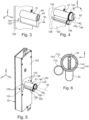
- it comprises an inner half-cylinder and an outer half-cylinder 61 ( Figure 3 ) accessible, respectively, from the interior and exterior sides of the door 4.
- the cylinder 46 can be used both from the exterior side of the door 4 and from its interior side.
- the strip 8 comprises a housing passing right through the housing 30 in the direction Y and into which the inner half-cylinder of the cylinder 46 is inserted. This housing is located opposite a hole passing through the door 4 in the Y direction and in which the outer half-cylinder 61 of the cylinder 46 is inserted.
- the cylinder 46 is only fixed, without any degree of freedom, to the door 4 using a screw whose screw head is only accessible from the vertical edge of the door 4 or the housing 30.
- the cylinder 46 comprises a rotor 62 rotatably mounted inside a fixed stator 64.
- the stator 64 is fixed, without any degree of freedom, to the door 4.
- the rotor 62 comprises a key channel 66 which opens from the interior side and exterior side. This channel 66 is intended to receive a key.
- the rotor 62 can be rotated around an axis 63 ( Figures 3 to 5 , 7 and 8 ) rotation only when a key authorized is introduced inside channel 66 then turned.
- An authorized key is a key authorized to move the mechanism 50 to its retracted state.
- rotor 62 is blocked from rotating and cannot rotate around its axis 63 of rotation.
- the cylinder 46 comprises a first set of pins movable in translation inside the stator 64 and, opposite, a second set of pins movable in translation inside the rotor 62 by the key inserted into channel 66.
- the pins of the first set are also known as "counter pins”.
- the interfaces between the pins of the first and second sets of pins are all located at the interface between the rotor 62 and the stator 64, which releases the rotation of the rotor 62.
- the interface between the rotor 62 and the stator 64 is also known as the "gap line".
- the interfaces between the pins of the first and second sets of pins are not all located at the interface between the rotor 62 and the stator 64, which prevents the rotation of the rotor 62.
- the cylinder 46 also includes a bit 68.
- the bit 68 is rotated by the rotor 62 when this rotor turns. It is the rotation of this bit 68 which activates the movement of the mechanism 50 towards its retracted state.
- the motor 60 includes a drive shaft 70.
- the motor 60 When the motor 60 is controlled to move the mechanism 50 to its retracted state, it is the rotation of the shaft 70 which activates the movement of the mechanism 50.
- the system 52 comprises an output shaft 72 and a mechanism 74 for mechanically coupling the bit 68 and the shaft 70 to this shaft 72 to cause it to rotate.
- the shaft 72 moves the mechanism 50 from its protruding state to its retracted state when it is turned in one direction and from its retracted state to its protruding state when it is turned in the opposite direction.
- the coupling mechanism 74 is identical to one of those described in the French patent application filed under number FR2203725 on 04/21/2022 by the company COGELEC.
- the transmitter/receiver 86 is able to establish a wireless communication link with the terminal 6 via the network 28.
- the badge reading head 48 is connected to the unit 80 to transmit to the module 92 of the unit 80 the access rights read in the memory of a badge 94.
- the badge 94 is a transportable badge, by hand , by a human being. If the access rights read in the badge 94 correspond to access rights authorized to unlock the strip 8, the module 92 controls the motor 60 to move the mechanism 50 into its retracted state. Otherwise, the mechanism 50 remains in the protruding state.
- the badge 94 is a transponder badge which transmits the access rights contained in its memory only when it is presented near the head 48.
- the strip 8 also includes an angular sensor 98 connected to the control unit 80 and housed inside the housing 30.
- the apparatus 96 includes a camera, a speaker and a microphone. This device 96 is, for example, mounted on the exterior face of door 4.
- the exterior head 100 is used to acquire the access rights of a person located on the exterior side of the door 4 and, in response, unlock the door 4 if the acquired access rights authorize this unlocking.
- the head 100 is capable of reading the access rights recorded in the same badges as those used with the head 48.
- the same badge 94 can be used both with the head 48 and with the head 100.
- the head 100 is structurally identical to the head 48 except that it is located on the exterior side of the door 4.
- the head 100 is mounted on the exterior face of the door 4.
- the unit 80 is also capable of controlling the motor 60 to rotate the shaft 70 in the opposite direction and thus return the mechanism 50 to its protruding state. For example, after a predetermined duration DF has elapsed since the door 4 was placed in its closed position, the unit 80 automatically controls the motor 60 to return the mechanism 50 to its protruding state. To know if the door 4 is in its closed position, the strip 8 includes a sensor 102 for opening/closing the door 4 connected to the control unit 80.
- the housing 30 of the headband 8 includes a rear plate 120 ( Figures 3 to 6 ) fixed, without any degree of freedom, on the interior face of the door 4.
- this rear plate is fixed using screws on the interior face of the door 4.
- this rear plate is made of metal .
- This plate 120 has an orifice 122 ( Figure 3 ) through which allows the half-cylinder 61 to project from the exterior side of the plate 120 while the interior half-cylinder is largely contained inside the housing 30.
- the cross section of this orifice 122 follows the perimeter of the half-cylinder 61.
- the strip 8 includes an anti-drilling pad 140 ( Figures 4 to 8 , 10 And 12 to 14 ).
- the pellet 140 is located in front of the exterior entrance of the key channel 66 and mounted freely in rotation around the axis 63. Thus, if the end of a drill bit from a drill is applied to the pellet 140, it this is driven in rotation around axis 63. Since the pellet 140 then rotates at the same speed as the drill bit, this makes drilling of the rotor 62 very difficult.
- the pellet 140 has a slot 142 located in front of the exterior entrance of the channel 66.
- the dimensions of the cross section of this slot 142 are large enough to allow the passage of the blade of the authorized key. Thus, the blade of an authorized key can pass through the slot 142 then be introduced into the channel 66.
- the dimensions of the cross section of the slot 142 are sufficiently small to prevent the passage of a drill bit of 6 mm or 8 mm in diameter.
- slot 142 is a rectangular slot whose width is less than 5 mm or 3 mm.
- the pellet 140 comprises a metal cylinder 144 ( Figures 4, 5 , 7, 8 ) of circular cross section and whose axis of revolution coincides with axis 63. Slot 142 passes right through this cylinder 144 to emerge opposite the entrance to channel 66.
- the axis of rotation of the pinion 152 coincides with the axis 63.
- the pinion 152 extends along the outer periphery of the cylinder 144 and makes a complete tour of the cylinder 144. It is fixed on the end of the cylinder 144 facing the interior side of the door 4.
- the pinion 152 forms only one block of material with the anti-drilling pad 140.
- the rod 126 transmits the rotational movement of the pellet 140 to the angular sensor 98.
- it extends parallel to the axis 63 from an interior end located near the sensor 98 to a outer end meshed with pinion 152.
- rod 126 also rotates at a speed which is proportional to the speed of rotation of pinion 152.
- the outer end of rod 126 comprises a pinion 154 ( Figures 4 to 8 ) whose teeth are directly engaged with the teeth of pinion 152.
- the inner end of the rod 126 includes a permanent magnet 156 ( Figure 8 ) fixed without any degree of freedom on this interior end.
- the inner end of the rod 126 has a housing 158 ( Figure 7 ) inside which the magnet 156 is fixed.
- the sensor 98 measures the angular position of the interior end of the rod 126. For this, here, it measures the angular position of the magnet 156.
- the sensor 98 is a magnetic field sensor which delivers to the unit 80 an electrical signal representative of the angular position of the magnet 156 around the axis of rotation of the rod 126. This electrical signal is also representative of the angular position of the pellet 140 around the axis 63.
- the combination of the unit 150 for measuring the rotation of the pellet 140 and the detection module 92 forms a device for detecting an attempted break-in capable, in particular, of detecting an attempted break-in by drilling the rotor 62 .
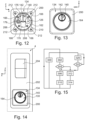
- Part 130 includes a barrel 160 ( Figures 7 to 9 ) which extends along the axis 63 from a rear face 162 ( Figures 7 to 9 , 12 ) up to a front face 164 ( Figures 7 to 9, 10 , 13 to 14 ).
- the faces 162 and 164 are flat and parallel to the rear plate 120.
- the rear face 162 is fixed, without any degree of freedom, on the plate 120 and directly mechanically supported on this plate 120.
- it has four tapped holes 166 ( Figures 7 and 9 ) which come opposite the holes 128 so as to allow the barrel 160 to be fixed on the plate 120 by four fixing screws.
- the barrel 160 has a blind bore 170 ( Figures 7, 9 , 12 ) to receive the lower part of the stator of the half-cylinder 61 and a stop 176 ( Figures 7 to 9 , 12 ).
- This bore 170 opens into the rear face 162.
- the stator of the half-cylinder 61 is slidably received inside the bore 170. More precisely, the exterior portion of the stator 64 of the cylinder 46 is introduced inside the the bore 170 by sliding, in the Y direction, the half-cylinder 61 inside the bore 170.
- the bore 170 is deeper than the length of the half-cylinder 61 so that there is a hollow space between the outer end of the half-cylinder 61 and a wall 172 ( Figures 7 and 8 ) which forms the bottom of this bore 170.
- the wall 172 extends mainly in a vertical plane parallel to the directions X and Z.
- the exterior face of the wall 172 forms the front face 164 of the barrel 160.
- the wall 172 has a through hole centered on the axis 63 and in which the cylinder 144 of the pellet 140 is received, free to rotate.
- the diameter of this through hole is slightly greater than the diameter of the cylinder 144.
- the diameter of this through hole is also less than the diameter of the pinion 152 so that the pinion 152 also forms a rim which retains the pellet 140 inside the part 130.
- the length of the cylinder 144 is chosen so that the slot 142 is flush with the front face 164 or is slightly set back inwards relative to the front face 164.
- the interior face of the wall 172 has a recess in which the pinions 152 and 154 are housed.
- the bottom of this recess extends in a vertical plane P 172 ( Figure 8 ), parallel to the X and Z directions.
- the stop 176 prevents that, when the pellet 140 is pushed towards the inside of the part 130, this pellet comes to rest on the half-cylinder 61.
- the stop 176 has a support face 178 ( Figures 7 and 8 ) which extends in a vertical plane P 178 ( Figure 8 ) parallel to the directions X and Z.
- This plane P 178 is located behind the plane P 172 .
- the bearing face 178 partially closes the recess in which the pinions 152 and 154 are housed so that the pinions 152 and 154 are stuck in a cavity delimited by the planes P 172 and P 178 .
- This cavity in the Y direction is greater than the thickness of the pinions 152 and 154 so that they can freely rotate around their respective axes of rotation.
- the plane P 172 is also located in front of the vertical plane in which the outer end of the half-cylinder 61 extends.
- the stop 176 is fixed without any degree of freedom on the barrel 160 thanks to a screw 179 ( Figures 9 And 12 ) screwed into a tapped hole made on the rear face 162.
- a screw 179 Figures 9 And 12
- the rear face of the stop 176 is flush with the rear face 162 so that the stop 176 is directly mechanically supported on the plate 120 .
- the stop 176 is also crossed by a rectilinear channel 180 ( Figures 7 and 8 ) inside which the return rod 126 is housed.
- This rectilinear channel 180 acts as a bearing for the rod 126 and serves to guide this rod 126 in rotation around its axis.
- the stop 176 is shaped to receive, slidingly, the upper part of the half-cylinder 61.
- the central portion of the stop 176 has a shape which matches the shape of the upper part of the half-cylinder 61 .
- the periphery of barrel 160 is formed by a cylindrical face 184 ( Figure 9 ) of constant circular section.
- An oblong groove 186 ( Figure 9 ) is dug in this face 184.
- This groove 186 extends mainly parallel to the direction Y.
- the groove 186 is used to guide in translation a pin 190 ( Figures 9 to 11 ) of the external armor 134.
- the armor 134 includes a front plate 200 ( Figures 10 to 14 ) intended to be pressed directly against a counterplate 202 ( Figure 14 ).
- the plate 200 has an opening 201 ( Figure 10 ) through which the front face 164 of part 130 opens.
- the counterplate 202 rests directly on the exterior face of the door 4. For example, it is made of metal to be resistant to break-in attempts.
- the counterplate 202 also includes an exterior handle 204 ( Figure 14 ) which allows the door 4 to be moved from its open position to its closed position.
- the armor 134 is made so that it can be mounted on doors of different thicknesses.
- the armor 134 is extended by a tubular portion 206 ( Figures 10 to 12 ) which can slide along the face 184 of the part 130. More precisely, the tubular portion 206 and the front plate 200 here form only one block of material.
- the armor 134 has a recess 208 ( Figure 12 ) which passes right through the tubular portion 206 and the front face 200.
- the recess 208 extends parallel to the direction Y.
- the cross section of the recess 208 is circular and constant.
- the recess 208 opens into the plate 200 to form the orifice 201.
- the part 130 is received inside the recess 208. There is a clearance between the part 130 and the recess 208 which allows the armor 134 to be moved in translation, parallel to the Y direction, relative to part 134.
- the pin 190 is fixed, without any degree of freedom, on the tubular portion 206.
- the free end of this pin 190 is received in the groove 186.
- the pin 190 allows a travel in translation of the armor 134 along the part 130 in the Y direction while limiting or prohibiting angular movement of the armor 134 around the part 130.
- the tubular portion 206 has a rear face 210 ( Figure 12 ) in which four tapped holes 212 are fitted ( Figure 12 ) capable of coming opposite the holes 132 of the plate 120.
- the distance L 134 between the rear face 210 and the exterior face of the front plate 200 is less than the length L 130 of the part 130 between its faces rear 162 and front 164.
- the distance between the lengths L 134 and L 130 is greater than 1 mm and, preferably, greater than 3 mm or 5 mm.
- the front plate 200 makes it difficult to attempt to destroy the strip 8 using, for example, a crowbar. In fact, there is no gap between the front plate 200 and the counter-plate 202 so that it is difficult to insert between these two parts the blade of an object which could then be used to make a lever and thus tear off the armor 134.
- the sensor 98 continuously measures the angular position of the rod 126 and transmits to the unit 80, at regular intervals, an electrical signal representative of the angular position of the pellet 140.
- the module 90 acquires the measurements from the sensor 98 and deduces a rotation speed of the pellet 140.
- the deduced rotation speed is an average of several instantaneous rotation speeds measured on an interval greater than 1 s or 2 s or even an average of the instantaneous speeds measured over a complete revolution or several complete revolutions of the pellet 140.
- the module 90 establishes, from the measurements of the sensor 98, the existence or not of a break-in attempt. In this embodiment, for this, the module 90 compares the deduced rotation speed to a maximum threshold S 1 pre-recorded in the memory 82.
- a drill is applied to the pellet 140 anti-drill. The rotation of the drill causes the rotation at a high speed of the pellet 140 around the axis 63. The rotation of the pellet 140 causes the rotation of the pinion 152 which itself rotates the rod 126.
- a high speed is typically a rotation speed of the pellet 140 greater than 50 rpm or 100 rpm.
- the threshold S 1 is chosen to correspond to a rotation speed of the pellet equal to or greater than 50 rpm or 100 rpm or 150 rpm.
- the threshold S 1 cannot therefore be exceeded during normal use of the strip 8.
- the threshold S 1 is also chosen to correspond to a rotation speed of the pellet 140 which is systematically exceeded during a break-in attempt. by drilling the rotor.
- the threshold S 1 is therefore also chosen to correspond to a rotation speed of the pellet 140 less than 5000 rpm or 3000 rpm and, preferably, less than 1000 rpm or less. 300 rpm.
- the module 90 does not establish the existence of a break-in attempt and the method returns to step 302.
- the module 90 establishes the existence of a break-in attempt and, in response, during a step 306, the module 90 triggers the reporting of a break-in attempt. breaking in.
- the blocking device used is for example that described in the French patent application filed under number FR2203726 on 04/21/2022 by the company COGELEC.
- the module 90 triggers, during a step 312, the signaling of a normal unlocking or a normal locking of the strip 8.
- the direction of rotation of the rod 126 is deduced from the measurements of the sensor 98.
- the number KN is a predetermined number of complete revolutions corresponding to the number of complete revolutions of the pad 140 during normal locking/unlocking of the cylinder. Typically, the number KN is equal to one or two. The number of complete revolutions made by the pellet 140 is also obtained from the measurements of the sensor 98.
- the module 90 In response to this signal of a normal unlocking or normal locking of the strip 8, during a step 314, the module 90 timestamps this event and records it in the memory 82. The module records at the same time a information that indicates whether this event is a normal unlock or a normal lock. Module 90 can also, in parallel, instantly transmit this event to terminal 6 which displays it on screen 10.
- the events recorded in memory 82 can be consulted by the owner, for example, using his terminal 6.
- the module 90 detects, at a time t 0 , an opening of the door 4 from the measurements transmitted to it by the sensor 102.
- the module 90 acquires each unlocking command and records its moment of reception in the memory 82.
- module 90 uses the list of time-stamped events recorded in memory 82.
- step 306 of reporting a break-in attempt. Otherwise, the process returns to step 320.
- the sliding windows of conditions 1) and 2) are the same.
- This sliding window has a duration DG and ends at time t 0 .
- the DG duration is long enough to allow time for a user to open the door 4 after the strip 8 has been unlocked using an authorized key or in response to reception of an unlocking command.
- the DG duration is greater than or equal to the DF duration.
- the DG duration is greater than 10 s or 30 s or 1 min.
- the pinion 152 is attached to the cylinder 144 and does not form a single block of material with the anti-drilling pad 140.
- the magnet is directly fixed on the cylinder 144 of the anti-drilling pad 140 and the sensor 98 is housed inside the outer end of the part 130 so as to be exposed to the field magnetic of the magnet.
- the return rod 126 and the pinion 152 are omitted.
- the angular sensor 98 of the measuring unit 150 directly generates a signal representative of the angular speed of the pellet 140 instead of generating a signal representative of its angular position.
- the module 90 does not have to calculate an angular speed from measured angular positions.
- the angular position or the angular speed of the anti-drilling pad 140 can also be measured using other angular sensors than a magnetic field sensor. Indeed, there are many different sensor technologies to do this.
- the angle sensor 98 is replaced by an alternator meshed with the inner end of the return rod 126. In this case, the intensity of the current or voltage generated by this alternator is representative of the rotation speed of the anti-drilling pad.
- the angle sensor can also be an optical encoder or a potentiometer.
- the anti-drilling pad has a rim, distinct from the pinion 152, located on the inner end of the cylinder 144. This rim comes to rest on the bearing face 178 when the anti-drilling pad 140 is pressed towards the 'interior.
- the pinion 152 does not also fulfill the function of the edge of the anti-drilling pad which rests on the face 178.
- the dimensions of the orifice 201 of the front face 200 of the armor 134 are modified so that the dimensions of this orifice 201 are just greater than that of the cylinder 144.
- the cylinder 144 is then received, free in translation and rotation, inside the orifice 201.
- the pinions 152 and 154 are then housed in a cavity provided between the front plate 200 and the front face 164 of the part 130. In such a mode embodiment, the front face 164 is not visible from outside the lock.
- protective part 130 may be greater than four or less than four.
- the rectilinear channel 180 is arranged directly in the barrel 160 and not in the stop 176.
- stop 176 is omitted.
- the stop 176 and the barrel 160 form one and the same part and are made from the same block of material.
- the wall 172 is removable so as to be able to insert the pinions 152 and 154 in the recess located between the planes P 178 and P 172 .
- part 130 is omitted.
- the cylinder 46 can then be more easily damaged, for example, by hammer blows. However, the detection of a break-in attempt by drilling the rotor 62 remains effective.
- the number of fixing screws used to secure it to the plate 120 may be greater than four or less than four.
- the armor 134 is fixed, without any degree of freedom, directly on the protective part 130 and cannot slide along the part 130. In this case, it is not necessary to provide screws to fix the armor 134 directly on the plate 120. In fact, the armor 134 is fixed on the plate 120 via the protective part 130. For example, the armor 134 forms only one block of material with the protective part 130. Such an embodiment is intended for the case where the thickness of the door 4 is precisely known in advance.
- the armor 134 is omitted. The robustness of the door strip against break-in attempts is then reduced. However, the detection of a break-in attempt by drilling the rotor 62 remains effective.
- the counterplate 202 does not necessarily include a handle.
- the counterplate 202 can also be omitted. In this case, the front plate 200 comes directly to rest on the exterior face of the door 4.
- the lock can take other forms than that of a door strip.
- the lock is not a multi-point lock so that on the interior side, it does not form a strip which extends over the entire height of the door.
- the electric motor 60 is omitted. In this case, the movement of the bolt mechanism 50 can only be actuated using the cylinder 46.
- Cylinder 46 can also be an electronic lock cylinder, for example, in European format.
- the deduced rotation speed is taken equal to a number of complete revolutions made by the pellet 140 during an interval of predetermined time.
- the predetermined interval begins to count down from a triggering event.
- the triggering event is, in one possible embodiment, a new rotational movement of the pellet 140 which occurs after the module 90 has finished counting down the previous predetermined interval.
- the triggering event is a rotation of the pellet 140 of at least ⁇ degrees, where ⁇ is a predetermined value greater than 5° or 10° or 90° so as not to take into account a slight accidental rotation of the pellet 140.
- the measurements of the sensor 98 are used to count the number of complete revolutions of the pellet 140 during the predetermined interval.
- Steps 312, 314 can be omitted. Likewise, steps 320, 322 can also be omitted.
- the presence of the anti-drilling pad 140 makes the lock robust against break-in attempts by drilling the cylinder rotor. Measuring the rotation speed of this pad 140 to detect such a break-in attempt makes it possible to quickly detect these break-in attempts with a high level of reliability even before the anti-drill pad is completely destroyed or torn off.
- the use of the return rod 126 makes it possible to accommodate the angular sensor 98 on the interior side of the door 4. This increases the robustness of the lock because the sensor 98 is thus very difficult to access from the exterior side of the door.
- the cylinder protection part 130 if hammer blows are applied to the anti-drilling pad 140, the energy of these blows is mainly transmitted to the plate 120 of the housing 30 of the lock without passing through the intermediary of the cylinder 46. This therefore makes it more difficult to degrade or damage the cylinder 46 by applying such hammer blows to the anti-drilling pad 140.
- Detection of the opening of the door in the absence of rotation of the pad 140 and in the absence of receipt of an unlocking command to activate the motor 60 makes it possible to reliably detect a break-in attempt.
- this arrangement makes it possible not to signal a break-in attempt when the lock is unlocked using cylinder 46 normally or when the lock is unlocked in response to receipt of an unlocking command without it being It is first necessary to deactivate countermeasures such as the alarm system.
Landscapes
- Lock And Its Accessories (AREA)
- Portable Nailing Machines And Staplers (AREA)
Applications Claiming Priority (1)
| Application Number | Priority Date | Filing Date | Title |
|---|---|---|---|
| FR2300835A FR3145369B1 (fr) | 2023-01-30 | 2023-01-30 | Serrure de porte |
Publications (3)
| Publication Number | Publication Date |
|---|---|
| EP4407124A1 true EP4407124A1 (de) | 2024-07-31 |
| EP4407124B1 EP4407124B1 (de) | 2025-08-06 |
| EP4407124C0 EP4407124C0 (de) | 2025-08-06 |
Family
ID=86100010
Family Applications (1)
| Application Number | Title | Priority Date | Filing Date |
|---|---|---|---|
| EP23216924.3A Active EP4407124B1 (de) | 2023-01-30 | 2023-12-14 | Türschloss |
Country Status (2)
| Country | Link |
|---|---|
| EP (1) | EP4407124B1 (de) |
| FR (1) | FR3145369B1 (de) |
Citations (4)
| Publication number | Priority date | Publication date | Assignee | Title |
|---|---|---|---|---|
| FR2203725A1 (de) | 1972-10-20 | 1974-05-17 | Nissan Motor | |
| FR2203726A1 (de) | 1972-10-20 | 1974-05-17 | Zahnradfabrik Friedrichshafen | |
| DE3913204A1 (de) | 1989-04-21 | 1990-10-25 | Eduard Schindler | Kernschutz fuer schliesszylinder |
| ITTV20120202A1 (it) * | 2012-10-26 | 2014-04-27 | Pier Luigi Oliana | Dispositivo di protezione per serrature |
-
2023
- 2023-01-30 FR FR2300835A patent/FR3145369B1/fr active Active
- 2023-12-14 EP EP23216924.3A patent/EP4407124B1/de active Active
Patent Citations (5)
| Publication number | Priority date | Publication date | Assignee | Title |
|---|---|---|---|---|
| FR2203725A1 (de) | 1972-10-20 | 1974-05-17 | Nissan Motor | |
| FR2203726A1 (de) | 1972-10-20 | 1974-05-17 | Zahnradfabrik Friedrichshafen | |
| DE3913204A1 (de) | 1989-04-21 | 1990-10-25 | Eduard Schindler | Kernschutz fuer schliesszylinder |
| DE3913204C2 (de) * | 1989-04-21 | 1996-03-28 | Eduard Schindler | Kernschutz für Schließzylinder |
| ITTV20120202A1 (it) * | 2012-10-26 | 2014-04-27 | Pier Luigi Oliana | Dispositivo di protezione per serrature |
Also Published As
| Publication number | Publication date |
|---|---|
| EP4407124B1 (de) | 2025-08-06 |
| FR3145369A1 (fr) | 2024-08-02 |
| FR3145369B1 (fr) | 2025-02-07 |
| EP4407124C0 (de) | 2025-08-06 |
Similar Documents
| Publication | Publication Date | Title |
|---|---|---|
| EP3682075B1 (de) | Elektronische vorrichtung zum öffnen und / oder schliessen einer tür mit einem elektrischen schloss und verfahren zu dessen montage | |
| FR2598369A1 (fr) | Ensemble antivol pour vehicule automobile | |
| EP2993283A1 (de) | Schliesszylinder | |
| EP4407124B1 (de) | Türschloss | |
| EP3885514B1 (de) | Elektromechanische vorrichtung zur betätigung eines schlosses mit lösung des federriegels beim öffnen des öffnungsflügels für eine vorgegebene zeit | |
| CH690502A5 (fr) | Système à déclenchement programmable pour le verrouillage/ déverrouillage temporisé d'une installation de sécurité. | |
| WO2008023120A2 (fr) | Detecteur de tentative d'effraction de serrure, serrure, porte et systeme d'alarme comportant un tel detecteur | |
| FR2610977A1 (fr) | Serrure de haute-surete actionnee par un moteur | |
| EP4435212B1 (de) | Aussteller | |
| EP3530857B1 (de) | Betriebssteuerungsverfahren einer motorisierten antriebsvorrichtung eines fensters für ein gebäude, entsprechendes fenster und entsprechende haustechnikanlage | |
| FR3106781A1 (fr) | Dispositif d’actionnement destiné à l’ouverture et à la fermeture assistée d’un ouvrant de véhicule | |
| EP3662457B1 (de) | Alarmvorrichtung mit unterscheidung zwischen rechtmässigem bewohner und eindringling | |
| EP4407580A1 (de) | Zugangskontrollsystem | |
| FR3096386A1 (fr) | dispositif de capteur d’état d’un organe de verrouillage ou de condamnation pour menuiserie | |
| EP3388600B1 (de) | Verriegelungssystem einer tür | |
| EP1636450B1 (de) | Betätigungsvorrichtung zum öffnen einer tür | |
| EP4530423A1 (de) | Türschloss mit einem riegel und einem riegel | |
| EP4008866B1 (de) | Verfahren zur betriebssteuerung einer motorisierten antriebsvorrichtung eines schiebefensters für ein gebäude, entsprechendes fenster und entsprechende haustechnikanlage | |
| FR3101907A1 (fr) | Procédé de fermeture automatisée dans une installation contrôlant les déplacements de vantaux ou de volets battants. | |
| EP4344181A1 (de) | Zugangskontrollsystem | |
| EP3805492B1 (de) | Verfahren zur steuerung der funktion eines motorischen antriebs eines gebäudeschiebefensteres, in verbindung mit einem fenster und einem hausautomationssystem | |
| EP4343089A1 (de) | Heim-unterstützungssystem | |
| FR2640671A1 (fr) | Dispositif antieffraction destine a la protection des portes et autres moyens de fermeture | |
| EP4265869A1 (de) | Betätigungssystem für einen riegelmechanismus | |
| EP4269730A1 (de) | Betätigungssystem für einen riegelmechanismus |
Legal Events
| Date | Code | Title | Description |
|---|---|---|---|
| PUAI | Public reference made under article 153(3) epc to a published international application that has entered the european phase |
Free format text: ORIGINAL CODE: 0009012 |
|
| STAA | Information on the status of an ep patent application or granted ep patent |
Free format text: STATUS: THE APPLICATION HAS BEEN PUBLISHED |
|
| AK | Designated contracting states |
Kind code of ref document: A1 Designated state(s): AL AT BE BG CH CY CZ DE DK EE ES FI FR GB GR HR HU IE IS IT LI LT LU LV MC ME MK MT NL NO PL PT RO RS SE SI SK SM TR |
|
| STAA | Information on the status of an ep patent application or granted ep patent |
Free format text: STATUS: REQUEST FOR EXAMINATION WAS MADE |
|
| 17P | Request for examination filed |
Effective date: 20241010 |
|
| RBV | Designated contracting states (corrected) |
Designated state(s): AL AT BE BG CH CY CZ DE DK EE ES FI FR GB GR HR HU IE IS IT LI LT LU LV MC ME MK MT NL NO PL PT RO RS SE SI SK SM TR |
|
| RIC1 | Information provided on ipc code assigned before grant |
Ipc: E05B 45/00 20060101ALI20250128BHEP Ipc: E05B 15/16 20060101AFI20250128BHEP |
|
| GRAP | Despatch of communication of intention to grant a patent |
Free format text: ORIGINAL CODE: EPIDOSNIGR1 |
|
| STAA | Information on the status of an ep patent application or granted ep patent |
Free format text: STATUS: GRANT OF PATENT IS INTENDED |
|
| INTG | Intention to grant announced |
Effective date: 20250311 |
|
| GRAS | Grant fee paid |
Free format text: ORIGINAL CODE: EPIDOSNIGR3 |
|
| GRAA | (expected) grant |
Free format text: ORIGINAL CODE: 0009210 |
|
| STAA | Information on the status of an ep patent application or granted ep patent |
Free format text: STATUS: THE PATENT HAS BEEN GRANTED |
|
| AK | Designated contracting states |
Kind code of ref document: B1 Designated state(s): AL AT BE BG CH CY CZ DE DK EE ES FI FR GB GR HR HU IE IS IT LI LT LU LV MC ME MK MT NL NO PL PT RO RS SE SI SK SM TR |
|
| REG | Reference to a national code |
Ref country code: GB Ref legal event code: FG4D Free format text: NOT ENGLISH |
|
| REG | Reference to a national code |
Ref country code: CH Ref legal event code: EP |
|
| REG | Reference to a national code |
Ref country code: IE Ref legal event code: FG4D Free format text: LANGUAGE OF EP DOCUMENT: FRENCH |
|
| REG | Reference to a national code |
Ref country code: DE Ref legal event code: R096 Ref document number: 602023005476 Country of ref document: DE |
|
| U01 | Request for unitary effect filed |
Effective date: 20250814 |
|
| U07 | Unitary effect registered |
Designated state(s): AT BE BG DE DK EE FI FR IT LT LU LV MT NL PT RO SE SI Effective date: 20250825 |