EP4407117A2 - Aufhängesystem für keramikfliesen - Google Patents
Aufhängesystem für keramikfliesen Download PDFInfo
- Publication number
- EP4407117A2 EP4407117A2 EP24154814.8A EP24154814A EP4407117A2 EP 4407117 A2 EP4407117 A2 EP 4407117A2 EP 24154814 A EP24154814 A EP 24154814A EP 4407117 A2 EP4407117 A2 EP 4407117A2
- Authority
- EP
- European Patent Office
- Prior art keywords
- connecting portion
- mounting
- mounting portion
- slanted
- fitting members
- Prior art date
- Legal status (The legal status is an assumption and is not a legal conclusion. Google has not performed a legal analysis and makes no representation as to the accuracy of the status listed.)
- Granted
Links
Images


Classifications
-
- E—FIXED CONSTRUCTIONS
- E04—BUILDING
- E04F—FINISHING WORK ON BUILDINGS, e.g. STAIRS, FLOORS
- E04F13/00—Coverings or linings, e.g. for walls or ceilings
- E04F13/07—Coverings or linings, e.g. for walls or ceilings composed of covering or lining elements; Sub-structures therefor; Fastening means therefor
- E04F13/072—Coverings or linings, e.g. for walls or ceilings composed of covering or lining elements; Sub-structures therefor; Fastening means therefor composed of specially adapted, structured or shaped covering or lining elements
- E04F13/076—Coverings or linings, e.g. for walls or ceilings composed of covering or lining elements; Sub-structures therefor; Fastening means therefor composed of specially adapted, structured or shaped covering or lining elements characterised by the joints between neighbouring elements, e.g. with joint fillings or with tongue and groove connections
-
- E—FIXED CONSTRUCTIONS
- E04—BUILDING
- E04F—FINISHING WORK ON BUILDINGS, e.g. STAIRS, FLOORS
- E04F13/00—Coverings or linings, e.g. for walls or ceilings
- E04F13/07—Coverings or linings, e.g. for walls or ceilings composed of covering or lining elements; Sub-structures therefor; Fastening means therefor
- E04F13/072—Coverings or linings, e.g. for walls or ceilings composed of covering or lining elements; Sub-structures therefor; Fastening means therefor composed of specially adapted, structured or shaped covering or lining elements
- E04F13/077—Coverings or linings, e.g. for walls or ceilings composed of covering or lining elements; Sub-structures therefor; Fastening means therefor composed of specially adapted, structured or shaped covering or lining elements composed of several layers, e.g. sandwich panels
-
- E—FIXED CONSTRUCTIONS
- E04—BUILDING
- E04F—FINISHING WORK ON BUILDINGS, e.g. STAIRS, FLOORS
- E04F13/00—Coverings or linings, e.g. for walls or ceilings
- E04F13/07—Coverings or linings, e.g. for walls or ceilings composed of covering or lining elements; Sub-structures therefor; Fastening means therefor
- E04F13/08—Coverings or linings, e.g. for walls or ceilings composed of covering or lining elements; Sub-structures therefor; Fastening means therefor composed of a plurality of similar covering or lining elements
- E04F13/0801—Separate fastening elements
- E04F13/0803—Separate fastening elements with load-supporting elongated furring elements between wall and covering elements
- E04F13/081—Separate fastening elements with load-supporting elongated furring elements between wall and covering elements with additional fastening elements between furring elements and covering elements
- E04F13/0816—Separate fastening elements with load-supporting elongated furring elements between wall and covering elements with additional fastening elements between furring elements and covering elements the additional fastening elements extending into the back side of the covering elements
- E04F13/0819—Separate fastening elements with load-supporting elongated furring elements between wall and covering elements with additional fastening elements between furring elements and covering elements the additional fastening elements extending into the back side of the covering elements inserted into grooves in the back side of the covering elements
-
- E—FIXED CONSTRUCTIONS
- E04—BUILDING
- E04F—FINISHING WORK ON BUILDINGS, e.g. STAIRS, FLOORS
- E04F13/00—Coverings or linings, e.g. for walls or ceilings
- E04F13/07—Coverings or linings, e.g. for walls or ceilings composed of covering or lining elements; Sub-structures therefor; Fastening means therefor
- E04F13/08—Coverings or linings, e.g. for walls or ceilings composed of covering or lining elements; Sub-structures therefor; Fastening means therefor composed of a plurality of similar covering or lining elements
- E04F13/0862—Coverings or linings, e.g. for walls or ceilings composed of covering or lining elements; Sub-structures therefor; Fastening means therefor composed of a plurality of similar covering or lining elements composed of a number of elements which are identical or not, e.g. carried by a common web, support plate or grid
-
- E—FIXED CONSTRUCTIONS
- E04—BUILDING
- E04F—FINISHING WORK ON BUILDINGS, e.g. STAIRS, FLOORS
- E04F13/00—Coverings or linings, e.g. for walls or ceilings
- E04F13/07—Coverings or linings, e.g. for walls or ceilings composed of covering or lining elements; Sub-structures therefor; Fastening means therefor
- E04F13/08—Coverings or linings, e.g. for walls or ceilings composed of covering or lining elements; Sub-structures therefor; Fastening means therefor composed of a plurality of similar covering or lining elements
- E04F13/09—Coverings or linings, e.g. for walls or ceilings composed of covering or lining elements; Sub-structures therefor; Fastening means therefor composed of a plurality of similar covering or lining elements of elements attached to a common web, support plate or grid
-
- E—FIXED CONSTRUCTIONS
- E04—BUILDING
- E04F—FINISHING WORK ON BUILDINGS, e.g. STAIRS, FLOORS
- E04F13/00—Coverings or linings, e.g. for walls or ceilings
- E04F13/07—Coverings or linings, e.g. for walls or ceilings composed of covering or lining elements; Sub-structures therefor; Fastening means therefor
- E04F13/08—Coverings or linings, e.g. for walls or ceilings composed of covering or lining elements; Sub-structures therefor; Fastening means therefor composed of a plurality of similar covering or lining elements
- E04F13/14—Coverings or linings, e.g. for walls or ceilings composed of covering or lining elements; Sub-structures therefor; Fastening means therefor composed of a plurality of similar covering or lining elements stone or stone-like materials, e.g. ceramics concrete; of glass or with an outer layer of stone or stone-like materials or glass
- E04F13/142—Coverings or linings, e.g. for walls or ceilings composed of covering or lining elements; Sub-structures therefor; Fastening means therefor composed of a plurality of similar covering or lining elements stone or stone-like materials, e.g. ceramics concrete; of glass or with an outer layer of stone or stone-like materials or glass with an outer layer of ceramics or clays
-
- E—FIXED CONSTRUCTIONS
- E04—BUILDING
- E04F—FINISHING WORK ON BUILDINGS, e.g. STAIRS, FLOORS
- E04F13/00—Coverings or linings, e.g. for walls or ceilings
- E04F13/07—Coverings or linings, e.g. for walls or ceilings composed of covering or lining elements; Sub-structures therefor; Fastening means therefor
- E04F13/08—Coverings or linings, e.g. for walls or ceilings composed of covering or lining elements; Sub-structures therefor; Fastening means therefor composed of a plurality of similar covering or lining elements
- E04F13/14—Coverings or linings, e.g. for walls or ceilings composed of covering or lining elements; Sub-structures therefor; Fastening means therefor composed of a plurality of similar covering or lining elements stone or stone-like materials, e.g. ceramics concrete; of glass or with an outer layer of stone or stone-like materials or glass
- E04F13/147—Coverings or linings, e.g. for walls or ceilings composed of covering or lining elements; Sub-structures therefor; Fastening means therefor composed of a plurality of similar covering or lining elements stone or stone-like materials, e.g. ceramics concrete; of glass or with an outer layer of stone or stone-like materials or glass with an outer layer imitating natural stone, brick work or the like
-
- E—FIXED CONSTRUCTIONS
- E04—BUILDING
- E04F—FINISHING WORK ON BUILDINGS, e.g. STAIRS, FLOORS
- E04F13/00—Coverings or linings, e.g. for walls or ceilings
- E04F13/07—Coverings or linings, e.g. for walls or ceilings composed of covering or lining elements; Sub-structures therefor; Fastening means therefor
- E04F13/21—Fastening means specially adapted for covering or lining elements
- E04F13/24—Hidden fastening means on the rear of the covering or lining elements
Definitions
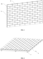
- the present invention relates to a building brick mounting system, particularly to a ceramic tile hanging system.
- Ceramic tiles are typically produced by high-temperature firing, using high-quality clay, purple sand clay, and other materials. Compared to traditional clay bricks, ceramic tiles have a finer texture, more stable color, and elegant lines. They serve as an energy-efficient and environmentally friendly building facade material, being pollution-free, lightweight, high-strength, corrosion-resistant, with good seismic and freeze resistance, and sound insulation. This cleverly combines traditional ceramic culture with modern architecture, meeting national requirements for building energy efficiency.
- the present invention aims to provide a low-cost ceramic tile hanging system with a simple attachment structure that can stably deliver attachment force.
- the present invention provides a ceramic tile hanging system that effectively addresses the aforementioned issues.
- the present invention is implemented as follows: A ceramic tile hanging system, firmly attached to an installation surface, including mounting components and ceramic tiles.
- the mounting components are securely fixed on the installation surface.
- the mounting components include several fitting members extending upward from the top surface of the mounting components, and the fitting members are integrally formed with the mounting components;
- the ceramic tiles are hung on and attached to the mounting components, with the sides of the ceramic tiles being abutted against each other.
- Each of the ceramic tiles has an inclined groove, and the inclined groove is hooked onto and attached to the fitting members.
- the inclined groove includes a first mounting portion arranged on the side away from the ceramic tile decorative surface, and a second mounting portion extending from the first mounting portion into the interior of the ceramic tile.
- Each of the fitting members includes a first connecting portion extending upward from the mounting components.
- the first connecting portion is abutted against the first mounting portion, and a second connecting portion extending from the first connecting portion into the second mounting portion.
- the first mounting portion is inclined.
- the second mounting portion is in communication with and level with the horizontal plane.
- the first connecting portion is fitted into the first mounting portion, and the second connecting portion is fitted into the second mounting portion.
- each of the fitting members further includes a third connecting portion extending from the second connecting portion into the second mounting portion.
- one end of the inner side of the first mounting portion is linear, and the other end is slanted.
- the second mounting portion is in communication with and level with the horizontal plane.
- the first connecting portion is perpendicular to and abuts against the linear inner side of the first mounting portion.
- the second connecting portion is perpendicular to the first connecting portion.
- the third connecting portion is slanted upward from the second connecting portion, or alternatively, the third connecting portion is slanted downward from the second connecting portion.
- one end of the inner side of the first mounting portion is linear, and the other end is slanted.
- the second mounting portion is in communication with and level with the horizontal plane.
- the first connecting portion is perpendicular to and abuts against the linear inner side of the first mounting portion.
- the second connecting portion is slanted downward from the first connecting portion.
- the third connecting portion is slanted upward from the first connecting portion.
- one end of the inner side of the first mounting portion is linear, and the other end is slanted.
- the second mounting portion is in communication with and level with the horizontal plane.
- the first connecting portion is perpendicular to and abuts against the linear inner side of the first mounting portion.
- the second connecting portion is slanted downward from the first connecting portion.
- the third connecting portion is slanted downward from the first connecting portion.
- the first mounting portion is inclined, the second mounting portion tilts downward/upward from the first mounting portion.
- the first connecting portion is fitted into the first mounting portion.
- the second connecting portion is connected to and level with the horizontal plane.
- the third connecting portion is connected to upper portion or lower portion of the second connecting portion.
- the first mounting portion is inclined, the second mounting portion is slanted downward/upward from the first mounting portion.
- the first connecting portion is fitted into the first mounting portion.
- the second connecting portion is slanted downward from the first connecting portion.
- the third connecting portion is connected to upper portion or lower portion the second connecting portion.
- the mounting component is C-shaped steel, and several fitting members are evenly spaced along the C-shaped steel.
- the C-shaped steel is securely fixed to the keel, and the keel is securely fixed to the installation surface.
- the mounting components are mounting baseplates, and several fitting members are arranged on the mounting baseplates.
- the mounting baseplates are securely fixed to the installation surface, or alternatively, the mounting baseplates are securely fixed to the keel, and the keel is securely fixed to the installation surface.
- the present invention achieves a stable hanging of ceramic tiles by the design of inclined grooves on the tiles and corresponding fitting members on the mounting components.
- the corresponding mounting part and fitting part can be matched by vertical or horizontal insertion. This ensures that at least two pivot points on the inclined groove inside the ceramic tile coordinate with the fitting members on the mounting components.
- the result is a simple structure that achieves secure hanging of the ceramic tiles.
- the ceramic tiles are restricted by the mounting components in the vertical/horizontal direction, promoting mutual adherence between adjacent tiles in the horizontal/vertical direction.
- workers only need to secure and lock the mounting components first, followed by stacking layer by layer of ceramic tiles. This significantly accelerates both the mounting and removal processes. Additionally, due to the simplicity of the hanging structure, the overall cost is substantially reduced, making it more competitive in the market.
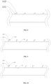
- the ceramic tile hanging system includes mounting components 1, mounting ear plate 2, and ceramic tiles 3.
- the mounting components 1 are securely fixed to the installation surface, including several fitting members 11 extending upward from the top surface of the mounting component 1, wherein the fitting members 11 are integrally formed with the mounting component 1.
- the mounting ear plate 2 is welded to the outer side of the mounting component 1.
- the ceramic tiles 3 are hung on and attached to on the mounting component 1.
- the ceramic tiles 3 is abutted to each other on their sides, and each ceramic tile 3 has an inclined groove 31 arranged on one side. The inclined groove 31 is hung on and attached to the fitting member 11.
- the inclined groove 31 includes a first mounting portion 311 arranged on the side away from the decorative surface of the ceramic tile 3 and a second mounting portion 312 extending from the first mounting portion 311 towards the interior of the ceramic tile 3.
- the fitting member 11 includes a first connecting portion 111 extending upward from the mounting component 1 and a second connecting portion 112 extending from the first connecting portion 111 into the second mounting portion 312. The first connecting portion 111 is abutted against the first mounting portion 311.
- the mounting component 1 can be directly mounted not only on conventional keels but also on uneven installation surfaces.
- the mounting component 1 can be directly secured to the uneven installation surface without the need for an intermediate keel framework. This makes the mounting more flexible.
- the ceramic tiles 3 may be hung vertically or horizontally by adjusting the positions of the corresponding fitting members 11 according to user needs.
- the fitting members 11 do not need to be separately welded to the mounting component 1 or locked onto the mounting component 1. Instead, they are an integral part of the mounting component 1.
- the mounting component 1 may have a conventional structure.
- the manufacturer can assemble the fitting members 11 according to the requirements of the building facade to be installed. For example, knowing the spacing between the tiles, the manufacturer can determine the specific layout of the fitting members 11.
- the fitting members 11 are cut into shape using a cutting machine. Subsequently, the fitting members 11 are rolled into a shape suitable for the tile hanging groove using a rolling machine. This ensures that the tile hanging system can be used immediately on-site without the need for on-site processing by professionals.
- the ceramic tiles 3 are grouped into an outer decorative brick layer 32 and an outer connecting brick layer 33. Both layers are made of fired clay and demonstrate good thermal insulation capabilities when installed as a curtain wall or other decorative surface.
- the outer decorative brick layer 32 may be colored or engraved with different patterns based on its purpose and the mounting environment, without specific limitations.
- the thickness of the outer connecting brick layer 33 should be at least 2-3 cm longer than the inclined groove 31 to ensure the overall strength of the outer connecting brick layer 33.
- the outer connecting brick layer 33 on each ceramic tile 3 is provided with two inclined grooves 31. This ensures that the hanging component can provide sufficient hanging force to hold both the outer decorative brick layer 32 and the outer connecting brick layer 33.
- the inclined grooves 31 are inclined. If the inclined grooves 31 are arranged as straight grooves or T-shaped grooves, it would require changing the fitting member 11, making it more complex and increasing the cost.
- the inclined grooves 31 are at least provided with a first mounting portion 311 and a second mounting portion 312.
- the fitting member 11 is provided with at least a first connecting portion 111 and a second connecting portion 112. The first connecting portion 111 and the second connecting portion 112 are fitted into the first mounting portion 311 and the second mounting portion 312, forming at least two fixed nodes. This way, even if one node deforms and loses its binding effect, the other node can still provide fixation.
- the fitting member 11 further includes a third connecting portion 113 extending from the second connecting portion 112 into the second mounting portion 312.
- the third connecting portion 113 forms a third fixed node within the second mounting portion 312.
- this embodiment utilizes a mechanical hanging, clamping, abutting, and fitting method, without using bolts throughout the hanging process. Even when installed at higher heights, workers can easily carry out the mounting without the need for prolonged pauses to tighten screws. Adhesives or glue are not used in this entire process, avoiding difficulties in disassembly due to the fixed effect of glue during replacement. In this embodiment, if it is necessary to replace the ceramic tile 3, only the corresponding column of ceramic tiles 3 needs to be taken down layer by layer from the top or side and then sequentially fitted with complete ceramic tiles 3.
- the ceramic tiles 3 are stacked layer by layer in the vertical direction, being secured by individual fitting members 11. They are fixed vertically by the fitting members 11, while horizontally, the ceramic tiles 3 abut against each other, forming a tight structure with mutual compression, resulting in a complete curtain wall structure.
- the hanging process mentioned above can also change direction.
- the ceramic tiles 3 may be fixed horizontally by the fitting members 11, while vertically, the ceramic tiles 3 abut against each other.
- one side of the outer connecting brick layer 33 extends a fitting block 3321, and the other side of the outer connecting brick layer 33 has a fitting groove 3322 that is inwardly recessed. Adjacent fitting blocks 3321 and fitting grooves 3322 are clamped and connected to each other. In this way, horizontally, adjacent outer connecting brick layers 33 are sequentially fixed by fitting blocks 3321 and fitting grooves 3322, and vertically, they are firmly held by hanging components, forming a stable facing structure.
- caulking is achieved directly through the ceramic tile itself.
- the outer decorative brick layer 32 and the outer connecting brick layer 33 are integrally formed.
- the outer connecting brick layer 33 is at least partially longer than the outer decorative brick layer 32, and the extended part serves as one side of the caulking.
- the fitting block 3321 extending from the outer connecting brick layer 332 is clamped into the fitting groove 3322. Although it is clamped in the fitting groove 3322, its width is relatively wide, and part of it remains exposed after clamping, serving as the other side of the caulking.
- the adjacent ceramic tiles thus form caulking on all four sides without the need for a separate caulking construction structure and steps, achieved through the tiles themselves.
- the settings of the mounting portions in the inclined groove 31 and the settings of the connecting portions in the fitting members 11 will also be adaptively adjusted accordingly. There are several embodiments. Firstly, the case where there is no third connecting portion 113 in the fitting member 11.
- the first mounting portion 311 is inclined, and the second mounting portion 312 is connected to and level with the first mounting portion 311 and the horizontal plane.
- the first connecting portion 111 is fitted into the first mounting portion 311, and the second connecting portion 112 is fitted into the second mounting portion 312.
- both the first mounting portion 311 and the second mounting portion 312 are designed as obtuse angles, and the first connecting portion 111 and the second connecting portion 112 are also designed as obtuse angles. This achieves fixation at two nodes and is suitable for places with a relatively mild environment and lightweight ceramic tiles.
- the fitting member 11 all includes a third connecting portion 113, meaning the fitting member 11 has three fixed nodes inside the inclined groove 31.
- the inner end of the first mounting portion 311 is a straight line, and the other end of the inner side of the first mounting portion 311 is a slanted line.
- the second mounting portion 312 is connected to and level with the first mounting portion 311 and the horizontal plane.
- the first connecting portion 111 is perpendicular to and abuts the straight line on the inner side of the first mounting portion 311
- the second connecting portion 112 is perpendicular to the first connecting portion 111
- the third connecting portion 113 is inclined upward or downward from the second connecting portion 112.
- both the second connecting portion 112 and the third connecting portion 113 are located on the inner side of the second mounting portion 312, forming two fixed points. Together with the fixation between the first connecting portion 111 and the first mounting portion 311, the cooperation between them is better, and the ceramic tile 3 can be tightly secured.
- Embodiment 2 differs from Embodiment 2 in that the second connecting portion 112 is inclined downward from the first connecting portion 111.
- the inner end of the first mounting portion 311 is a straight line
- the other end of the inner side of the first mounting portion 311 is a slanted line.
- the second mounting portion 312 is connected to and level with the first mounting portion 311 and the horizontal plane.
- the first connecting portion 111 is perpendicular to and abuts the straight line on the inner side of the first mounting portion 311, and the second connecting portion 112 is inclined downward from the first connecting portion 111, while the third connecting portion 113 is inclined upward from the first connecting portion 111. This achieves the same technical effect as the previous embodiments.
- This embodiment differs from embodiment 3 in that the third connecting portion 113 is inclined downward from the first connecting portion 111.
- the inner end of the first mounting portion 311 is a straight line
- the other end of the inner side of the first mounting portion 311 is a slanted line.
- the second mounting portion 312 is connected to and level with the first mounting portion 311 and the horizontal plane.
- the first connecting portion 111 is perpendicular to and abuts the straight line on the inner side of the first mounting portion 311, the second connecting portion 112 is inclined downward from the first connecting portion 111, and the third connecting portion 113 is inclined downward from the first connecting portion 111. This achieves the same technical effect as the previous embodiments.
- the inner end of the first mounting portion 311 is a straight line, and the other end of the inner side of the first mounting portion 311 is a slanted line.
- the purpose of this design is, first, the inclined design of the first mounting portion 311 ensures that workers can insert it with a certain angle during mounting, making the mounting smoother.
- the first connecting portion 111 can abut against the straight part of the first mounting portion 311, ensuring that the tiles 3 are closely attached to each other in daily use. Even if some tiles shake, the matching effect between the first connecting portion 111 and the first mounting portion 311 will slow down or even eliminate the shaking force.
- the first mounting portion 311 is inclined at one end and straight at the other end.
- the first mounting portion 311 can have other styles, for example:
- the first mounting portion 311 is inclined
- the second mounting portion 312 is inclined downward/upward from the first mounting portion 311
- the first connecting portion 111 is fitted into the first mounting portion 311
- the second connecting portion 112 is connected to the first connecting portion 111 and level with the horizontal plane
- the third connecting portion 113 is connected to upper portion/lower portion of the second connecting portion 112.
- the inclined arrangement of the first connecting portion 111 and the first mounting portion 311 corresponds to each other, while the second connecting portion 112 and the third connecting portion 113 are fixed inside the second mounting portion 312. This completes the fixation with three nodes in a single groove, providing a fixation effect that is at least equal to or surpasses similar products with complex groove styles in traditional brick structures.
- This embodiment differs from Embodiment 5 in that the second connecting portion 112 is inclined downward from the first connecting portion 111. Specifically, the first mounting portion 311 is inclined, the second mounting portion 312 is inclined downward/upward from the first mounting portion 311, the first connecting portion 111 is fitted into the first mounting portion 311, the second connecting portion 112 is inclined downward from the first connecting portion 111, and the third connecting portion 113 is connected to lower portion/upper portion of the second connecting portion 112.
- the second connecting portion 112 since the second connecting portion 112 is inclined downward from the first connecting portion 111, there is a bending force between the first connecting portion 111 and the second connecting portion 112, and there is another bending force between the third connecting portion 113 and the second connecting portion 112. This significantly improves the bending resistance and tensile strength of the entire fitting member 11. When combined with the inclined setting of the first connecting portion 111 and the first mounting portion 311, it effectively secures the tile 3.
- the mounting member 1 is a C-shaped steel 1A. Multiple of fitting members 11 are evenly spaced on the C-shaped steel 1A.
- the C-shaped steel 1A is fixed to the keel and the keel is fixed to the installation surface. In small buildings or local installation surfaces, the fixing method of C-shaped steel 1A may be used.
- the factory arranges the corresponding positions and spacing of the fitting members 11 according to the size of the customer's tiles 3 and transports them to the site for direct clamping to the keel or the installation surface. Then, the tiles 3 are gradually hung one by one.
- the style of the fitting members 11 opened on the C-shaped steel 1A may be any style mentioned in the above embodiments, and the style of the inclined groove 31 of the tiles 3 corresponding to them may also be any style mentioned in the above embodiments, which can be combined.
- the mounting member 1 is a mounting baseplate 1B.
- the mounting member 1 is a mounting baseplate 1B with multiple of fitting members 11 arranged on it.
- the mounting baseplate 1B is fixed to the installation surface or fixed to the keel.
- the style of the fitting members 11 may be any style mentioned in the above embodiments, and the style of the inclined groove 31 of the tiles 3 corresponding to them can also be any style mentioned in the above embodiments, which can be combined.
- C-shaped steel 1A or mounting baseplate 1B it is reinforced with reinforcing ribs to increase the overall strength when subjected to shaking force or vibration force.
Landscapes
- Engineering & Computer Science (AREA)
- Architecture (AREA)
- Civil Engineering (AREA)
- Structural Engineering (AREA)
- Chemical & Material Sciences (AREA)
- Ceramic Engineering (AREA)
- Dispersion Chemistry (AREA)
- Finishing Walls (AREA)
Applications Claiming Priority (2)
| Application Number | Priority Date | Filing Date | Title |
|---|---|---|---|
| CN202310074652.9A CN116427595B (zh) | 2023-01-30 | 2023-01-30 | 一种陶砖挂接系统 |
| CN202320142516.4U CN219491412U (zh) | 2023-01-30 | 2023-01-30 | 一种陶砖挂接系统 |
Publications (3)
| Publication Number | Publication Date |
|---|---|
| EP4407117A2 true EP4407117A2 (de) | 2024-07-31 |
| EP4407117A3 EP4407117A3 (de) | 2025-03-05 |
| EP4407117B1 EP4407117B1 (de) | 2026-04-08 |
Family
ID=89900715
Family Applications (1)
| Application Number | Title | Priority Date | Filing Date |
|---|---|---|---|
| EP24154814.8A Active EP4407117B1 (de) | 2023-01-30 | 2024-01-30 | Aufhängesystem für keramikfliesen |
Country Status (2)
| Country | Link |
|---|---|
| US (1) | US20240254777A1 (de) |
| EP (1) | EP4407117B1 (de) |
Family Cites Families (34)
| Publication number | Priority date | Publication date | Assignee | Title |
|---|---|---|---|---|
| US1388181A (en) * | 1920-01-22 | 1921-08-23 | Guimonneau Louis Henri | Building-wall |
| US2082314A (en) * | 1933-04-08 | 1937-06-01 | Nat Gypsum Co | Building construction |
| AT339011B (de) * | 1975-07-07 | 1977-09-26 | Leitl Werke Bauhuette | Bauwerkswand, insbesondere fassadenkonstruktion aus plattenformigen, z.b. keramischen bauelementen |
| JPS5482813A (en) * | 1977-12-15 | 1979-07-02 | Yoshio Yoshida | Method of placing tile |
| GB2155970A (en) * | 1984-03-01 | 1985-10-02 | Nippon Light Metal Co | Wall cladding |
| US4635424A (en) * | 1984-11-26 | 1987-01-13 | Les Enterprises Manuspec Inc. | One-piece fastener for securing a lining element in a removable manner on a carrying surface |
| JPH0663337B2 (ja) * | 1987-03-05 | 1994-08-22 | 元旦ビユーティ工業株式会社 | タイルブロツク外装壁 |
| US4890433A (en) * | 1987-12-15 | 1990-01-02 | Motokatsu Funaki | Tile mounting plate and tiled wall structure |
| US4916875A (en) * | 1988-07-18 | 1990-04-17 | Abc Trading Co., Ltd. | Tile-mount plate for use in wall assembly |
| US5029425A (en) * | 1989-03-13 | 1991-07-09 | Ciril Bogataj | Stone cladding system for walls |
| JPH05239902A (ja) * | 1992-02-27 | 1993-09-17 | Leo Kenchiku Sekkei Jimusho:Kk | 建築物の壁面の工法 |
| GB9724989D0 (en) * | 1997-11-26 | 1998-01-28 | Terrapin International Ltd | Improvements in cladding |
| US6258190B1 (en) * | 1999-06-03 | 2001-07-10 | Pete A. Sciarrino | Natural stone tile edging |
| DE60041662D1 (de) * | 2000-05-01 | 2009-04-09 | Masao Suzuki | Gebäude mit fassadenverkleidung |
| JP3490674B2 (ja) * | 2000-09-20 | 2004-01-26 | ニチハ株式会社 | 外壁施工構造 |
| DE102006033045A1 (de) * | 2006-07-14 | 2008-01-17 | Moeding Keramikfassaden Gmbh | Vorgehängte Fassadenkonstruktion |
| US8146303B2 (en) * | 2009-09-21 | 2012-04-03 | Brent Alan Gibson | Integrated decking member fastening track |
| WO2011040515A1 (ja) * | 2009-09-30 | 2011-04-07 | ケイミュー株式会社 | 外装材取付金具及び外装材取付構造 |
| US9109368B2 (en) * | 2011-06-15 | 2015-08-18 | Duncan MacKenzie | Rain screen siding system |
| JP5358624B2 (ja) * | 2011-07-01 | 2013-12-04 | Wpcコーポレーション株式会社 | パネル用の固定金具 |
| US9016020B1 (en) * | 2014-04-15 | 2015-04-28 | Jisong Yang | Thin brick panel assembly system |
| CN203924585U (zh) * | 2014-04-30 | 2014-11-05 | 蔡逸民 | 密封条及地板砖拼接单元 |
| US9896851B1 (en) * | 2015-04-14 | 2018-02-20 | The Matworks Copmany LLC | Hard surface veneer and wood polymer composite flooring tile |
| CN105507537B (zh) * | 2015-07-03 | 2019-04-05 | 陆星但 | 自由装拆、大小自由组合的建筑装饰面板干挂结构 |
| GB2540443B (en) * | 2015-11-06 | 2018-10-31 | Thomas Smart Hugh | A kit of parts for fixing a plurality of cladding boards to a surface |
| NL2018970B1 (en) * | 2017-05-23 | 2018-12-04 | Innovations 4 Flooring Holding Nv | Multi-purpose tile system |
| KR101937711B1 (ko) * | 2017-12-22 | 2019-01-11 | 주식회사 유토플러스 | 마감재 건식시공 시스템 |
| EP3623542B1 (de) * | 2018-09-12 | 2022-08-31 | Moeding Keramikfassaden GmbH | Rüttelfeste fassadenkonstruktion |
| NL2021887B1 (en) * | 2018-10-26 | 2020-05-13 | I4F Licensing Nv | Multi-purpose tile system, tile covering, and tile |
| US11905713B2 (en) * | 2019-04-30 | 2024-02-20 | Hunter Douglas Inc. | Coupling system for mounting tiles to a building |
| CA3126251A1 (en) * | 2020-07-30 | 2022-01-30 | Dryvit Systems, Inc. | Mounted panel systems and methods |
| TWI771116B (zh) * | 2021-07-22 | 2022-07-11 | 簡幸美 | 壁材乾掛扣件 |
| KR102739470B1 (ko) * | 2022-03-03 | 2024-12-06 | 주식회사 유토 | 마감재 건식 시공 시스템 |
| EP4407116B1 (de) * | 2023-01-30 | 2025-07-02 | Haoheng (Fujian) Building Materials Technology Co., Ltd. | Aufhängesystem für keramikfliesen |
-
2024
- 2024-01-30 EP EP24154814.8A patent/EP4407117B1/de active Active
- 2024-01-30 US US18/427,490 patent/US20240254777A1/en active Pending
Also Published As
| Publication number | Publication date |
|---|---|
| EP4407117B1 (de) | 2026-04-08 |
| EP4407117A3 (de) | 2025-03-05 |
| US20240254777A1 (en) | 2024-08-01 |
Similar Documents
| Publication | Publication Date | Title |
|---|---|---|
| EP4407116B1 (de) | Aufhängesystem für keramikfliesen | |
| CN109267671A (zh) | 一种室内墙体系统的装修方法 | |
| CN110512821B (zh) | 一种无基板瓷砖安装结构及其安装方法 | |
| CN204112653U (zh) | 一种薄装饰板用挂件、结构单元及无龙骨结构体系 | |
| EP4407117A2 (de) | Aufhängesystem für keramikfliesen | |
| CN219491412U (zh) | 一种陶砖挂接系统 | |
| CN219298544U (zh) | 一种陶砖挂接系统 | |
| CN212427880U (zh) | 一种墙面挂装系统 | |
| CN209891542U (zh) | 一种装配式墙体安装组件及墙体 | |
| CN201292595Y (zh) | 建筑装饰用支撑骨架 | |
| CN210597833U (zh) | 一种装配式吊顶结构 | |
| CN113585568B (zh) | 一种陶瓦干挂式幕墙外立面结构 | |
| CN209443633U (zh) | 墙体外饰面装配式单元集成复合板块及其连接构造 | |
| CN116427595B (zh) | 一种陶砖挂接系统 | |
| CN116446568B (zh) | 一种陶砖挂接系统 | |
| CN218323307U (zh) | 用于装配式预制构件的调平装置及包含其的节能墙体 | |
| CN216305125U (zh) | 一种新型装配式墙板及具有该墙板的建筑结构 | |
| CN112922220B (zh) | 一种带灯槽的吊顶结构及其施工方法 | |
| CN112814323B (zh) | 一体化组合挂件 | |
| CN215889126U (zh) | 用于疏松墙体的加强型一体板外墙保温装饰系统 | |
| CN213204597U (zh) | 一种斜屋面檐口收口处的石材幕墙 | |
| CN222822747U (zh) | 一种复合砖装饰安装结构 | |
| CN210530044U (zh) | 用于灌浆墙的快装墙板、竖龙骨及灌浆墙 | |
| CN210659076U (zh) | 底杆、底盒装置及墙面板安装总成 | |
| CN223446533U (zh) | 一种混凝土预制装饰板及连接结构 |
Legal Events
| Date | Code | Title | Description |
|---|---|---|---|
| PUAI | Public reference made under article 153(3) epc to a published international application that has entered the european phase |
Free format text: ORIGINAL CODE: 0009012 |
|
| STAA | Information on the status of an ep patent application or granted ep patent |
Free format text: STATUS: REQUEST FOR EXAMINATION WAS MADE |
|
| 17P | Request for examination filed |
Effective date: 20240204 |
|
| AK | Designated contracting states |
Kind code of ref document: A2 Designated state(s): AL AT BE BG CH CY CZ DE DK EE ES FI FR GB GR HR HU IE IS IT LI LT LU LV MC ME MK MT NL NO PL PT RO RS SE SI SK SM TR |
|
| PUAL | Search report despatched |
Free format text: ORIGINAL CODE: 0009013 |
|
| STAA | Information on the status of an ep patent application or granted ep patent |
Free format text: STATUS: EXAMINATION IS IN PROGRESS |
|
| AK | Designated contracting states |
Kind code of ref document: A3 Designated state(s): AL AT BE BG CH CY CZ DE DK EE ES FI FR GB GR HR HU IE IS IT LI LT LU LV MC ME MK MT NL NO PL PT RO RS SE SI SK SM TR |
|
| RIC1 | Information provided on ipc code assigned before grant |
Ipc: E04F 13/24 20060101ALI20250130BHEP Ipc: E04F 13/14 20060101ALI20250130BHEP Ipc: E04F 13/12 20060101ALI20250130BHEP Ipc: E04F 13/09 20060101ALI20250130BHEP Ipc: E04F 13/08 20060101ALI20250130BHEP Ipc: E04F 13/077 20060101ALI20250130BHEP Ipc: E04F 13/076 20060101AFI20250130BHEP |
|
| 17Q | First examination report despatched |
Effective date: 20250217 |
|
| RIN1 | Information on inventor provided before grant (corrected) |
Inventor name: SHUI, SIJUN Inventor name: SU, YONGRUN Inventor name: HONG, QIUYAO |
|
| GRAP | Despatch of communication of intention to grant a patent |
Free format text: ORIGINAL CODE: EPIDOSNIGR1 |
|
| STAA | Information on the status of an ep patent application or granted ep patent |
Free format text: STATUS: GRANT OF PATENT IS INTENDED |
|
| INTG | Intention to grant announced |
Effective date: 20251028 |
|
| GRAS | Grant fee paid |
Free format text: ORIGINAL CODE: EPIDOSNIGR3 |
|
| GRAA | (expected) grant |
Free format text: ORIGINAL CODE: 0009210 |
|
| STAA | Information on the status of an ep patent application or granted ep patent |
Free format text: STATUS: THE PATENT HAS BEEN GRANTED |
|
| AK | Designated contracting states |
Kind code of ref document: B1 Designated state(s): AL AT BE BG CH CY CZ DE DK EE ES FI FR GB GR HR HU IE IS IT LI LT LU LV MC ME MK MT NL NO PL PT RO RS SE SI SK SM TR |
|
| REG | Reference to a national code |
Ref country code: CH Ref legal event code: F10 Free format text: ST27 STATUS EVENT CODE: U-0-0-F10-F00 (AS PROVIDED BY THE NATIONAL OFFICE) Effective date: 20260408 Ref country code: GB Ref legal event code: FG4D |