EP4407004A1 - Polymerzusammensetzung mit recyceltem polyamid und elektronische vorrichtung und schutzgehäuse für elektronische vorrichtung damit - Google Patents
Polymerzusammensetzung mit recyceltem polyamid und elektronische vorrichtung und schutzgehäuse für elektronische vorrichtung damit Download PDFInfo
- Publication number
- EP4407004A1 EP4407004A1 EP23753123.1A EP23753123A EP4407004A1 EP 4407004 A1 EP4407004 A1 EP 4407004A1 EP 23753123 A EP23753123 A EP 23753123A EP 4407004 A1 EP4407004 A1 EP 4407004A1
- Authority
- EP
- European Patent Office
- Prior art keywords
- polyamide
- electronic device
- polymer composition
- recycled
- weight
- Prior art date
- Legal status (The legal status is an assumption and is not a legal conclusion. Google has not performed a legal analysis and makes no representation as to the accuracy of the status listed.)
- Pending
Links
Images


Classifications
-
- C—CHEMISTRY; METALLURGY
- C08—ORGANIC MACROMOLECULAR COMPOUNDS; THEIR PREPARATION OR CHEMICAL WORKING-UP; COMPOSITIONS BASED THEREON
- C08L—COMPOSITIONS OF MACROMOLECULAR COMPOUNDS
- C08L77/00—Compositions of polyamides obtained by reactions forming a carboxylic amide link in the main chain; Compositions of derivatives of such polymers
- C08L77/10—Polyamides derived from aromatically bound amino and carboxyl groups of amino-carboxylic acids or of polyamines and polycarboxylic acids
-
- C—CHEMISTRY; METALLURGY
- C08—ORGANIC MACROMOLECULAR COMPOUNDS; THEIR PREPARATION OR CHEMICAL WORKING-UP; COMPOSITIONS BASED THEREON
- C08J—WORKING-UP; GENERAL PROCESSES OF COMPOUNDING; AFTER-TREATMENT NOT COVERED BY SUBCLASSES C08B, C08C, C08F, C08G or C08H
- C08J11/00—Recovery or working-up of waste materials
- C08J11/04—Recovery or working-up of waste materials of polymers
- C08J11/06—Recovery or working-up of waste materials of polymers without chemical reactions
-
- C—CHEMISTRY; METALLURGY
- C08—ORGANIC MACROMOLECULAR COMPOUNDS; THEIR PREPARATION OR CHEMICAL WORKING-UP; COMPOSITIONS BASED THEREON
- C08L—COMPOSITIONS OF MACROMOLECULAR COMPOUNDS
- C08L23/00—Compositions of homopolymers or copolymers of unsaturated aliphatic hydrocarbons having only one carbon-to-carbon double bond; Compositions of derivatives of such polymers
- C08L23/02—Compositions of homopolymers or copolymers of unsaturated aliphatic hydrocarbons having only one carbon-to-carbon double bond; Compositions of derivatives of such polymers not modified by chemical after-treatment
- C08L23/04—Homopolymers or copolymers of ethene
- C08L23/08—Copolymers of ethene
- C08L23/0846—Copolymers of ethene with unsaturated hydrocarbons containing atoms other than carbon or hydrogen
- C08L23/0869—Copolymers of ethene with unsaturated hydrocarbons containing atoms other than carbon or hydrogen with unsaturated acids, e.g. [meth]acrylic acid; with unsaturated esters, e.g. [meth]acrylic acid esters
- C08L23/0884—Epoxide-containing esters
-
- C—CHEMISTRY; METALLURGY
- C08—ORGANIC MACROMOLECULAR COMPOUNDS; THEIR PREPARATION OR CHEMICAL WORKING-UP; COMPOSITIONS BASED THEREON
- C08L—COMPOSITIONS OF MACROMOLECULAR COMPOUNDS
- C08L23/00—Compositions of homopolymers or copolymers of unsaturated aliphatic hydrocarbons having only one carbon-to-carbon double bond; Compositions of derivatives of such polymers
- C08L23/02—Compositions of homopolymers or copolymers of unsaturated aliphatic hydrocarbons having only one carbon-to-carbon double bond; Compositions of derivatives of such polymers not modified by chemical after-treatment
- C08L23/18—Homopolymers or copolymers of hydrocarbons having four or more carbon atoms
-
- C—CHEMISTRY; METALLURGY
- C08—ORGANIC MACROMOLECULAR COMPOUNDS; THEIR PREPARATION OR CHEMICAL WORKING-UP; COMPOSITIONS BASED THEREON
- C08L—COMPOSITIONS OF MACROMOLECULAR COMPOUNDS
- C08L23/00—Compositions of homopolymers or copolymers of unsaturated aliphatic hydrocarbons having only one carbon-to-carbon double bond; Compositions of derivatives of such polymers
- C08L23/26—Compositions of homopolymers or copolymers of unsaturated aliphatic hydrocarbons having only one carbon-to-carbon double bond; Compositions of derivatives of such polymers modified by chemical after-treatment
-
- C—CHEMISTRY; METALLURGY
- C08—ORGANIC MACROMOLECULAR COMPOUNDS; THEIR PREPARATION OR CHEMICAL WORKING-UP; COMPOSITIONS BASED THEREON
- C08L—COMPOSITIONS OF MACROMOLECULAR COMPOUNDS
- C08L77/00—Compositions of polyamides obtained by reactions forming a carboxylic amide link in the main chain; Compositions of derivatives of such polymers
- C08L77/02—Polyamides derived from omega-amino carboxylic acids or from lactams thereof
-
- G—PHYSICS
- G06—COMPUTING OR CALCULATING; COUNTING
- G06F—ELECTRIC DIGITAL DATA PROCESSING
- G06F1/00—Details not covered by groups G06F3/00 - G06F13/00 and G06F21/00
- G06F1/16—Constructional details or arrangements
- G06F1/1613—Constructional details or arrangements for portable computers
- G06F1/1626—Constructional details or arrangements for portable computers with a single-body enclosure integrating a flat display, e.g. Personal Digital Assistants [PDAs]
-
- G—PHYSICS
- G06—COMPUTING OR CALCULATING; COUNTING
- G06F—ELECTRIC DIGITAL DATA PROCESSING
- G06F1/00—Details not covered by groups G06F3/00 - G06F13/00 and G06F21/00
- G06F1/16—Constructional details or arrangements
- G06F1/1613—Constructional details or arrangements for portable computers
- G06F1/163—Wearable computers, e.g. on a belt
-
- G—PHYSICS
- G06—COMPUTING OR CALCULATING; COUNTING
- G06F—ELECTRIC DIGITAL DATA PROCESSING
- G06F1/00—Details not covered by groups G06F3/00 - G06F13/00 and G06F21/00
- G06F1/16—Constructional details or arrangements
- G06F1/1613—Constructional details or arrangements for portable computers
- G06F1/1633—Constructional details or arrangements of portable computers not specific to the type of enclosures covered by groups G06F1/1615 - G06F1/1626
- G06F1/1656—Details related to functional adaptations of the enclosure, e.g. to provide protection against EMI, shock, water, or to host detachable peripherals like a mouse or removable expansions units like PCMCIA cards, or to provide access to internal components for maintenance or to removable storage supports like CDs or DVDs, or to mechanically mount accessories
-
- C—CHEMISTRY; METALLURGY
- C08—ORGANIC MACROMOLECULAR COMPOUNDS; THEIR PREPARATION OR CHEMICAL WORKING-UP; COMPOSITIONS BASED THEREON
- C08L—COMPOSITIONS OF MACROMOLECULAR COMPOUNDS
- C08L2203/00—Applications
- C08L2203/20—Applications use in electrical or conductive gadgets
- C08L2203/206—Applications use in electrical or conductive gadgets use in coating or encapsulating of electronic parts
-
- C—CHEMISTRY; METALLURGY
- C08—ORGANIC MACROMOLECULAR COMPOUNDS; THEIR PREPARATION OR CHEMICAL WORKING-UP; COMPOSITIONS BASED THEREON
- C08L—COMPOSITIONS OF MACROMOLECULAR COMPOUNDS
- C08L2207/00—Properties characterising the ingredient of the composition
- C08L2207/20—Recycled plastic
-
- G—PHYSICS
- G06—COMPUTING OR CALCULATING; COUNTING
- G06F—ELECTRIC DIGITAL DATA PROCESSING
- G06F2200/00—Indexing scheme relating to G06F1/04 - G06F1/32
- G06F2200/16—Indexing scheme relating to G06F1/16 - G06F1/18
- G06F2200/163—Indexing scheme relating to constructional details of the computer
- G06F2200/1633—Protecting arrangement for the entire housing of the computer
-
- Y—GENERAL TAGGING OF NEW TECHNOLOGICAL DEVELOPMENTS; GENERAL TAGGING OF CROSS-SECTIONAL TECHNOLOGIES SPANNING OVER SEVERAL SECTIONS OF THE IPC; TECHNICAL SUBJECTS COVERED BY FORMER USPC CROSS-REFERENCE ART COLLECTIONS [XRACs] AND DIGESTS
- Y02—TECHNOLOGIES OR APPLICATIONS FOR MITIGATION OR ADAPTATION AGAINST CLIMATE CHANGE
- Y02W—CLIMATE CHANGE MITIGATION TECHNOLOGIES RELATED TO WASTEWATER TREATMENT OR WASTE MANAGEMENT
- Y02W30/00—Technologies for solid waste management
- Y02W30/50—Reuse, recycling or recovery technologies
- Y02W30/62—Plastics recycling; Rubber recycling
Definitions
- polymer compositions more specifically, polymer compositions including recycled polyamide and an electronic device and protective case for the electronic device including the same.
- Polymers are inexpensive and have good machinability and physical properties, and so they are used in various fields. Because of their good strength, impact resistance, non-conductivity, and radio wave transmission, polymers are utilized in applications such as frames that support internal components of electronic devices and/or cases that protect the exterior of electronic devices. In particular, polyamide-based polymers are widely used in the fields described above because of their high tensile strength, impact strength, and easy molding.
- polymer scrap such as gates, sprues, and/or runners may be generated in the process of injecting a resin into a mold for injection molding.
- polymer waste may occur at the end of the life cycle of a polymer product.
- the above-mentioned polymer scrap and polymer waste are incinerated, landfilled, or dumped, air pollution, soil pollution, and marine plastic pollution may be caused. Accordingly, the above-described polymer scrap and waste may be collected and recycled by being input as a raw material in the production of a polymer product.
- Various embodiments disclosed in this document may provide a polymer composition including a recycled polyamide that has improved physical properties and appearance and an electronic device and a protective case including the same.
- the polymer composition according to various embodiments of the present disclosure may comprise a recycled polyamide, a new polyamide including at least one polyamide component, a glycidyl group-modified ethylene-octene-based copolymer, and an inorganic filler.
- the recycled polyamide may include a polyamide collected from marine plastic waste.
- 10 to 30% by weight of the recycled polyamide, 1 to 50% by weight of the new polyamide, 0.1 to 10% by weight of the glycidyl group-modified ethylene-octene-based copolymer, and 30 to 70% by weight of the inorganic filler may be included.
- the new polyamide may include polyamide PA6 and a modified polyamide having a benzene ring.
- the modified polyamide may include at least one of polyamide PA6I, a copolymer of polyamide PA6I and PA6T, and polyamide MXD6. In some embodiments, 1 to 30% by weight of the polyamide PA6 and 1 to 20% by weight of the modified polyamide may be included.
- An electronic device may comprise a display disposed toward a first direction; a housing including an inner space having an opening opened in the first direction; a substrate portion disposed inside the housing; and a support member supporting the substrate portion with respect to the housing and including a non-conductive material, wherein the support member includes a polymer composition including a recycled polyamide, a new polyamide including at least one polyamide component, glycidyl group-modified ethylene-octene-based copolymer, and an inorganic filler.
- the recycled polyamide may include a polyamide collected from marine plastic waste.
- the new polyamide may include polyamide PA6 and a modified polyamide having a benzene ring.
- the polymer composition may have a tensile strength of 2300 kgf/cm 2 or more. In some embodiments, the polymer composition may have a notched Izod impact strength of 14 kgf cm/cm or more. In some embodiments, the polymer composition may have a thermal stability with a weight loss of 2.5% or less when heated at 230°C for 30 minutes. In some embodiments, the polymer composition may have a moisture absorption of 1% by weight or less when immersed in water for 24 hours.
- a protective case according to other embodiments of the present disclosure may comprise a polymer composition including a recycled polyamide, a new polyamide including at least one polyamide component, glycidyl group-modified ethylene-octene-based copolymer,
- the protective case is disposed adjacent to at least a portion of an external surface of an electronic device to protect the electronic device from external impact.
- the recycled polyamide may include a polyamide collected from marine plastic waste.
- the new polyamide may include polyamide PA6 and a modified polyamide having a benzene ring.
- a polymer composition that recycles polyamide waste and improves physical properties and appearance and an electronic device and a protective case including the same may be provided.
- the polymer composition according to various embodiments of the present disclosure may include a recycled polyamide, a new polyamide, a glycidyl group-modified ethylene-octene-based copolymer, and an inorganic filler.
- the recycled polyamide may include polyamide scrap such as runners, sprues and/or gates generated during the injection molding process, and materials molded from polyamide waste such as marine waste plastics, waste nets, waste fabrics, waste cloths, waste fibers, and/or waste films.
- the recycled polyamide may include polyamide 6 (PA6).
- PA6 polyamide 6
- the recycled polyamide may be, but is not limited to, crystalline, semi-crystalline, amorphous, or a mixture thereof.
- the polymer composition of the present disclosure may recycle polyamide waste by including recycled polyamide. For example, it is possible to contribute to the reduction of marine plastic pollution by collecting and recycling waste nets made of polyamide 6, which account for the highest proportion of marine plastic pollutants.
- recycled polyamide may be included in the polymer composition in an amount of 10 to 30% by weight or less. In the case that the content of the recycled polyamide exceeds the above numerical range, mechanical properties of the polymer composition may be deteriorated or of poor appearance because gas generation may become severe.
- the new polyamide may be a polyamide resin prepared directly from a polyamide raw material without undergoing a recycling process.
- the new polyamide may include polyamide 6 (PA6), polyamide 66 (PA66), modified polyamide, or various polymers having amide linkages similar thereto.
- the polymer composition of the present disclosure may contain 1 to 30% by weight of the new polyamide.
- the new polyamide may include polyamide 6 (PA6).
- Polyamide 6 may be synthesized by dehydration condensation polymerization of 6-aminohexanoic acid into a polymer having a molecular structure as shown in Formula 1 below.
- n is an arbitrary integer.
- the new polyamide may include various modified polyamides.
- the modified polyamide as a polyamide including a benzene ring in the main chain, may have a structure in which an aromatic dicarboxylic acid monomer and an aliphatic or alicyclic diamine are condensation-polymerized, or an aromatic diamine and an aliphatic or alicyclic dicarboxylic acid are condensation-polymerized.
- the new polyamide may include at least one of polyamide PA6I, polyamide PA6I/PA6T, and/or polyamide MXD6.
- the polyamide PA6I may be poly-isophthalamide obtained by polymerizing hexamethylene diamine and isophthalic acid and having a molecular structure as shown in Formula 2 below.
- n is an arbitrary integer.
- the polyamide PA6I/PA6T may be, for example, a copolymer of terephthalamide and isophthalamide and have a molecular structure as shown in the following Formula 3 below.
- n and m are arbitrary integers.
- the polyamide PA6I/6T may be a block copolymer, an alternating copolymer, or a random copolymer.
- the polymer of terephthalamide tends to have a high degree of crystallinity, whereas the polymer of isophthalamide tends to have a low degree of crystallinity; therefore the polyamide PA6I/6T, the copolymer of terephthalamide and isophthalamide, may improve the physical properties of the polymer composition by adjusting the crystallinity optimally.
- the polyamide MXD6 may be a polymer obtained by dehydration condensation polymerization of xylenediamine and adipic acid and have a molecular structure as shown in Formula 4 below.
- n is an arbitrary integer.
- the modified polyamide may include a benzene ring in the monomer.
- the modified polyamide including a benzene ring By mixing the modified polyamide including a benzene ring into the polymer composition, it is possible to increase the chemical resistance of the polymer composition and lower the water absorbance. Since the amide bond is vulnerable to hydrolysis, durability and mechanical properties of the polymer composition and the injection product including the same may be improved by lowering the hygroscopicity of the polyamide.
- the polymer composition may include 1 to 20% by weight of modified polyamide. In the case that the content of the modified polyamide is less than the above range, the effect of improving chemical resistance and reducing hygroscopicity according to the inclusion of the modified polyamide may not appear.
- the modified polyamide included in the polymer composition may be crystalline, semi-crystalline, or amorphous.
- the polymer composition may include 5 to 15% by weight or 5 to 10% by weight of modified polyamide.
- mechanical properties e.g., the tensile strength, the impact strength
- a molded article prepared from a recycled polyamide resin composition including the same may be further improved.
- a glycidyl group-modified ethylene-octene-based copolymer may be, for example, the grafted glycidyl group by bonding glycidyl methacrylate (GMA) to a polyethylene octene copolymer (poly (ethylene octene)).
- GMA glycidyl methacrylate
- poly (ethylene octene) poly (ethylene octene)
- the glycidyl group-modified ethylene-octene-based copolymer may have a structure as shown in Formula 5 below.
- the glycidyl methacrylate content of the glycidyl group-modified ethylene-octene-based copolymer may be 2 to 20% by weight, specifically 8 to 10% by weight, but it is not necessarily limited thereto.
- the glycidyl group-modified ethylene-octene-based copolymer may have an average molecular weight of 50,000 to 350,000 g/mol, specifically 100,000 to 300,000 g/mol, more specifically 150,000 to 250,000 g /mol. In the case that the average molecular weight of the glycidyl group-modified ethylene-octene-based copolymer satisfies the above numerical range, mechanical properties of the polymer composition including the same may be improved.
- the glycidyl group-modified ethylene-octene copolymer may increase the melt viscosity and melt tension of the polymer composition including the recycled polyamide, and it may improve thermal stability and appearance.
- the glycidyl group grafted to the glycidyl group-modified ethylene-octene-based copolymer may extend the polyamide chain by, for example, a ring-opening reaction as shown in Formula 6 below.
- PA means a polyamide chain.
- the ethylene-octene chain of the glycidyl group-modified ethylene-octene copolymer is omitted for clarity.
- the recycled polyamide may undergo degradation in which polymer chains break and shorten because of various external adverse effects, such as exposure to heat during injection molding, exposure to sunlight during use and after disposal, and/or hydrolysis by exposure to moisture. Because of the above-described deterioration, there may be gas generation from the recycled polyamide included in the polymer composition during injection molding due to a decrease in thermal stability, injection molding burr due to a decrease in melt viscosity and melt tension due to shortening of the polymer chain, a decrease in tensile strength and impact strength due to shortening of the polymer chain, and an increase in hygroscopicity.
- the glycidyl group-modified ethylene-octene copolymer may act as a chain extender for the deteriorated polymer chain of the recycled polyamide. Therefore, the polymer composition containing the glycidyl group-modified ethylene-octene copolymer may reduce the risk of deterioration of mechanical properties and quality because of the use of recycled polyamide through the reduction of the gas generation defect during injection by the improvement of thermal stability, reduction of the injection molding burr by increasing the melt viscosity and melt tension, increase of the tensile strength and impact strength, and reduction of the hygroscopicity.
- the polymer composition of the present disclosure may include 0.1 to 10% by weight of a glycidyl group-modified ethylene-octene-based copolymer.
- melt viscosity and melt tension of the polymer composition may be optimally adjusted to provide optimal fluidity for extrusion molding of the polymer composition.
- the inorganic filler may be included in the polymer composition to strengthen mechanically the polymer composition and control the density.
- the inorganic filler may include a fibrous or needle-like inorganic material such as, for example, glass fiber, carbon fiber, mineral wool, or alastonite.
- the inorganic filler may include a granular or plate-like solid inorganic material such as talc, clay, kaolin, mica, and calcium carbonate.
- the particle shape of the inorganic filler may have a ratio of a minor axis to a major axis of 1: 1 to 1:10, specifically 1:2 to 1:8.
- the length of the inorganic filler may be 1 to 5 mm, specifically 2 to 4 mm. In the case that the length of the inorganic filler is smaller than the above range, the strengthening effect of the polymer by the inorganic filler is reduced.
- the length of the inorganic filler exceeds the above range, impregnation of the polyamide and the inorganic filler may be incomplete, or the possibility that the inorganic filler may be aggregated in some areas of the injection-molded product may increase because of entanglement between the inorganic fillers.
- the polymer composition may include 30 to 70% by weight of inorganic filler. In the case that the content of the inorganic filler is within the above range, mechanical properties of the polymer composition may be improved.
- the polymer composition of the present disclosure may further include additives, if necessary, in a range that does not impair the effects of the present disclosure.
- the additives may include, but are not limited to, an antioxidant, a lubricant, a heat stabilizer, a flame retardant, a weathering stabilizer, an antistatic agent, a release agent, a colorant, and/or a mixture thereof.
- the additive may be included in an amount of 0.1 to 20% by weight, specifically 0.5 to 10% by weight.
- the type of the antioxidant is not particularly limited, but it may include a phenolic antioxidant.
- a hindered phenol antioxidant may be mentioned, and a commercialized example may include Irganox 1010, Irganox 1098, and Irganox 245, but it is not necessarily limited thereto.
- the lubricant is used without limitation as long as it is commonly used, and, for example, polyethylene wax may be used.
- the heat stabilizer may be used without limitation as long as it is commonly used, and, for example, trimethyl phosphite, triethyl phosphite, tris(nonylphenyl) phosphite, trimethyl phosphate, and tris(2,4-di-tert-butylphenyl) phosphite may be mentioned, but it is not necessarily limited thereto.
- polymer compositions of various embodiments including recycled polyamide were manufactured, and properties and quality were compared with those of comparative examples.
- Specific configurations of the embodiments and the comparative examples are described in Table 1.
- the polymer compositions of the embodiments and the comparative examples were prepared by mixing the components of Table 1 below with a mixer to manufacture pellets, and the specimens were manufactured through injection molding of the pellets.
- EOR-GMA represents a glycidyl group-modified ethylene-octene-based copolymer.
- PA6I/6T, PA6I, and MXD6 are modified polyamides containing a benzene ring.
- the unit of the indicated content is % by weight.
- various examples of the resin composition of the present disclosure contain 20 to 30% by weight of recycled polyamide, 1 to 3% by weight of a glycidyl group-modified ethylene-octene-based copolymer, and 50 to 70% of glass fiber as an inorganic filler.
- the tensile strength was measured using a tensile tester for dumbbell-type specimen in accordance with KS M ISO 527.
- the impact strength was measured by making a notch in a 1/8" thick specimen in accordance with ASTM D256 and measuring the notched Izod impact strength.
- the specimen was dried in an oven at 50°C for 24 hours and weighed, after which the test specimen was immersed in water at 23°C for 24 hours, then removed, wiped with a cloth, and immediately weighed.
- the thermal stability was measured by the weight loss through a thermogravimetric analyzer with the temperature maintained at 320°C for 30 minutes.
- Comparative Example 1 using only recycled polyamide recovered from marine waste showed significantly lower tensile strength and impact strength compared with the present disclosure, and it can also be seen that that, in Comparative Example 3 to Comparative Example 5 prepared by mixing recycled polyamide and new polyamide, the tensile strength and impact strength are somewhat lower than those of the present disclosure. It can be seen that Comparative Example 2 prepared as a control that does not contain the recycled polyamide has relatively high tensile strength and impact strength; therefore, the low physical properties of Comparative Examples 1 and 3 to 5 are because of the inclusion of the recycled polyamide. Accordingly, it can be seen that the polymer composition of the present disclosure may solve the problem of deterioration of physical properties that occurs during recycling of recycled polyamide collected from plastic waste such as marine waste.
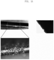
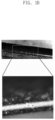
- FIGS. 1a and 1b are views comparing the appearance of products manufactured by injecting a polymer composition according to an embodiment of the present disclosure and a polymer composition according to a comparative example including recycled polyamide, respectively.
- the polymer composition of the present disclosure maintained an optimal state of melt viscosity and melt tension, and improved thermal stability, so that surface defects because of gas generation did not appear. Therefore, it can be seen that, while recycling recycled polyamide such as marine waste, this may help to expand the recycling range of recycled polyamide by reducing the quality defects that occur during recycling and, ultimately, may help to recycle marine plastic waste.
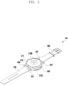
- FIG. 2 is a perspective view of a front surface of an electronic device according to some embodiments of the present disclosure.
- FIG. 3 is a perspective view of a rear surface of the electronic device of FIG. 2 .
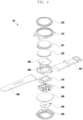
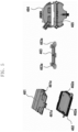
- FIG. 4 is an exploded perspective view of the electronic device of FIG. 2 .
- an electronic device 101 may include a housing 210 including a first side (or front side) 210A, a second side (or rear side) 210B, and a side surface 210C surrounding a space between the first surface 210A and the second surface 210B; and it may include binding members 250 and 260 that are connected to at least a portion of the housing 210 and composed to allow the electronic device 101 to be detachably attached to a portion (e.g., wrist, ankle) of a user's body.
- the binding members 250 and 260 may be, for example, a strap wound around a user's wrist to fix the electronic device 101.
- the housing may refer to a structure that forms part of the first surface 210A, the second surface 210B, and the side surface 210C of FIG. 2 .
- the first surface 210A may be formed by the front plate 201 (e.g., a glass plate including various coating layers or a polymer plate) at least a portion of which is substantially transparent.
- the second surface 210B may be formed by a substantially opaque back plate 207.
- the back plate 207 may be formed by, for example, coated or tinted glass, ceramic, polymer, metal (e.g., aluminum, stainless steel (STS), or magnesium), or a combination of at least two of the foregoing.
- the side surface 210C is coupled to the front plate 201 and the rear plate 207 and may be formed by a side bezel structure (or "side member") 206 including a metal and/or a polymer.
- the back plate 207 and the side bezel structure 206 are integrally formed and may include the same material (e.g., a metal material such as aluminum).
- the binding members 250 and 260 may be formed of various materials and shapes. A woven fabric, leather, rubber, synthetic resin, metal, ceramic, or a combination of at least two of the above materials may be used to form an integral and a plurality of unit links to be able to flow with each other.
- the electronic device 101 may include at least one of a display 220 (refer to FIG. 3 ), audio modules 205 and 208, a sensor module 211, key input devices 202, 203 and 204, and a connector hole (209).
- the electronic device 101 may omit at least one of the components (e.g., the key input devices 202, 203 and 204, the connector hole 209, or the sensor module 211) or may include other constitution elements additionally.
- the display 220 may be visually exposed through a substantial portion of the front plate 201.
- the shape of the display 220 may be a shape corresponding to the shape of the front plate 201, and it may have a circular shape, an oval shape, or a polygonal shape.
- the display 220 may be coupled to or disposed adjacent to a touch sensing circuit, a pressure sensor capable of measuring the intensity (pressure) of a touch, and/or a fingerprint sensor.
- the audio modules 205 and 208 may include a microphone hole 205 and a speaker hole 208.
- a microphone for acquiring an external sound may be disposed therein; and, in some embodiments, a plurality of microphones may be disposed to detect the direction of the sound.
- the speaker hole 208 may be used as an external speaker and a receiver for calls.
- the speaker holes 208 and 214 and the microphone hole 203 may be implemented as a single hole, or a speaker may be included without the speaker holes 208 and 214 (e.g., a piezo speaker).
- the sensor module 211 may generate an electrical signal or data value corresponding to an internal operating state of the electronic device 101 or an external environmental state.
- the sensor module 211 may include, for example, a biometric sensor module 211 (e.g., an HRM sensor) disposed on the second surface 210B of the housing 210.
- the electronic device 101 may further include a sensor module not shown, for example, at least one of a gesture sensor, a gyro sensor, a barometric pressure sensor, a magnetic sensor, an acceleration sensor, a grip sensor, a color sensor, an IR (infrared) sensor, a biometric sensor, a temperature sensor, a humidity sensor, or an illuminance sensor.
- the key input devices 202, 203, and 204 may include a wheel key 202 disposed on a first surface 210A of the housing 210 and rotatable in at least one direction, and/or side key buttons 203 and 204 disposed on a side surface 210C of the housing 210.
- the wheel key may have a shape corresponding to the shape of the front plate 201.
- the electronic device 101 may not include some or all of the above-mentioned key input devices 202, 203, and 204 and the non-included key input devices 202, 203, and 204 may be implemented in the form of a soft key or a touch key on the display 220.
- the connector hole 209 may accommodate a connector (e.g., a USB connector) for transmitting and receiving power and/or data to and from an external electronic device, and it may include another connector hole (not shown) capable of accommodating a connector for transmitting and receiving audio signals to and from an external electronic device.
- the electronic device 101 may further include, for example, a connector cover (not shown) that covers at least a portion of the connector hole 209 and blocks the inflow of foreign substances into the connector hole.
- the binding members 250 and 260 may be detachably attached to at least a partial area of the housing 210 using the locking members 251 and 261.
- the binding members 250 and 260 may include one or more of the fixing member 252, the fixing member fastening hole 253, the band guide member 254, and the band fixing ring 255.
- the fixing member 252 may be composed to fix the housing 210 and the binding members 250 and 260 to a part of the user's body (e.g., a wrist or an ankle).
- the fixing member fastening hole 253 may fix the housing 210 and the binding members 250 and 260 to a part of the user's body corresponding to the fixing member 252.
- the band guide member 254 is composed to limit the range of movement of the fixing member 252 in the case that the fixing member 252 is fastened with the fixing member fastening hole 253, so that the binding members 250 and 260 may be made to adhere and bind to a part of the user's body.
- the band fixing ring 255 may limit the range of movement of the binding members 250 and 260 in a state in which the fixing member 252 and the fixing member fastening hole 253 are fastened.
- the electronic device 101 may include a side bezel structure 410, a wheel key 420, a front plate 201, a display 220, a first antenna 450, a second antenna 455, a support member 460 (e.g., a bracket), a battery 470, a printed circuit board 480, a sealing member 490, a rear plate 493, and binding members 495 and 497.
- the support member 460 may be disposed inside the electronic device 101 and connected to the side bezel structure 410, or it may be integrally formed with the side bezel structure 410.
- the support member 460 may include, for example, the polymer composition of the present disclosure including a metallic material and/or a non-metallic material such as a recycled polyamide, a new polyamide, a glycidyl group-modified ethylene-octene copolymer (EOR-GMA), and an inorganic filler as described above.
- the support member 460 may have a display 220 coupled to one surface and a printed circuit board 480 coupled to the other surface.
- the printed circuit board 480 may be equipped with a processor, memory, and/or interfaces.
- the processor may include, for example, one or more of a central processing unit, an application processor, a graphic processing unit (GPU), an application processor, a sensor processor, or a communication processor.
- the memory may include, for example, volatile memory or non-volatile memory.
- the interface may include, for example, a high definition multimedia interface (HDMI), a universal serial bus (USB) interface, an SD card interface, and/or an audio interface.
- HDMI high definition multimedia interface
- USB universal serial bus
- the interface may, for example, connect electrically or physically the electronic device 101 to an external electronic device, and it may include a USB connector, an SD card/MMC connector, or an audio connector.
- the battery 470 is a device for supplying power to at least one component of the electronic device 101 and may include, for example, a non-rechargeable primary cell, a rechargeable secondary cell, or a fuel cell. At least a portion of the battery 470 may, for example, be disposed substantially coplanar with the printed circuit board 480. The battery 470 may be integrally disposed inside the electronic device 101, or it may be disposed detachably from the electronic device 101.
- the first antenna 450 may be disposed between the display 220 and the support member 460.
- the first antenna 450 may include, for example, a near field communication (NFC) antenna, a wireless charging antenna, and/or a magnetic secure transmission (MST) antenna.
- the first antenna 450 may, for example, perform short-range communication with an external device or wirelessly transmit/receive power required for charging, and it may transmit a magnetic-based signal including a short-range communication signal or payment data.
- an antenna structure may be formed by a part of the side bezel structure 410 and/or the support member 460 or a combination thereof.
- the second antenna 455 may be disposed between the circuit board 480 and the back plate 493.
- the second antenna 455 may include, for example, a near field communication (NFC) antenna, a wireless charging antenna, and/or a magnetic secure transmission (MST) antenna.
- the second antenna 455 may, for example, perform short-range communication with an external device or wirelessly transmit/receive power required for charging, and it may transmit a magnetic-based signal including a short-range communication signal or payment data.
- an antenna structure may be formed by a part of the side bezel structure 410 and/or the rear plate 493 or a combination thereof.
- the sealing member 490 may be disposed between the side bezel structure 410 and the rear plate 493.
- the sealing member 490 may be composed to block moisture and foreign substances from flowing from the outside into a space surrounded by the side bezel structure 410 and the rear plate 493.
- FIG. 5 is a perspective view and a plane view illustrating various embodiments of the support member 460 of the electronic device 101.
- the support member 460 may include an upper support member 461 and a lower support member 462.
- the upper support member 461 and the lower support member 462 may fix and protect the internal components of the electronic device 101 (e.g., the printed circuit board 480, the battery 470, the first antenna 450, and/or the second antenna 455) from the top and bottom.
- a fastening groove 461a is formed in any one of the upper support member 461 and the lower support member 462, and a fastening protrusion 462a is formed in the other, so that the upper support member 461 and the lower support member 462 may be coupled to each other in a manner such as, for example, an interference fit or a snap fit.
- the support member 460 may include a reinforcing member 463.
- the beam may be such as a beam that provides additional rigidity to the housing (e.g., side bezel structure 410) and internal components of the electronic device 101.
- a fastening hole 463a for coupling to other areas of the support member 460 or a housing (e.g., the side bezel structure 410) may be formed at an end of the reinforcing member 463.
- the support member 460 may include a bracket 464.
- the bracket 464 may be the member that is seated inside the housing (e.g., the side bezel structure 410) and is coupled with the internal components of the electronic device 101 (e.g., the display 220, the printed circuit board 480, the battery 470, the first antenna 450, and/or the second antenna 455 may be included).
- the bracket 464 may include at least one or more lighting holes 464a.
- the lightning hole 464a may pass through at least a portion of the support member 460, and it may be a through hole formed to improve rigidity of the bracket 464 or to reduce the weight of the bracket 464.
- the upper support member 461, the lower support member 462, the reinforcing member 463, and the bracket 464 may include the polymer compositions of the present disclosure including a recycled polyamide, a new polyamide, a glycidyl group-modified ethylene-octene copolymer (EOR-GMA), and an inorganic filler. Accordingly, plastic waste, particularly marine waste, may be recycled in the case that the electronic device 101 is manufactured, and mechanical properties, moldability, and appearance quality of the support member 460 manufactured through recycling may be improved.
- EOR-GMA glycidyl group-modified ethylene-octene copolymer
- FIG. 6a is a perspective view of a front surface of an electronic device according to various embodiments of the present disclosure.
- FIG. 6b is a perspective view of a rear surface of an electronic device according to various embodiments of the present disclosure;
- an electronic device 500 may include the housing 510 that includes a first surface (or front) 510A, a second surface (or rear) 510B, and a side surface 510C surrounding the space between the first surface 510A and the second surfaces 510B.
- the housing may refer to a structure forming at least a portion of the second surface 510B and the side surface 510C of FIG. 6a and that has an opening 502A that is at least partially open with respect to the direction of the first surface 510A.
- the first surface 510A may be formed by a front plate 502 (e.g., a glass plate including various coating layers, or a polymer plate) at least part of which is substantially transparent.
- the second surface 510B may be formed by a substantially opaque back surface plate 511.
- the rear surface plate 511 may be formed by, for example, coated or colored glass, ceramic, polymer, metal (e.g., aluminum, stainless steel (STS), or magnesium), or a combination of at least two of the above materials.
- the side surface 510C may be coupled to the front plate 502 and the rear surface plate 511 and may be formed by a side bezel structure (or "side member") 518 including a metal and/or a polymer.
- the rear surface plate 511 and the side bezel structure 518 are integrally formed and may include the same material (e.g., a metal material such as aluminum).
- the front plate 502 may include two first areas 510D that extend seamlessly by bending from the first surface 510A toward the rear surface plate 511 at both ends of the long edge of the front plate 502.
- the rear surface plate 511 may include two second areas 510E that extend seamlessly by bending from the second surface 510B toward the front plate 502 at both ends of the long edge.
- the front plate 502 (or the rear surface plate 511) may include only one of the first areas 510D (or the second areas 510E). In another embodiment, some of the first areas 510D or the second areas 510E may not be included.
- the side bezel structure 518 when viewed from the side of the electronic device 500, may have a first thickness (or width) on the side surface that does not include the first areas 510D or the second areas 510E as described above, and it may have a second thickness that is thinner than the first thickness on the side surface that includes the first areas 510D or the second areas 510E.
- the electronic device 500 may include at least one of a display 501, an audio module 503, 507 and 514, a sensor module 504, 516 and 519, a camera module 505, 512 and 513, a key input device 517, a light emitting element 506, and connector holes 508 and 509.
- the electronic device 500 may omit at least one of the components (e.g., the key input device 517 or the light emitting device 506) or additionally include other components.
- the display 501 may be exposed through a substantial portion of the front plate 502.
- at least a portion of the display 501 may be exposed through the front plate 502 forming the first areas 510D of the first surface 510A and the side surface 510C.
- the edge of the display 501 may be formed to be substantially the same as an adjacent outer shape of the front surface plate 502.
- the distance between the outer edge of the display 501 and the outer edge of the front surface plate 502 may be substantially the same.
- a recess or an opening may be formed in a part of the screen display area of the display 501, and at least one of an audio module 514, a sensor module 504, a camera module 505, and a light emitting device 506 that is aligned with the recess or opening may be included.
- at least one of an audio module 514, a sensor module 504, a camera module 505, a fingerprint sensor 516, and a light emitting element 506 may be included.
- the display 501 may be disposed coupled to or adjacent to a touch sensing circuit, a pressure sensor capable of measuring the intensity (pressure) of a touch, and/or a digitizer that detects a magnetic field type stylus pen.
- a touch sensing circuit capable of measuring the intensity (pressure) of a touch
- a digitizer capable of measuring the intensity (pressure) of a touch
- a digitizer that detects a magnetic field type stylus pen.
- at least a portion of the sensor module 504 and 519 and/or at least a portion of a key input device 517 may be disposed in the first areas 510D and/or the second areas 510E.
- the audio modules 503, 507, and 514 may include a microphone hole 503 and speaker holes 507 and 514.
- a microphone for acquiring an external sound may be disposed therein; and, in some embodiments, a plurality of microphones may be disposed to sense the direction of the sound.
- the speaker holes 507 and 514 may include an external speaker hole 507 and a receiver hole 514 for a call.
- the speaker holes 507 and 514 and the microphone hole 503 may be implemented as a single hole, or a speaker may be included without the speaker holes 507 and 514 (e.g., a piezo speaker).
- the sensor modules 504, 516, and 519 may generate electrical signals or data values corresponding to an internal operating state of the electronic device 500 or an external environmental state.
- the sensor modules 504, 516, and 519 may include, for example, a first sensor module 504 (e.g., a proximity sensor), a second sensor module (not shown) (e.g., a fingerprint sensor), a third sensor module 519 (e.g., HRM sensor) disposed on the second side 510B of the housing 510, and/or a fourth sensor module 516 (e.g., fingerprint sensor).
- the fingerprint sensor may be disposed on the second surface 510B of the housing 510 as well as the first surface 510A (e.g., the display 501).
- the electronic device 500 may further include a sensor module not shown, such as, for example, at least one of a gesture sensor, a gyro sensor, a barometric pressure sensor, a magnetic sensor, an acceleration sensor, a grip sensor, a color sensor, an infrared (IR) sensor, a biometric sensor, a temperature sensor, a humidity sensor, or an illuminance sensor 504.
- a sensor module not shown, such as, for example, at least one of a gesture sensor, a gyro sensor, a barometric pressure sensor, a magnetic sensor, an acceleration sensor, a grip sensor, a color sensor, an infrared (IR) sensor, a biometric sensor, a temperature sensor, a humidity sensor, or an illuminance sensor 504.
- a sensor module not shown, such as, for example, at least one of a gesture sensor, a gyro sensor, a barometric pressure sensor, a magnetic sensor, an acceleration sensor, a grip sensor, a color sensor
- the camera modules 505, 512, and 513 may include a first camera device 505 disposed on the first surface 510A of the electronic device 500, a second camera device 512 disposed on the second surface 510B of the electronic device 500, and/or a flash 513.
- the camera devices 505 and 512 may include one or more lenses, an image sensor, and/or an image signal processor.
- the flash 513 may include, for example, a light emitting diode or a xenon lamp. In some embodiments, two or more lenses (infrared cameras, wide angle and telephoto lenses) and image sensors may be disposed on one side of the electronic device 500.
- the key input device 517 may be disposed on the side surface 510C of the housing 510.
- the electronic device 500 may not include some or all of the above-mentioned key input devices 517 and the key input devices 517 not included may be implemented on the display 501 in different form such as soft keys, etc.
- the key input device may include a sensor module 516 disposed on the second side 510B of the housing 510.
- the light emitting element 506 may be disposed, for example, on the first surface 510A of the housing 510.
- the light emitting device 506 may provide, for example, state information of the electronic device 500 in the form of light.
- the light emitting device 506 may provide, for example, a light source that is interlocked with the operation of the camera module 505.
- the light emitting element 506 may include, for example, an LED, an IR LED, and a xenon lamp.
- the connector holes 508 and 509 may include a first connector hole 508 capable of accommodating a connector (e.g., the USB connector) for transmitting and receiving power and/or data to and from an external electronic device and/or a second connector hole (e.g., the earphone jack) 509 capable of accommodating a connector for transmitting and receiving audio signals to and from an external electronic device.
- a connector e.g., the USB connector
- a second connector hole e.g., the earphone jack
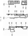
- FIG. 6C is an exploded perspective view of an electronic device according to various embodiments of the present disclosure.
- the electronic device 600 may include a side bezel structure 610 (e.g., the housing), a first support member 611 (e.g., the bracket), a front plate 620, a display 630, a printed circuit board 640, a battery 650, a second support member 660 (e.g., the rear case), an antenna 670, and a rear plate 680.
- the electronic device 600 may omit at least one of the components (e.g., the first support member 611 or the second support member 660) or additionally include other components. At least one of the components of the electronic device 600 may be the same as or similar to at least one of the components of the electronic device 500 of FIG. 6a or 6b , and overlapping descriptions will be omitted below.
- the first support member 611 may be disposed inside the electronic device 600 and connected to the side bezel structure 610 (e.g., the housing), or it may be integrally formed with the side bezel structure 610.
- the first support member 611 may include, for example, the polymer composition of the present disclosure including a metal material and/or a non-metal such as a recycled polyamide, a new polyamide, a glycidyl group-modified ethylene-octene copolymer (EOR-GMA), and an inorganic filler as described above.
- the first support member 611 may support, for example, the display 630 and/or print circuit board 640 against the side bezel structure (e.g., the housing) 610 with one side coupled to the display 630 and the other side coupled to the printed circuit board 640.
- the printed circuit board 640 may be equipped with a processor, memory, and/or interfaces.
- the processor may include, for example, one or more of a central processing unit, an application processor, a graphics processing unit, an image signal processor, a sensor hub processor, or a communication processor.
- the second support member 660 may be a member to prevent collisions and electrical short circuits among the housing 610, the printed circuit board 640, and the battery 650 while supporting and fixing the printed circuit board 640 and the battery 650 in the housing 610 of the electronic device.
- the second support member 660 may include a non-conductive material, for example, the polymer composition according to various embodiments of the present disclosure described above.
- the memory may include, for example, volatile memory or non-volatile memory.
- the interface may include, for example, a high definition multimedia interface (HDMI), a universal serial bus (USB) interface, an SD card interface, and/or an audio interface.
- HDMI high definition multimedia interface
- USB universal serial bus
- the interface may, for example, connect electrically or physically the electronic device 600 to an external electronic device, and it may include a USB connector, an SD card/MMC connector, or an audio connector.
- the battery 650 may include a device for supplying power to at least one component of the electronic device 600 and may include, for example, a non-rechargeable primary battery, a rechargeable secondary battery, or a fuel cell. At least a portion of the battery 650 may be disposed substantially coplanar with the printed circuit board 640, for example. The battery 650 may be integrally disposed inside the electronic device 600 or may be disposed detachably from the electronic device 600.
- the antenna 670 may be disposed between the rear surface plate 680 and the battery 650.
- the antenna 670 may include, for example, a near field communication (NFC) antenna, a wireless charging antenna, and/or a magnetic secure transmission (MST) antenna.
- the antenna 670 may, for example, perform short-range communication with an external device or wirelessly transmit/receive power required for charging.
- an antenna structure may be formed by a part of the side bezel structure 610 and/or the first support member 611 or a combination thereof.
- the housings 510 and 610 of the electronic device may be separated using at least one insulating area 515 to be used as a plurality of antenna radiators.
- the insulating area may be formed by, for example, impregnating the polymer composition of the present disclosure including a recycled polyamide, a new polyamide, a glycidyl group-modified ethylene-octene copolymer (EOR-GMA), and an inorganic filler into a metal material as described above.
- FIG. 6d is a plane view illustrating first support members according to various embodiments of the present disclosure.
- FIG. 6e is a plane view illustrating second support members according to various embodiments of the present disclosure.
- FIG. 6f is a view illustrating a key bracket according to various embodiments of the present disclosure.
- the first support member 611 may include at least one bracket 611a, 611b, 611c, and 611d.
- the brackets 611a, 611b, 611c, and 611d may be a member composed to fix the components (e.g., the display 630, the printed circuit board 640, and the battery 650) of the electronic devices 500 and 600 to the housings 510 and 610.
- the brackets 611a, 611b, 611c, and 611d may include at least one fastening hole 612 for fixing to the housings 510 and 610.
- the brackets 611a, 611b, 611c, and 611d may include at least one lightning hole 613 that improves rigidity and lightens the weight of the brackets 611a, 611b, 611c, and 611d and is formed so that a component of the electronic device 101 may be disposed.
- the second support member 660 may include at least one support plate 660a, 660b, and 660c.
- the support plates 660a, 660b, and 660c may be members for fixing the components of the electronic devices 500 and 600 (e.g., the display 630, the printed circuit board 640, and the battery 650) to the housings 510 and 610.
- the support plates 660a and 660b may include at least one fastening hole 661 for fixing to the housings 510 and 610.
- the support plates 660a, 660b, and 660c may include a lighting hole 662 penetrating through the support plates 660a, 660b, and 660c in the thickness direction and/or a recess 663 formed by partial recessing of the partial area of the support plate 660a, 660b, and 660c, in order to improve rigidity, reduce weight, and secure space for disposal of the electronic device.
- the electronic devices 500 and 600 may include a key bracket 611e.
- the key bracket 611e may be a member for supporting a key (e.g., the key input device 517) inside the housing 510 of the electronic devices 500 and 600.
- the brackets 611a, 611b, 611c, and 611d, the key bracket 611d, and the support plates 660a, 660b, and 660c may include the polymer composition including the above-described recycled polyamide, new polyamide, glycidyl group-modified ethylene-octene copolymer (EOR-GMA), and inorganic filler. Accordingly, plastic waste, particularly marine waste, may be recycled when manufacturing the electronic devices 500 and 600, and mechanical properties, moldability, and appearance quality of the support member 460 manufactured through recycling may be improved.
- EOR-GMA glycidyl group-modified ethylene-octene copolymer
- FIG. 7a is an exploded perspective view of a protective cover and an electronic device mounted thereon according to various embodiments of the present disclosure.
- FIG. 7b is a perspective view of a protective cover on which an electronic device is mounted according to various embodiments of the present disclosure.
- FIG. 7c is a view illustrating a stylus pen cover according to some embodiments of the present disclosure.
- the protective cover 700 may include a first cover 710, a second cover 720, and a connection part 730 connecting the first cover 710 and the second cover 720 integrally.
- the first cover 710 and the second cover 720 may be formed to have substantially the same size.
- the first cover 710 may include a first plate portion 711 and a first side portion 712 extending in a vertical direction from at least a portion of an edge of the first plate portion 711.
- the first side portion 712 may be formed to have a shape corresponding to at least a portion of the side surface 803 of the electronic device 800.
- the second cover 720 may include a second plate portion 721 and a second side portion 722 extending in a vertical direction from at least a portion of an edge of the second plate portion 721.
- the second side portion 722 may also be formed in a shape corresponding to at least a portion of the side surface 803 of the electronic device 800.
- the first side portion 712 and the second side portion 722 may be formed in a curved shape.
- the protective cover 700 may include a cradle 740 attached to the first plate portion 711 of the first cover 710.
- the cradle 740 may include a mounting portion 741 that may accommodate at least a portion of the rear surface 802 and the side surface 803 of the electronic device 800.
- the cradle 740 may be formed of a polymer and/or a metal material.
- the polymer material of cradle 740 may include recycled polyamide.
- the polymer material of the cradle 740 may be a polymer composition of the present disclosure including a recycled polyamide, a new polyamide, a glycidyl group-modified ethylene-octene-based copolymer (EOR-GMA), and an inorganic filler.
- the cradle 740 may be formed of at least one of a metal material, GFRP, CFRP, rubber, silicon, PC, PC-ABS, and PC-FG.
- the cradle 740 may be disposed on the mounting part 741 and include a cradle inner skin layer for protecting the electronic device 800.
- the cradle inner skin layer 780 may be formed of a fabric (e.g., felt).
- the electronic device 800 may include a housing 810 (e.g., the housing structure) including a front surface 801 facing a specified direction, a rear surface 802 facing a direction opposite to the front surface 801, and a side member 811 including the side surface surrounding the space between the front surface 801 and the rear surface 802.
- the electronic device 800 may include a display 830 that is disposed to be visible from the outside through substantially the entire area of the front surface 801.
- the first cover 710 of the protective cover 700 may accommodate at least a portion of the electronic device 800.
- the electronic device 800 may be fixed in such a way that it is mounted on the mounting part 741 of the cradle 740 disposed on the first plate part 711 of the first cover 710.
- the electronic device 800 may be fixed to a protective cover 700 in that the rear surface 802 faces the mounting portion 741 of the cradle 740, and at least a portion of the side surface 803 is tightly fitted to the cradle 740.
- a first state (the state of FIG.
- the notification means 723 may provide a specific notification to the user through a control circuit including an LED indicator built in the interior of the second cover 720.
- the control circuit including the notification means 723 may be wirelessly and/or wiredly connected to the electronic device 800 to receive data and power.
- the protective cover 700 may include a stylus pen cover 750 for accommodating and protecting a stylus pen (not shown).
- the stylus pen cover 750 may be located on the front surface, side surface, or rear surface of the protective cover, and it may be a member that accommodates the stylus pen when the stylus pen is not in use to prevent loss and protects the stylus pen from external impact.
- the stylus pen cover 750 may include the polymer composition of the present disclosure including a recycled polyamide, a new polyamide, a glycidyl group-modified ethylene-octene-based copolymer (EOR-GMA), and an inorganic filler. Accordingly, plastic waste, particularly marine waste, may be recycled when the electronic device 101 is manufactured, and mechanical properties, moldability, and appearance quality of the support member 460 manufactured through recycling may be improved.
- the polymer composition according to various embodiments of the present disclosure may include a recycled polyamide, a new polyamide including at least one polyamide component, a glycidyl group-modified ethylene-octene-based copolymer, and an inorganic filler.
- the recycled polyamide may be material collected from marine plastic waste.
- 10 to 30% by weight of the recycled polyamide, 1 to 50% by weight of the new polyamide, 0.1 to 10% by weight of the glycidyl group-modified ethylene-octene-based copolymer, and 30 to 70% by weight of the inorganic filler may be included.
- the new polyamide may include polyamide PA6 and a modified polyamide having a benzene ring.
- the modified polyamide may include at least one of polyamide PA6I, a copolymer of polyamide PA6I and PA6T, and polyamide MXD6. In some embodiments, 1 to 30% by weight of the polyamide PA6 and 1 to 20% by weight of the modified polyamide may be included.
- the electronic devices 101, 500, and 600 may include the displays 220, 501, and 630 disposed in a first direction; the housings 210, 510, and 610 including an internal space having an opening opened in the first direction; the substrate portion 480 and 640 disposed inside the housing; and the support member 460, 611, and 660 supporting the substrate portion 480 and 640 with respect to the housings 207, 510, and 610 and including a non-conductive material, wherein the support member 460, 611, and 660 may include a polymer composition including a recycled polyamide, a new polyamide including at least one polyamide component, a glycidyl group-modified ethylene-octene-based copolymer, and an inorganic filler.
- the recycled polyamide may be material collected from marine plastic waste.
- the new polyamide may include polyamide PA6 and a modified polyamide having a benzene ring.
- the polymer composition may have a tensile strength of 2300 kgf/cm 2 or more. In some embodiments, the polymer composition may have a notched Izod impact strength of 14 kgf cm/cm or more. In some embodiments, the polymer composition may have a thermal stability with a weight loss of 2.5% or less when heated at 230°C for 30 minutes. In some embodiments, the polymer composition may have a moisture absorption of 1% by weight or less when immersed in water for 24 hours.
- the protective case (e.g., the protective cover 700) according to other embodiments of the present disclosure may include a polymer composition including a recycled polyamide, a new polyamide including at least one polyamide component, glycidyl group-modified ethylene-octene-based copolymer, and an inorganic filler as a protective case that is disposed adjacent to at least a portion of an external surface of an electronic device to protect the electronic device from external impact.
- the recycled polyamide may include material collected from marine plastic waste.
Landscapes
- Chemical & Material Sciences (AREA)
- Engineering & Computer Science (AREA)
- Health & Medical Sciences (AREA)
- Chemical Kinetics & Catalysis (AREA)
- Medicinal Chemistry (AREA)
- Polymers & Plastics (AREA)
- Organic Chemistry (AREA)
- Computer Hardware Design (AREA)
- Theoretical Computer Science (AREA)
- General Engineering & Computer Science (AREA)
- Physics & Mathematics (AREA)
- Human Computer Interaction (AREA)
- General Physics & Mathematics (AREA)
- General Chemical & Material Sciences (AREA)
- Life Sciences & Earth Sciences (AREA)
- Sustainable Development (AREA)
- Compositions Of Macromolecular Compounds (AREA)
- Casings For Electric Apparatus (AREA)
Applications Claiming Priority (2)
| Application Number | Priority Date | Filing Date | Title |
|---|---|---|---|
| KR1020220016468A KR20230120001A (ko) | 2022-02-08 | 2022-02-08 | 재생 폴리아미드를 포함하는 폴리머 조성물 및 이를 포함하는 전자 장치 및 전자 장치 보호 케이스 |
| PCT/KR2023/001771 WO2023153775A1 (ko) | 2022-02-08 | 2023-02-08 | 재생 폴리아미드를 포함하는 폴리머 조성물 및 이를 포함하는 전자 장치 및 전자 장치 보호 케이스 |
Publications (2)
| Publication Number | Publication Date |
|---|---|
| EP4407004A1 true EP4407004A1 (de) | 2024-07-31 |
| EP4407004A4 EP4407004A4 (de) | 2025-03-19 |
Family
ID=87521679
Family Applications (1)
| Application Number | Title | Priority Date | Filing Date |
|---|---|---|---|
| EP23753123.1A Pending EP4407004A4 (de) | 2022-02-08 | 2023-02-08 | Polymerzusammensetzung mit recyceltem polyamid und elektronische vorrichtung und schutzgehäuse für elektronische vorrichtung damit |
Country Status (2)
| Country | Link |
|---|---|
| US (1) | US20230250280A1 (de) |
| EP (1) | EP4407004A4 (de) |
Family Cites Families (3)
| Publication number | Priority date | Publication date | Assignee | Title |
|---|---|---|---|---|
| EP0604367B1 (de) * | 1992-12-22 | 1997-01-29 | Ciba SC Holding AG | Molekulargewichtserhöhung von Polyamiden |
| US9109114B2 (en) * | 2012-09-27 | 2015-08-18 | E I Du Pont De Nemours And Company | Polyamides having improved anti-delamination |
| FR3110585B1 (fr) * | 2020-05-19 | 2025-01-17 | Arkema France | Structure multicouche a base de polyamide recycle |
-
2023
- 2023-02-08 EP EP23753123.1A patent/EP4407004A4/de active Pending
- 2023-03-07 US US18/118,453 patent/US20230250280A1/en active Pending
Also Published As
| Publication number | Publication date |
|---|---|
| US20230250280A1 (en) | 2023-08-10 |
| EP4407004A4 (de) | 2025-03-19 |
Similar Documents
| Publication | Publication Date | Title |
|---|---|---|
| KR20230120001A (ko) | 재생 폴리아미드를 포함하는 폴리머 조성물 및 이를 포함하는 전자 장치 및 전자 장치 보호 케이스 | |
| CN111825977B (zh) | 增强热塑性模塑组合物 | |
| US8859665B2 (en) | Polyamide housings for portable electronic devices | |
| CN103946272B (zh) | 聚酰胺模塑材料、其用途,以及由其制备的模制部件 | |
| KR102318934B1 (ko) | 강화 폴리아미드 몰딩 조성물 및 이로부터 생산된 인젝션 몰딩 | |
| US20150273795A1 (en) | Metal resin composite body and manufacturing method of metal resin composite body | |
| EP2727951A1 (de) | Mobile elektronische Vorrichtungen aus amorphen Polyamiden | |
| KR101323507B1 (ko) | 난연성 폴리아마이드 조성물 | |
| CN106479171A (zh) | 聚酰胺模塑材料及可由其制得的模塑制品 | |
| US20150283793A1 (en) | Metal resin composite body and manufacturing method of metal resin composite body | |
| HK1221239A1 (zh) | 用於移动电子装置的填充聚合物组合物 | |
| WO2011078492A2 (ko) | 다기능성 수지 복합재 및 이를 이용한 성형품 | |
| US10174199B2 (en) | Resin composition | |
| US20220089860A1 (en) | High stiff thermoplastic compositions for thin-wall structures | |
| KR20190129915A (ko) | 편광판 및 화상 표시 장치 | |
| KR101783505B1 (ko) | 향상된 표면 특성 및 내충격성을 갖는 전방향족 액정 폴리에스테르 수지 컴파운드 | |
| EP4407004A1 (de) | Polymerzusammensetzung mit recyceltem polyamid und elektronische vorrichtung und schutzgehäuse für elektronische vorrichtung damit | |
| EP2767555A1 (de) | Mobile elektronische Vorrichtungen aus amorphen Polyamiden | |
| US20230203302A1 (en) | Thermoplastic Resin Composition and Article Produced Therefrom | |
| JP5748491B2 (ja) | 気密電子部品の製造方法、及び気密電子部品 | |
| KR101225902B1 (ko) | 디스플레이의 전면 테두리와 일체형으로 형성되는 전면 보호 패널 및 이를 포함하는 tv | |
| US20250329837A1 (en) | Electronic device housing having recycled polymer, and electronic device comprising same | |
| KR101709375B1 (ko) | 실란계 화합물, 이의 제조방법 및 이를 포함하는 폴리카보네이트 수지 조성물 | |
| EP4298164A1 (de) | Polyamidzusammensetzungen mit funktionalisiertem polyolefin und mobile elektronische vorrichtungskomponenten damit | |
| CN210958546U (zh) | 一种直下式窄边框平板电视机模组 |
Legal Events
| Date | Code | Title | Description |
|---|---|---|---|
| STAA | Information on the status of an ep patent application or granted ep patent |
Free format text: STATUS: THE INTERNATIONAL PUBLICATION HAS BEEN MADE |
|
| PUAI | Public reference made under article 153(3) epc to a published international application that has entered the european phase |
Free format text: ORIGINAL CODE: 0009012 |
|
| STAA | Information on the status of an ep patent application or granted ep patent |
Free format text: STATUS: REQUEST FOR EXAMINATION WAS MADE |
|
| 17P | Request for examination filed |
Effective date: 20240424 |
|
| AK | Designated contracting states |
Kind code of ref document: A1 Designated state(s): AL AT BE BG CH CY CZ DE DK EE ES FI FR GB GR HR HU IE IS IT LI LT LU LV MC ME MK MT NL NO PL PT RO RS SE SI SK SM TR |
|
| A4 | Supplementary search report drawn up and despatched |
Effective date: 20250217 |
|
| RIC1 | Information provided on ipc code assigned before grant |
Ipc: C08J 11/06 20060101ALI20250211BHEP Ipc: C08L 23/26 20060101ALI20250211BHEP Ipc: C08L 77/02 20060101ALI20250211BHEP Ipc: C08L 77/00 20060101AFI20250211BHEP |
|
| DAV | Request for validation of the european patent (deleted) | ||
| DAX | Request for extension of the european patent (deleted) |