EP4406668B1 - Inspektions- und sortiervorrichtung - Google Patents
Inspektions- und sortiervorrichtung Download PDFInfo
- Publication number
- EP4406668B1 EP4406668B1 EP23153953.7A EP23153953A EP4406668B1 EP 4406668 B1 EP4406668 B1 EP 4406668B1 EP 23153953 A EP23153953 A EP 23153953A EP 4406668 B1 EP4406668 B1 EP 4406668B1
- Authority
- EP
- European Patent Office
- Prior art keywords
- sorting
- cover
- zone
- inspection
- transport
- Prior art date
- Legal status (The legal status is an assumption and is not a legal conclusion. Google has not performed a legal analysis and makes no representation as to the accuracy of the status listed.)
- Active
Links
Images


Classifications
-
- B—PERFORMING OPERATIONS; TRANSPORTING
- B07—SEPARATING SOLIDS FROM SOLIDS; SORTING
- B07C—POSTAL SORTING; SORTING INDIVIDUAL ARTICLES, OR BULK MATERIAL FIT TO BE SORTED PIECE-MEAL, e.g. BY PICKING
- B07C5/00—Sorting according to a characteristic or feature of the articles or material being sorted, e.g. by control effected by devices which detect or measure such characteristic or feature; Sorting by manually actuated devices, e.g. switches
- B07C5/34—Sorting according to other particular properties
- B07C5/3416—Sorting according to other particular properties according to radiation transmissivity, e.g. for light, x-rays, particle radiation
-
- B—PERFORMING OPERATIONS; TRANSPORTING
- B07—SEPARATING SOLIDS FROM SOLIDS; SORTING
- B07C—POSTAL SORTING; SORTING INDIVIDUAL ARTICLES, OR BULK MATERIAL FIT TO BE SORTED PIECE-MEAL, e.g. BY PICKING
- B07C5/00—Sorting according to a characteristic or feature of the articles or material being sorted, e.g. by control effected by devices which detect or measure such characteristic or feature; Sorting by manually actuated devices, e.g. switches
- B07C5/36—Sorting apparatus characterised by the means used for distribution
-
- B—PERFORMING OPERATIONS; TRANSPORTING
- B07—SEPARATING SOLIDS FROM SOLIDS; SORTING
- B07C—POSTAL SORTING; SORTING INDIVIDUAL ARTICLES, OR BULK MATERIAL FIT TO BE SORTED PIECE-MEAL, e.g. BY PICKING
- B07C5/00—Sorting according to a characteristic or feature of the articles or material being sorted, e.g. by control effected by devices which detect or measure such characteristic or feature; Sorting by manually actuated devices, e.g. switches
- B07C5/36—Sorting apparatus characterised by the means used for distribution
- B07C5/38—Collecting or arranging articles in groups
-
- B—PERFORMING OPERATIONS; TRANSPORTING
- B07—SEPARATING SOLIDS FROM SOLIDS; SORTING
- B07C—POSTAL SORTING; SORTING INDIVIDUAL ARTICLES, OR BULK MATERIAL FIT TO BE SORTED PIECE-MEAL, e.g. BY PICKING
- B07C5/00—Sorting according to a characteristic or feature of the articles or material being sorted, e.g. by control effected by devices which detect or measure such characteristic or feature; Sorting by manually actuated devices, e.g. switches
- B07C5/34—Sorting according to other particular properties
- B07C5/342—Sorting according to other particular properties according to optical properties, e.g. colour
- B07C5/3425—Sorting according to other particular properties according to optical properties, e.g. colour of granular material, e.g. ore particles, grain
- B07C5/3427—Sorting according to other particular properties according to optical properties, e.g. colour of granular material, e.g. ore particles, grain by changing or intensifying the optical properties prior to scanning, e.g. by inducing fluorescence under UV or x-radiation, subjecting the material to a chemical reaction
-
- B—PERFORMING OPERATIONS; TRANSPORTING
- B07—SEPARATING SOLIDS FROM SOLIDS; SORTING
- B07C—POSTAL SORTING; SORTING INDIVIDUAL ARTICLES, OR BULK MATERIAL FIT TO BE SORTED PIECE-MEAL, e.g. BY PICKING
- B07C5/00—Sorting according to a characteristic or feature of the articles or material being sorted, e.g. by control effected by devices which detect or measure such characteristic or feature; Sorting by manually actuated devices, e.g. switches
- B07C5/36—Sorting apparatus characterised by the means used for distribution
- B07C5/363—Sorting apparatus characterised by the means used for distribution by means of air
- B07C5/365—Sorting apparatus characterised by the means used for distribution by means of air using a single separation means
Definitions
- the invention is related to inspection and sorting apparatus, in particular to inspection and sorting apparatus comprising a support frame supporting a transport mechanism with an endless transport belt extending along an inspection zone in which items transported on the transport belt along a transport path are inspected by an inspection mechanism and along a sorting zone in which items to be rejected are sorted out by being moved, by a sorting mechanism, out of the transport path in a direction transverse to the transport path to a sorting side, wherein, in an operation state of the apparatus, a space lateral to and alongside the sorting zone, into which the rejected items are moved, is covered by a housing cover but is open to the sorting zone and to the downside to allow the rejected items to further fall or slide down by gravity and/or the apparatus is provided with a side cover covering a region below the sorting zone laterally from the sorting side.
- Inspection and sorting is among other a task arising in f.i. inspection of food products or pharmaceutical products in terms of checking them whether they are in compliance with given conditions, to avoid foreign material or other, as well-known by the person skilled in the art.
- X-ray inspection and sorting systems are often implemented as modular units, with a separated isolated X-ray inspection system module which itself, has no sorting mechanism and can be inserted into a processing line in which a sorting unit is provided further downstream.
- a sorting unit is provided further downstream.
- non-modular systems in which inspection and sorting is done within one device, having its endless transport belt extending along both inspection zone and sorting zone.
- Such a system is f.i. disclosed in document WO 2009/112852 A1 , where a continuous belt passes an inspection point and a reject point, and a bin is arranged sidewise at the level of the reject point to accommodate rejected items.
- This document is further related to a test sample adapted to challenge the measuring and/or monitoring equipment of such device, in form of a laminated card with foreign body test pieces and ID-zones.
- EP 3 486 640 A1 a radiation scanner system and sorting system is disclosed, where a separation gap is provided between a reject bin top and a reject bin bottom.
- the separation gap allows to pass the transport section of the conveyor belt therethrough while the slack return section of the conveyor belt loop is passed around the reject bin bottom.
- US 2002/0060174 A1 discloses a specific nozzle arrangement with covers for regulating a flow of air to be blown from a nozzle to an article such that the article can be reliably sorted out by said air blow.
- a sorting cover for discharged articles is arranged in an oblique manner.
- the invention seeks to improve an inspection and sorting apparatus as initially introduced, that is where inspection and sorting takes place along one and the same endless transport belt, such as disclosed in WO 2009/112852 A1 , aiming at a combination of reliably, safe use and easy handling of the apparatus when not in use.
- the invention is defined by an inspection and sorting apparatus according to independent claim 1, providing a further development of an inspection and sorting apparatus of the kind as initially introduced, which is essentially characterized in that the housing cover and/or the side cover is movable between its/their covering position in the operation/working state of the apparatus and a release position granting lateral access to the sorting zone and/or to said region from the sorting side.
- the entire transport belt is, after access being provided by having the housing cover/side cover in their release position, removable along a removal path on a height level above the housing cover in its release position.
- the housing cover and the side cover are connected and their motion between covering and release position is linked. Thereby, access to sorting zone and below for belt removal access in the part related to the sorting zone is provided by one motion/operation for the operator only.
- the motion between covering position and release position is uniform as seen along the direction of the transport path. Moreover, it is preferred that the motion between covering and release position is a pivot motion.
- a close/release means is provided to block/allow the pivot motion from the covering position into the release position.
- Said opening/release means firmly secure the respective cover in its/their covering position when the apparatus is operated.
- the pivot axis of the pivot motion has a predominant component of direction along the transport path.
- the pivot axis is in a horizontal plane and preferably arranged in transport direction.
- the housing cover/side cover does, during the pivot motion, not extend beyond its furthermost end part in its covering position, seen in transport direction. This allows full integrability of the apparatus into a processing line, without any additional exit zone length of the transport path.
- a strap formed by the transport path of and return path below the sorting zone is accessible. That is, not only access to the sorting zone above the transport belt maybe granted, but also the access for easier transport belt removal/exchange.
- the inspection zone, a further region below the inspection zone, an inlet zone along which the transport belt is extended upstream the transport path of the inspection zone, and/or an again further region below the inlet zone is laterally covered by a further side cover arrangement in its covering position in the working state, and is movable, in particular pivotable, in particular about a pivot axis parallel to or colinear with the pivot axis of the housing cover and/or the side cover, as a whole or in two or more pieces.
- the cover for the inspection zone can have a first opening angle, preferably to end up in a horizontal surface. Said horizontal surface could even be used for the operator as a desk when in its release position.
- the covering panels on the side of the inlet zone and the sorting zone can provide for opening angles beyond 90°, in particular beyond 120°, further preferred beyond 145°. Thereby, operation personal can approach the transport belt at the inlet zone and the sorting zone even closer.
- a shielding curtain is provided, such shielding curtain could be configured as vertically switch sheets of f.i. rubber or of a rubber-like material containing a radition/blocking component such as lead oxide or tungsten, for example as a sandwiched laminate or in distributed form.
- An entire shielding curtain can consist of a single sheet, but also more sheets such as a carpet pair of sheets can be used with the slits of one sheet offset against the slits of the other, so as to minimize the radiation leakage through the curtain.
- a bin is provided, the bin being positionable below said space in working position, for accommodating rejected items falling down/through said space.
- bin configurations are thought of to accommodate the rejected items, beginning from a simple bin placed below the (opening) bottom of the housing cover.
- the bin may have roller to be rolled for transport.
- the bin may be positioned in a hanging arrangement within the housing cover.
- the bin is releasably mounted to the side cover and/or housing cover and the motion of the housing is in particular effectable in the mounting position of the bin.
- the cover housing can be just pivoted with the bin still in its mounted place.
- at least a part of the front cover of the housing cover can be opened such as to release the bin for motion, f.i. sliding motion out of the position in/beyond the housing cover.
- movability of the bin is blocked by said at least openable portion of the front cover.
- an inner cover laterally covering a space between transport path side and return path side of the transport belt and dimensioned to pass through the interior of the endless belt when the endless belt is relatively moved with respect to the inner cover transverse to the transport direction.
- the apparatus is comprising a support/carrier beam, extending in particular in transport path direction, to which a hinge mechanism for the pivoting motion of the housing cover, the side cover, and/or the further cover are mounted, said carrier being in particular arranged on a height level below the inner cover and below the return path of the transport belt.
- Said support beam can, in particular being made of one piece, which is preferred.
- a/the hinge mechanism position for said pivoting motion of housing cover, side cover, and/or further side cover is with a vertical distance from the height level of the return path of the transport belt of more than 1 cm, preferably more than 2 cm, in particular more than 3 cm, and/or lower than 16 cm, preferably lower than 12 cm, in particular lower than 8 cm. This gives a preferred dimensional interplay regarding positioning of the cover panels/cover housing in their release position, space for lateral removal of the transport belt and overall dimension of side cover panels/housing cover.
- the transport belt is driven in known manner by a drive mechanism including a drive motor.
- a drive motor can be arranged adjacent and below of a driven end roller at the sorting-side end of the transport path.
- a holding mechanism holding a roller at the begin and/or a roller at the end of the transport path of the transport belt is switchable from a holding position for the working state of the apparatus and a release position allowing to strip off the belt for its lateral removal.
- one of said roller can be moved from its position in the working/operating state of the apparatus into a tension release position such that the transport belt can be removed with reduced/even without tension of the belt.
- two holding arms are arranged pivotable about an axis orthogonal to transport direction and to gravity, said arms holding the roller at their free end.
- the apparatus may have several safety means, f.i. an electrical interlock between the X-ray generator of the inspection mechanism and those movable cover elements (panels, housing), whereby power to the X-ray generator is automatically cut off when one of these movable covering elements is not in their covering position of the working/operating state of the apparatus.
- safety means f.i. an electrical interlock between the X-ray generator of the inspection mechanism and those movable cover elements (panels, housing), whereby power to the X-ray generator is automatically cut off when one of these movable covering elements is not in their covering position of the working/operating state of the apparatus.
- the apparatus comprises an operating panel, said operating panel being preferably to the side of the sorting side.
- Such operator panel can be provided with several operating functions, including also an input means, f.i. in form of a touchscreen, even multitouch-screen, and/or an emergency stop button.
- the operator's side preferably coincides with the sorting side, that is sorting is to the lateral side where the operation panel is arranged. This gives more versatility for the inserting of the apparatus into a processing line.
- the advantages provided by the arrangement of the housing cover/bin is preferably for an inspection mechanism requiring highest level of shielding, such as radiation scanner systems, in particular X-ray scanner. However, it is also beneficial for other kind of inspection, such as optical inspection, and even weight inspection by having a weighing unit at weighing zone as inspection zone.
- the preferred inspection mechanism consists of or comprises radiation scanning technique, in particular X-ray inspection technique.
- a frame part can be used instead of the shielding housing cover and/or side cover.
- the arrangement of the housing cover/bin for granting better access is also independent of the particular technique of the sorting mechanism, any kind of sorting mechanism used in the art can be used here, including pushing by mechanical pushing or air blast, bifurcation elements pivoted/moved into the transport path to deflect a rejected item, or other.
- a control of the apparatus equipped with evaluation software giving, in real time immediate result of inspection so as to generate a signal indicative of whether an item is to be rejected, said signal being received timely by a actuator of the sorting mechanism to provide for a rejection action at the time the rejected item passes the appropriate rejection point in the sorting zone, as generally known in the art.
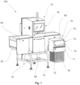
- An inspection and sorting apparatus 100 as shown in Fig. 1 comprises a support frame 10 standing on height-adjustable feet 12. Supported by support frame 10 is a transport mechanism comprising an endless conveyor belt 20. The upper side of conveyor belt 20 defines a transport plane and a transport path, along which items to be inspected and sorted (not shown) are transported, in Fig. 1 from the left to the right. Roughly centered with reference to the extension of the transport belt 20 is an inspection unit 15.
- inspection unit 15 is an X-ray inspection unit, as such known to the person skilled in the art and, therefore, not further described here regarding inspection aspects.
- Items to be inspected and sorted enter the apparatus 100 by passing a first (shielding) curtain 31 ( Fig. 2 ) to enter an inlet zone 30 as starting section of the transport path, covered to the front side by a first cover panel 83. Further downstream in transport direction the items pass a second curtain 34 to enter an inspection zone 40 ( Fig. 2 ) which is covered by second cover panel 84, where the items are X-ray inspected by inspection unit 15. After inspection, the items pass a third curtain 45 to reach a sorting zone 50 ( Fig. 2 ). Those items successfully passing the X-ray inspection are then leaving the apparatus 100 by passing a fourth curtain 51, to be then handed over to subsequent processing f.i. to another transport belt.
- Those items not successfully passing the X-ray inspection are sorted out by a not-shown sorting mechanism, which in the shown embodiment is implemented by air-blasting.
- the function of the sorting mechanism is to deflect the rejected items out of the transport path, such that they do not leave the sorting zone 50 in transport direction, but are deflected to a sorting side, in Fig. 1 , 2 to the front side (respectively right side when viewed in transport direction).
- the rejected items are thus moved through an opening 65 in a third panel 60 laterally covering (with exception of opening 65) the sorting zone 50. Thereby, the rejected items enter the space beside the sorting zone 50, which is covered by housing cover 70.
- housing cover 70 has a top cover 75, lateral covers 72 and 73, and towards the sorting side a front cover with a first upper portion 74 and a lower second portion 71, which is hinged to be pivotable such that a bin 76, which in this embodiment is configured as hanging in housing cover 70, can be removed to be emptied and re-inserted.
- an operation panel 18 of inspection unit 15 is facing also to the sorting side, that is the apparatus 100 has a front side being the operating side and the sorting of rejected items being also versus the operating side (which is the sorting side).
- first cover panel 83 In the working state/configuration, the apparatus is nearly fully covered to avoid stray X-rays coming out of the apparatus, in a way as the person skilled in the art is used to.
- said coverage is achieved by first cover panel 83, second cover panel 84, and third cover panel 60 to which housing cover 70 is fixedly attached.
- housing cover 70 housing its interior (which is the space into which the rejected items are moved to then fall down by gravity into bin 76) is mounted to the apparatus 100 laterally covering the sorting zone 50, access to sorting zone 50 can be obtained without dismounting the housing cover 70. This is because housing cover 70 can be pivoted from its working position in the working state shown in Fig. 1 to a pivoted release position shown in Fig. 2 , giving said lateral access.
- support frame 10 supports a longitudinal carrier beam 80 which extends in transport direction, in this embodiment along insert zone 30, inspection zone 40 and sorting zone 50.
- a hinge mechanism 67a is provided, hingedly linking the carrier beam 80 to a lower portion 67 of the third cover panel 60. Since the carrier beam 80 is in a height direction, arranged below the level of the lower side of the transport belt 20 (defining the return path thereof), said lower portion 67a extending to about the transport plane is a side cover covering a region below the sorting zone laterally from the sorting side.
- a hinge arrangement 84a is provided at level (in transport direction) of the inspection zone 40, hingedly linking the second cover panel 84, and further, at level of the inlet zone 30, a hinge mechanism 83a hingedly linking first cover panel 83.
- a hinge arrangement 84a is provided at level (in transport direction) of the inspection zone 40, hingedly linking the second cover panel 84, and further, at level of the inlet zone 30, a hinge mechanism 83a hingedly linking first cover panel 83.
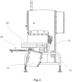
- the cover housing 70 for coupling the reject bin 76 to the apparatus 100 in a covered manner is not even to be dismounted for belt removal/replacement. This is best to be seen from Fig. 3 and Fig. 4 .
- the belt 20 can be taken off uniformly with essentially unchanged area of the interior of the endless belt 20 orthogonal to a width direction (which width direction being orthogonal to both transport direction and height direction).
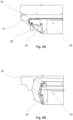
- roller 21 is pivotable via pivotable holding arms 24 in, with reference to Fig. 2 , counter clockwise direction.
- a release lever 26 is activated to allow motion from the working position of arms 24 shown in Fig. 5A to be rotated in the position shown in Fig. 5B to reduce the tension of the belt 20.
- Said lever 26 can be activated tool-free just by hand.
- the pivot motion to bring the housing cover 70 from its working state to a release state can be executed even without removing bin 76 from the housing cover 70. Then ( Fig. 2 ), the release position of the housing cover 70 is roughly such that the plane of third cover panel 60 is essentially horizontal. In case that bin 76 is removed before pivoting housing cover 70, the pivot motion can continue significantly beyond 90°, such as to provide for more lateral space at the level of the sorting zone 50, if desired. As can be further seen in Fig. 3 , coupling of the bin 76 for hanging arrangement can also be modified for a bin standing on the floor, as bin 78 shown in Fig. 3 , having roller feet 78a.
- Bin 78 can be emptied f.i. by opening its front door, and has a first portion being in its working position underneath the housing cover 70. Bin 78 further has a second portion 78b which, seen in direction of gravity, is arranged below the sorting zone 50 or a part thereof.
- the first cover panel 83 and the support frame 10 do not overlap in transport direction. Also there is no overlap between the support frame 10 and the housing cover 70 in transport direction, while the support frame laterally extends in width direction beyond the inspection zone 40.
- protection panel 90 The space between upper side (transport) and lower side (return path) of the transport belt 20 is protected by protection panel 90 even in the release position of cover panels 83, 84 and of housing cover 70.
- Respective sections 93, 94 and 95 of protection panel 90 corresponding to the zones 30, 40, 50 are continuous in this embodiment, but could be in form of several independent pieces.
Landscapes
- Health & Medical Sciences (AREA)
- General Health & Medical Sciences (AREA)
- Toxicology (AREA)
- Sorting Of Articles (AREA)
- Discharge Of Articles From Conveyors (AREA)
Claims (15)
- Inspektions- und Sortiervorrichtung (100), umfassend einen Tragrahmen (10), der einen Transportmechanismus mit einem endlosen Transportband (20) trägt, das sich entlang einer Inspektionszone (40) erstreckt, in der Gegenstände, die auf dem Transportband entlang einer Transportbahn transportiert werden, durch einen Inspektionsmechanismus (15) inspiziert werden und entlang einer Sortierzone (50), in der zu verwerfende Gegenstände durch Bewegen, durch einen Sortiermechanismus, aus der Transportbahn in einer Richtung quer zu der Transportbahn zu einer Sortierseite aussortiert werden, wobei in einem Betriebszustand der Vorrichtung,ein seitlich und entlang der Sortierzone (50) angeordneter Raum, in den die verworfenen Gegenstände hinein bewegt werden, durch eine Gehäuseabdeckung (70) abgedeckt ist, jedoch zur Sortierzone und nach unten hin offen ist, um ein weiteres Herabfallen oder Herabrutschen der verworfenen Gegenstände durch Schwerkraft zu ermöglichen, und/oderdie Vorrichtung mit einer Seitenabdeckung (67) bereitgestellt ist, die einen Bereich unterhalb der Sortierzone (50) seitlich von der Sortierseite abdeckt,dadurch gekennzeichnet, dass die Gehäuseabdeckung (70) und/oder die Seitenabdeckung (67) der Vorrichtung zwischen ihrer Abdeckposition im Betriebszustand und einer Freigabeposition, die einen seitlichen Zugang zu der Sortierzone (50) und/oder zu diesem Bereich von der Sortierseite her ermöglicht, bewegbar ist/sind.
- Vorrichtung nach Anspruch 1, wobei die Gehäuseabdeckung (70) und die Seitenabdeckung (67) miteinander verbunden sind und ihre Bewegung zwischen Abdeck- und Freigabeposition verknüpft ist.
- Vorrichtung nach Anspruch 1 oder 2, wobei die Bewegung zwischen Abdeckposition und Freigabeposition entlang der Richtung der Transportbahn gesehen gleichförmig ist.
- Vorrichtung nach einem der vorhergehenden Ansprüche, wobei die Bewegung zwischen Abdeck- und Freigabeposition eine Schwenkbewegung ist.
- Vorrichtung nach Anspruch 4, wobei die Schwenkachse der Schwenkbewegung eine überwiegende Richtungskomponente entlang der Transportbahn aufweist.
- Vorrichtung nach einem der vorhergehenden Ansprüche, wobei in der Freigabeposition der Seitenabdeckung (67) ein Band, das durch die Transportbahn und die Rückführbahn unterhalb der Sortierzone gebildet wird, zugänglich ist.
- Vorrichtung nach einem der vorhergehenden Ansprüche, wobei die Inspektionszone, ein weiterer Bereich unterhalb der Inspektionszone, eine Einlaufzone, entlang welcher sich das Transportband stromaufwärts der Transportbahn der Inspektionszone erstreckt, und/oder ein wiederum weiterer Bereich unterhalb der Einlaufzone seitlich durch eine weitere Seitenabdeckanordnung (84, 83) in ihrer Abdeckposition im Betriebszustand abgedeckt ist und als Ganzes oder in zwei oder mehreren Teilen insbesondere um eine Schwenkachse parallel oder kollinear zu der Schwenkachse der Gehäuseabdeckung (70) und/oder der Seitenabdeckung (67) beweglich, insbesondere schwenkbar ist.
- Vorrichtung nach einem der vorhergehenden Ansprüche, umfassend einen Behälter (76; 78), der unterhalb des Raums in einer Arbeitsposition positionierbar ist, um verworfene Gegenstände, die nach unten/durch den Raum fallen, aufzunehmen.
- Vorrichtung nach Anspruch 8, wobei der Behälter lösbar an der Seitenabdeckung und/oder der Gehäuseabdeckung montiert ist und die Bewegung des Gehäuses insbesondere in der Montageposition des Behälters (76) ausführbar ist.
- Vorrichtung nach einem der vorhergehenden Ansprüche, aufweisend eine innere Abdeckung (90), die einen Raum zwischen Transportbahnseite und Rückführbahnseite des Transportbands seitlich abdeckt und so dimensioniert ist, dass sie durch das Innere des endlosen Bands hindurchgeht, wenn das endlose Band relativ zu der inneren Abdeckung (90) quer zu der Transportrichtung bewegt wird.
- Vorrichtung nach Anspruch 4 bis 10, umfassend einen Trägerbalken (80), der sich insbesondere in Transportbahnrichtung erstreckt und an dem ein Scharniermechanismus (67a; 84a, 83a) für die Schwenkbewegung der Gehäuseabdeckung, der Seitenabdeckung und/oder der weiteren Abdeckung angebracht ist, wobei der Trägerbalken insbesondere auf einem Höhenniveau unterhalb der inneren Abdeckung und unterhalb der Rückführbahn des Transportbands angeordnet ist.
- Vorrichtung nach Anspruch 4 bis 11, wobei eine/die Position des Scharniermechanismus (67a, 83a, 84a) für die Schwenkbewegung der Gehäuseabdeckung (70), der Seitenabdeckung (67) und/oder der weiteren Seitenabdeckung (84, 83) einen vertikalen Abstand von dem Höhenniveau der Rückführbahn des Transportbands von mehr als 1 cm, vorzugsweise mehr als 2 cm, insbesondere mehr als 3 cm, und/oder weniger als 16 cm, vorzugsweise weniger als 12 cm, insbesondere weniger als 8 cm aufweist.
- Vorrichtung nach einem der vorhergehenden Ansprüche, wobei ein Haltemechanismus (24), der eine Rolle (21) am Anfang und/oder eine Rolle am Ende der Transportbahn des Transportbands hält, aus einer Halteposition für den Betriebszustand der Vorrichtung und einer Freigabeposition, die es ermöglicht, das Band für seine seitliche Entnahme abzustreifen, umschaltbar ist.
- Vorrichtung nach einem der vorhergehenden Ansprüche, umfassend ein Bedienfeld (18), wobei das Bedienfeld vorzugsweise auf der Seite der Sortierseite angeordnet ist.
- Vorrichtung nach einem der vorhergehenden Ansprüche, wobei der Inspektionsmechanismus (15) aus einer Röntgeninspektion der durch die Vorrichtung verarbeiteten Gegenstände besteht oder diese umfasst.
Priority Applications (7)
| Application Number | Priority Date | Filing Date | Title |
|---|---|---|---|
| ES23153953T ES3033321T3 (en) | 2023-01-30 | 2023-01-30 | Inspection and sorting apparatus |
| EP23153953.7A EP4406668B1 (de) | 2023-01-30 | 2023-01-30 | Inspektions- und sortiervorrichtung |
| AU2023270220A AU2023270220A1 (en) | 2023-01-30 | 2023-11-21 | Inspection and sorting apparatus |
| US18/390,984 US12138664B2 (en) | 2023-01-30 | 2023-12-20 | Inspection and sorting apparatus |
| CN202311794548.3A CN118403805A (zh) | 2023-01-30 | 2023-12-25 | 检查和分拣设备 |
| JP2024009461A JP2024108147A (ja) | 2023-01-30 | 2024-01-25 | 検査選別装置 |
| CA3227637A CA3227637A1 (en) | 2023-01-30 | 2024-01-29 | Inspection and sorting apparatus |
Applications Claiming Priority (1)
| Application Number | Priority Date | Filing Date | Title |
|---|---|---|---|
| EP23153953.7A EP4406668B1 (de) | 2023-01-30 | 2023-01-30 | Inspektions- und sortiervorrichtung |
Publications (2)
| Publication Number | Publication Date |
|---|---|
| EP4406668A1 EP4406668A1 (de) | 2024-07-31 |
| EP4406668B1 true EP4406668B1 (de) | 2025-04-30 |
Family
ID=85150301
Family Applications (1)
| Application Number | Title | Priority Date | Filing Date |
|---|---|---|---|
| EP23153953.7A Active EP4406668B1 (de) | 2023-01-30 | 2023-01-30 | Inspektions- und sortiervorrichtung |
Country Status (7)
| Country | Link |
|---|---|
| US (1) | US12138664B2 (de) |
| EP (1) | EP4406668B1 (de) |
| JP (1) | JP2024108147A (de) |
| CN (1) | CN118403805A (de) |
| AU (1) | AU2023270220A1 (de) |
| CA (1) | CA3227637A1 (de) |
| ES (1) | ES3033321T3 (de) |
Family Cites Families (8)
| Publication number | Priority date | Publication date | Assignee | Title |
|---|---|---|---|---|
| JP2002153822A (ja) | 2000-11-20 | 2002-05-28 | Ishida Co Ltd | 振分装置及びそれを用いた品質検査機器 |
| US20060237349A1 (en) * | 2005-04-21 | 2006-10-26 | Solomon Michael T | Secure collection of rejected articles |
| GB0804764D0 (en) | 2008-03-14 | 2008-04-16 | Cheyney Design & Dev Ltd | Test apparatus |
| JP6487649B2 (ja) * | 2014-08-08 | 2019-03-20 | 株式会社イシダ | 検査振分システム |
| EP3486640B1 (de) | 2017-11-17 | 2020-06-03 | Mettler-Toledo, LLC | Röntgeninspektionssystem mit aussortierbehälter |
| EP3520911B1 (de) * | 2018-02-01 | 2021-07-07 | Mettler-Toledo Safeline Limited | Sammelbehälter für ein inline-produktinspektionssystem und inline-produktinspektionssystem |
| JP7151089B2 (ja) | 2018-02-06 | 2022-10-12 | 株式会社サタケ | 光学式選別機 |
| GB2591510A (en) * | 2020-01-31 | 2021-08-04 | Ishida Europe Ltd | Food product quality control system |
-
2023
- 2023-01-30 EP EP23153953.7A patent/EP4406668B1/de active Active
- 2023-01-30 ES ES23153953T patent/ES3033321T3/es active Active
- 2023-11-21 AU AU2023270220A patent/AU2023270220A1/en active Pending
- 2023-12-20 US US18/390,984 patent/US12138664B2/en active Active
- 2023-12-25 CN CN202311794548.3A patent/CN118403805A/zh active Pending
-
2024
- 2024-01-25 JP JP2024009461A patent/JP2024108147A/ja active Pending
- 2024-01-29 CA CA3227637A patent/CA3227637A1/en active Pending
Also Published As
| Publication number | Publication date |
|---|---|
| ES3033321T3 (en) | 2025-08-01 |
| EP4406668A1 (de) | 2024-07-31 |
| US12138664B2 (en) | 2024-11-12 |
| CA3227637A1 (en) | 2025-04-09 |
| CN118403805A (zh) | 2024-07-30 |
| JP2024108147A (ja) | 2024-08-09 |
| AU2023270220A1 (en) | 2024-08-15 |
| US20240253082A1 (en) | 2024-08-01 |
Similar Documents
| Publication | Publication Date | Title |
|---|---|---|
| KR102563405B1 (ko) | 리젝트 빈을 갖는 방사선 제품 검사 시스템 | |
| EP0963925B1 (de) | Sortiervorrichtung | |
| US8109810B2 (en) | Shellfish positioning and opening apparatus | |
| CA3029358C (en) | Collection bin for an in-line product inspection system, and in-line product inspection system | |
| EP4406668A1 (de) | Inspektions- und sortiervorrichtung | |
| CN115004026A (zh) | 食物产品质量控制系统 | |
| JP2002153822A (ja) | 振分装置及びそれを用いた品質検査機器 | |
| US20210206133A1 (en) | Compactor arrangement and method for operating a compactor arrangement | |
| US4337866A (en) | Mail sorting apparatus and system | |
| JP2008304188A (ja) | ランドリモニタシステム | |
| EP4330734A1 (de) | Sicherheitsabtastsystem und verfahren zum abtasten eines artikels | |
| EP4700377A1 (de) | Röntgenrpüfgerät | |
| WO2021210092A1 (ja) | 組合せ秤 | |
| CN211309120U (zh) | 拉伸膜包装机 | |
| JP2023053564A (ja) | 建屋式精米設備 | |
| KR100649950B1 (ko) | 재활용품 선별장치 | |
| JP2025017228A (ja) | X線検査装置 |
Legal Events
| Date | Code | Title | Description |
|---|---|---|---|
| PUAI | Public reference made under article 153(3) epc to a published international application that has entered the european phase |
Free format text: ORIGINAL CODE: 0009012 |
|
| STAA | Information on the status of an ep patent application or granted ep patent |
Free format text: STATUS: THE APPLICATION HAS BEEN PUBLISHED |
|
| AK | Designated contracting states |
Kind code of ref document: A1 Designated state(s): AL AT BE BG CH CY CZ DE DK EE ES FI FR GB GR HR HU IE IS IT LI LT LU LV MC ME MK MT NL NO PL PT RO RS SE SI SK SM TR |
|
| STAA | Information on the status of an ep patent application or granted ep patent |
Free format text: STATUS: REQUEST FOR EXAMINATION WAS MADE |
|
| 17P | Request for examination filed |
Effective date: 20240828 |
|
| RBV | Designated contracting states (corrected) |
Designated state(s): AL AT BE BG CH CY CZ DE DK EE ES FI FR GB GR HR HU IE IS IT LI LT LU LV MC ME MK MT NL NO PL PT RO RS SE SI SK SM TR |
|
| GRAP | Despatch of communication of intention to grant a patent |
Free format text: ORIGINAL CODE: EPIDOSNIGR1 |
|
| STAA | Information on the status of an ep patent application or granted ep patent |
Free format text: STATUS: GRANT OF PATENT IS INTENDED |
|
| RIC1 | Information provided on ipc code assigned before grant |
Ipc: B07C 5/36 20060101AFI20241206BHEP |
|
| INTG | Intention to grant announced |
Effective date: 20241218 |
|
| GRAS | Grant fee paid |
Free format text: ORIGINAL CODE: EPIDOSNIGR3 |
|
| GRAA | (expected) grant |
Free format text: ORIGINAL CODE: 0009210 |
|
| STAA | Information on the status of an ep patent application or granted ep patent |
Free format text: STATUS: THE PATENT HAS BEEN GRANTED |
|
| AK | Designated contracting states |
Kind code of ref document: B1 Designated state(s): AL AT BE BG CH CY CZ DE DK EE ES FI FR GB GR HR HU IE IS IT LI LT LU LV MC ME MK MT NL NO PL PT RO RS SE SI SK SM TR |
|
| REG | Reference to a national code |
Ref country code: CH Ref legal event code: EP Ref country code: GB Ref legal event code: FG4D |
|
| REG | Reference to a national code |
Ref country code: DE Ref legal event code: R096 Ref document number: 602023003109 Country of ref document: DE |
|
| REG | Reference to a national code |
Ref country code: IE Ref legal event code: FG4D |
|
| REG | Reference to a national code |
Ref country code: NL Ref legal event code: FP |
|
| REG | Reference to a national code |
Ref country code: ES Ref legal event code: FG2A Ref document number: 3033321 Country of ref document: ES Kind code of ref document: T3 Effective date: 20250801 |
|
| REG | Reference to a national code |
Ref country code: AT Ref legal event code: MK05 Ref document number: 1789574 Country of ref document: AT Kind code of ref document: T Effective date: 20250430 |
|
| PG25 | Lapsed in a contracting state [announced via postgrant information from national office to epo] |
Ref country code: FI Free format text: LAPSE BECAUSE OF FAILURE TO SUBMIT A TRANSLATION OF THE DESCRIPTION OR TO PAY THE FEE WITHIN THE PRESCRIBED TIME-LIMIT Effective date: 20250430 Ref country code: PT Free format text: LAPSE BECAUSE OF FAILURE TO SUBMIT A TRANSLATION OF THE DESCRIPTION OR TO PAY THE FEE WITHIN THE PRESCRIBED TIME-LIMIT Effective date: 20250901 |
|
| REG | Reference to a national code |
Ref country code: LT Ref legal event code: MG9D |
|
| PG25 | Lapsed in a contracting state [announced via postgrant information from national office to epo] |
Ref country code: NO Free format text: LAPSE BECAUSE OF FAILURE TO SUBMIT A TRANSLATION OF THE DESCRIPTION OR TO PAY THE FEE WITHIN THE PRESCRIBED TIME-LIMIT Effective date: 20250730 Ref country code: GR Free format text: LAPSE BECAUSE OF FAILURE TO SUBMIT A TRANSLATION OF THE DESCRIPTION OR TO PAY THE FEE WITHIN THE PRESCRIBED TIME-LIMIT Effective date: 20250731 |
|
| PG25 | Lapsed in a contracting state [announced via postgrant information from national office to epo] |
Ref country code: PL Free format text: LAPSE BECAUSE OF FAILURE TO SUBMIT A TRANSLATION OF THE DESCRIPTION OR TO PAY THE FEE WITHIN THE PRESCRIBED TIME-LIMIT Effective date: 20250430 |
|
| PG25 | Lapsed in a contracting state [announced via postgrant information from national office to epo] |
Ref country code: BG Free format text: LAPSE BECAUSE OF FAILURE TO SUBMIT A TRANSLATION OF THE DESCRIPTION OR TO PAY THE FEE WITHIN THE PRESCRIBED TIME-LIMIT Effective date: 20250430 |
|
| PG25 | Lapsed in a contracting state [announced via postgrant information from national office to epo] |
Ref country code: HR Free format text: LAPSE BECAUSE OF FAILURE TO SUBMIT A TRANSLATION OF THE DESCRIPTION OR TO PAY THE FEE WITHIN THE PRESCRIBED TIME-LIMIT Effective date: 20250430 |
|
| PG25 | Lapsed in a contracting state [announced via postgrant information from national office to epo] |
Ref country code: AT Free format text: LAPSE BECAUSE OF FAILURE TO SUBMIT A TRANSLATION OF THE DESCRIPTION OR TO PAY THE FEE WITHIN THE PRESCRIBED TIME-LIMIT Effective date: 20250430 |
|
| PG25 | Lapsed in a contracting state [announced via postgrant information from national office to epo] |
Ref country code: RS Free format text: LAPSE BECAUSE OF FAILURE TO SUBMIT A TRANSLATION OF THE DESCRIPTION OR TO PAY THE FEE WITHIN THE PRESCRIBED TIME-LIMIT Effective date: 20250731 |
|
| PG25 | Lapsed in a contracting state [announced via postgrant information from national office to epo] |
Ref country code: IS Free format text: LAPSE BECAUSE OF FAILURE TO SUBMIT A TRANSLATION OF THE DESCRIPTION OR TO PAY THE FEE WITHIN THE PRESCRIBED TIME-LIMIT Effective date: 20250830 |
|
| PG25 | Lapsed in a contracting state [announced via postgrant information from national office to epo] |
Ref country code: LV Free format text: LAPSE BECAUSE OF FAILURE TO SUBMIT A TRANSLATION OF THE DESCRIPTION OR TO PAY THE FEE WITHIN THE PRESCRIBED TIME-LIMIT Effective date: 20250430 |
|
| PG25 | Lapsed in a contracting state [announced via postgrant information from national office to epo] |
Ref country code: DK Free format text: LAPSE BECAUSE OF FAILURE TO SUBMIT A TRANSLATION OF THE DESCRIPTION OR TO PAY THE FEE WITHIN THE PRESCRIBED TIME-LIMIT Effective date: 20250430 Ref country code: SM Free format text: LAPSE BECAUSE OF FAILURE TO SUBMIT A TRANSLATION OF THE DESCRIPTION OR TO PAY THE FEE WITHIN THE PRESCRIBED TIME-LIMIT Effective date: 20250430 |
|
| PG25 | Lapsed in a contracting state [announced via postgrant information from national office to epo] |
Ref country code: CZ Free format text: LAPSE BECAUSE OF FAILURE TO SUBMIT A TRANSLATION OF THE DESCRIPTION OR TO PAY THE FEE WITHIN THE PRESCRIBED TIME-LIMIT Effective date: 20250430 |
|
| PG25 | Lapsed in a contracting state [announced via postgrant information from national office to epo] |
Ref country code: EE Free format text: LAPSE BECAUSE OF FAILURE TO SUBMIT A TRANSLATION OF THE DESCRIPTION OR TO PAY THE FEE WITHIN THE PRESCRIBED TIME-LIMIT Effective date: 20250430 |
|
| PG25 | Lapsed in a contracting state [announced via postgrant information from national office to epo] |
Ref country code: SK Free format text: LAPSE BECAUSE OF FAILURE TO SUBMIT A TRANSLATION OF THE DESCRIPTION OR TO PAY THE FEE WITHIN THE PRESCRIBED TIME-LIMIT Effective date: 20250430 |
|
| REG | Reference to a national code |
Ref country code: CH Ref legal event code: U11 Free format text: ST27 STATUS EVENT CODE: U-0-0-U10-U11 (AS PROVIDED BY THE NATIONAL OFFICE) Effective date: 20260201 |
|
| REG | Reference to a national code |
Ref country code: DE Ref legal event code: R097 Ref document number: 602023003109 Country of ref document: DE |
|
| PGFP | Annual fee paid to national office [announced via postgrant information from national office to epo] |
Ref country code: NL Payment date: 20260122 Year of fee payment: 4 |
|
| PLBE | No opposition filed within time limit |
Free format text: ORIGINAL CODE: 0009261 |
|
| STAA | Information on the status of an ep patent application or granted ep patent |
Free format text: STATUS: NO OPPOSITION FILED WITHIN TIME LIMIT |
|
| REG | Reference to a national code |
Ref country code: CH Ref legal event code: L10 Free format text: ST27 STATUS EVENT CODE: U-0-0-L10-L00 (AS PROVIDED BY THE NATIONAL OFFICE) Effective date: 20260311 |
|
| 26N | No opposition filed |
Effective date: 20260202 |
|
| PGFP | Annual fee paid to national office [announced via postgrant information from national office to epo] |
Ref country code: ES Payment date: 20260210 Year of fee payment: 4 |
|
| PGFP | Annual fee paid to national office [announced via postgrant information from national office to epo] |
Ref country code: DE Payment date: 20260127 Year of fee payment: 4 |
|
| PGFP | Annual fee paid to national office [announced via postgrant information from national office to epo] |
Ref country code: BE Payment date: 20260123 Year of fee payment: 4 Ref country code: IT Payment date: 20260131 Year of fee payment: 4 |
|
| PGFP | Annual fee paid to national office [announced via postgrant information from national office to epo] |
Ref country code: FR Payment date: 20260126 Year of fee payment: 4 |
|
| PGFP | Annual fee paid to national office [announced via postgrant information from national office to epo] |
Ref country code: CH Payment date: 20260201 Year of fee payment: 4 |