EP4404390B1 - Connector assembly and structure comprising the same - Google Patents
Connector assembly and structure comprising the same Download PDFInfo
- Publication number
- EP4404390B1 EP4404390B1 EP23215094.6A EP23215094A EP4404390B1 EP 4404390 B1 EP4404390 B1 EP 4404390B1 EP 23215094 A EP23215094 A EP 23215094A EP 4404390 B1 EP4404390 B1 EP 4404390B1
- Authority
- EP
- European Patent Office
- Prior art keywords
- connector
- sub
- portions
- connectors
- housing
- Prior art date
- Legal status (The legal status is an assumption and is not a legal conclusion. Google has not performed a legal analysis and makes no representation as to the accuracy of the status listed.)
- Active
Links
Images


Classifications
-
- H—ELECTRICITY
- H01—ELECTRIC ELEMENTS
- H01R—ELECTRICALLY-CONDUCTIVE CONNECTIONS; STRUCTURAL ASSOCIATIONS OF A PLURALITY OF MUTUALLY-INSULATED ELECTRICAL CONNECTING ELEMENTS; COUPLING DEVICES; CURRENT COLLECTORS
- H01R13/00—Details of coupling devices of the kinds covered by groups H01R12/70 or H01R24/00 - H01R33/00
- H01R13/46—Bases; Cases
- H01R13/516—Means for holding or embracing insulating body, e.g. casing, hoods
- H01R13/518—Means for holding or embracing insulating body, e.g. casing, hoods for holding or embracing several coupling parts, e.g. frames
-
- H—ELECTRICITY
- H01—ELECTRIC ELEMENTS
- H01R—ELECTRICALLY-CONDUCTIVE CONNECTIONS; STRUCTURAL ASSOCIATIONS OF A PLURALITY OF MUTUALLY-INSULATED ELECTRICAL CONNECTING ELEMENTS; COUPLING DEVICES; CURRENT COLLECTORS
- H01R13/00—Details of coupling devices of the kinds covered by groups H01R12/70 or H01R24/00 - H01R33/00
- H01R13/62—Means for facilitating engagement or disengagement of coupling parts or for holding them in engagement
- H01R13/629—Additional means for facilitating engagement or disengagement of coupling parts, e.g. aligning or guiding means, levers, gas pressure electrical locking indicators, manufacturing tolerances
-
- H—ELECTRICITY
- H01—ELECTRIC ELEMENTS
- H01R—ELECTRICALLY-CONDUCTIVE CONNECTIONS; STRUCTURAL ASSOCIATIONS OF A PLURALITY OF MUTUALLY-INSULATED ELECTRICAL CONNECTING ELEMENTS; COUPLING DEVICES; CURRENT COLLECTORS
- H01R12/00—Structural associations of a plurality of mutually-insulated electrical connecting elements, specially adapted for printed circuits, e.g. printed circuit boards [PCB], flat or ribbon cables, or like generally planar structures, e.g. terminal strips, terminal blocks; Coupling devices specially adapted for printed circuits, flat or ribbon cables, or like generally planar structures; Terminals specially adapted for contact with, or insertion into, printed circuits, flat or ribbon cables, or like generally planar structures
- H01R12/70—Coupling devices
- H01R12/77—Coupling devices for flexible printed circuits, flat or ribbon cables or like structures
- H01R12/79—Coupling devices for flexible printed circuits, flat or ribbon cables or like structures connecting to rigid printed circuits or like structures
-
- H—ELECTRICITY
- H01—ELECTRIC ELEMENTS
- H01R—ELECTRICALLY-CONDUCTIVE CONNECTIONS; STRUCTURAL ASSOCIATIONS OF A PLURALITY OF MUTUALLY-INSULATED ELECTRICAL CONNECTING ELEMENTS; COUPLING DEVICES; CURRENT COLLECTORS
- H01R12/00—Structural associations of a plurality of mutually-insulated electrical connecting elements, specially adapted for printed circuits, e.g. printed circuit boards [PCB], flat or ribbon cables, or like generally planar structures, e.g. terminal strips, terminal blocks; Coupling devices specially adapted for printed circuits, flat or ribbon cables, or like generally planar structures; Terminals specially adapted for contact with, or insertion into, printed circuits, flat or ribbon cables, or like generally planar structures
- H01R12/70—Coupling devices
- H01R12/91—Coupling devices allowing relative movement between coupling parts, e.g. floating or self aligning
-
- H—ELECTRICITY
- H01—ELECTRIC ELEMENTS
- H01R—ELECTRICALLY-CONDUCTIVE CONNECTIONS; STRUCTURAL ASSOCIATIONS OF A PLURALITY OF MUTUALLY-INSULATED ELECTRICAL CONNECTING ELEMENTS; COUPLING DEVICES; CURRENT COLLECTORS
- H01R13/00—Details of coupling devices of the kinds covered by groups H01R12/70 or H01R24/00 - H01R33/00
- H01R13/62—Means for facilitating engagement or disengagement of coupling parts or for holding them in engagement
- H01R13/629—Additional means for facilitating engagement or disengagement of coupling parts, e.g. aligning or guiding means, levers, gas pressure electrical locking indicators, manufacturing tolerances
- H01R13/631—Additional means for facilitating engagement or disengagement of coupling parts, e.g. aligning or guiding means, levers, gas pressure electrical locking indicators, manufacturing tolerances for engagement only
- H01R13/6315—Additional means for facilitating engagement or disengagement of coupling parts, e.g. aligning or guiding means, levers, gas pressure electrical locking indicators, manufacturing tolerances for engagement only allowing relative movement between coupling parts, e.g. floating connection
-
- H—ELECTRICITY
- H01—ELECTRIC ELEMENTS
- H01R—ELECTRICALLY-CONDUCTIVE CONNECTIONS; STRUCTURAL ASSOCIATIONS OF A PLURALITY OF MUTUALLY-INSULATED ELECTRICAL CONNECTING ELEMENTS; COUPLING DEVICES; CURRENT COLLECTORS
- H01R13/00—Details of coupling devices of the kinds covered by groups H01R12/70 or H01R24/00 - H01R33/00
- H01R13/62—Means for facilitating engagement or disengagement of coupling parts or for holding them in engagement
- H01R13/639—Additional means for holding or locking coupling parts together, after engagement, e.g. separate keylock, retainer strap
-
- H—ELECTRICITY
- H01—ELECTRIC ELEMENTS
- H01R—ELECTRICALLY-CONDUCTIVE CONNECTIONS; STRUCTURAL ASSOCIATIONS OF A PLURALITY OF MUTUALLY-INSULATED ELECTRICAL CONNECTING ELEMENTS; COUPLING DEVICES; CURRENT COLLECTORS
- H01R12/00—Structural associations of a plurality of mutually-insulated electrical connecting elements, specially adapted for printed circuits, e.g. printed circuit boards [PCB], flat or ribbon cables, or like generally planar structures, e.g. terminal strips, terminal blocks; Coupling devices specially adapted for printed circuits, flat or ribbon cables, or like generally planar structures; Terminals specially adapted for contact with, or insertion into, printed circuits, flat or ribbon cables, or like generally planar structures
- H01R12/70—Coupling devices
- H01R12/77—Coupling devices for flexible printed circuits, flat or ribbon cables or like structures
- H01R12/771—Details
- H01R12/772—Strain relieving means
Definitions
- This invention relates to a connector assembly comprising a first connector and a second connector which are mateable with each other.
- US 11,398,694 B2 discloses a plug connector assembly that includes first and second plug connectors each including a plug housing having a top wall, a bottom wall, a first side wall, and a second side wall forming a cavity.
- the side walls include a housing securing feature.
- the plug connector assembly includes a flex jumper assembly coupled between the plug connectors having a flex circuit extending between first and second paddle cards.
- the paddle cards each include a rigid substrate having a mating end and side edges extending to a flex circuit end.
- the rigid substrate includes a plug connector securing feature at the side edge engaging the housing securing feature to retain the paddle card in the corresponding plug housing.
- the flex circuit is flexible between the first and second paddle cards.
- US 6,817,892 B2 discloses that, as a structure for electrically connecting conductors of a flat cable (flat wire member) with a circuit board, an end of the flat cable is split into split pieces, and connectors (second connectors) are mounted at the ends of the respective split pieces.
- a connector provided with two connecting portions for the connectors are mounted on the circuit board.
- Patent Document 1 discloses a connector assembly comprising a first connector 90 and a mating connector (not shown), or a second connector, which are mateable with each other along a mating direction shown in Fig. 29 .
- the second connector is provided in a case 98.
- the first connector 90 comprises three connectors (sub-connectors) 92 and an outer housing (housing) 94.
- Each of the sub-connectors 92 is provided with two cables 96 attached thereto.
- Each of the sub-connectors 92 is held in the housing 94 and is movable relative to the housing 94 to some extent in a perpendicular plane perpendicular to the mating direction. In other words, each of the sub-connectors 92 is held by the housing 94 as if it is floatable in the perpendicular plane.
- the case 98 is formed with three attachment holes 99 which correspond to the sub-connectors 92, respectively.
- each of the sub-connectors 92 is mated with the second connector through the corresponding attachment hole 99.
- Each of the sub-connectors 92 is movable in the corresponding attachment hole 99 in the perpendicular plane when passing through the corresponding attachment hole 99.
- the first connector 90 has a floating structure which allows a movement of each of the sub-connectors 92, and thereby all the three sub-connectors 92 can be simultaneously mated with the second connector while the floating structure adjusts misalignment of the sub-connectors 92 with the attachment holes 99 which might be caused because of manufacturing tolerances.
- the first connector of the present invention is a connector which comprises two or more of the floatably held sub-connectors.
- the sub-connectors of the present invention are configured to be connected to two or more of the branching end portions of the single FPC board, respectively. According to this structure, when the sub-connectors connected to the FPC board are attached to the housing, the order of the sub-connectors has been already determined. Accordingly, when the sub-connectors are attached to the housing, each of the sub-connectors can be attached to a correct position with no mistake.
- the present invention provides a structure comprising a connector assembly and a single FPC board, the connector assembly comprises the connector including two or more of the floatably held sub-connectors and which enables the sub-connectors to be attached to correct positions of the housing.
- a structure 10 comprises a connector assembly 12 and a flexible printed circuits (FPC) board 80.
- the connector assembly 12 comprises a first connector 20 and a second connector 70.
- the first connector 20 and the second connector 70 are mateable with each other along a mating direction.
- the mating direction of the present embodiment is a front-rear direction which is the X-direction.
- "forward" means the positive X-direction
- "rearward” means the negative X-direction.
- the connector assembly 12 of the present embodiment comprises the first connector 20 and the second connector 70 which are mateable with each other along the front-rear direction.
- a word such as the front-rear direction does not indicate an absolute direction or an absolute position relative to the ground but only indicates a relative direction or a relative position in the figures.
- the structure 10 according to the present embodiment is incorporated in an automobile (not shown) when used.
- the first connector 20 is configured to be fixed to a first device (not shown) incorporated in the automobile and is configured to be connected to the bendable FPC board 80.
- the second connector 70 is configured to be fixed to a second device (not shown) incorporated in the automobile.
- the first connector 20 and the second connector 70 can be mated with each other by a robot (not shown).
- the present invention is not limited thereto but is applicable to various structures 10.
- the FPC board 80 has a single base portion 82 and two or more end portions 84.
- the illustrated base portion 82 extends along an upper-lower direction perpendicular to the front-rear direction.
- the upper-lower direction of the present embodiment is the Z-direction.
- "upward” means the positive Z-direction
- "downward” means the negative Z-direction.
- Each of the end portions 84 is connected to an upper end of the base portion 82.
- the end portions 84 are arranged in a left-right direction perpendicular to both the front-rear direction and the upper-lower direction.
- the left-right direction of the present embodiment is the Y-direction.
- "leftward” means the positive Y-direction
- "rightward” means the negative Y-direction.
- Every two of the end portions 84 adjacent to each other in the left-right direction are provided with a gap 86.
- Each of the gaps 86 is located between two of the end portions 84.
- every two of the end portions 84 adjacent to each other in the left-right direction are apart from each other with the gap 86 located therebetween.
- Each of the end portions 84 extends upward from the upper end of the base portion 82.
- the FPC board 80 of the present embodiment has two or more of the end portions 84 which branch from the base portion 82 as described above.
- the number of the end portions 84 of the present embodiment is four. However, the present invention is not limited thereto.
- the number of the end portions 84 may be two, three, five or more.
- the FPC board 80 is formed with a large number of conductive lines (not shown). For example, the number of the conductive lines is eighty. Each of the conductive lines extends along a surface of the base portion 82 and then extends along a surface of one of the end portions 84. Each of the end portions 84 of the present embodiment is formed with a large number of the conductive lines. The end portions 84 of the present embodiment have structures same as each other. The arrangements of the conductive lines on the four end portions 84 are same as each other.
- the first connector 20 of the present embodiment comprises two or more sub-connectors 30, a housing 40 made of insulator, two or more retainers 50 each made of insulator and a large number of first terminals 60 each made of conductor.
- the number of the first terminals 60 is eighty.
- Each of the first terminals 60 is held by one of the sub-connectors 30.
- Each of the sub-connectors 30 holds two or more of the first terminals 60.
- the first connector 20 of the present embodiment comprises the aforementioned members.
- the retainers 50 may be provided as necessary.
- the first connector 20 may further comprise another member in addition to the aforementioned members.
- the sub-connectors 30 are connected to the end portions 84 of the FPC board 80, respectively, and are partially accommodated in the housing 40.
- the retainers 50 are provided so that they correspond to the sub-connectors 30, respectively.
- Each of the retainers 50 keeps the corresponding sub-connector 30 in the housing 40.
- Each of the number of the sub-connectors 30 and the number of the retainers 50 of the present embodiment is four.
- the present invention is not limited thereto.
- the number of the sub-connectors 30 may be two, three, five or more. Only one of the retainers 50 may be provided for two or more of the sub-connectors 30.
- the number of the retainers 50 may be one or more.
- the sub-connectors 30 of the present embodiment have structures same as each other.
- the arrangements of the first terminals 60 of the four sub-connectors 30 are identical to each other.
- all the sub-connectors 30 are components same as each other, and thereby manufacturing cost of the sub-connectors 30 can be reduced.
- the sub-connectors 30 are configured to be connected to two or more of the branching end portions 84 of the single FPC board 80, respectively.
- the sub-connectors 30 having structures same as each other are connected to the end portions 84 having structures same as each other, respectively.
- each of the sub-connectors 30 is connectable to any one of the end portions 84.
- the present invention is not limited thereto.
- the sub-connectors 30 may have structures different from each other.
- the sub-connector 30 of the present embodiment has a main portion 31, an upper projecting plate 32, a lower projecting plate 33, two upper keys 37, two lower keys 38, two rear projections 39 and two fixing members 392 each made of metal.
- the main portion 31, the upper projecting plate 32, the lower projecting plate 33, the upper keys 37, the lower keys 38 and the rear projections 39 are integrally molded of resin.
- the fixing members 392 are press-fit in the rear projections 39, respectively.
- the fixing members 392 fix the sub-connector 30 on the end portion 84 (see Fig. 3 ) of the FPC board 80 (see Fig. 3 ) when the first connector 20 is used.
- the sub-connector 30 of the present embodiment has the aforementioned members and portions.
- the structure of the sub-connector 30 of the present invention is not specifically limited.
- the rear projections 39 and the fixing members 392 may be provided as necessary.
- the structure of each portion of the sub-connector 30 described below can be modified as necessary.
- the main portion 31 has a rectangular flat-plate shape in parallel to a horizontal plane (XY-plane) perpendicular to the upper-lower direction.
- the upper projecting plate 32 has a rectangular flat-plate shape in parallel to a vertical plane (YZ-plane) perpendicular to the front-rear direction.
- the upper projecting plate 32 is located at a rear end of the main portion 31.
- the upper projecting plate 32 projects upward from the main portion 31 and extends along the left-right direction.
- each of the upper keys 37 has a rectangular bar shape which extends along the front-rear direction.
- the upper keys 37 are provided on an upper surface of the main portion 31.
- the upper keys 37 are apart from each other in the left-right direction and extend in parallel to each other from the upper projecting plate 32 to the vicinity of a front end of the main portion 31.
- the lower projecting plate 33 has a rectangular flat-plate shape in parallel to the YZ-plane.
- the lower projecting plate 33 is located at the rear end of the main portion 31.
- the lower projecting plate 33 project downward from the main portion 31 and extends along the left-right direction.
- each of the lower keys 38 has a rectangular bar shape which extends along the front-rear direction.
- the lower keys 38 are provided in the vicinity of a front end of a lower surface of the main portion 31.
- the lower keys 38 are apart from each other in the left-right direction and extend in parallel to each other in the vicinity of the front end of the lower surface of the main portion 31.
- the sub-connector 30 is inserted into the housing 40 from behind.
- the two upper keys 37 are located between the two lower keys 38 in the left-right direction.
- the upper keys 37 and the lower keys 38 which are arranged as described above prevent upside-down insertion of the sub-connector 30 into the housing 40.
- the sub-connector 30 of the present embodiment has three front definers 35 and two regulated portions 34.
- the front definers 35 are parts for regulating a forward movement of the sub-connector 30 in the housing 40 (see Fig. 9 ) as described later.
- the front definers 35 of the present embodiment consist of one front definer 352 and two front definers 354.
- the regulated portions 34 are parts for temporarily keeping the sub-connector 30 in the housing 40 as described later.
- the lower projecting plate 33 of the present embodiment has a flat front surface, and this front surface has a middle part in the left-right direction which works as the front definer 352.
- the upper projecting plate 32 of the present embodiment has a flat front surface, and this front surface has opposite parts thereof in the left-right direction which work as the front definers 354, respectively.
- Each of the front definers 35 of the present embodiment is a flat surface in parallel to the YZ-plane.
- Each of the front definers 35 is not provided with a visible boundary.
- the three front definers 35 are located at vertexes of an imaginary downward-facing isosceles triangle, respectively.
- the three front definers 35 are located at positions same as each other in the front-rear direction.
- each of the front definers 35 may be a part which protrudes forward from the upper projecting plate 32 or the lower projecting plate 33.
- the front definers 35 may be provided as necessary.
- the flat front surface of the upper projecting plate 32 has opposite parts thereof in the left-right direction which work as the regulated portions 34, respectively.
- the two regulated portions 34 are located between the two front definers 354 in the left-right direction.
- Each of the regulated portions 34 of the present embodiment is a flat surface in parallel to the YZ-plane.
- Each of the regulated portions 34 is not provided with a visible boundary.
- the present invention is not limited thereto.
- the regulated portions 34 may be provided as necessary.
- the sub-connector 30 of the present embodiment has three rear definers 36.
- the rear definers 36 are parts for regulating a rearward movement of the sub-connector 30 in the housing 40 as described later.
- the rear definers 36 of the present embodiment consist of one rear definer 362 and two rear definers 364.
- the rear definer 362 is located at the middle of a flat rear surface of the upper projecting plate 32 in the left-right direction.
- the rear definer 362 protrudes rearward from the rear surface of the upper projecting plate 32.
- the rear definers 364 are located at opposite sides of a flat rear surface of the lower projecting plate 33 in the left-right direction, respectively. Each of the rear definers 364 protrudes rearward from the rear surface of the lower projecting plate 33.
- the three rear definers 36 are located at vertexes of an imaginary upward-facing isosceles triangle, respectively.
- the three rear definers 36 have rear end surfaces which are located at positions same as each other in the front-rear direction.
- each of the rear definers 36 may be a part of the flat rear surface of the upper projecting plate 32 or the flat rear surface of the lower projecting plate 33.
- the rear definers 36 may be provided as necessary.
- each of the first terminals 60 is press-fit into the main portion 31 from behind.
- each of the first terminals 60 has a surface mount portion 62 and a first connection portion 64.
- Each of the first connection portions 64 is held by the main portion 31 and extends along the front-rear direction in the main portion 31.
- Each of the surface mount portions 62 is located rearward of the main portion 31.
- Each of the surface mount portions 62 is a flat surface in parallel to the XY-plane. All the surface mount portions 62 are located in a common plane in parallel to the XY-plane.
- the first terminals 60 of the present embodiment have the aforementioned structures and are arranged as described above. However, the structures and the arrangement of the first terminals 60 are not specifically limited, provided that all the surface mount portions 62 are located in a common horizontal plane.
- the housing 40 of the present embodiment is molded of resin and extends along the YZ-plane as a whole. In particular, the housing 40 extends longer along the left-right direction than along the upper-lower direction.
- the housing 40 is formed with two or more accommodation portions 41 which correspond to the sub-connectors 30, respectively. Each of the accommodation portions 41 is a space which is enclosed by an accommodation wall 412 in the YZ-plane. The accommodation portions 41 are arranged in the left-right direction.
- the housing 40 has a front surface 45.
- the front surface 45 is located at a front end of the housing 40 and extends over all the accommodation portions 41 in the left-right direction.
- the thus-formed front surface 45 is located at a front end of each of the accommodation walls 412.
- each of the accommodation portions 41 passes through the housing 40 in the front rear direction.
- each of the accommodation portions 41 opens rearward from the housing 40 and opens forward from the housing 40.
- the housing 40 of the present embodiment is formed with four of the accommodation portions 41.
- the present invention is not limited thereto.
- the number of the accommodation portions 41 may be two, three, five or more.
- each of the sub-connectors 30 is inserted into the corresponding accommodation portion 41 from behind and is accommodated in the corresponding accommodation portion 41.
- an intermediate structure 18 shown in Figs. 19 and 20 is formed.
- each of the main portions 31 is apart from an inner wall surface of the accommodation portion 41 in the YZ-plane.
- Each of the main portions 31 is movable by a predetermined distance in each of the upper-lower direction and the left-right direction until it is brought into abutment with the inner wall surface of the accommodation portion 41.
- the housing 40 holds each of the sub-connectors 30, and each of the sub-connectors 30 is floatable relative to the housing 40.
- the housing 40 of the present embodiment is formed with upper fixation holes 48 and lower fixation holes 49 in addition to the accommodation portions 41.
- two of the upper fixation holes 48 and two of the lower fixation holes 49 are formed around each of the accommodation portions 41. Every two of the lower fixation holes 49 which are adjacent to each other in the left-right direction communicate with each other in the left-right direction.
- the accommodation portions 41 of the present embodiment including portions which are provided for the respective accommodation portions 41, have basic structures same as each other.
- the upper fixation holes 48 have structures same as each other.
- the lower fixation holes 49 have structures same as each other although the two lower fixation holes 49 which are adjacent to each other in the left-right direction communicate with each other.
- the present invention is not limited thereto.
- the accommodation portions 41 may have structures which correspond to the sub-connectors 30, respectively, and are different from each other.
- explanation will be made about one of the accommodation portions 41 of the present embodiment and about the portions which are provided for this accommodation portion 41. The following explanation is applicable to each of the accommodation portions 41.
- the accommodation portion 41 of the present embodiment is formed with an upper passage 46 and two lower passages 47.
- the housing 40 of the present embodiment has the upper passage 46 and the lower passages 47.
- the upper passage 46 is a space which is located at an upper end of the accommodation portion 41.
- the upper passage 46 is a part of the accommodation portion 41 which partially protrudes upward.
- the upper passage 46 is located at the middle of the accommodation portion 41 in the left-right direction.
- Each of the lower passages 47 is a space which is located at a lower end of the accommodation portion 41.
- Each of the lower passages 47 is a recess which is recessed downward.
- the two lower passages 47 are located at opposite sides of the accommodation portion 41 in the left-right direction, respectively.
- the upper passage 46 is located between the two lower passages 47 in the left-right direction.
- each of the upper passage 46 and the lower passages 47 passes through the housing 40 in the front-rear direction.
- each of the upper passage 46 and the lower passages 47 opens rearward from the housing 40 and opens forward from the housing 40.
- the upper passage 46 opens at the front surface 45.
- each of the lower passages 47 opens at the front surface 45.
- the upper passage 46 extends long in the left-right direction so as to cover positions which correspond to the two upper keys 37 of the sub-connector 30 in the YZ-plane.
- the thus-formed upper passage 46 allows the upper keys 37 to pass therethrough in a process in which the sub-connector 30 is accommodated in the accommodation portion 41.
- the two lower passages 47 are formed at positions which correspond to the two lower keys 38 of the sub-connector 30 in the YZ-plane, respectively.
- the thus-formed lower passages 47 allow the lower keys 38 to be pass therethrough, respectively, in the process in which the sub-connector 30 is accommodated in the accommodation portion 41.
- the lower keys 38 are located only forward of the front surface 45 of the housing 40.
- the thus-arranged lower keys 38 do not interfere with a movement of the sub-connector 30 in The YZ-plane.
- the upper keys 37 are partially located in the upper passage 46 and is movable in the upper passage 46 in the YZ-plane.
- the upper keys 37 and the lower keys 38 are located at positions different from each other in the left-right direction.
- at least one of the upper keys 37 and the lower keys 38 is brought into abutment with a front inner wall surface of the accommodation portion 41.
- the upside-down accommodation, or reverse accommodation, of the sub-connector 30 in the accommodation portion 41 is prevented.
- the upper keys 37 and the lower keys 38 of the present embodiment are arranged as described above and work as described above.
- the present invention is not limited thereto.
- the upper keys 37 may be provided in the vicinity of the front end of the main portion 31, and the lower keys 38 may be provided so that they extend over the whole main portion 31 in the front-rear direction.
- one of the upper key 37 and the lower key 38 may be located only forward of the front surface 45 of the housing 40, and a remaining one of the upper key 37 and the lower key 38 may be movable in the upper passage 46 or the lower passage 47.
- the upper passage 46 and the lower passages 47 may be provided as necessary. In an instance where the upper passage 46 and the lower passages 47 are not provided, the upper keys 37 and the lower keys 38 do not need to be provided.
- the accommodation portion 41 of the housing 40 of the present embodiment is provided with two regulation portions 43.
- the regulation portions 43 are located at opposite sides of the upper passage 46 in the left-right direction, respectively.
- Each of the regulation portions 43 extends along the front-rear direction in the accommodation portion 41 and is resiliently deformable.
- the upper projecting plate 32 of the sub-connector 30 is moved forward while each of the regulation portions 43 is moved upward.
- the regulated portions 34 of the upper projecting plate 32 are located forward of the regulation portions 43, respectively.
- the regulation portions 43 and the regulated portions 34 face each other in the front-rear direction and prevent the sub-connector 30 from coming off the accommodation portion 41.
- the accommodation portion 41 of the present embodiment is provided with three front facing portions 44.
- the housing 40 of the present embodiment has the three front facing portions 44.
- the front facing portions 44 of the present embodiment consist of one front facing portion 442 and two front facing portions 444.
- Each of the front facing portions 444 protrudes rearward from the front inner wall surface of the accommodation portion 41.
- the three front facing portions 44 are located at vertexes of an imaginary downward-facing isosceles triangle, respectively.
- the three front facing portions 44 have rear end surfaces which are located at positions same as each other in the front-rear direction.
- the front facing portion 442 faces the front definer 352 of the sub-connector 30 in the front-rear direction
- the front facing portions 444 face the front definers 354 of the sub-connector 30 in the front-rear direction, respectively.
- the sub-connector 30 is movable forward to a front limit position.
- This front limit position is a position at which the front definers 35 are brought into abutment with the front facing portions 44, respectively.
- the front limit position is a position at which a front end of the sub-connector 30 protrudes from the housing 40 to the maximum.
- the three front definers 35 are brought into abutment with the three front facing portions 44, respectively, in a common plane in parallel to the YZ-plane. Moreover, abutment areas between the front definers 35 and the front facing portions 44 can be made small because small projections work as the front facing portions 44. If flat surfaces and flat surfaces were brought into abutment with each other, abutment areas tend to be large. As the abutment areas are larger, it is more difficult to form the front definers 35 at proper positions because of problems such as warp which might be generated in a molding process. In contrast, according to the present embodiment, the front facing portions 44 which are the small projections can be easily formed at proper positions when the housing 40 is molded. Even if a part which includes the front definers 35 warps in a molding process of the main portion 31 of the sub-connector 30, the three front definers 35 can be brought into abutment with the three front facing portions 44, respectively.
- the two upper fixation holes 48 of the present embodiment are located above the accommodation portion 41 and are located at opposite sides of the accommodation portion 41 in the left-right direction, respectively.
- the lower fixation holes 49 of the present embodiment are located below the accommodation portion 41 and are located at opposite sides of the accommodation portion 41 in the left-right direction, respectively.
- Each of the upper fixation holes 48 and the lower fixation holes 49 passes through the housing 40 in the front-rear direction.
- Each of the upper fixation holes 48 is provided with an upper engagement projection 482 located therein.
- Each of the upper engagement projections 482 projects upward.
- Each of the lower fixation holes 49 is provided with a lower engagement projection 492 located therein.
- Each of the lower engagement projections 492 projects downward.
- the housing 40 of the present embodiment has the aforementioned structure.
- the structure of the housing 40 of the present invention is not specifically limited but can be modified as necessary.
- the first connector 20 of the present embodiment can be formed by attaching the retainers 50 to the intermediate structure 18.
- each of the retainers 50 is attached to the housing 40 from behind and covers the corresponding sub-connector 30 from behind.
- the thus-attached retainers 50 are fixed to the housing 40 and thereby securely prevent the sub-connectors 30 from coming off the accommodation portion 41.
- the present invention is not limited thereto, but the retainers 50 may be provided as necessary. For example, only some of all the sub-connectors 30 may be covered by the retainers 50. Only one of the retainers 50 may cover the sub-connectors 30 from behind.
- the retainers 50 of the present embodiment have structures same as each other.
- the present invention is not limited thereto.
- the retainers 50 may have structures different from each other.
- explanation will be made about one of the retainers 50 of the present embodiment. The following explanation is applicable to each of the retainers 50.
- the retainer 50 of the present embodiment has a cover 51, two upper fixation portions 52, two lower fixation portions 53, an upper projection 54 and two lower projections 56.
- the cover 51, the upper fixation portions 52, the lower fixation portions 53, the upper projection 54 and the lower projections 56 are integrally molded of resin.
- the cover 51 has a rectangular flat-plate shape in parallel to the YZ-plane as a whole.
- the upper fixation portions 52, the lower fixation portions 53, the upper projection 54 and the lower projections 56 extend forward from the cover 51.
- the retainer 50 of the present embodiment has the aforementioned portions.
- the structure of the retainer 50 of the present invention is not specifically limited.
- the structure of each portion of the retainer 50 described below can be modified as necessary.
- the upper fixation portions 52 and the lower fixation portions 53 are located at four corners of the retainer 50, or four corners of the cover 51, in the YZ-plane, respectively.
- the upper fixation portions 52 are located at an upper end of the cover 51 and are located at opposite sides of the cover 51 in the left-right direction, respectively.
- the lower fixation portions 53 are located at a lower end of the cover 51 and are located at opposite sides of the cover 51 in the left-right direction, respectively.
- the upper projection 54 and the lower projections 56 are located between the upper fixation portions 52 and the lower fixation portions 53 in the upper-lower direction.
- the lower projections 56 are located below the upper projection 54 and are located at opposite sides of the cover 51 in the left-right direction, respectively.
- the upper projection 54 extends in the left-right direction so as to cover the two lower projections 56 from above.
- Each of the upper fixation portions 52 is formed of an upper received portion 522 and an upper engagement plate 524.
- Each of the upper engagement plates 524 has a flat-plate shape in parallel to the XY-plane and extends along the front-rear direction.
- Each of the upper engagement plates 524 is resiliently deformable.
- Each of the upper received portions 522 extends along the front-rear direction so as to cover the upper engagement plate 524 from above.
- Each of the lower fixation portions 53 is formed of a lower received portion 532 and a lower engagement plate 534.
- Each of the lower engagement plates 534 has a flat-plate shape in parallel to the XY-plane and extends along the front-rear direction.
- Each of the lower engagement plates 534 is resiliently deformable.
- Each of the lower received portions 532 extends along the front-rear direction so as to cover the lower engagement plate 534 from below.
- the retainer 50 when the retainer 50 is attached to the housing 40, the upper fixation portions 52 are inserted into the upper fixation holes 48 of the housing 40, respectively, and the lower fixation portions 53 are inserted into the lower fixation holes 49 of the housing 40, respectively.
- the thus-inserted upper engagement plates 524 are engaged with the upper engagement projections 482 of the housing 40, respectively, and the thus-inserted lower engagement plates 534 are engaged with the lower engagement projections 492 of the housing 40, respectively.
- the retainer 50 attached to the housing 40 is fixed to the housing 40 at its four corners.
- the fixing method of the present invention for fixing the retainer 50 to the housing 40 is not specifically limited.
- the accommodation portion 41 of the housing 40 is provided with three stoppers 42 arranged around the accommodation portion 41.
- the three stoppers 42 are located at vertexes of an imaginary upward-facing isosceles triangle, respectively.
- Each of the stoppers 42 is a small projection which protrudes rearward.
- Fig. 22 together with Fig. 20 when the retainer 50 fixed to the housing 40 is further moved forward, the stoppers 42 are brought into abutment with a front surface of the retainer 50, and thereby the forward movement of the retainer 50 is stopped.
- a gap namely a slot 22, is formed between the housing 40 and the retainer 50.
- the retainer 50 of the present embodiment has three rear facing portions 58.
- the rear facing portions 58 of the present embodiment consist of one rear facing portion 582 and two rear facing portions 584.
- the upper projection 54 has a flat front surface, and this front surface has a middle part in the left-right direction which works as the rear facing portion 582.
- the two lower projections 56 have flat front surfaces, respectively, and these front surfaces have parts which work as the front definers 354, respectively.
- Each of the rear facing portions 58 of the present embodiment is a flat surface in parallel to the YZ-plane. Each of the rear facing portions 58 is not provided with a visible boundary.
- the three rear facing portions 58 are located at vertexes of an imaginary upward-facing isosceles triangle, respectively.
- the three rear facing portions 58 are located at positions same as each other in the front-rear direction.
- each of the rear facing portions 58 may be a part which protrudes forward from the upper projection 54 or the lower projection 56.
- the rear facing portions 58 may be provided as necessary.
- the rear facing portion 582 faces the rear definer 362 of the sub-connector 30 in the front-rear direction
- the rear facing portions 584 face the rear definers 364 of the sub-connector 30 in the front-rear direction, respectively.
- the sub-connector 30 is movable rearward to a rear limit position.
- This rear limit position is a position at which the rear definers 36 are brought into abutment with the rear facing portions 58, respectively.
- the rear limit position is a position at which the front end of the sub-connector 30 is nearest to the housing 40.
- the three rear definers 36 are brought into abutment with the three rear facing portions 58, respectively, in a common plane in parallel to the YZ-plane.
- abutment areas between the rear definers 36 and the rear facing portions 58 can be made small because small projections work as the rear definers 36. If flat surfaces and flat surfaces were brought into abutment with each other, abutment areas tend to be large. As the abutment areas are larger, it is more difficult to form the rear facing portions 58 at proper positions because of problems such as warp which might be generated in a molding process.
- the rear definers 36 which are the small projections can be easily formed at proper positions when the main portion 31 of the sub-connector 30 is molded. Even if a part which includes the rear facing portions 58 warps in a molding process of the retainer 50, the three rear definers 36 can be brought into abutment with the three rear facing portions 58, respectively.
- each of the rear definers 36 is an abutment portion which protrudes in the front-rear direction
- each of the rear facing portions 58 is a flat surface which faces this abutment portion.
- each of the rear facing portions 58 may be an abutment portion which protrudes in the front-rear direction
- each of the rear definers 36 may be a flat surface which faces this abutment portion.
- one of the rear definer 36 and the rear facing portion 58 may be an abutment portion which protrudes in the front-rear direction
- a remaining one of the rear definer 36 and the rear facing portion 58 may be a flat surface which faces the abutment portion.
- the rear definers 36 and the rear facing portions 58 may be provided as necessary.
- the sub-connector 30 of the present embodiment is movable in the accommodation portion 41 along the front-rear direction.
- the sub-connector 30 is movable in the accommodation portion 41 along each of the upper-lower direction and the left-right direction.
- the sub-connector 30 of the present embodiment is three-dimensionally floatable in the accommodation portion 41. Referring to Fig. 25 , even when the sub-connector 30 floats, regardless of the position and the posture of the sub-connector 30, the upper keys 37 of the sub-connector 30 extend forward beyond the front surface 45 of the housing 40, and the lower keys 38 of the sub-connector 30 are located only forward of the front surface 45.
- the three rear definers 36 which define the rear limit position form an imaginary upward-facing triangle.
- the three front facing portions 44 which defines the front limit position forms an imaginary downward-facing triangle.
- the upward-facing triangle and the downward-facing triangle face opposite each other in the upper lower direction. According to this arrangement, change of the posture of the sub-connector 30 which might be caused in accordance with a three-dimensional floating of the sub-connector 30 can be easily controlled, and thereby the sub-connector 30 can float three-dimensionally and stably.
- the present invention is not limited thereto.
- the triangle formed of the three front facing portions 44 and the triangle formed of the three rear definers 36 may be arranged in the same orientation as each other in the upper-lower direction.
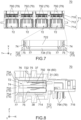
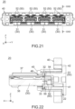
- the retainer 50 seems to be attached to the intermediate structure 18 immediately after the formation of the intermediate structure 18 shown in Figs. 19 and 20 , and thereby the first connector 20 shown in Figs. 21 and 22 is assembled.
- the first connector 20 is actually assembled as described below.
- the end portions 84 of the FPC board 80 are connected to the sub-connectors 30, respectively.
- the sub-connectors 30 and the housing 40 are combined into the intermediate structure 18.
- the retainers 50 are attached to the intermediate structure 18.
- each of the sub-connectors 30 is partially and floatably accommodated in the corresponding accommodation portion 41.
- the first connector 20 is formed with two or more of the slots 22 which correspond to the accommodation portions 41, respectively.
- Each of the slots 22 is a space which is formed between the housing 40 and the cover 51 of the retainer 50 in the front-rear direction.
- each of the slots 22 is located between the housing 40 and the retainer 50 in the front-rear direction.
- each of the slots 22 communicates with the corresponding accommodation portion 41.
- Each of the slots 22 has a size in the front-rear direction which is larger than a thickness of the flat FPC board 80.
- the end portions 84 of the FPC board 80 are configured to be connected to the sub-connectors 30 through the slots 22, respectively.
- the conductive lines (not shown) of the end portions 84 are fixed and connected to the surface mount portions 62 of the first terminals 60, respectively, via soldering, etc.
- the slots 22 are provided, the four end portions 84 of the single FPC board 80 can be connected to the four sub-connectors 30, respectively.
- the first connector 20 of the present embodiment is a connector which comprises two or more of the floatably held sub-connectors 30.
- the sub-connectors 30 of the present embodiment are configured to be connected to two or more of the branching end portions 84 of the FPC board 80, respectively.
- the present embodiment when the sub-connectors 30 connected to the FPC board 80 is attached to the housing 40, the order of the sub-connectors 30 in the left-right direction has been already determined. Therefore, when the sub-connectors 30 is attached to the housing 40, each of the sub-connectors 30 can be attached to a correct position with no mistake.
- the present embodiment provides the connector assembly 12 which comprises the first connector 20 including two or more of the floatably held sub-connectors 30 and which enables the sub-connectors 30 to be attached to correct positions of the housing 40.
- manufacturing cost can be reduced in comparison with an instance where the sub-connectors 30 are provided with mating keys different from each other.
- the first connector 20 is a surface mount connector.
- the connector may be divided into the four sub-connectors 30 so that the number of the first terminals 60 of each of the thus-provided sub-connectors 30 is not more than a predetermined number.
- the surface mount portions 62 of all the first terminals 60 of each of the sub-connectors 30 can be arranged in a common plane in parallel to the XY-plane. The thus-arranged surface mount portions 62 can be properly soldered by a reflow process, for example.
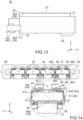
- the second connector 70 of the present embodiment comprises a second housing 71 made of insulator, a plurality of second terminals 79 each made of conductor, a locator 796 made of insulator and two fixing members 798 each made of metal.
- the number of the second terminals 79 is eighty.
- the second terminals 79 are provided so that they correspond to the first terminals 60 (see Fig. 9 ) of the first connector 20, respectively.
- the second terminals 79 are held by the second housing 71.
- the fixing members 798 are press-fit in opposite sides of the second housing 71 in the left-right direction, respectively.
- the fixing members 798 fix the second connector 70 on the second device (not shown) when the second connector 70 is used.
- the second connector 70 of the present embodiment comprises the aforementioned members.
- the present invention is not limited thereto.
- the locator 796 and the fixing members 798 may be provided as necessary.
- the second connector 70 may further comprise another member in addition to the aforementioned members.
- the second housing 71 of the present embodiment extends longer in the left-right direction than in the upper-lower direction.
- the second housing 71 has a partition 712, a connection portion 714 and a mountable portion 716.
- the partition 712, the connection portion 714 and the mountable portion 716 are integrally molded of resin.
- the partition 712 extends in parallel to the YZ-plane as a whole.
- the connection portion 714 is configured to be connected to the first connector 20.
- the connection portion 714 protrudes rearward from the partition 712 and extends in the left-right direction.
- the mountable portion 716 is configured to be mounted on the second device (not shown).
- the mountable portion 716 protrudes forward from the partition 712 and extends in the left-right direction.
- the second connector 70 of the present embodiment has two or more mating portions 72 which correspond to the sub-connectors 30, respectively.
- Each of the mating portions 72 is a space which is enclosed by a mating wall 722 of the second housing 71 in the YZ-plane.
- Each of the mating portions 72 opens rearward and extends to the partition 712 of the second housing 71 in the front-rear direction.
- the mating portions 72 are arranged in the left-right direction.
- each of the sub-connectors 30 is mateable with the corresponding mating portion 72.
- Each of the mating portions 72 holds the second terminals 79 which correspond to the first terminals 60 of the sub-connector 30, respectively.
- Each of the second terminals 79 has a second connection portion 792 and a fixed portion 794.
- the fixed portions 794 are fixed and connected to the second device (not shown).
- the second connection portions 792 are brought into contact with the first connection portions 64 of the first terminals 60, respectively, under the mated state, and thereby the second connector 70 is electrically connected with all the sub-connectors 30.
- all the first terminals 60 divided in the four sub-connectors 30 can be simultaneously connected to all the second terminals 79.
- the second connector 70 of the present embodiment has the aforementioned structure.
- the second connector 70 of the present embodiment has four of the mating portions 72.
- the structure of the second connector 70 is not specifically limited, provided that the second connector 70 has two or more of the mating portions 72 which correspond to the sub-connectors 30, respectively.
- the number of the mating portions 72 may be two, three, five or more.
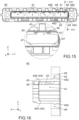
- the mating portion 72 of the present embodiment is provided with a tapered surface 73, two side ribs 74 and four vertical ribs 75.
- the tapered surface 73 is formed of two side tapered surfaces 732 and two vertical tapered surfaces 734.
- the side ribs 74 and the vertical ribs 75 are located forward of the tapered surface 73.
- Each of the side ribs 74 and the vertical ribs 75 has a rear end formed with a sloping surface which is inclined into the mating portion 72.
- the side ribs 74 are located at opposite sides of the mating portion 72 in the left-right direction, respectively, and are located at the middle of the mating portion 72 in the upper-lower direction.
- the side ribs 74 protrude inward in the left-right direction and extend along the front-rear direction.
- the sub-connector 30 is brought into abutment with the inclined rear ends of the side ribs 74 and the vertical ribs 75 after guided into the mating portion 72, and thereby a position of the sub-connector 30 in the YZ-plane is further adjusted.
- the sub-connector 30 is moved forward in the mating portion 72 while being sandwiched between the side ribs 74 in the left-right direction and sandwiched between the vertical ribs 75 in the upper-lower direction.
- the floatable sub-connector 30 can be accurately positioned to the mating portion 72 by the tapered surface 73, the side ribs 74 and the vertical ribs 75.
- the present invention is not limited thereto.
- the tapered surface 73, the side ribs 74 and the vertical ribs 75 may be provided as necessary.
- the two side ribs 74 of the present embodiment are located at positions same as each other in the upper-lower direction.
- the upper two of the four vertical ribs 75 of the present embodiment are located at positions same as those of the lower two in the left-right direction, respectively.
- the sub-connector 30 can be more accurately positioned to the mating portion 72.
- the mating portion 72 may be provided with only two of the vertical ribs 75.
- the vertical ribs 75 may be located at opposite sides of the mating portion 72 in the upper-lower direction, respectively, may protrude inward in the upper-lower direction and may extend along the front-rear direction.
- the size TW and the size TH of the tapered surface 73 of the present embodiment are rather larger than those of the existing technique. According to the present embodiment, even in a case where a position of the first connector 20 in the YZ-plane is relatively largely misaligned to another position of the second connector 70 in the YZ-plane in the mating process in which the first connector 20 is mated with the second connector 70, the tapered surface 73 can adjust the position of the sub-connector 30 in the YZ-plane when a slight forward force is applied to the sub-connector 30.
- the sub-connector 30 is mated with the second connector 70 with a small insertion force.
- the present invention is not limited thereto.
- the size of the tapered surface 73 may be determined as necessary.
- the mating portion 72 is formed with two upper channels 76 located over the mating portion 72 and is formed with two lower channels 77 located under the mating portion 72.
- Each of the upper channels 76 and the lower channels 77 extends through the connection portion 714 along the front-rear direction and opens rearward.
- the upper channels 76 and the lower channels 77 are located at positions different from each other in the left-right direction.
- the second connector 70 is formed with the upper channels 76 which correspond to the upper keys 37 of the sub-connector 30 and the lower channels 77 which correspond to the lower keys 38 of the sub-connector 30.
- the upper keys 37 are received in the upper channels 76, and the lower keys 38 are received in the lower channels 77.
- the upper keys 37 and the lower keys 38 are brought into abutment with the tapered surface 73 of the mating portion 72. and thereby the first connector 20 cannot be mated with the second connector 70.
- the upper keys 37 and the lower keys 38 not only work as keys which prevent the reverse accommodation of the sub-connector 30 in the housing 40 but also work as mating keys which prevent reverse mating of the first connector 20.
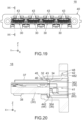
- the first connector 20 and the second connector 70 of the present embodiment are mateable with each other as described above.
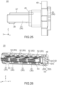
- Fig. 1 together with Figs. 23 and 24 when the first connector 20 is relatively moved toward the second connector 70, each of the sub-connectors 30 receives a rearward force from the second connector 70, and the sub-connectors 30 are simultaneously mated with the second connector 70 while being moved to the rear limit positions. Meanwhile, the rear definers 36 of the sub-connector 30 are brought into abutment with the rear facing portions 58 of the retainer 50 in a plane in parallel to the YZ-plane.
- the abutment areas between the rear definers 36 and the rear facing portions 58 are small. Accordingly, even when the position of the sub-connector 30 in the YZ-plane is misaligned, the sub-connector 30 is smoothly moved to a proper position in the YZ-plane substantially with no friction force and extends straight along the front-rear direction. Thus, the rear definers 36 and the rear facing portions 58 make the posture of the sub-connector 30 stable when the sub-connector 30 is mated.
- each of the sub-connectors 30 receives a forward force from the second connector 70, and the sub-connectors 30 are simultaneously removed from the second connector 70 while being moved to the front limit positions. Meanwhile, the front facing portions 44 of the housing 40 are brought into abutment with the front definers 35 of the sub-connector 30 in a plane in parallel to the YZ-plane. As previously described, the abutment areas between the front facing portions 44 and the front definers 35 are small.
- the sub-connector 30 is smoothly moved in the YZ-plane substantially with no friction force and extends straight along the front-rear direction.
- the front definers 35 and the front facing portions 44 make the posture of the sub-connector 30 stable when the sub-connector 30 is removed.
- the connector assembly 12 of the present embodiment forms the structure 10 together with the FPC board 80 as previously described.
- the structure 10 of the present embodiment comprises the connector assembly 12 and the single FPC board 80 which has two or more of the branching end portions 84.
- the sub-connectors 30 are connected to the end portions 84, respectively.
- each of the mating portions 72 of the second connector 70 of the present embodiment is formed with two key grooves 78 located over the mating portion 72.
- the two upper channels 76 are located between the two key grooves 78 in the left-right direction.
- Each of the key grooves 78 extends along the front-rear direction and opens rearward. The arrangements of the key grooves 78 of the four mating portions 72 are different from each other.
- the second connector 70 may be connected to four connectors (not shown) which are independent of each other and are attached to discrete cables, respectively, instead of the first connector 20 (see Fig. 1 ) of the present embodiment.
- each of the connectors may be provided with mating keys which correspond to the key grooves 78.
- each of the retainers 50 may be provided with a hole through which the end portion 84 of the FPC board 80 can pass along the front-rear direction. Moreover, in an instance where the first connector 20 is provided with none of the retainers 50, the FPC board 80 including the end portions 84 may extend along the front-rear direction. However, according to an instance where none of the retainers 50 is provided, when the first connector 20 is mated with the second connector 70, the sub-connector 30 might come off the accommodation portion 41 (see Fig. 9 ) by a rearward force applied thereto. Therefore, it is preferable that the retainers 50 are provided unless there is a specific reason.
Landscapes
- Details Of Connecting Devices For Male And Female Coupling (AREA)
- Connector Housings Or Holding Contact Members (AREA)
- Coupling Device And Connection With Printed Circuit (AREA)
Applications Claiming Priority (1)
| Application Number | Priority Date | Filing Date | Title |
|---|---|---|---|
| JP2023005978A JP2024101824A (ja) | 2023-01-18 | 2023-01-18 | コネクタ組立体及び構造体 |
Publications (3)
| Publication Number | Publication Date |
|---|---|
| EP4404390A1 EP4404390A1 (en) | 2024-07-24 |
| EP4404390B1 true EP4404390B1 (en) | 2025-07-02 |
| EP4404390C0 EP4404390C0 (en) | 2025-07-02 |
Family
ID=89122160
Family Applications (1)
| Application Number | Title | Priority Date | Filing Date |
|---|---|---|---|
| EP23215094.6A Active EP4404390B1 (en) | 2023-01-18 | 2023-12-07 | Connector assembly and structure comprising the same |
Country Status (5)
| Country | Link |
|---|---|
| US (1) | US20240243521A1 (enExample) |
| EP (1) | EP4404390B1 (enExample) |
| JP (1) | JP2024101824A (enExample) |
| CN (1) | CN118367375A (enExample) |
| HU (1) | HUE072212T2 (enExample) |
Family Cites Families (16)
| Publication number | Priority date | Publication date | Assignee | Title |
|---|---|---|---|---|
| TW419141U (en) * | 1998-12-28 | 2001-01-11 | Hon Hai Prec Ind Co Ltd | Assembly and connection apparatus of electrical connector |
| US6336830B1 (en) * | 2000-08-10 | 2002-01-08 | Compal Electronics, Inc. | Modular connector assembly for an electronic appliance |
| JP2002083578A (ja) | 2000-09-06 | 2002-03-22 | Toyo Kohan Co Ltd | 密閉容器の安全弁装置及びそれを用いた密閉型電池 |
| JP4047535B2 (ja) * | 2000-12-15 | 2008-02-13 | 株式会社オートネットワーク技術研究所 | フラット配線材用コネクタおよびフラット配線材の電気的接続構造 |
| CN101232131B (zh) * | 2007-01-22 | 2010-06-23 | 富士康(昆山)电脑接插件有限公司 | 电连接器组件 |
| US9300081B2 (en) * | 2010-02-02 | 2016-03-29 | Charles Albert Rudisill | Interposer connectors with magnetic components |
| TWI452570B (zh) * | 2010-03-29 | 2014-09-11 | Hon Hai Prec Ind Co Ltd | 硬碟背板結構及採用該硬碟背板結構之硬碟散熱組件 |
| US9478896B2 (en) * | 2011-12-22 | 2016-10-25 | Rolls-Royce Plc | Electrical connectors |
| US9246274B2 (en) * | 2013-03-15 | 2016-01-26 | Panduit Corp. | Communication connectors having crosstalk compensation networks |
| TWM488118U (zh) * | 2014-03-19 | 2014-10-11 | Bing Xu Prec Co Ltd | 線纜連接器 |
| KR102289986B1 (ko) * | 2014-07-22 | 2021-08-17 | 삼성디스플레이 주식회사 | 연성 인쇄회로 케이블 및 케이블 커넥터 어셈블리 |
| US9966703B2 (en) * | 2014-10-17 | 2018-05-08 | Panduit Corp. | Communication connector |
| JP7195974B2 (ja) * | 2019-02-26 | 2022-12-26 | 京セラ株式会社 | コネクタ |
| JP7265443B2 (ja) * | 2019-07-31 | 2023-04-26 | 日本航空電子工業株式会社 | 配線板組立体 |
| US11398694B2 (en) * | 2020-09-29 | 2022-07-26 | TE Connectivity Services Gmbh | Flex jumper assembly for a plug connector assembly |
| DE102024202735A1 (de) * | 2024-03-22 | 2025-09-25 | Yamaichi Electronics Deutschland Gmbh | Kontakt für einen Flachsteckverbinder und Flachsteckverbinder für ein Flachsteckverbindersystem |
-
2023
- 2023-01-18 JP JP2023005978A patent/JP2024101824A/ja active Pending
- 2023-12-07 EP EP23215094.6A patent/EP4404390B1/en active Active
- 2023-12-07 HU HUE23215094A patent/HUE072212T2/hu unknown
- 2023-12-11 US US18/535,839 patent/US20240243521A1/en active Pending
- 2023-12-14 CN CN202311725919.2A patent/CN118367375A/zh active Pending
Also Published As
| Publication number | Publication date |
|---|---|
| CN118367375A (zh) | 2024-07-19 |
| EP4404390A1 (en) | 2024-07-24 |
| HUE072212T2 (hu) | 2025-10-28 |
| JP2024101824A (ja) | 2024-07-30 |
| US20240243521A1 (en) | 2024-07-18 |
| EP4404390C0 (en) | 2025-07-02 |
Similar Documents
| Publication | Publication Date | Title |
|---|---|---|
| US6663426B2 (en) | Floating interface for electrical connector | |
| US5545051A (en) | Board to board matable assembly | |
| US5184961A (en) | Modular connector frame | |
| EP0945921B1 (en) | High speed backplane connector | |
| US12051867B2 (en) | Card edge connector with a locking system | |
| EP0519264B1 (en) | Electrical connector | |
| US5306160A (en) | Self-aligning high-density printed circuit connector | |
| US7785152B2 (en) | High density connector having two-leveled contact interface | |
| US4921435A (en) | Blind mating connector having self-locating feature | |
| US11641073B2 (en) | Connector | |
| US10454194B1 (en) | Card edge connector assembly | |
| CN113745872A (zh) | 浮动连接器 | |
| KR20060096290A (ko) | 전기 커넥터 및 전기 커넥터 조립체 | |
| CN111162394A (zh) | 卡缘电缆连接器组件 | |
| US11398694B2 (en) | Flex jumper assembly for a plug connector assembly | |
| GB2260658A (en) | Electrical connector with module holder | |
| US7938651B2 (en) | Substrate connector | |
| US20180301833A1 (en) | Card-edge connector assembly having card guide modules | |
| US4755143A (en) | Hingeable connector | |
| CN100449872C (zh) | 具有多个卡边沿部分的电连接器模块 | |
| EP4404390B1 (en) | Connector assembly and structure comprising the same | |
| US8647137B2 (en) | Connector | |
| KR20080076901A (ko) | 전기 커넥터 | |
| TW202406239A (zh) | 浮動電連接器 | |
| US6698091B1 (en) | Method and apparatus for coupling circuit boards |
Legal Events
| Date | Code | Title | Description |
|---|---|---|---|
| PUAI | Public reference made under article 153(3) epc to a published international application that has entered the european phase |
Free format text: ORIGINAL CODE: 0009012 |
|
| STAA | Information on the status of an ep patent application or granted ep patent |
Free format text: STATUS: THE APPLICATION HAS BEEN PUBLISHED |
|
| AK | Designated contracting states |
Kind code of ref document: A1 Designated state(s): AL AT BE BG CH CY CZ DE DK EE ES FI FR GB GR HR HU IE IS IT LI LT LU LV MC ME MK MT NL NO PL PT RO RS SE SI SK SM TR |
|
| RAP3 | Party data changed (applicant data changed or rights of an application transferred) |
Owner name: JAPAN AVIATION ELECTRONICS INDUSTRY, LIMITED |
|
| STAA | Information on the status of an ep patent application or granted ep patent |
Free format text: STATUS: REQUEST FOR EXAMINATION WAS MADE |
|
| 17P | Request for examination filed |
Effective date: 20241104 |
|
| RBV | Designated contracting states (corrected) |
Designated state(s): AL AT BE BG CH CY CZ DE DK EE ES FI FR GB GR HR HU IE IS IT LI LT LU LV MC ME MK MT NL NO PL PT RO RS SE SI SK SM TR |
|
| GRAP | Despatch of communication of intention to grant a patent |
Free format text: ORIGINAL CODE: EPIDOSNIGR1 |
|
| STAA | Information on the status of an ep patent application or granted ep patent |
Free format text: STATUS: GRANT OF PATENT IS INTENDED |
|
| RIC1 | Information provided on ipc code assigned before grant |
Ipc: H01R 12/79 20110101ALN20250121BHEP Ipc: H01R 12/77 20110101ALN20250121BHEP Ipc: H01R 13/518 20060101ALI20250121BHEP Ipc: H01R 12/91 20110101AFI20250121BHEP |
|
| INTG | Intention to grant announced |
Effective date: 20250130 |
|
| GRAS | Grant fee paid |
Free format text: ORIGINAL CODE: EPIDOSNIGR3 |
|
| GRAA | (expected) grant |
Free format text: ORIGINAL CODE: 0009210 |
|
| STAA | Information on the status of an ep patent application or granted ep patent |
Free format text: STATUS: THE PATENT HAS BEEN GRANTED |
|
| AK | Designated contracting states |
Kind code of ref document: B1 Designated state(s): AL AT BE BG CH CY CZ DE DK EE ES FI FR GB GR HR HU IE IS IT LI LT LU LV MC ME MK MT NL NO PL PT RO RS SE SI SK SM TR |
|
| REG | Reference to a national code |
Ref country code: GB Ref legal event code: FG4D |
|
| REG | Reference to a national code |
Ref country code: CH Ref legal event code: EP |
|
| REG | Reference to a national code |
Ref country code: DE Ref legal event code: R096 Ref document number: 602023004529 Country of ref document: DE |
|
| REG | Reference to a national code |
Ref country code: IE Ref legal event code: FG4D |
|
| U01 | Request for unitary effect filed |
Effective date: 20250702 |
|
| U07 | Unitary effect registered |
Designated state(s): AT BE BG DE DK EE FI FR IT LT LU LV MT NL PT RO SE SI Effective date: 20250709 |
|
| REG | Reference to a national code |
Ref country code: SK Ref legal event code: T3 Ref document number: E 46772 Country of ref document: SK |
|
| REG | Reference to a national code |
Ref country code: HU Ref legal event code: AG4A Ref document number: E072212 Country of ref document: HU |