EP4404345A2 - Elektrowerkzeug und batteriepack für elektrowerkzeug - Google Patents
Elektrowerkzeug und batteriepack für elektrowerkzeug Download PDFInfo
- Publication number
- EP4404345A2 EP4404345A2 EP24152489.1A EP24152489A EP4404345A2 EP 4404345 A2 EP4404345 A2 EP 4404345A2 EP 24152489 A EP24152489 A EP 24152489A EP 4404345 A2 EP4404345 A2 EP 4404345A2
- Authority
- EP
- European Patent Office
- Prior art keywords
- battery pack
- metal sheet
- electrical terminal
- terminal
- power tool
- Prior art date
- Legal status (The legal status is an assumption and is not a legal conclusion. Google has not performed a legal analysis and makes no representation as to the accuracy of the status listed.)
- Pending
Links
Images


Classifications
-
- H—ELECTRICITY
- H01—ELECTRIC ELEMENTS
- H01M—PROCESSES OR MEANS, e.g. BATTERIES, FOR THE DIRECT CONVERSION OF CHEMICAL ENERGY INTO ELECTRICAL ENERGY
- H01M50/00—Constructional details or processes of manufacture of the non-active parts of electrochemical cells other than fuel cells, e.g. hybrid cells
- H01M50/20—Mountings; Secondary casings or frames; Racks, modules or packs; Suspension devices; Shock absorbers; Transport or carrying devices; Holders
- H01M50/296—Mountings; Secondary casings or frames; Racks, modules or packs; Suspension devices; Shock absorbers; Transport or carrying devices; Holders characterised by terminals of battery packs
-
- B—PERFORMING OPERATIONS; TRANSPORTING
- B25—HAND TOOLS; PORTABLE POWER-DRIVEN TOOLS; MANIPULATORS
- B25F—COMBINATION OR MULTI-PURPOSE TOOLS NOT OTHERWISE PROVIDED FOR; DETAILS OR COMPONENTS OF PORTABLE POWER-DRIVEN TOOLS NOT PARTICULARLY RELATED TO THE OPERATIONS PERFORMED AND NOT OTHERWISE PROVIDED FOR
- B25F5/00—Details or components of portable power-driven tools not particularly related to the operations performed and not otherwise provided for
-
- H—ELECTRICITY
- H01—ELECTRIC ELEMENTS
- H01M—PROCESSES OR MEANS, e.g. BATTERIES, FOR THE DIRECT CONVERSION OF CHEMICAL ENERGY INTO ELECTRICAL ENERGY
- H01M10/00—Secondary cells; Manufacture thereof
- H01M10/60—Heating or cooling; Temperature control
- H01M10/62—Heating or cooling; Temperature control specially adapted for specific applications
- H01M10/623—Portable devices, e.g. mobile telephones, cameras or pacemakers
- H01M10/6235—Power tools
-
- H—ELECTRICITY
- H01—ELECTRIC ELEMENTS
- H01M—PROCESSES OR MEANS, e.g. BATTERIES, FOR THE DIRECT CONVERSION OF CHEMICAL ENERGY INTO ELECTRICAL ENERGY
- H01M10/00—Secondary cells; Manufacture thereof
- H01M10/60—Heating or cooling; Temperature control
- H01M10/65—Means for temperature control structurally associated with the cells
- H01M10/653—Means for temperature control structurally associated with the cells characterised by electrically insulating or thermally conductive materials
-
- H—ELECTRICITY
- H01—ELECTRIC ELEMENTS
- H01M—PROCESSES OR MEANS, e.g. BATTERIES, FOR THE DIRECT CONVERSION OF CHEMICAL ENERGY INTO ELECTRICAL ENERGY
- H01M50/00—Constructional details or processes of manufacture of the non-active parts of electrochemical cells other than fuel cells, e.g. hybrid cells
- H01M50/20—Mountings; Secondary casings or frames; Racks, modules or packs; Suspension devices; Shock absorbers; Transport or carrying devices; Holders
- H01M50/204—Racks, modules or packs for multiple batteries or multiple cells
-
- H—ELECTRICITY
- H01—ELECTRIC ELEMENTS
- H01M—PROCESSES OR MEANS, e.g. BATTERIES, FOR THE DIRECT CONVERSION OF CHEMICAL ENERGY INTO ELECTRICAL ENERGY
- H01M50/00—Constructional details or processes of manufacture of the non-active parts of electrochemical cells other than fuel cells, e.g. hybrid cells
- H01M50/20—Mountings; Secondary casings or frames; Racks, modules or packs; Suspension devices; Shock absorbers; Transport or carrying devices; Holders
- H01M50/244—Secondary casings; Racks; Suspension devices; Carrying devices; Holders characterised by their mounting method
-
- H—ELECTRICITY
- H01—ELECTRIC ELEMENTS
- H01M—PROCESSES OR MEANS, e.g. BATTERIES, FOR THE DIRECT CONVERSION OF CHEMICAL ENERGY INTO ELECTRICAL ENERGY
- H01M50/00—Constructional details or processes of manufacture of the non-active parts of electrochemical cells other than fuel cells, e.g. hybrid cells
- H01M50/20—Mountings; Secondary casings or frames; Racks, modules or packs; Suspension devices; Shock absorbers; Transport or carrying devices; Holders
- H01M50/247—Mountings; Secondary casings or frames; Racks, modules or packs; Suspension devices; Shock absorbers; Transport or carrying devices; Holders specially adapted for portable devices, e.g. mobile phones, computers, hand tools or pacemakers
-
- H—ELECTRICITY
- H01—ELECTRIC ELEMENTS
- H01M—PROCESSES OR MEANS, e.g. BATTERIES, FOR THE DIRECT CONVERSION OF CHEMICAL ENERGY INTO ELECTRICAL ENERGY
- H01M50/00—Constructional details or processes of manufacture of the non-active parts of electrochemical cells other than fuel cells, e.g. hybrid cells
- H01M50/20—Mountings; Secondary casings or frames; Racks, modules or packs; Suspension devices; Shock absorbers; Transport or carrying devices; Holders
- H01M50/284—Mountings; Secondary casings or frames; Racks, modules or packs; Suspension devices; Shock absorbers; Transport or carrying devices; Holders with incorporated circuit boards, e.g. printed circuit boards [PCB]
-
- H—ELECTRICITY
- H01—ELECTRIC ELEMENTS
- H01M—PROCESSES OR MEANS, e.g. BATTERIES, FOR THE DIRECT CONVERSION OF CHEMICAL ENERGY INTO ELECTRICAL ENERGY
- H01M50/00—Constructional details or processes of manufacture of the non-active parts of electrochemical cells other than fuel cells, e.g. hybrid cells
- H01M50/50—Current conducting connections for cells or batteries
- H01M50/543—Terminals
- H01M50/547—Terminals characterised by the disposition of the terminals on the cells
- H01M50/55—Terminals characterised by the disposition of the terminals on the cells on the same side of the cell
-
- H—ELECTRICITY
- H01—ELECTRIC ELEMENTS
- H01M—PROCESSES OR MEANS, e.g. BATTERIES, FOR THE DIRECT CONVERSION OF CHEMICAL ENERGY INTO ELECTRICAL ENERGY
- H01M2220/00—Batteries for particular applications
- H01M2220/30—Batteries in portable systems, e.g. mobile phone, laptop
-
- Y—GENERAL TAGGING OF NEW TECHNOLOGICAL DEVELOPMENTS; GENERAL TAGGING OF CROSS-SECTIONAL TECHNOLOGIES SPANNING OVER SEVERAL SECTIONS OF THE IPC; TECHNICAL SUBJECTS COVERED BY FORMER USPC CROSS-REFERENCE ART COLLECTIONS [XRACs] AND DIGESTS
- Y02—TECHNOLOGIES OR APPLICATIONS FOR MITIGATION OR ADAPTATION AGAINST CLIMATE CHANGE
- Y02E—REDUCTION OF GREENHOUSE GAS [GHG] EMISSIONS, RELATED TO ENERGY GENERATION, TRANSMISSION OR DISTRIBUTION
- Y02E60/00—Enabling technologies; Technologies with a potential or indirect contribution to GHG emissions mitigation
- Y02E60/10—Energy storage using batteries
Definitions
- the present invention relates to the field of power tools, and in particular to a power tool and a battery pack with a metal sheet electrical terminal for power tools.
- the power tool connection end of a battery pack is electrically connected to a control circuit, for example, a printed circuit board (PCB), of the battery pack through wires.
- a control circuit for example, a printed circuit board (PCB)
- the wires which have a high resistance, generate a large amount of heat in the battery pack; moreover, the battery pack may overheat after prolonged use of the power tool, and the wires may need to transmit a high current during the operation of the power tool to ensure proper operation of the power tool, wherein such a high current may also lead to safety issues with the battery pack due to the use of wires.
- a design including wires requires more space, and the weld between a wire and a PCB or another component may come off or become faulty due to continuous vibration of the battery pack during operation, which also leads to safety issues and may render the power tool unable to operate properly.
- An objective of the present invention is to solve at least some of the above-mentioned problems, wherein the present invention proposes a battery pack with improved thermal management and improved safety, as well as a cordless power tool comprising such a battery pack.
- a battery pack comprising:
- the metal sheet electrical terminal has a substantially inverted U-shaped structure, the U-shaped structure extending along the power tool connection end.
- the two legs of the U-shaped structure each comprise a terminal lower end, each terminal lower end being directly electrically connected to the PCB.
- the metal sheet electrical terminal comprises a positive metal sheet electrical terminal and a negative metal sheet electrical terminal, the positive metal sheet electrical terminal and the negative metal sheet electrical terminal being separated by a spacer.
- a bottom portion of the U-shaped structure is wider than a top portion of the U-shaped structure.
- the bottom portion of the U-shaped structure is formed with an electrical contact portion for connecting to the electrical terminals of the power tool.
- the positive metal sheet electrical terminal and the negative metal sheet electrical terminal are moulded together with the spacer.
- the metal sheet electrical terminal is in the form of an integral metal sheet with three or more legs, each leg comprising a terminal lower end, and each terminal lower end being directly electrically connected to the PCB.
- the metal sheet electrical terminal comprises a positive metal sheet electrical terminal and a negative metal sheet electrical terminal, each of the positive metal sheet electrical terminal and the negative metal sheet electrical terminal having a terminal lower end, and each terminal lower end being directly electrically connected to the PCB.
- the battery pack housing comprises a battery pack upper housing and a battery pack lower housing
- the battery pack upper housing has a battery pack joint surface located at the top, a boss extending vertically to a certain height perpendicular to the battery pack joint surface, and a protruding column extending vertically to a certain height perpendicular to the boss, the power tool connection end being inserted into the protruding column of the battery pack upper housing.
- the battery pack further comprises a heat-insulating plate substantially covering the metal sheet electrical terminal.
- the battery pack further comprises a collector plate electrically connected to the PCB on the side of the PCB opposite to the power tool connection end.
- the collector plate comprises a positive collector plate configured to be electrically connected to the positive electrode of the battery unit; and a negative collector plate configured to be electrically connected to the negative electrode of the battery unit.
- the metal sheet electrical terminal comprises a positive metal sheet electrical terminal and a negative metal sheet electrical terminal, the terminal lower end of the positive metal sheet electrical terminal being directly electrically connected to the positive collector plate, and/or the terminal lower end of the negative metal sheet electrical terminal being directly electrically connected to the negative collector plate.
- a plurality of electrical terminals are provided at the top of the protruding column, and the metal sheet electrical terminal is electrically connected to the electrical terminal of the protruding column, the electrical terminal of the protruding column being configured to be electrically connected to an electrical connector in the base of the power tool.
- a power tool comprising a battery pack according to an embodiment of the present application.
- the metal sheet electrical terminal is an integrated electrical terminal directly connected to a PCB to electrically connect from the PCB to the electrical terminal, replacing any additional wires used in a conventional design.
- the metal sheet electrical terminal has a substantially inverted U-shaped structure, which means that the metal sheet electrical terminal adopts a two-path design, wherein each leg is electrically connected to the PCB and the corresponding collector plate, which means that the metal sheet electrical terminal has two current paths in parallel to reduce or lower the current flowing through each leg or terminal lower end to reduce its current intensity, thus reducing the heating thereof.
- a high current is transmitted to an electrode terminal through a collector plate, which can minimise the direct flow of large currents on the PCB, thus reducing the heating of the PCB.
- a metal sheet electrical terminal with more than one leg has the additional advantage of the formation of a redundant structure, wherein even if the terminal lower end of one leg is electrically disconnected from the PCB or the corresponding collector plate, the other leg remains electrically connected to the PCB and the corresponding collector plate, and so the battery pack can still supply power to the power tool through this other leg, thus ensuring the proper operation of the power tool.
- connection should be understood in a broad sense, wherein, for example, these terms can refer to fixed connection, detachable connection, or integrated connection; mechanical connection or electrical connection; direct connection or connection through an intermediate medium.
- connection should be understood in a broad sense, wherein, for example, these terms can refer to fixed connection, detachable connection, or integrated connection; mechanical connection or electrical connection; direct connection or connection through an intermediate medium.
- orientations or positional relationships indicated by terms such as “central”, “longitudinal”, “lateral”, “upper”, “lower”, “front”, “rear”, “left”, “right”, “vertical”, “horizontal”, “top”, “bottom”, “inner”, “outer”, “axial”, “radial”, and “circumferential” are usually based on the orientations or positional relationships shown in the drawings, are only intended for convenience of describing the present invention and brevity of description, rather than indicating or implying that the device or element referred to necessarily has a specific orientation or is constructed and operated in a specific orientation, and therefore should not be understood as a limitation of the protection scope of the present invention.
- the present invention relates to a power tool 100. While the concept of the present invention is described herein using examples such as reciprocating saws, the present invention is not limited thereto, and power tools may also be other types of power tools known or common in the art, such as drilling rigs, drill hammers, impact drills, other types of saws such as piercing saws, planers, pullers, milling cutters, grinding tools, angle grinders, vibration grinders, gardening tools, and/or multifunctional tools, wherein, indeed, the inventive concept disclosed herein is also applicable to these power tools.
- power tools may also be other types of power tools known or common in the art, such as drilling rigs, drill hammers, impact drills, other types of saws such as piercing saws, planers, pullers, milling cutters, grinding tools, angle grinders, vibration grinders, gardening tools, and/or multifunctional tools, wherein, indeed, the inventive concept disclosed herein is also applicable to these power tools.
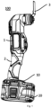
- Fig. 1 is a schematic perspective view of a power tool 100 according to an embodiment of the present invention.
- the power tool 100 comprises a housing 1 and a battery pack 20 detachably mounted at one end of the housing 1, and the other end of the housing 1 is a machining tool, which, in some embodiments, is a saw blade 3, as shown in Fig. 1 , for example.
- the housing 1 has an elongated shape, with its overall direction of extension defined as vertical or longitudinal, the end where the machining tool is located is defined as the top or upper end, and the end where the battery pack 20 is located is defined as the bottom or lower end. In other words, the battery pack 20 is mounted at the bottom of the power tool 100.
- front In addition, the terms "front”, “forward direction” or “forepart” as well as “back”, “rear” or “back side” and other related terms indicating the front and rear direction described in the following text are described relative to the machining tool of the power tool, the end of the battery pack or the base described in the following text facing and close to the machining tool is defined as the front end and may be referred to as the forward direction, forepart, etc., and the other end opposite to this end is referred to as the rear, back side, etc.
- the housing 1 of the power tool 100 comprises a power system and an output shaft driven by the power system.
- the power system comprises an electric motor accommodated in the housing 1, the electric motor driving the output shaft to perform corresponding actions.
- the housing 1 comprises a handle 2 located in a lower position, the handle 2 extending longitudinally.
- a base 10 is provided at the bottom of the power tool 10 (that is, the end of the handle 2 away from the housing 1) for installing the battery pack 20.
- the battery pack 20 is detachably mounted on the base 10.
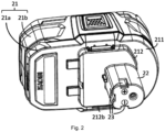
- Fig. 2 is a schematic perspective view of a battery pack for power tools according to an embodiment of the present invention.
- the battery pack 20 comprises an internally hollow battery pack housing 21, which is designable according to the type of power tool and the number of required battery cells or battery units, and may be in various three-dimensional shapes, including, but not limited to, cuboids, cubes, spheres, or other regular or irregular polygons.
- a plurality of rechargeable battery units or batteries are accommodable in a closed space of the battery pack housing 21.
- a lithium battery unit is preferably used as a battery unit.
- the battery pack housing 21 comprises a battery pack upper housing 21a and a battery pack lower housing 21b. Since the battery pack 20 is detachably mountable onto the housing 1, the battery pack housing 21 and the housing 1 are shaped to fit each other to facilitate disassembly and assembly.
- the battery pack upper housing 21a has a battery pack joint surface 211 located at the top, a boss 212 extending vertically to a certain height perpendicular to the battery pack joint surface 211, and a protruding column 22 extending vertically to a certain height perpendicular to the boss 212.
- the battery pack joint surface 211 may be an integral planar shape or a segmented surface with a plurality of steps, and, in some embodiments, there may be no bosses 212 present.
- the boss 212 may be in the shape of a rectangular boss, but is not limited thereto, wherein it may also be a circular boss, a triangular boss, or another regularly or irregularly shaped boss, and the height of the boss is designable according to specific applications.
- a plurality of electrical terminals 23, such as a positive terminal, a negative terminal, a grounding terminal, etc., are arranged at the top of the protruding column 22.
- the battery pack housing 21 and the electrical terminals 23 thereon may be referred to as the connection interface of the battery pack, which is used to connect to the housing 1.
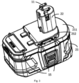
- Fig. 3 is a schematic diagram of an electrical connection between the battery pack 20 and the power tool 100 in an installed state of a power tool according to an embodiment of the present invention, wherein only the electrical connector 11 of the power tool is shown.
- the battery pack 20 When the battery pack 20 is in an installed state, the battery pack 20 is inserted into the base 10 of the power tool 100, wherein the electrical terminals 23 of the battery pack 20 are electrically connected to the electrical connector 11 of the power tool 100, and so that the power of the battery pack 20 may be provided to the power tool 100, thereby allowing operations of the power tool 100, for example, moving a saw blade to and fro for cutting.
- the base 10 of the power tool 100 comprises a groove with a shape complementary to the boss 212, a slot extending from the groove to the interior of the housing 1 with a shape complementary to the protruding column 22, and a base joint surface that abuts against the battery pack joint surface 211, wherein none of these features of the base 10 are shown in Fig. 3 .
- the protruding column 22 When the battery pack housing 21 is mounted on the base 10, the protruding column 22 is inserted into the slot, the boss 212 is assembled into the groove, the base joint surface abuts against the battery pack joint surface 211, and the battery pack housing 21 and base 10 are connected to each other, for example, through mounting features (such as protrusions and threaded holes) on the protruding column 22 and the matching mounting features in the slot, wherein, at the same time, the electrical terminals 23 on the protruding column 22 come into contact with the electrical connector 11 in the slot, conducting a current to provide power to the battery pack 20.
- mounting features such as protrusions and threaded holes
- the battery pack housing 21 when the battery pack housing 21 is removed from the base 10, the protruding column 22 is pulled out of the slot, the electrical terminals 23 are disjoined from the electrical connector 11 in the slot, the boss 212 is separated from the groove, and the base joint surface is disengaged from the battery pack joint surface 211.
- the battery pack housing 21 achieves a plug-pull fit with the base 10.
- damping element 15 in order to attenuate or even eliminate the vibrations transmitted from the housing 1 to the battery pack 20, at least one damping element 15 is arranged therebetween. While three pairs of damping elements 15 are shown in Fig. 3 , the present invention is not limited thereto, and the number of damping elements 15 may be optionally set according to specific applications, such as only 1, 2, 3, 5, 7 or more, or another number. Fig. 3 shows that the damping element 15 has a cylindrical shape, but indeed, the damping element 15 may also have another shape.
- the damping element 15 may be made of an elastic material, for example, rubber or another material having elasticity. In addition, the damping element 15 may also be implemented in the form of flexible rubber instead of a rubber column.
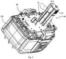
- Fig. 4 is a schematic perspective view of a battery pack 20 according to an embodiment of the present invention, wherein the battery pack upper housing 21a is removed to better show the internal structure of the battery pack.
- Fig. 5 is a sectional view of the battery pack 20 according to an embodiment of the present invention in Fig. 4 taken along line A-A.
- the battery pack 20 comprises a power tool connection end 30, a printed circuit board (PCB) 40, a battery unit 50 (see Fig. 5 ), and other related components.
- the PCB 40 comprises a control circuit.
- the power tool connection end 30 is configured to be electrically connected to the power tool 100, so that the battery pack 20 can supply power to the power tool 100.
- the PCB 40 is electrically connected to the power tool connection end 30 and electrically connected to the battery unit 50 to control the power supply to the power tool 100.
- the power tool connection end 30 is inserted into the protruding column 22 of the battery pack upper housing 21a.
- the power tool connection end 30 is electrically connected to the electrical terminal 23, the electrical terminal 23 in turn is electrically connected to the electrical connector 11 of the power tool 100, and so that electricity may be transmitted from the battery pack 20 to the power tool 100, especially the power system, for example, an electric motor, thereof, thereby allowing operations of the power tool 100.
- the power tool connection end 30 comprises a metal sheet electrical terminal 31, and the metal sheet electrical terminal 31 is configured to be electrically connected to the electrical terminal 23.
- the metal sheet electrical terminal 31 is electrically connected to the electrical terminal 23 of the protruding column.
- the metal sheet electrical terminal 31 is an integral electrical terminal directly connected to the PCB 40, thereby replacing any additional or separately arranged wires used in a conventional design.
- the electrical terminal 23 comprises a positive terminal, a negative terminal, and a grounding terminal.
- the electrical connector 11 may comprise a positive electrode electrical connector 11, a negative electrode electrical connector 11, and a grounding electrical connector (not shown in Fig. 3 ).
- the metal sheet electrical terminal 31 comprises a positive metal sheet electrical terminal 311, a negative metal sheet electrical terminal 312, and a grounding metal sheet electrical terminal 313.
- the grounding metal sheet electrical terminal 313 may also be a communication terminal.
- the positive metal sheet electrical terminal 311 and the negative metal sheet electrical terminal 312 are separated by a spacer 316 (as shown in Fig. 8 ).
- the positive metal sheet electrical terminal 311 and the negative metal sheet electrical terminal 312 are moulded together with the spacer 316. For example, as shown in Fig. 5 and Fig.
- the metal sheet electrical terminal 31 on the left corresponds to the positive metal sheet electrical terminal 31, and the metal sheet electrical terminal 31 on the right corresponds to the negative metal sheet electrical terminal 31.
- the spacer 316 is formed of an insulating material that is heat-resistant and thermally conductive.
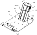
- Fig. 6 is a schematic perspective view of the power tool connection end 30 and the printed circuit board (PCB) 40 of a battery pack 20 according to an embodiment of the present invention, wherein the electrical connection between the power tool connection end 30 and the PCB 40 is shown.
- Fig. 7 is a schematic perspective view, taken from another perspective, of the power tool connection end 30 and PCB 40 of a battery pack 20 according to an embodiment of the present invention.
- the power tool connection end 30 is disposed on the PCB 40.
- the power tool connection end 30 comprises a metal sheet electrical terminal 31, which extends vertically perpendicular to the plane of the PCB 40.
- the metal sheet electrical terminal 31 is directly electrically connected to the PCB 40.
- the metal sheet electrical terminal 31 is an integral electrical terminal directly connected to the PCB 40 to electrically connect from the PCB to the electrical terminal, replacing any additional wires used in a conventional design. Establishing a direct connection to the PCB 40 with an integral electrical terminal 31 allows a reduction in the heat generated during the operation of the battery pack and provides greater safety at higher currents.
- the integral electrical terminal 31 can provide more reliable electrical connections.
- the top of the power tool connection end 30 further comprises a heat-insulating plate 317, and the heat-insulating plate 317 is located between the metal sheet electrical terminal 31 and the outer housing.
- the heat-insulating plate 317 substantially covers the metal sheet electrical terminal 31.
- the heat-insulating plate may be formed of materials such as mica plates.
- the metal sheet electrical terminal 31 comprises a terminal lower end 32, and the terminal lower end 32 is electrically connected to the PCB 40.
- a collector plate is electrically connected to the lower surface of the PCB 40, wherein, for example, the collector plate comprises a positive collector plate 61, the positive collector plate 61 used for electrical connection to the positive electrode of the battery unit 50; and a negative collector plate 62, the negative collector plate 62 used for electrical connection to the negative electrode of the battery unit 50.
- the terminal lower end 32 of the positive metal sheet electrical terminal 31 is electrically connected to the positive collector plate 61, and/or the terminal lower end 32 of the negative metal sheet electrical terminal 31 is electrically connected to the negative collector plate 62.
- High currents are transmitted to the electrode terminals through the collector plates, which minimises the direct flow of high currents on the PCB to reduce the heating of the PCB.
- the metal sheet electrical terminal 31 is designed with a single metal sheet located substantially in the same plane, in which case the metal sheet electrical terminal 31 has a single terminal lower end 32 electrically connected to the PCB 40 and to the corresponding collector plate.
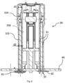
- Fig. 8 is a sectional view of the power tool connection end of a battery pack according to an embodiment of the present invention and the PCB taken along the line B-B in Fig. 6 .
- the metal sheet electrical terminal 31 adopts a substantially inverted U-shaped structure extending along the power tool connection end, as shown in Fig. 8 .
- the metal sheet electrical terminal 31 is formed into a substantially inverted U-shaped structure by bending a single metal sheet that is substantially in the same plane backwards about 180 degrees at the approximate midpoint of its longitudinal direction, and the two legs of the U-shaped structure are substantially parallel to each other.
- each leg comprises a terminal lower end 32.
- each metal sheet electrical terminal 31 has two terminal lower ends 32, each terminal lower end 32 being electrically connected to the PCB 40 and to the corresponding collector plate.
- the metal sheet electrical terminal 31 adopts a two-path design, wherein each leg is electrically connected to the PCB 40 and the corresponding collector plate, which means that the metal sheet electrical terminal 31 has two current paths in parallel to reduce or lower the current flowing through each leg or terminal lower end 32 to reduce its current intensity, thus reducing the heating thereof.
- a metal sheet electrical terminal 31 with more than one leg has the additional advantage of the formation of a redundant structure, wherein even if the terminal lower end 32 of one leg is electrically disconnected from the PCB 40 or the corresponding collector plate, the other leg remains electrically connected to the PCB 40 and the corresponding collector plate, and so the battery pack can still supply power to the power tool 100 through this other leg, thus ensuring the proper operation of the power tool 100.
- the U-shaped structure can also provide a certain degree of elasticity, ensuring a tighter electrical connection with another joint, which effectively reduces the heating of the connecting parts.
- the U-shaped structure comprises a bottom portion 314 located on the upper side and a top portion 315 located on the lower side.
- the lower part of the leg or the terminal lower end 32 forms the top portion of the U-shaped structure.
- the bottom portion 314 of the U-shaped structure is wider than the top portion 315 of the U-shaped structure.
- the bottom portion 314 comprises a width d1
- the top portion 315 comprises a width d2, wherein d2 ⁇ d1.
- the U-shaped structure protrudes outwards relative to the top portion 315 at the bottom portion 314.
- the bottom portion 314 of the U-shaped structure forms an electrical contact portion for connecting to the electrical terminals of the power tool.
- the bottom portion 314 protrudes outwards relative to the top portion 315, making it more convenient to connect the U-shaped structure to the electrical terminals of the power tool.
- the positive metal plate electrical terminal 31 on the left comprises two legs parallel to each other, each leg having a terminal lower end 32.
- Each terminal lower end 32 passes through the PCB 40 and the positive collector plate 61.
- the PCB 40 has a corresponding slit at a position corresponding to the terminal lower end 32, through which the terminal lower end 32 may pass and is electrically connected to the terminal lower end 32 at that position.
- the positive collector plate 61 has a corresponding slit at a position corresponding to the terminal lower end 32, through which the terminal lower end 32 may pass and is electrically connected to the terminal lower end 32 at that position.
- the negative metal plate electrical terminal 31 on the right also comprises two legs parallel to each other, each leg having a terminal lower end 32.
- Each terminal lower end 32 passes through the PCB 40 and the negative collector plate 62.
- the PCB 40 has a corresponding slit at a position corresponding to the terminal lower end 32, through which the terminal lower end 32 may pass and is electrically connected to the terminal lower end 32 at that position.
- the negative collector plate 62 has a corresponding slit at a position corresponding to the terminal lower end 32, through which the terminal lower end 32 may pass and is electrically connected to the terminal lower end 32 at that position.
- the metal sheet electrical terminal 31 may also adopt another shape and structure.
- the metal sheet electrical terminal 31 may be in the form of an integral metal sheet with three or more legs, wherein each leg is correspondingly electrically connected to the PCB 40 and to the corresponding collector plate.
- a plurality of heat sinks may also be arranged in the battery pack so that heat generated inside the battery pack is better dissipated into the environment.
- a plurality of openings may be provided in the battery pack housing 21 of battery pack 20 to improve the heat dissipation effect of the battery pack and help reduce the temperature inside the battery pack.
- cooling fins may also be provided on the exposed channel walls, to increase the heat dissipation area and improve the heat dissipation efficiency.
Landscapes
- Chemical & Material Sciences (AREA)
- Chemical Kinetics & Catalysis (AREA)
- Electrochemistry (AREA)
- General Chemical & Material Sciences (AREA)
- Engineering & Computer Science (AREA)
- Life Sciences & Earth Sciences (AREA)
- Biophysics (AREA)
- Manufacturing & Machinery (AREA)
- Computer Hardware Design (AREA)
- Mechanical Engineering (AREA)
- Battery Mounting, Suspending (AREA)
Applications Claiming Priority (1)
| Application Number | Priority Date | Filing Date | Title |
|---|---|---|---|
| CN202310090008.0A CN118367297A (zh) | 2023-01-19 | 2023-01-19 | 电动工具和用于电动工具的电池包 |
Publications (2)
| Publication Number | Publication Date |
|---|---|
| EP4404345A2 true EP4404345A2 (de) | 2024-07-24 |
| EP4404345A3 EP4404345A3 (de) | 2024-12-11 |
Family
ID=89661437
Family Applications (1)
| Application Number | Title | Priority Date | Filing Date |
|---|---|---|---|
| EP24152489.1A Pending EP4404345A3 (de) | 2023-01-19 | 2024-01-17 | Elektrowerkzeug und batteriepack für elektrowerkzeug |
Country Status (3)
| Country | Link |
|---|---|
| EP (1) | EP4404345A3 (de) |
| CN (1) | CN118367297A (de) |
| AU (1) | AU2024200338A1 (de) |
Families Citing this family (1)
| Publication number | Priority date | Publication date | Assignee | Title |
|---|---|---|---|---|
| WO2026152278A1 (en) * | 2025-01-15 | 2026-07-23 | Nanjing Chervon Industry Co., Ltd. | Battery pack |
Family Cites Families (1)
| Publication number | Priority date | Publication date | Assignee | Title |
|---|---|---|---|---|
| JP6954352B2 (ja) * | 2017-07-21 | 2021-10-27 | 工機ホールディングス株式会社 | 電池パックを用いた電気機器 |
-
2023
- 2023-01-19 CN CN202310090008.0A patent/CN118367297A/zh active Pending
-
2024
- 2024-01-17 EP EP24152489.1A patent/EP4404345A3/de active Pending
- 2024-01-18 AU AU2024200338A patent/AU2024200338A1/en active Pending
Also Published As
| Publication number | Publication date |
|---|---|
| AU2024200338A1 (en) | 2024-08-08 |
| EP4404345A3 (de) | 2024-12-11 |
| CN118367297A (zh) | 2024-07-19 |
Similar Documents
| Publication | Publication Date | Title |
|---|---|---|
| JP7120368B2 (ja) | 電池パック及び電池パックを用いた電気機器 | |
| CN101140984B (zh) | 电池组以及电池组与电动工具或充电器的组件 | |
| EP2328205B1 (de) | Batteriepack | |
| CN107431158B (zh) | 用于手持式工具机的蓄电池组和相应的手持式工具机 | |
| US6237698B1 (en) | Terminal protection system for portable power tools | |
| WO2018079723A1 (ja) | 電池パック及び電池パックを用いた電気機器、電気機器システム | |
| EP4046754B1 (de) | Elektrowerkzeug und elektrische steuerungsanordnung dafür | |
| JP2019021603A (ja) | 電池パック及び電池パックを用いた電気機器、電気機器システム | |
| US20240090374A1 (en) | Power tool | |
| CN211629166U (zh) | 一种电池组件 | |
| EP4213291A2 (de) | Batteriepack und kollektorplattenanordnung für batteriepack | |
| US10461301B2 (en) | Battery pack for a hand-held power tool and method for manufacturing a current-carrying connection, preferably a cell connector of a battery pack for a hand-held power tool | |
| AU2024200338A1 (en) | Power tool and battery pack for power tool | |
| WO2013138955A1 (zh) | 用于电动工具的锂电池包接口座 | |
| JP7285446B2 (ja) | 電動工具用の電池パック、電動工具 | |
| CN116528535B (zh) | 一种电连接件装配结构、配电盒及其制备方法 | |
| CN119069970B (zh) | 一种电池单体、电池及用电装置 | |
| CN211681921U (zh) | 电动工具 | |
| WO2025098063A1 (zh) | 用于给电动工具供电的电池包 | |
| CN217097637U (zh) | 一种手持式直流电动工具 | |
| CN215848026U (zh) | 电池包及电动工具 | |
| CN115051096A (zh) | 电池组 | |
| CN222785419U (zh) | 圆柱电池及电子设备 | |
| CN224264102U (zh) | 用于电钻的电池包组件 | |
| CN222601211U (zh) | 一种电池包 |
Legal Events
| Date | Code | Title | Description |
|---|---|---|---|
| PUAI | Public reference made under article 153(3) epc to a published international application that has entered the european phase |
Free format text: ORIGINAL CODE: 0009012 |
|
| STAA | Information on the status of an ep patent application or granted ep patent |
Free format text: STATUS: THE APPLICATION HAS BEEN PUBLISHED |
|
| AK | Designated contracting states |
Kind code of ref document: A2 Designated state(s): AL AT BE BG CH CY CZ DE DK EE ES FI FR GB GR HR HU IE IS IT LI LT LU LV MC ME MK MT NL NO PL PT RO RS SE SI SK SM TR |
|
| PUAL | Search report despatched |
Free format text: ORIGINAL CODE: 0009013 |
|
| AK | Designated contracting states |
Kind code of ref document: A3 Designated state(s): AL AT BE BG CH CY CZ DE DK EE ES FI FR GB GR HR HU IE IS IT LI LT LU LV MC ME MK MT NL NO PL PT RO RS SE SI SK SM TR |
|
| RIC1 | Information provided on ipc code assigned before grant |
Ipc: H01M 50/296 20210101ALI20241104BHEP Ipc: H01M 50/284 20210101ALI20241104BHEP Ipc: H01M 50/247 20210101ALI20241104BHEP Ipc: H01M 50/204 20210101AFI20241104BHEP |
|
| STAA | Information on the status of an ep patent application or granted ep patent |
Free format text: STATUS: REQUEST FOR EXAMINATION WAS MADE |
|
| 17P | Request for examination filed |
Effective date: 20250611 |